EP4040405A2 - Verfahren und vorrichtung zur verfolgung von sichtlinie, einrichtung, speichermedium und computerprogrammprodukt - Google Patents
Verfahren und vorrichtung zur verfolgung von sichtlinie, einrichtung, speichermedium und computerprogrammprodukt Download PDFInfo
- Publication number
- EP4040405A2 EP4040405A2 EP22179224.5A EP22179224A EP4040405A2 EP 4040405 A2 EP4040405 A2 EP 4040405A2 EP 22179224 A EP22179224 A EP 22179224A EP 4040405 A2 EP4040405 A2 EP 4040405A2
- Authority
- EP
- European Patent Office
- Prior art keywords
- image
- sight line
- coordinate system
- driver
- poi
- Prior art date
- Legal status (The legal status is an assumption and is not a legal conclusion. Google has not performed a legal analysis and makes no representation as to the accuracy of the status listed.)
- Withdrawn
Links
Images


Classifications
-
- G—PHYSICS
- G06—COMPUTING OR CALCULATING; COUNTING
- G06F—ELECTRIC DIGITAL DATA PROCESSING
- G06F3/00—Input arrangements for transferring data to be processed into a form capable of being handled by the computer; Output arrangements for transferring data from processing unit to output unit, e.g. interface arrangements
- G06F3/13—Digital output to plotter ; Cooperation and interconnection of the plotter with other functional units
-
- G—PHYSICS
- G06—COMPUTING OR CALCULATING; COUNTING
- G06V—IMAGE OR VIDEO RECOGNITION OR UNDERSTANDING
- G06V40/00—Recognition of biometric, human-related or animal-related patterns in image or video data
- G06V40/10—Human or animal bodies, e.g. vehicle occupants or pedestrians; Body parts, e.g. hands
- G06V40/18—Eye characteristics, e.g. of the iris
- G06V40/193—Preprocessing; Feature extraction
-
- G—PHYSICS
- G06—COMPUTING OR CALCULATING; COUNTING
- G06T—IMAGE DATA PROCESSING OR GENERATION, IN GENERAL
- G06T7/00—Image analysis
- G06T7/70—Determining position or orientation of objects or cameras
-
- G—PHYSICS
- G02—OPTICS
- G02B—OPTICAL ELEMENTS, SYSTEMS OR APPARATUS
- G02B27/00—Optical systems or apparatus not provided for by any of the groups G02B1/00 - G02B26/00, G02B30/00
- G02B27/01—Head-up displays
- G02B27/0101—Head-up displays characterised by optical features
-
- G—PHYSICS
- G02—OPTICS
- G02B—OPTICAL ELEMENTS, SYSTEMS OR APPARATUS
- G02B27/00—Optical systems or apparatus not provided for by any of the groups G02B1/00 - G02B26/00, G02B30/00
- G02B27/01—Head-up displays
- G02B27/0179—Display position adjusting means not related to the information to be displayed
-
- G—PHYSICS
- G06—COMPUTING OR CALCULATING; COUNTING
- G06F—ELECTRIC DIGITAL DATA PROCESSING
- G06F18/00—Pattern recognition
- G06F18/20—Analysing
- G06F18/21—Design or setup of recognition systems or techniques; Extraction of features in feature space; Blind source separation
- G06F18/214—Generating training patterns; Bootstrap methods, e.g. bagging or boosting
-
- G—PHYSICS
- G06—COMPUTING OR CALCULATING; COUNTING
- G06F—ELECTRIC DIGITAL DATA PROCESSING
- G06F3/00—Input arrangements for transferring data to be processed into a form capable of being handled by the computer; Output arrangements for transferring data from processing unit to output unit, e.g. interface arrangements
- G06F3/002—Specific input/output arrangements not covered by G06F3/01 - G06F3/16
- G06F3/005—Input arrangements through a video camera
-
- G—PHYSICS
- G06—COMPUTING OR CALCULATING; COUNTING
- G06F—ELECTRIC DIGITAL DATA PROCESSING
- G06F3/00—Input arrangements for transferring data to be processed into a form capable of being handled by the computer; Output arrangements for transferring data from processing unit to output unit, e.g. interface arrangements
- G06F3/01—Input arrangements or combined input and output arrangements for interaction between user and computer
- G06F3/011—Arrangements for interaction with the human body, e.g. for user immersion in virtual reality
- G06F3/013—Eye tracking input arrangements
-
- G—PHYSICS
- G06—COMPUTING OR CALCULATING; COUNTING
- G06F—ELECTRIC DIGITAL DATA PROCESSING
- G06F3/00—Input arrangements for transferring data to be processed into a form capable of being handled by the computer; Output arrangements for transferring data from processing unit to output unit, e.g. interface arrangements
- G06F3/01—Input arrangements or combined input and output arrangements for interaction between user and computer
- G06F3/03—Arrangements for converting the position or the displacement of a member into a coded form
- G06F3/0304—Detection arrangements using opto-electronic means
-
- G—PHYSICS
- G06—COMPUTING OR CALCULATING; COUNTING
- G06F—ELECTRIC DIGITAL DATA PROCESSING
- G06F3/00—Input arrangements for transferring data to be processed into a form capable of being handled by the computer; Output arrangements for transferring data from processing unit to output unit, e.g. interface arrangements
- G06F3/01—Input arrangements or combined input and output arrangements for interaction between user and computer
- G06F3/048—Interaction techniques based on graphical user interfaces [GUI]
- G06F3/0481—Interaction techniques based on graphical user interfaces [GUI] based on specific properties of the displayed interaction object or a metaphor-based environment, e.g. interaction with desktop elements like windows or icons, or assisted by a cursor's changing behaviour or appearance
- G06F3/04812—Interaction techniques based on cursor appearance or behaviour, e.g. being affected by the presence of displayed objects
-
- G—PHYSICS
- G06—COMPUTING OR CALCULATING; COUNTING
- G06F—ELECTRIC DIGITAL DATA PROCESSING
- G06F3/00—Input arrangements for transferring data to be processed into a form capable of being handled by the computer; Output arrangements for transferring data from processing unit to output unit, e.g. interface arrangements
- G06F3/01—Input arrangements or combined input and output arrangements for interaction between user and computer
- G06F3/048—Interaction techniques based on graphical user interfaces [GUI]
- G06F3/0481—Interaction techniques based on graphical user interfaces [GUI] based on specific properties of the displayed interaction object or a metaphor-based environment, e.g. interaction with desktop elements like windows or icons, or assisted by a cursor's changing behaviour or appearance
- G06F3/0482—Interaction with lists of selectable items, e.g. menus
-
- G—PHYSICS
- G06—COMPUTING OR CALCULATING; COUNTING
- G06F—ELECTRIC DIGITAL DATA PROCESSING
- G06F3/00—Input arrangements for transferring data to be processed into a form capable of being handled by the computer; Output arrangements for transferring data from processing unit to output unit, e.g. interface arrangements
- G06F3/01—Input arrangements or combined input and output arrangements for interaction between user and computer
- G06F3/048—Interaction techniques based on graphical user interfaces [GUI]
- G06F3/0484—Interaction techniques based on graphical user interfaces [GUI] for the control of specific functions or operations, e.g. selecting or manipulating an object, an image or a displayed text element, setting a parameter value or selecting a range
- G06F3/04842—Selection of displayed objects or displayed text elements
-
- G—PHYSICS
- G06—COMPUTING OR CALCULATING; COUNTING
- G06F—ELECTRIC DIGITAL DATA PROCESSING
- G06F3/00—Input arrangements for transferring data to be processed into a form capable of being handled by the computer; Output arrangements for transferring data from processing unit to output unit, e.g. interface arrangements
- G06F3/14—Digital output to display device ; Cooperation and interconnection of the display device with other functional units
-
- G—PHYSICS
- G06—COMPUTING OR CALCULATING; COUNTING
- G06V—IMAGE OR VIDEO RECOGNITION OR UNDERSTANDING
- G06V10/00—Arrangements for image or video recognition or understanding
- G06V10/70—Arrangements for image or video recognition or understanding using pattern recognition or machine learning
- G06V10/77—Processing image or video features in feature spaces; using data integration or data reduction, e.g. principal component analysis [PCA] or independent component analysis [ICA] or self-organising maps [SOM]; Blind source separation
- G06V10/774—Generating sets of training patterns; Bootstrap methods, e.g. bagging or boosting
-
- G—PHYSICS
- G06—COMPUTING OR CALCULATING; COUNTING
- G06V—IMAGE OR VIDEO RECOGNITION OR UNDERSTANDING
- G06V20/00—Scenes; Scene-specific elements
- G06V20/50—Context or environment of the image
- G06V20/56—Context or environment of the image exterior to a vehicle by using sensors mounted on the vehicle
- G06V20/58—Recognition of moving objects or obstacles, e.g. vehicles or pedestrians; Recognition of traffic objects, e.g. traffic signs, traffic lights or roads
-
- G—PHYSICS
- G06—COMPUTING OR CALCULATING; COUNTING
- G06V—IMAGE OR VIDEO RECOGNITION OR UNDERSTANDING
- G06V20/00—Scenes; Scene-specific elements
- G06V20/50—Context or environment of the image
- G06V20/59—Context or environment of the image inside of a vehicle, e.g. relating to seat occupancy, driver state or inner lighting conditions
- G06V20/597—Recognising the driver's state or behaviour, e.g. attention or drowsiness
-
- G—PHYSICS
- G02—OPTICS
- G02B—OPTICAL ELEMENTS, SYSTEMS OR APPARATUS
- G02B27/00—Optical systems or apparatus not provided for by any of the groups G02B1/00 - G02B26/00, G02B30/00
- G02B27/01—Head-up displays
- G02B27/0179—Display position adjusting means not related to the information to be displayed
- G02B2027/0187—Display position adjusting means not related to the information to be displayed slaved to motion of at least a part of the body of the user, e.g. head, eye
-
- G—PHYSICS
- G02—OPTICS
- G02B—OPTICAL ELEMENTS, SYSTEMS OR APPARATUS
- G02B27/00—Optical systems or apparatus not provided for by any of the groups G02B1/00 - G02B26/00, G02B30/00
- G02B27/0093—Optical systems or apparatus not provided for by any of the groups G02B1/00 - G02B26/00, G02B30/00 with means for monitoring data relating to the user, e.g. head-tracking, eye-tracking
-
- G—PHYSICS
- G06—COMPUTING OR CALCULATING; COUNTING
- G06T—IMAGE DATA PROCESSING OR GENERATION, IN GENERAL
- G06T2207/00—Indexing scheme for image analysis or image enhancement
- G06T2207/20—Special algorithmic details
- G06T2207/20081—Training; Learning
-
- G—PHYSICS
- G06—COMPUTING OR CALCULATING; COUNTING
- G06T—IMAGE DATA PROCESSING OR GENERATION, IN GENERAL
- G06T2207/00—Indexing scheme for image analysis or image enhancement
- G06T2207/30—Subject of image; Context of image processing
- G06T2207/30196—Human being; Person
- G06T2207/30201—Face
-
- G—PHYSICS
- G06—COMPUTING OR CALCULATING; COUNTING
- G06T—IMAGE DATA PROCESSING OR GENERATION, IN GENERAL
- G06T2207/00—Indexing scheme for image analysis or image enhancement
- G06T2207/30—Subject of image; Context of image processing
- G06T2207/30248—Vehicle exterior or interior
- G06T2207/30252—Vehicle exterior; Vicinity of vehicle
-
- G—PHYSICS
- G06—COMPUTING OR CALCULATING; COUNTING
- G06T—IMAGE DATA PROCESSING OR GENERATION, IN GENERAL
- G06T2207/00—Indexing scheme for image analysis or image enhancement
- G06T2207/30—Subject of image; Context of image processing
- G06T2207/30248—Vehicle exterior or interior
- G06T2207/30268—Vehicle interior
-
- G—PHYSICS
- G09—EDUCATION; CRYPTOGRAPHY; DISPLAY; ADVERTISING; SEALS
- G09G—ARRANGEMENTS OR CIRCUITS FOR CONTROL OF INDICATING DEVICES USING STATIC MEANS TO PRESENT VARIABLE INFORMATION
- G09G2380/00—Specific applications
- G09G2380/10—Automotive applications
Definitions
- the present disclosure relates to the field of computers, and specifically to the field of artificial intelligence such as intelligent transport and deep learning, and more specifically to a method for tracking a sight line, an apparatus for tracking a sight line, a device, a storage medium, and a computer program product.
- Tracking sight lines of human eyes has a very wide range of applications in the fields, such as human-machine interaction, virtual reality, and augmented reality.
- human-machine interaction points at which human eyes look on a screen may be used to complete various human-machine interaction functions; and in augmented reality, directions of sight lines may be used to adjust the displayed contents to produce a better sense of reality.
- augmented reality directions of sight lines may be used to adjust the displayed contents to produce a better sense of reality. It is exactly because eyes can express abundant emotions of human beings, the researches on tracking of sight lines of human eyes have extremely high scientific research and application values. In the fields of computer graphics and computer vision, high-precision tracking of directions of sight lines has always been an important and challenging problem.
- the present disclosure provides a method for tracking a sight line, an apparatus for tracking a sight line, a device, a storage medium, and a computer program product.
- a method for tracking a sight line including: acquiring a first image, where the first image is an image of an eyeball state of a driver; and determining, based on a pre-trained sight line calibrating model, a gaze area in a world coordinate system, the gaze area corresponding to the first image.
- a method for training a model including: acquiring a training sample set, where a training sample in the training sample set includes an image of an eyeball state of a driver when the driver looks at a label point, and position information of the label point; and using the image of the eyeball state as an input, and using the position information as an output, to obtain a sight line calibrating model by training.
- an apparatus for tracking a sight line including: a first acquiring module configured to acquire a first image, where the first image is an image of an eyeball state of a driver; and a first determining module configured to determine, based on a pre-trained sight line calibrating model, a gaze area in a world coordinate system, the gaze area corresponding to the first image.
- an apparatus for training a model including: a fifth acquiring module configured to acquire a training sample set, where a training sample in the training sample set includes an image of an eyeball state of a driver when the driver looks at a label point, and position information of the label point; and a training module configured to use the image of the eyeball state as an input, and use the position information as an output, to obtain a sight line calibrating model by training.
- an electronic device including: at least one processor; and a memory communicatively connected to the at least one processor; where the memory stores instructions executable by the at least one processor, and the instructions, when executed by the at least one processor, cause the at least one processor can execute the method according to any one implementation in the first aspect.
- a non-transitory computer-readable storage medium storing computer instructions, where the computer instructions are used for causing a computer to execute the method according to any one implementation in the first aspect or the second aspect.
- a computer program product including a computer program, where the computer program, when executed by a processor, implements the method according to any one implementation in the first aspect or the second aspect.
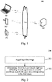
- Fig. 1 shows an example system architecture 100 in which embodiments of a method for tracking a sight line or an apparatus for tracking a sight line according to the present disclosure may be implemented.
- the system architecture 100 may include terminal devices 101, 102, and 103, a network 104, and a server 105.
- the network 104 serves as a medium providing a communication link between the terminal devices 101, 102, and 103, and the server 105.
- the network 104 may include various types of connections, such as wired or wireless communication links, or optical cables.
- a user may interact with the server 105 using the terminal devices 101, 102, and 103 via the network 104, for example, to receive or send information.
- the terminal devices 101, 102, and 103 may be provided with various client applications,
- the terminal devices 101, 102, and 103 may be hardware, or may be software.
- the terminal devices 101, 102, and 103 are hardware, the terminal devices may be various electronic devices, including but not limited to a smart phone, a tablet computer, a laptop portable computer, a desktop computer, and the like.
- the terminal devices 101, 102, and 103 are software, the terminal devices may be installed in the above electronic devices, or may be implemented as a plurality of software programs or software modules, or may be implemented as a single software program or software module. This is not specifically limited here.
- the server 105 may provide various services. For example, the server 105 may analyze and process a first image acquired from the terminal devices 101, 102, and 103, and generate a processing result (e.g., a gaze area).
- a processing result e.g., a gaze area
- the server 105 may be hardware, or may be software.
- the server may be implemented as a distributed server cluster composed of a plurality of servers, or may be implemented as a single server.
- the server 105 is software, the server may be implemented as a plurality of software programs or software modules (e.g., software programs or software modules for providing distributed services), or may be implemented as a single software program or software module. This is not specifically limited here.
- the method for tracking a sight line is generally executed by the server 105. Accordingly, the apparatus for tracking a sight line is generally provided in the server 105.
- terminal devices network, and server in Fig. 1 are merely illustrative. Any number of terminal devices, networks, and servers may be provided based on actual requirements.
- the method for tracking a sight line includes the following steps:
- Step 201 acquiring a first image.
- an executing body e.g., the server 105 shown in Fig. 1
- the method for tracking a sight line may acquire the first image, where the first image is an image of an eyeball state of a driver.
- the first image may be acquired by an image sensor in a vehicle of the driver.
- the image sensor in the present embodiment is a camera sensor (hereinafter referred to as a camera), or may be other image sensors according to actual situations. This is not limited in the present disclosure.
- the camera may take an image of an eyeball state of the driver in real time.
- Step 202 determining, based on a pre-trained sight line calibrating model, a gaze area in a world coordinate system, the gaze area corresponding to the first image.
- the executing body may determine, based on the pre-trained sight line calibrating model, the gaze area in the world coordinate system, the gaze area corresponding to the first image.
- the sight line calibrating model may be a pre-trained model, and the first image representing the eyeball state of the driver is inputted into the pre-trained sight line calibrating model to determine a gaze direction of the driver corresponding to the first image, and then based on the determined gaze direction, the gaze area corresponding to the first image in the world coordinate system is determined, where the gaze area is a to-be-finally-determined area of interest of the driver, thereby realizing the tracking of the sight line of the driver.
- the world coordinate system is an absolute coordinate system of a system. Before a user coordinate system is established, respective positions of coordinates of all points on a screen are determined based on the origin of the word coordinate system.
- a method for tracking a sight line includes first acquiring a first image representing an eyeball state of a driver; and then determining, based on a pre-trained sight line calibrating model, a gaze area in a world coordinate system, the gaze area corresponding to the first image.
- the present disclosure provides a method for tracking a sight line, which can calibrate a sight line of a driver based on a pre-trained sight line calibrating model, thereby realizing tracking of an object in the sight line of the driver, and improving the accuracy of tracking the sight line.
- Fig. 3 shows a process 300 of another embodiment of the method for tracking a sight line according to the present disclosure.
- the method for tracking a sight line includes the following steps: Step 301: acquiring a first image.
- Step 301 is substantially consistent with step 201 in the above embodiments, and a specific implementation of step 301 may be referred to the above description of step 201, and is not repeated here.
- Step 302 inputting the first image into a pre-trained sight line calibrating model to obtain a direction of a sight line corresponding to the first image.
- an executing body e.g., the server 105 shown in Fig. 1
- the method for tracking a sight line may input the first image into the pre-trained sight line calibrating model, thereby obtaining the direction of the sight line corresponding to the first image.
- the first image representing the eyeball state of the driver is inputted into the pre-trained sight line calibrating model, thereby obtaining the direction of the sight line corresponding to the first image, and then determining the direction of the sight line of the driver at this time.
- Step 303 determining a gaze area in a world coordinate system, the gaze area corresponding to the direction of the sight line.
- the executing body may determine the gaze area in the world coordinate system, the gaze area corresponding to the direction of the sight line.
- the world coordinate system is a coordinate system in the real world.
- the gaze area in a real coordinate system may be determined based on the direction of the sight line, and the gaze area corresponds to the direction of the sight line. For example, when the direction of the sight line of the driver is determined to be the left front direction, an area corresponding to the left front left direction in the world coordinate system may be determined to be the gaze area of the driver.
- the method for tracking a sight line in the present embodiment highlights the steps of training a sight line calibrating model, determining a direction of a sight line corresponding to a first image based on the sight line calibrating model, and then determining a gaze area corresponding to the direction of the sight line in a world coordinate system.
- This method improves the accuracy of the sight line calibration and has a wider range of applications.
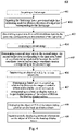
- Fig. 4 shows a process 400 of still another embodiment of the method for tracking a sight line according to the present disclosure.
- the method for tracking a sight line includes the following steps: Step 401: acquiring a first image.
- Step 402 inputting the first image into a pre-trained sight line calibrating model to obtain a direction of a sight line corresponding to the first image.
- Step 403 determining a gaze area in a world coordinate system, the gaze area corresponding to the direction of the sight line.
- Steps 401 to 403 are substantially consistent with steps 301 to 303 in the above embodiments, and specific implementations of steps 401 to 403 may be referred to the above description of steps 301 to 303, and are not repeated here.
- Step 404 acquiring a second image.
- an executing body e.g., the server 105 shown in Fig. 1
- the method for tracking a sight line may acquire the second image, where the second image is an image of a surrounding environment of a vehicle of a driver.
- the second image may be collected by another camera in the vehicle of the driver, i.e., two cameras may be installed within the vehicle of the driver, one of the cameras may internally collect the image of the eyeball state of the driver, and the other camera may collect the image of the surrounding environment of the vehicle of the driver.
- two cameras may be installed within the vehicle of the driver, one of the cameras may internally collect the image of the eyeball state of the driver, and the other camera may collect the image of the surrounding environment of the vehicle of the driver.
- other number of cameras may alternatively be provided according to the actual situations. This is not specifically limited in the present disclosure.
- the second image may contain buildings on both sides of a road on which the vehicle is traveling, and may also contain, e.g., obstacles.
- Step 405 determining a second target area in the second image, the second target area corresponding to the gaze area based on a corresponding relationship between the world coordinate system and an image coordinate system corresponding to the second image.
- the executing body may determine the second target area in the second image, the second target area corresponding to the gaze area, based on the corresponding relationship between the world coordinate system and the image coordinate system corresponding to the second image.
- the second image is an image of an object in a real environment
- the second image corresponds to the world coordinate system.
- the second target area is an area in the second image, the area corresponding to the direction of the sight line of the driver.
- a digital image collected by the camera may be stored as an array in a computer, and the value of each element (pixel) in the array is brightness (grayscale) of the image point.
- a rectangular coordinate system u-v is defined on the image, and coordinates (u, v) of each pixel are the row number and line number of each pixel in the array. Therefore, (u, v) are the coordinates of the image coordinate system in a unit of a pixel.
- Step 406 determining an object of POI in the second target area.
- the executing body may determine the object of POI (point of interest) in the second target area. Since the second target area is an area in the second image, the area corresponding to the direction of the sight line of the driver, the second target area is an area at which the driver looks. Then, a target object in the second area is the object of POI in the present embodiment, i.e., an object at which the driver looks. Therefore, the executing body may determine the object of POI in the second target area.
- the method for tracking a sight line further includes: acquiring information of a current position of the vehicle; and acquiring attribute information of the object of POI based on the information of the current position.
- the executing body may acquire the information of the current position of the vehicle.
- the information of the current position may be obtained by a GPS (global positioning system) of the vehicle, or by an IMU (inertial measurement unit) sensor of the vehicle. This is not specifically limited in the present disclosure.
- Current geographic position information may be coordinates of the current position in the world coordinate system.
- the attribute information of the object of POI is acquired based on the acquired information of the current position.
- the attribute information of the object of POI may be acquired from a map based on the coordinates of the current position.
- the attribute information may include, e.g., name and category information of the object of POI.
- the attribute information of the object of POI may alternatively be acquired, so as to feed back more comprehensive information to the driver.
- Step 407 determining, based on a corresponding relationship between the image coordinate system and a display coordinate system corresponding to a head up display screen, a target display position of the object of POI on the head up display screen.
- the executing body may determine, based on the corresponding relationship between the image coordinate system and the display coordinate system corresponding to the head up display screen, the target display position of the object of POI on the head up display screen.
- the head up display screen is projected by a head up display device, and there is also a corresponding display coordinate system in the head up display screen. Since the object of POI is an object in the second image, and there is also a corresponding relationship between the display coordinate system and the image coordinate system corresponding to the second image, the executing body may determine the target display position of the object of POI on the head up display screen based on the corresponding relationship between the display coordinate system and the image coordinate system, and display the object of POI at the target display position.
- Step 408 displaying the object of POI at the target display position on the head up display screen.
- the executing body may display the object of POI at the target display position on the head up display screen, and superimposedly display the attribute information on the object of POI on the head up display picture. Since the target display position should correspond to position information of the object of POI in reality (i.e., the position information in the second image), after the target display position of the object of POI is determined, the head up display device may project the POI onto the target display position, thereby more intuitively and accurately displaying the object of POI to the driver.
- Step 409 superimposedly displaying attribute information on the object of POI on the head up display screen.
- the executing body may superimposedly display the attribute information of the object of POI on the object of POI, thereby exactly fusing the attribute information with a real building, and achieving the effect of augmented reality.
- the executing body may render the shopping mall at the target display position, and superimposedly display, e.g., the name of the shopping mall and activity information in the shopping mall on the object of POI.
- the method for tracking a sight line in the present embodiment further: acquires a second image, determines a second target area in the second image, the second target area corresponding to a gaze area based on a corresponding relationship between a world coordinate system and an image coordinate system corresponding to the second image, and then determines an object of POI in the second target area; then acquires information of a current position of a vehicle, and acquires attribute information of the object of POI based on the information of the current position; and finally determines, based on a corresponding relationship between the image coordinate system and a display coordinate system corresponding to a head up display screen, a target display position of the object of POI on the head up display screen, displays the object of POI at the target display position on the head up display screen, and superimposedly displays the attribute information on the object of POI on the head up display screen, thereby positioning and tracking the object based on a sight line of a driver,
- the acquisition, storage, and application of personal information of a user involved are in conformity with relevant laws and regulations, and does not violate public order and good customs.
- the method for training a model includes the following steps: Step 501: acquiring a training sample set.
- an executing body e.g., the server 105 shown in Fig. 1
- the method for training a model may acquire the training sample set, where a training sample in the training sample set includes an image of an eyeball state of a driver when the driver looks at a label point, and position information of the label point.
- a calibration plate when acquiring the training sample set, a calibration plate may be provided, and the calibration plate may be presented on a head up display screen projected by a head up display device, where the calibration plate may be divided into different areas in advance, each area has corresponding position information, and a resolution of the calibration plate should be consistent with a resolution of the head up display device.
- the resolutions of the calibration plate and the head up display device are 854 ⁇ 480.
- the calibration plate may alternatively be a checkerboard. This is not specifically limited in the present embodiment.
- an experimenter may be asked to sit at the driver's seat (or, the driver may alternatively perform the experiment directly) with his eyes looking at different data on the calibration plate, i.e., looking at different areas on the calibration target, to collect images of eyeball states of the experimenter while the experimenter looks at different areas, thereby obtaining a training sample set for training a sight line calibrating model.
- the training sample set includes the images of the eyeball states of the driver when the driver looks at label points, and the position information of the label points, where the position information of the label points may be manually labeled, for example, the position information is labeled as five lines and three rows.
- Step 502 using the image of the eyeball state as an input, and using the position information as an output, to obtain a sight line calibrating model by training.
- the executing body may use the image of the eyeball state as the input, and use the position information as the output, to obtain the sight line calibrating model by training.
- the training sample set After acquiring the training sample set, the training sample set is inputted into a deep learning model to train the deep learning model, thereby obtaining a trained sight line calibrating model.
- An input of the sight line calibrating model is an image of an eyeball state of the driver
- an output of the sight line calibrating model is position information corresponding to the image of the eyeball state of the driver.
- An existing model may be used as the deep learning model. This is not specifically limited in the present disclosure.
- the method for training a model provided in an embodiment of the present disclosure first acquires a training sample set; and then uses images of eyeball states as input, and uses position information as output, to obtain a sight line calibrating model by training.
- the present disclosure provides a method for training a model. The method can obtain a sight line calibrating model by training, such that the sight line calibration result is more accurate.
- an embodiment of the present disclosure provides an apparatus for tracking a sight line.
- the embodiment of the apparatus corresponds to the embodiment of the method shown in Fig. 2 , and the apparatus may be specifically applied to various electronic devices.
- the apparatus 600 for tracking a sight line of the present embodiment may include: a first acquiring module 601 and a first determining module 602.
- the first acquiring module 601 is configured to acquire a first image, where the first image is an image of an eyeball state of a driver; and the first determining module 602 is configured to determine, based on a pre-trained sight line calibrating model, a gaze area in a world coordinate system, the gaze area corresponding to the first image.
- the first determining module includes: an input submodule configured to input the first image into the pre-trained sight line calibrating model to obtain a direction of a sight line corresponding to the first image; and a determining submodule configured to determine the gaze area in the world coordinate system, the gaze area corresponding to the direction of the sight line.
- the apparatus for tracking a sight line further includes: a second acquiring module configured to acquire a second image, where the second image is an image of a surrounding environment of a vehicle of the driver; and a second determining module configured to determine a second target area in the second image, the second target area corresponding to the gaze area, based on a corresponding relationship between the world coordinate system and an image coordinate system corresponding to the second image.
- the apparatus for tracking a sight line further includes: a third determining module configured to determine an object of point of interest (POI) in the second target area; and a fourth determining module configured to determine, based on a corresponding relationship between the image coordinate system and a display coordinate system corresponding to a head up display screen, a target display position of the object of POI on the head up display screen.
- POI point of interest
- the apparatus for tracking a sight line further includes: a third acquiring module configured to acquire information of a current position of the vehicle; a fourth acquiring module configured to acquire attribute information of the object of POI based on the information of the current position; and a display module configured to superimposedly display the attribute information on the object of POI on the head up display screen.
- an embodiment of the present disclosure provides an apparatus for training a model.
- the embodiment of the apparatus corresponds to the embodiment of the method shown in Fig. 5 , and the apparatus may be specifically applied to various electronic devices.
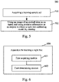
- the apparatus 700 for training a model of the present embodiment may include: a fifth acquiring module 701 and a training module 702.
- the fifth acquiring module 701 is configured to acquire a training sample set, where a training sample in the training sample set includes an image of an eyeball state of a driver when the driver looks at a label point, and position information of the label point; and the training module 702 is configured to use the image of the eyeball state as an input, and use the position information as an output, to obtain a sight line calibrating model by training.
- the present disclosure further provides an electronic device, a readable storage medium, and a computer program product.
- Fig. 8 shows a schematic block diagram of an example electronic device 800 that may be configured to implement embodiments of the present disclosure.
- the electronic device is intended to represent various forms of digital computers, such as a laptop computer, a desktop computer, a workbench, a personal digital assistant, a server, a blade server, a mainframe computer, and other suitable computers.
- the electronic device may alternatively represent various forms of mobile apparatuses, such as a personal digital assistant, a cellular phone, a smart phone, a wearable device, and other similar computing apparatuses.
- the components shown herein, the connections and relationships thereof, and the functions thereof are used as examples only, and are not intended to limit implementations of the present disclosure described and/or claimed herein.
- the device 800 includes a computing unit 801, which may execute various appropriate actions and processes in accordance with a computer program stored in a read-only memory (ROM) 802 or a computer program loaded into a random access memory (RAM) 803 from a storage unit 808.
- the RAM 803 may further store various programs and data required by operations of the device 800.
- the computing unit 801, the ROM 802, and the RAM 803 are connected to each other through a bus 804.
- An input/output (I/O) interface 805 is also connected to the bus 804.
- a plurality of components in the device 800 is connected to the I/O interface 805, including: an input unit 806, such as a keyboard and a mouse; an output unit 807, such as various types of sight line trackers and speakers; a storage unit 808, such as a magnetic disk and an optical disk; and a communication unit 809, such as a network card, a modem, and a wireless communication transceiver.
- the communication unit 809 allows the device 800 to exchange information/data with other devices through a computer network such as the Internet and/or various telecommunication networks.
- the computing unit 801 may be various general purpose and/or specific purpose processing components having a processing capability and a computing capability. Some examples of the computing unit 801 include, but are not limited to, a central processing unit (CPU), a graphics processing unit (GPU), various special purpose artificial intelligence (AI) computing chips, various computing units running a machine learning model algorithm, a digital signal processor (DSP), and any appropriate processor, controller, micro-controller, and the like.
- the computing unit 801 executes various methods and processes described above, such as the method for tracking a sight line.
- the method for tracking a sight line maybe implemented in a computer software program that is tangibly included in a machine readable medium, such as the storage unit 808.
- some or all of the computer programs may be loaded and/or installed onto the device 800 via the ROM 802 and/or the communication unit 809.
- the computer program When the computer program is loaded into the RAM 803 and executed by the computing unit 801, one or more steps of the method for tracking a sight line described above may be executed.
- the computing unit 801 may be configured to execute the method for tracking a sight line by any other appropriate approach (e.g., by means of firmware).
- Various implementations of the systems and technologies described above herein may be implemented in a digital electronic circuit system, an integrated circuit system, a field programmable gate array (FPGA), an application specific integrated circuit (ASIC), an application specific standard product (ASSP), a system on a chip (SOC), a complex programmable logic device (CPLD), computer hardware, firmware, software, and/or a combination thereof.
- FPGA field programmable gate array
- ASIC application specific integrated circuit
- ASSP application specific standard product
- SOC system on a chip
- CPLD complex programmable logic device
- the various implementations may include: being implemented in one or more computer programs, where the one or more computer programs may be executed and/or interpreted on a programmable system including at least one programmable processor, and the programmable processor may be a specific-purpose or general-purpose programmable processor, which may receive data and instructions from a storage system, at least one input apparatus and at least one output apparatus, and send the data and instructions to the storage system, the at least one input apparatus and the at least one output apparatus.
- Program code for implementing the method of the present disclosure may be compiled using one or any combination of more programming languages.
- the program code may be provided to a processor or controller of a general purpose computer, a specific purpose computer, or other programmable apparatuses for tracking a slight line, such that the program code, when executed by the processor or controller, causes the functions/operations specified in the flowcharts and/or block diagrams to be implemented.
- the program code may be completely executed on a machine, partially executed on a machine, partially executed on a machine and partially executed on a remote machine as a separate software package, or completely executed on a remote machine or server.
- a machine readable medium may be a tangible medium which may contain or store a program for use by, or used in combination with, an instruction execution system, apparatus or device.
- the machine readable medium may be a machine readable signal medium or a machine readable storage medium.
- the computer readable medium may include, but is not limited to, electronic, magnetic, optical, electromagnetic, infrared, or semiconductor systems, apparatuses, or devices, or any appropriate combination of the above.
- a more specific example of the machine readable storage medium will include an electrical connection based on one or more pieces of wire, a portable computer disk, a hard disk, a random access memory (RAM), a read only memory (ROM), an erasable programmable read only memory (EPROM or flash memory), an optical fiber, a portable compact disk read only memory (CD-ROM), an optical storage device, a magnetic storage device, or any appropriate combination of the above.
- a portable computer disk a hard disk, a random access memory (RAM), a read only memory (ROM), an erasable programmable read only memory (EPROM or flash memory), an optical fiber, a portable compact disk read only memory (CD-ROM), an optical storage device, a magnetic storage device, or any appropriate combination of the above.
- the systems and technologies described herein may be implemented on a computer that is provided with: an apparatus for tracking a slight line (e.g., a CRT (cathode ray tube) or an LCD (liquid crystal display) monitor) configured to provide sight line tracking information to the user; and a keyboard and a pointing apparatus (e.g., a mouse or a trackball) by which the user can provide an input to the computer.
- a slight line e.g., a CRT (cathode ray tube) or an LCD (liquid crystal display) monitor
- a keyboard and a pointing apparatus e.g., a mouse or a trackball
- Other kinds of apparatuses may also be configured to provide interaction with the user.
- feedback provided to the user may be any form of sensory feedback (e.g., visual feedback, auditory feedback, or tactile feedback); and an input may be received from the user in any form (including an acoustic input, a voice input, or a tactile input).
- sensory feedback e.g., visual feedback, auditory feedback, or tactile feedback
- an input may be received from the user in any form (including an acoustic input, a voice input, or a tactile input).
- the systems and technologies described herein may be implemented in a computing system that includes a back-end component (e.g., as a data server), or a computing system that includes a middleware component (e.g., an application server), or a computing system that includes a front-end component (e.g., a user computer with a graphical user interface or a web browser through which the user can interact with an implementation of the systems and technologies described herein), or a computing system that includes any combination of such a back-end component, such a middleware component, or such a front-end component.
- the components of the system may be interconnected by digital data communication (e.g., a communication network) in any form or medium. Examples of the communication network include: a local area network (LAN), a wide area network (WAN), and the Internet.
- the computer system may include a client and a server.
- the client and the server are generally remote from each other, and generally interact with each other through a communication network.
- the relationship between the client and the server is generated by virtue of computer programs that run on corresponding computers and have a client-server relationship with each other.
- the server may be a cloud server, a distributed system server, or a server combined with a blockchain.
Landscapes
- Engineering & Computer Science (AREA)
- Theoretical Computer Science (AREA)
- Physics & Mathematics (AREA)
- General Physics & Mathematics (AREA)
- General Engineering & Computer Science (AREA)
- Human Computer Interaction (AREA)
- Multimedia (AREA)
- Computer Vision & Pattern Recognition (AREA)
- Data Mining & Analysis (AREA)
- Optics & Photonics (AREA)
- Artificial Intelligence (AREA)
- Evolutionary Computation (AREA)
- General Health & Medical Sciences (AREA)
- Health & Medical Sciences (AREA)
- Evolutionary Biology (AREA)
- Bioinformatics & Computational Biology (AREA)
- Life Sciences & Earth Sciences (AREA)
- Bioinformatics & Cheminformatics (AREA)
- Databases & Information Systems (AREA)
- Medical Informatics (AREA)
- Software Systems (AREA)
- Computing Systems (AREA)
- Ophthalmology & Optometry (AREA)
- User Interface Of Digital Computer (AREA)
- Image Analysis (AREA)
- Traffic Control Systems (AREA)
- Processing Or Creating Images (AREA)
- Image Processing (AREA)
- Eye Examination Apparatus (AREA)
Applications Claiming Priority (1)
| Application Number | Priority Date | Filing Date | Title |
|---|---|---|---|
| CN202110709957.3A CN113420678A (zh) | 2021-06-25 | 2021-06-25 | 视线追踪方法、装置、设备、存储介质以及计算机程序产品 |
Publications (2)
| Publication Number | Publication Date |
|---|---|
| EP4040405A2 true EP4040405A2 (de) | 2022-08-10 |
| EP4040405A3 EP4040405A3 (de) | 2022-12-14 |
Family
ID=77716691
Family Applications (1)
| Application Number | Title | Priority Date | Filing Date |
|---|---|---|---|
| EP22179224.5A Withdrawn EP4040405A3 (de) | 2021-06-25 | 2022-06-15 | Verfahren und gerät zur sichtlinien-verfolgung, vorrichtung, speichermedium und computerprogrammprodukt |
Country Status (5)
| Country | Link |
|---|---|
| US (1) | US20220309702A1 (de) |
| EP (1) | EP4040405A3 (de) |
| JP (1) | JP7339386B2 (de) |
| KR (1) | KR20220054754A (de) |
| CN (1) | CN113420678A (de) |
Families Citing this family (16)
| Publication number | Priority date | Publication date | Assignee | Title |
|---|---|---|---|---|
| CN113865610A (zh) * | 2021-09-30 | 2021-12-31 | 北京百度网讯科技有限公司 | 用于生成导航信息的方法、装置、设备、介质和产品 |
| CN114302054B (zh) * | 2021-11-30 | 2023-06-20 | 歌尔科技有限公司 | 一种ar设备的拍照方法及其ar设备 |
| CN114067420B (zh) * | 2022-01-07 | 2023-02-03 | 深圳佑驾创新科技有限公司 | 一种基于单目摄像头的视线测量方法及装置 |
| CN115116039A (zh) * | 2022-01-14 | 2022-09-27 | 长城汽车股份有限公司 | 一种车辆座舱外视线追踪方法、装置、车辆和存储介质 |
| CN114715175B (zh) * | 2022-05-06 | 2025-04-25 | Oppo广东移动通信有限公司 | 目标对象的确定方法、装置、电子设备以及存储介质 |
| WO2023226034A1 (zh) * | 2022-05-27 | 2023-11-30 | 京东方科技集团股份有限公司 | 视线标定系统、方法、设备和非瞬态计算机可读存储介质 |
| CN115097933A (zh) * | 2022-06-13 | 2022-09-23 | 华能核能技术研究院有限公司 | 专注度的确定方法、装置、计算机设备和存储介质 |
| CN115830675B (zh) * | 2022-11-28 | 2023-07-07 | 深圳市华弘智谷科技有限公司 | 一种注视点跟踪方法、装置、智能眼镜及存储介质 |
| CN115761249B (zh) * | 2022-12-28 | 2024-02-23 | 北京曼恒数字技术有限公司 | 一种图像处理方法、系统、电子设备及计算机程序产品 |
| CN116189507B (zh) * | 2023-02-02 | 2025-10-28 | 北京东方瑞丰航空技术有限公司 | 一种基于vr设备的飞行员训练方法、系统和设备 |
| CN116481424A (zh) * | 2023-04-07 | 2023-07-25 | 阿波罗智联(北京)科技有限公司 | 物体坐标的确定方法、装置、设备和介质 |
| CN116486386A (zh) * | 2023-04-24 | 2023-07-25 | 上海临港绝影智能科技有限公司 | 一种视线分心范围确定方法和装置 |
| CN116597425B (zh) * | 2023-05-24 | 2024-04-05 | 无锡车联天下信息技术有限公司 | 一种驾驶员的样本标签数据的确定方法、装置及电子设备 |
| CN117213422A (zh) * | 2023-09-06 | 2023-12-12 | 深圳市瀚思通汽车电子有限公司 | 坐标测量眼镜、坐标测量方法、装置、设备及其存储介质 |
| CN117218924A (zh) * | 2023-09-19 | 2023-12-12 | 北京麦课在线教育技术有限责任公司 | 一种基于vr驾驶的数字人交互驾驶培训系统 |
| US20260065545A1 (en) * | 2024-08-28 | 2026-03-05 | Maplebear Inc. | Using a visual language model and a generative artificial intelligence model to evaluate and correct an image of a collection of items |
Citations (3)
| Publication number | Priority date | Publication date | Assignee | Title |
|---|---|---|---|---|
| JPH07257228A (ja) * | 1994-03-18 | 1995-10-09 | Nissan Motor Co Ltd | 車両用表示装置 |
| JP2015077876A (ja) * | 2013-10-16 | 2015-04-23 | 株式会社デンソー | ヘッドアップディスプレイ装置 |
| EP3828755A1 (de) * | 2019-11-29 | 2021-06-02 | Veoneer Sweden AB | Verbesserte schätzung der fahreraufmerksamkeit |
Family Cites Families (8)
| Publication number | Priority date | Publication date | Assignee | Title |
|---|---|---|---|---|
| JPH0755941A (ja) * | 1993-08-11 | 1995-03-03 | Nissan Motor Co Ltd | 車間距離測定装置 |
| KR101923672B1 (ko) * | 2015-06-15 | 2018-11-30 | 서울바이오시스 주식회사 | 헤드램프 장치 및 그 조명 제어 방법 |
| CN109835260B (zh) * | 2019-03-07 | 2023-02-03 | 百度在线网络技术(北京)有限公司 | 一种车辆信息显示方法、装置、终端和存储介质 |
| CN109917920B (zh) * | 2019-03-14 | 2023-02-24 | 阿波罗智联(北京)科技有限公司 | 车载投射处理方法、装置、车载设备及存储介质 |
| CN110148224B (zh) * | 2019-04-04 | 2020-05-19 | 精电(河源)显示技术有限公司 | Hud图像显示方法、装置及终端设备 |
| US11636609B2 (en) | 2019-12-16 | 2023-04-25 | Nvidia Corporation | Gaze determination machine learning system having adaptive weighting of inputs |
| US11487968B2 (en) | 2019-12-16 | 2022-11-01 | Nvidia Corporation | Neural network based facial analysis using facial landmarks and associated confidence values |
| CN111767844B (zh) * | 2020-06-29 | 2023-12-29 | 阿波罗智能技术(北京)有限公司 | 用于三维建模的方法和装置 |
-
2021
- 2021-06-25 CN CN202110709957.3A patent/CN113420678A/zh active Pending
-
2022
- 2022-03-29 JP JP2022053479A patent/JP7339386B2/ja active Active
- 2022-04-15 KR KR1020220046677A patent/KR20220054754A/ko not_active Withdrawn
- 2022-06-15 EP EP22179224.5A patent/EP4040405A3/de not_active Withdrawn
- 2022-06-16 US US17/842,484 patent/US20220309702A1/en not_active Abandoned
Patent Citations (3)
| Publication number | Priority date | Publication date | Assignee | Title |
|---|---|---|---|---|
| JPH07257228A (ja) * | 1994-03-18 | 1995-10-09 | Nissan Motor Co Ltd | 車両用表示装置 |
| JP2015077876A (ja) * | 2013-10-16 | 2015-04-23 | 株式会社デンソー | ヘッドアップディスプレイ装置 |
| EP3828755A1 (de) * | 2019-11-29 | 2021-06-02 | Veoneer Sweden AB | Verbesserte schätzung der fahreraufmerksamkeit |
Also Published As
| Publication number | Publication date |
|---|---|
| US20220309702A1 (en) | 2022-09-29 |
| KR20220054754A (ko) | 2022-05-03 |
| JP7339386B2 (ja) | 2023-09-05 |
| JP2022088529A (ja) | 2022-06-14 |
| CN113420678A (zh) | 2021-09-21 |
| EP4040405A3 (de) | 2022-12-14 |
Similar Documents
| Publication | Publication Date | Title |
|---|---|---|
| EP4040405A2 (de) | Verfahren und vorrichtung zur verfolgung von sichtlinie, einrichtung, speichermedium und computerprogrammprodukt | |
| EP4116462A2 (de) | Verfahren und vorrichtung zur bildverarbeitung, elektronische vorrichtung, speichermedium und programmprodukt | |
| EP4057127A2 (de) | Anzeigeverfahren, anzeigegerät, vorrichtung, speichermedium und computerprogrammprodukt | |
| US10832084B2 (en) | Dense three-dimensional correspondence estimation with multi-level metric learning and hierarchical matching | |
| CN114140759B (zh) | 高精地图车道线位置确定方法、装置及自动驾驶车辆 | |
| US20230162383A1 (en) | Method of processing image, device, and storage medium | |
| CN110109535A (zh) | 增强现实生成方法及装置 | |
| US11610287B2 (en) | Motion trail update method, head-mounted display device and computer-readable medium | |
| EP4194807A1 (de) | Verfahren und vorrichtung zur konstruktion einer hochpräzisen karte, elektronische vorrichtung und speichermedium | |
| US20230206595A1 (en) | Three-dimensional data augmentation method, model training and detection method, device, and autonomous vehicle | |
| KR20220100813A (ko) | 자율주행 차량 정합 방법, 장치, 전자 기기 및 차량 | |
| CN114186007A (zh) | 高精地图生成方法、装置、电子设备和存储介质 | |
| US20230169680A1 (en) | Beijing baidu netcom science technology co., ltd. | |
| EP4086102A2 (de) | Navigationsverfahren und -vorrichtung, elektronische vorrichtung, lesbares speichermedium und computerprogrammprodukt | |
| CN116844129A (zh) | 多模态特征对齐融合的路侧目标检测方法、系统及装置 | |
| CN112037316B (zh) | 映射的生成方法、装置和路侧设备 | |
| CN112507951A (zh) | 指示灯识别方法、装置、设备、路侧设备和云控平台 | |
| CN111260722A (zh) | 车辆定位方法、设备及存储介质 | |
| CN113869147B (zh) | 目标检测方法及装置 | |
| CN111914861A (zh) | 目标检测方法和装置 | |
| US11216977B2 (en) | Methods and apparatuses for outputting information and calibrating camera | |
| CN113592980B (zh) | 招牌拓扑关系的构建方法、装置、电子设备和存储介质 | |
| CN114166231A (zh) | 众包数据采集方法、装置、设备、存储介质以及程序产品 | |
| CN115077539A (zh) | 一种地图生成方法、装置、设备以及存储介质 | |
| CN110389349B (zh) | 定位方法和装置 |
Legal Events
| Date | Code | Title | Description |
|---|---|---|---|
| PUAI | Public reference made under article 153(3) epc to a published international application that has entered the european phase |
Free format text: ORIGINAL CODE: 0009012 |
|
| STAA | Information on the status of an ep patent application or granted ep patent |
Free format text: STATUS: REQUEST FOR EXAMINATION WAS MADE |
|
| 17P | Request for examination filed |
Effective date: 20220615 |
|
| AK | Designated contracting states |
Kind code of ref document: A2 Designated state(s): AL AT BE BG CH CY CZ DE DK EE ES FI FR GB GR HR HU IE IS IT LI LT LU LV MC MK MT NL NO PL PT RO RS SE SI SK SM TR |
|
| PUAL | Search report despatched |
Free format text: ORIGINAL CODE: 0009013 |
|
| AK | Designated contracting states |
Kind code of ref document: A3 Designated state(s): AL AT BE BG CH CY CZ DE DK EE ES FI FR GB GR HR HU IE IS IT LI LT LU LV MC MK MT NL NO PL PT RO RS SE SI SK SM TR |
|
| RIC1 | Information provided on ipc code assigned before grant |
Ipc: G06V 40/18 20220101AFI20221109BHEP |
|
| STAA | Information on the status of an ep patent application or granted ep patent |
Free format text: STATUS: EXAMINATION IS IN PROGRESS |
|
| 17Q | First examination report despatched |
Effective date: 20230809 |
|
| STAA | Information on the status of an ep patent application or granted ep patent |
Free format text: STATUS: THE APPLICATION IS DEEMED TO BE WITHDRAWN |
|
| 18D | Application deemed to be withdrawn |
Effective date: 20240312 |