EP4040623A1 - Système modulaire de stockage par batteries avec modules d'accumulation d'énergie rechargeables et procédés de fonctionnement du système d'accumulateur de batterie - Google Patents
Système modulaire de stockage par batteries avec modules d'accumulation d'énergie rechargeables et procédés de fonctionnement du système d'accumulateur de batterie Download PDFInfo
- Publication number
- EP4040623A1 EP4040623A1 EP21155140.3A EP21155140A EP4040623A1 EP 4040623 A1 EP4040623 A1 EP 4040623A1 EP 21155140 A EP21155140 A EP 21155140A EP 4040623 A1 EP4040623 A1 EP 4040623A1
- Authority
- EP
- European Patent Office
- Prior art keywords
- energy storage
- storage modules
- storage system
- battery storage
- pulse width
- Prior art date
- Legal status (The legal status is an assumption and is not a legal conclusion. Google has not performed a legal analysis and makes no representation as to the accuracy of the status listed.)
- Pending
Links
Images

Classifications
-
- H—ELECTRICITY
- H02—GENERATION; CONVERSION OR DISTRIBUTION OF ELECTRIC POWER
- H02J—ELECTRIC POWER NETWORKS; CIRCUIT ARRANGEMENTS OR SYSTEMS FOR SUPPLYING OR DISTRIBUTING ELECTRIC POWER; SYSTEMS FOR STORING ELECTRIC ENERGY
- H02J7/00—Circuit arrangements for charging or discharging batteries or for supplying loads from batteries
- H02J7/50—Circuit arrangements for charging or discharging batteries or for supplying loads from batteries acting upon multiple batteries simultaneously or sequentially
- H02J7/575—Parallel/serial switching of connection of batteries to charge or load circuit
-
- H—ELECTRICITY
- H02—GENERATION; CONVERSION OR DISTRIBUTION OF ELECTRIC POWER
- H02J—ELECTRIC POWER NETWORKS; CIRCUIT ARRANGEMENTS OR SYSTEMS FOR SUPPLYING OR DISTRIBUTING ELECTRIC POWER; SYSTEMS FOR STORING ELECTRIC ENERGY
- H02J3/00—Circuit arrangements for AC mains or AC distribution networks
- H02J3/28—Arrangements for balancing of the load in networks by storage of energy
- H02J3/32—Arrangements for balancing of the load in networks by storage of energy using batteries or super capacitors with converting means
-
- B—PERFORMING OPERATIONS; TRANSPORTING
- B60—VEHICLES IN GENERAL
- B60L—PROPULSION OF ELECTRICALLY-PROPELLED VEHICLES; SUPPLYING ELECTRIC POWER FOR AUXILIARY EQUIPMENT OF ELECTRICALLY-PROPELLED VEHICLES; ELECTRODYNAMIC BRAKE SYSTEMS FOR VEHICLES IN GENERAL; MAGNETIC SUSPENSION OR LEVITATION FOR VEHICLES; MONITORING OPERATING VARIABLES OF ELECTRICALLY-PROPELLED VEHICLES; ELECTRIC SAFETY DEVICES FOR ELECTRICALLY-PROPELLED VEHICLES
- B60L15/00—Methods, circuits, or devices for controlling the traction-motor speed of electrically-propelled vehicles
- B60L15/02—Methods, circuits, or devices for controlling the traction-motor speed of electrically-propelled vehicles characterised by the form of the current used in the control circuit
- B60L15/08—Methods, circuits, or devices for controlling the traction-motor speed of electrically-propelled vehicles characterised by the form of the current used in the control circuit using pulses
-
- B—PERFORMING OPERATIONS; TRANSPORTING
- B60—VEHICLES IN GENERAL
- B60L—PROPULSION OF ELECTRICALLY-PROPELLED VEHICLES; SUPPLYING ELECTRIC POWER FOR AUXILIARY EQUIPMENT OF ELECTRICALLY-PROPELLED VEHICLES; ELECTRODYNAMIC BRAKE SYSTEMS FOR VEHICLES IN GENERAL; MAGNETIC SUSPENSION OR LEVITATION FOR VEHICLES; MONITORING OPERATING VARIABLES OF ELECTRICALLY-PROPELLED VEHICLES; ELECTRIC SAFETY DEVICES FOR ELECTRICALLY-PROPELLED VEHICLES
- B60L53/00—Methods of charging batteries, specially adapted for electric vehicles; Charging stations or on-board charging equipment therefor; Exchange of energy storage elements in electric vehicles
- B60L53/50—Charging stations characterised by energy-storage or power-generation means
- B60L53/53—Batteries
-
- B—PERFORMING OPERATIONS; TRANSPORTING
- B60—VEHICLES IN GENERAL
- B60L—PROPULSION OF ELECTRICALLY-PROPELLED VEHICLES; SUPPLYING ELECTRIC POWER FOR AUXILIARY EQUIPMENT OF ELECTRICALLY-PROPELLED VEHICLES; ELECTRODYNAMIC BRAKE SYSTEMS FOR VEHICLES IN GENERAL; MAGNETIC SUSPENSION OR LEVITATION FOR VEHICLES; MONITORING OPERATING VARIABLES OF ELECTRICALLY-PROPELLED VEHICLES; ELECTRIC SAFETY DEVICES FOR ELECTRICALLY-PROPELLED VEHICLES
- B60L58/00—Methods or circuit arrangements for monitoring or controlling batteries or fuel cells, specially adapted for electric vehicles
- B60L58/10—Methods or circuit arrangements for monitoring or controlling batteries or fuel cells, specially adapted for electric vehicles for monitoring or controlling batteries
- B60L58/18—Methods or circuit arrangements for monitoring or controlling batteries or fuel cells, specially adapted for electric vehicles for monitoring or controlling batteries of two or more battery modules
-
- H—ELECTRICITY
- H01—ELECTRIC ELEMENTS
- H01M—PROCESSES OR MEANS, e.g. BATTERIES, FOR THE DIRECT CONVERSION OF CHEMICAL ENERGY INTO ELECTRICAL ENERGY
- H01M10/00—Secondary cells; Manufacture thereof
- H01M10/42—Methods or arrangements for servicing or maintenance of secondary cells or secondary half-cells
- H01M10/425—Structural combination with electronic components, e.g. electronic circuits integrated to the outside of the casing
-
- H—ELECTRICITY
- H01—ELECTRIC ELEMENTS
- H01M—PROCESSES OR MEANS, e.g. BATTERIES, FOR THE DIRECT CONVERSION OF CHEMICAL ENERGY INTO ELECTRICAL ENERGY
- H01M10/00—Secondary cells; Manufacture thereof
- H01M10/42—Methods or arrangements for servicing or maintenance of secondary cells or secondary half-cells
- H01M10/44—Methods for charging or discharging
- H01M10/441—Methods for charging or discharging for several batteries or cells simultaneously or sequentially
-
- H—ELECTRICITY
- H01—ELECTRIC ELEMENTS
- H01M—PROCESSES OR MEANS, e.g. BATTERIES, FOR THE DIRECT CONVERSION OF CHEMICAL ENERGY INTO ELECTRICAL ENERGY
- H01M10/00—Secondary cells; Manufacture thereof
- H01M10/60—Heating or cooling; Temperature control
- H01M10/61—Types of temperature control
- H01M10/613—Cooling or keeping cold
-
- H—ELECTRICITY
- H01—ELECTRIC ELEMENTS
- H01M—PROCESSES OR MEANS, e.g. BATTERIES, FOR THE DIRECT CONVERSION OF CHEMICAL ENERGY INTO ELECTRICAL ENERGY
- H01M50/00—Constructional details or processes of manufacture of the non-active parts of electrochemical cells other than fuel cells, e.g. hybrid cells
- H01M50/20—Mountings; Secondary casings or frames; Racks, modules or packs; Suspension devices; Shock absorbers; Transport or carrying devices; Holders
- H01M50/204—Racks, modules or packs for multiple batteries or multiple cells
-
- H—ELECTRICITY
- H01—ELECTRIC ELEMENTS
- H01M—PROCESSES OR MEANS, e.g. BATTERIES, FOR THE DIRECT CONVERSION OF CHEMICAL ENERGY INTO ELECTRICAL ENERGY
- H01M50/00—Constructional details or processes of manufacture of the non-active parts of electrochemical cells other than fuel cells, e.g. hybrid cells
- H01M50/20—Mountings; Secondary casings or frames; Racks, modules or packs; Suspension devices; Shock absorbers; Transport or carrying devices; Holders
- H01M50/218—Mountings; Secondary casings or frames; Racks, modules or packs; Suspension devices; Shock absorbers; Transport or carrying devices; Holders characterised by the material
- H01M50/22—Mountings; Secondary casings or frames; Racks, modules or packs; Suspension devices; Shock absorbers; Transport or carrying devices; Holders characterised by the material of the casings or racks
- H01M50/222—Inorganic material
- H01M50/224—Metals
-
- H—ELECTRICITY
- H01—ELECTRIC ELEMENTS
- H01M—PROCESSES OR MEANS, e.g. BATTERIES, FOR THE DIRECT CONVERSION OF CHEMICAL ENERGY INTO ELECTRICAL ENERGY
- H01M50/00—Constructional details or processes of manufacture of the non-active parts of electrochemical cells other than fuel cells, e.g. hybrid cells
- H01M50/20—Mountings; Secondary casings or frames; Racks, modules or packs; Suspension devices; Shock absorbers; Transport or carrying devices; Holders
- H01M50/218—Mountings; Secondary casings or frames; Racks, modules or packs; Suspension devices; Shock absorbers; Transport or carrying devices; Holders characterised by the material
- H01M50/22—Mountings; Secondary casings or frames; Racks, modules or packs; Suspension devices; Shock absorbers; Transport or carrying devices; Holders characterised by the material of the casings or racks
- H01M50/227—Organic material
-
- H—ELECTRICITY
- H01—ELECTRIC ELEMENTS
- H01M—PROCESSES OR MEANS, e.g. BATTERIES, FOR THE DIRECT CONVERSION OF CHEMICAL ENERGY INTO ELECTRICAL ENERGY
- H01M50/00—Constructional details or processes of manufacture of the non-active parts of electrochemical cells other than fuel cells, e.g. hybrid cells
- H01M50/20—Mountings; Secondary casings or frames; Racks, modules or packs; Suspension devices; Shock absorbers; Transport or carrying devices; Holders
- H01M50/218—Mountings; Secondary casings or frames; Racks, modules or packs; Suspension devices; Shock absorbers; Transport or carrying devices; Holders characterised by the material
- H01M50/22—Mountings; Secondary casings or frames; Racks, modules or packs; Suspension devices; Shock absorbers; Transport or carrying devices; Holders characterised by the material of the casings or racks
- H01M50/231—Mountings; Secondary casings or frames; Racks, modules or packs; Suspension devices; Shock absorbers; Transport or carrying devices; Holders characterised by the material of the casings or racks having a layered structure
-
- H—ELECTRICITY
- H01—ELECTRIC ELEMENTS
- H01M—PROCESSES OR MEANS, e.g. BATTERIES, FOR THE DIRECT CONVERSION OF CHEMICAL ENERGY INTO ELECTRICAL ENERGY
- H01M50/00—Constructional details or processes of manufacture of the non-active parts of electrochemical cells other than fuel cells, e.g. hybrid cells
- H01M50/20—Mountings; Secondary casings or frames; Racks, modules or packs; Suspension devices; Shock absorbers; Transport or carrying devices; Holders
- H01M50/258—Modular batteries; Casings provided with means for assembling
-
- H—ELECTRICITY
- H01—ELECTRIC ELEMENTS
- H01M—PROCESSES OR MEANS, e.g. BATTERIES, FOR THE DIRECT CONVERSION OF CHEMICAL ENERGY INTO ELECTRICAL ENERGY
- H01M50/00—Constructional details or processes of manufacture of the non-active parts of electrochemical cells other than fuel cells, e.g. hybrid cells
- H01M50/50—Current conducting connections for cells or batteries
- H01M50/502—Interconnectors for connecting terminals of adjacent batteries; Interconnectors for connecting cells outside a battery casing
-
- H—ELECTRICITY
- H02—GENERATION; CONVERSION OR DISTRIBUTION OF ELECTRIC POWER
- H02J—ELECTRIC POWER NETWORKS; CIRCUIT ARRANGEMENTS OR SYSTEMS FOR SUPPLYING OR DISTRIBUTING ELECTRIC POWER; SYSTEMS FOR STORING ELECTRIC ENERGY
- H02J7/00—Circuit arrangements for charging or discharging batteries or for supplying loads from batteries
- H02J7/50—Circuit arrangements for charging or discharging batteries or for supplying loads from batteries acting upon multiple batteries simultaneously or sequentially
-
- H—ELECTRICITY
- H02—GENERATION; CONVERSION OR DISTRIBUTION OF ELECTRIC POWER
- H02J—ELECTRIC POWER NETWORKS; CIRCUIT ARRANGEMENTS OR SYSTEMS FOR SUPPLYING OR DISTRIBUTING ELECTRIC POWER; SYSTEMS FOR STORING ELECTRIC ENERGY
- H02J7/00—Circuit arrangements for charging or discharging batteries or for supplying loads from batteries
- H02J7/60—Circuit arrangements for charging or discharging batteries or for supplying loads from batteries including safety or protection arrangements
- H02J7/663—Circuit arrangements for charging or discharging batteries or for supplying loads from batteries including safety or protection arrangements using battery or load disconnect circuits
-
- H—ELECTRICITY
- H02—GENERATION; CONVERSION OR DISTRIBUTION OF ELECTRIC POWER
- H02J—ELECTRIC POWER NETWORKS; CIRCUIT ARRANGEMENTS OR SYSTEMS FOR SUPPLYING OR DISTRIBUTING ELECTRIC POWER; SYSTEMS FOR STORING ELECTRIC ENERGY
- H02J7/00—Circuit arrangements for charging or discharging batteries or for supplying loads from batteries
- H02J7/90—Regulation of charging or discharging current or voltage
- H02J7/927—Regulation of charging or discharging current or voltage with introduction of pulses during the charging process
-
- B—PERFORMING OPERATIONS; TRANSPORTING
- B60—VEHICLES IN GENERAL
- B60L—PROPULSION OF ELECTRICALLY-PROPELLED VEHICLES; SUPPLYING ELECTRIC POWER FOR AUXILIARY EQUIPMENT OF ELECTRICALLY-PROPELLED VEHICLES; ELECTRODYNAMIC BRAKE SYSTEMS FOR VEHICLES IN GENERAL; MAGNETIC SUSPENSION OR LEVITATION FOR VEHICLES; MONITORING OPERATING VARIABLES OF ELECTRICALLY-PROPELLED VEHICLES; ELECTRIC SAFETY DEVICES FOR ELECTRICALLY-PROPELLED VEHICLES
- B60L2270/00—Problem solutions or means not otherwise provided for
- B60L2270/10—Emission reduction
- B60L2270/14—Emission reduction of noise
- B60L2270/147—Emission reduction of noise electro magnetic [EMI]
-
- H—ELECTRICITY
- H01—ELECTRIC ELEMENTS
- H01M—PROCESSES OR MEANS, e.g. BATTERIES, FOR THE DIRECT CONVERSION OF CHEMICAL ENERGY INTO ELECTRICAL ENERGY
- H01M10/00—Secondary cells; Manufacture thereof
- H01M10/42—Methods or arrangements for servicing or maintenance of secondary cells or secondary half-cells
- H01M10/425—Structural combination with electronic components, e.g. electronic circuits integrated to the outside of the casing
- H01M2010/4278—Systems for data transfer from batteries, e.g. transfer of battery parameters to a controller, data transferred between battery controller and main controller
-
- H—ELECTRICITY
- H02—GENERATION; CONVERSION OR DISTRIBUTION OF ELECTRIC POWER
- H02J—ELECTRIC POWER NETWORKS; CIRCUIT ARRANGEMENTS OR SYSTEMS FOR SUPPLYING OR DISTRIBUTING ELECTRIC POWER; SYSTEMS FOR STORING ELECTRIC ENERGY
- H02J2207/00—Details of circuit arrangements for charging or discharging batteries or supplying loads from batteries
- H02J2207/20—Charging or discharging characterised by the power electronics converter
-
- Y—GENERAL TAGGING OF NEW TECHNOLOGICAL DEVELOPMENTS; GENERAL TAGGING OF CROSS-SECTIONAL TECHNOLOGIES SPANNING OVER SEVERAL SECTIONS OF THE IPC; TECHNICAL SUBJECTS COVERED BY FORMER USPC CROSS-REFERENCE ART COLLECTIONS [XRACs] AND DIGESTS
- Y02—TECHNOLOGIES OR APPLICATIONS FOR MITIGATION OR ADAPTATION AGAINST CLIMATE CHANGE
- Y02E—REDUCTION OF GREENHOUSE GAS [GHG] EMISSIONS, RELATED TO ENERGY GENERATION, TRANSMISSION OR DISTRIBUTION
- Y02E60/00—Enabling technologies; Technologies with a potential or indirect contribution to GHG emissions mitigation
- Y02E60/10—Energy storage using batteries
Definitions
- the present invention relates to a modular battery storage system with a group of n rechargeable energy storage modules and a method for operating such a modular battery storage system.
- a modular battery storage system includes a group of n energy storage modules, where n is at least 2.
- the energy storage modules are designed to be rechargeable.
- the energy storage modules are generally connected to one another by parallel and/or serial interconnection.
- the energy storage modules can each comprise individual electrochemical cells or also assemblies of two or more such cells.
- individual electrochemical cells can in turn be connected to one another by parallel and/or serial connection.
- Such battery storage systems are mostly used as a direct current source.
- battery storage systems can also be connected to an AC grid.
- the voltages of individual energy storage modules are added with a time delay for periods of different lengths. If the voltages of the individual energy storage modules are sufficiently small in relation to the added total voltage, e.g. sinusoidal voltage curves can be generated to a good approximation.
- a switch is assigned to the individual energy storage modules, via which the respective energy storage module can be activated and deactivated.
- the energy storage modules can be connected to one another in such a way that the individual voltages from activated energy storage modules can add up to form a total voltage.
- at least one power value is determined for each of the energy storage modules and a total voltage that changes over time is generated by activating at least two energy storage modules with a time overlap, but over activation periods of different lengths.
- activation periods of different lengths are assigned to the individual energy storage modules, so that energy storage modules of different types can also be easily integrated into the system.
- the total voltage can be increased and decreased in stages by successively connecting the energy storage modules, so that a so-called step voltage, which approximates a sinusoidal half-wave, can be generated as a result.
- any curve shape can be generated by suitably switching the individual energy storage modules on and off at the right times.
- the object of the invention is to provide an improved modular battery storage system which, on the one hand, offers a cost-effective solution and, on the other hand, is very robust and not susceptible to faults during operation.
- the battery storage system should be able to feed the voltage generated with the individual energy storage modules into an AC network.
- the semiconductor switches are particularly preferably MOSFETs.
- bipolar transistors in particular bipolar transistors with an insulated gate electrode (IGBTs), can also be used as semiconductor switching elements.
- IGBTs insulated gate electrode
- the battery storage system By activating and deactivating individual energy storage modules, the battery storage system according to the invention is able to generate a stepped total voltage, which is converted by the modulation unit and the pulse width modulation switch contained therein into an overall pulse width modulated voltage profile that is very close to the desired voltage profile.
- Pulse width modulation PWM
- the voltage curve is further smoothed by means of the downstream filter choke so that the desired curve shape is generated.
- the particular advantage of the battery storage system according to the invention is that the PWM is carried out at a central point in the modulation unit, into which the added individual voltages flow.
- the modulation unit combines the pulse width modulation switch with the downstream filter choke, which enables the curve to be smoothed and thus fed into the network, with this modulation unit being shielded overall by a suitable housing, in particular a metallic housing, in such a way that during this process electromagnetic interference is reliably intercepted and does not penetrate to the outside.
- the housing of the modulation unit preferably encloses both the pulse width modulation switch and the filter inductor.
- the controller is also located within the housing.
- the PWM at a central point avoids having to carry out such a pulse width modulation in the individual energy storage modules, which is associated with various problems. In particular, this prevents decentralized electromagnetic interference radiation from being generated.
- the need for electromagnetic shielding is therefore limited to the modulation unit, so that all the other components of the battery storage system can be made much simpler and cheaper.
- Carrying out the PWM centrally in the modulation unit of the modular battery storage system according to the invention is associated with considerable cost advantages. If, for example, a PWM in each individual energy storage module or a PWM in the associated switch, such as in the prior art, would be provided, would be incurred by the fast switching elements required for this and the required fast and powerful driver significant costs.
- the individual energy storage modules can be designed much more simply, since the associated switches only have to allow the energy storage module to be switched on and off or activated and deactivated. Inexpensive switches that are operated with a comparatively low clock frequency can be used for this.
- the control of the correct PWM ratio at exactly the right time for the respective energy storage module, which is required in conventional modular battery storage systems with a PWM circuit assigned to the individual energy storage modules, is complex and requires real-time capable communication and data transmission.
- This aspect is also omitted in the modular battery storage system according to the invention, so that in this respect as well the design of the modular battery storage system can be made much simpler and more robust in comparison with conventional systems.
- Another particular advantage of performing the PWM at a central point in the separate modulation unit of the battery storage system is that optimal electromagnetic shielding is possible in the separate modulation unit, so that the PWM can be run at a very high frequency.
- This makes it possible to design the downstream filter choke, which is most effective at high frequencies, to be relatively small. This is particularly advantageous since, in general, the filter choke is the most expensive component of the system with increasing size.
- the modulation unit can have a very compact design, which further simplifies shielding against electromagnetic interference.
- the electromagnetic compatibility is significantly improved compared to conventional systems, and the shielding and filtering effort is significantly lower than in conventional systems.
- the requirements for the cabling of the energy storage modules are also reduced; in particular, shielding for the signal lines can be dispensed with, with particular advantage.
- the individual energy storage modules can be configured much more simply than in conventional battery storage systems.
- the associated savings are multiplied by the number of individual energy storage modules.
- the energy storage modules can thus be produced using conventional technology, since the energy storage modules do not require any intelligence and since simple, inexpensive hardware and only a small amount of software is required for the individual energy storage modules.
- less cooling is required in the individual energy storage modules and thus in the overall system.
- No complex and time-critical communication is required between the control device and the individual energy storage modules. For example, no data bus is required to control the individual energy storage modules.
- the battery storage system according to the invention can thus be manufactured with significantly greater immunity to interference and at lower cost.
- the energy storage elements can be, for example, aged energy storage elements with already reduced capacity, which originate from other applications, e.g. B. from automotive applications, and can continue to be used appropriately through the use in such a modular battery storage system.
- Energy storage modules that can be used according to the invention particularly preferably comprise electrochemical cells, in particular based on lithium-ion technology and/or based on nickel-metal hydride technology.
- the energy storage modules included in the battery storage system can all have the same individual voltages U single . However, this does not always have to be the case. On the contrary, it may even be preferable to install energy storage modules with different individual voltages U single within the same system. This can increase the variants of the total voltage U total that can be represented.
- the switches are preferably designed in such a way that the associated energy storage modules can also be activated with reversed polarity. This also increases the number of variants of the total voltage U total that can be represented, in particular if energy storage modules with different individual voltages U single are installed within the same system at the same time. This is particularly advantageous since the individual voltage U single of an energy storage module activated in reverse polarity makes a negative contribution to the total voltage U total .
- the switches are designed to be able to bypass the energy storage module associated with them if required. Bypassed deactivated energy storage modules are no longer electrically connected to the other energy storage modules of the group.
- the modular battery storage system according to the invention can include a very large number of energy storage modules.
- the variable n is a value in the range from 2 to 100,000, preferably in the range from 2 to 10,000, particularly preferably 2 to 1000. Within these ranges, the following applies further preferred that the variable n is a value in the range from 5 to 100, more preferably from 5 to 20, in particular from 7 to 10.
- the low-pass filters which in preferred embodiments are connected upstream and/or downstream of the pulse width modulation switch, can be conventional low-pass filters with which high-frequency components of the total voltage are attenuated up to a limit frequency in the range from 100 kHz to 1 GHz.
- Low-pass filtering before the total voltage is introduced into the pulse width modulation switch has the particular advantage that the PWM in the pulse width modulation switch is less complex as a result of the reduced high-frequency components.
- a low-pass filter with the named characteristics is also provided after the filter inductor.
- a low-pass filter is provided at the input of the modulation unit and a further low-pass filter is provided at the output of the modulation unit.
- the filter choke differs from the low-pass filter or filters in that the filter choke is designed to smooth comparatively low-frequency components in the frequency range from 1 kHz to 10 MHz, especially with regard to the clock frequency of the converter and low-scale harmonics.
- Particularly suitable filter chokes preferably have a ferromagnetic core which is designed in such a way that it is effective at the clock frequency of the converter and the low-scale harmonics.
- Suitable materials preferably have high permeabilities, so that the number of turns can be small and the copper losses are kept within limits.
- cores also known as "power ferrites” are used in the range of EMC-relevant, higher frequencies, for example in the MHz range, largely ineffective.
- the filter choke preferentially filters the lower frequency components.
- the preferably provided low-pass filter or filters can also be referred to as EMC filters, since they preferably filter out electromagnetic interference.
- the low-pass filter or filters preferably have a coil core that is suitable for high frequencies. On the one hand, these materials generally have significantly lower permeabilities and saturation flux densities than the "power" materials mentioned, so that they have insufficient inductance for the fundamental frequency. On the other hand, they are effective at the high frequencies that are particularly relevant to EMC.
- the low-pass filter or filters are characterized by a low-capacitance winding. Due to the core material, they have a low inductance.
- the low-pass filter or filters preferably also contain smoothing or bypass capacitors.
- the low-pass filter or filters can also have an additional, current-compensated choke and optionally Y-capacitors to combat common-mode interference.
- Current-compensated chokes counteract any common-mode interference that occurs with an inhibiting impedance.
- Y-capacitors shunt what's left to ground.
- the design of the pulse width modulation switch as an H-bridge circuit with four semiconductor switches is in principle comparable to the power electronic basic structure of a multilevel converter stage known per se.
- the voltage across the capacitor is advantageously set or regulated via the activation of the power semiconductors by pulse width modulation. This has the particular advantage that the capacitor does not require a dedicated charging circuit.
- cooling device for cooling the modulation unit.
- This cooling device can be arranged inside the housing of the modulation unit or it can also be an external cooling device which is assigned to the modulation unit. Cooling circuits known per se or other cooling elements can be used for this purpose, for example.
- the individual energy storage modules can also be controlled very simply.
- a comparatively slow, common bus system can be used to control the switches of the individual energy storage modules, since the individual energy storage modules only have to be switched on and off.
- This embodiment of the activation of the energy storage modules is, on the one hand, in principle sufficient for the operation of the modular battery storage system according to the invention and, on the other hand, enables considerable potential for cost savings.
- optical fibers can also be used for the 0/1 signal lines instead of the usual copper wires.
- optical fibers are slightly more expensive than copper wires, they already have and will already have inherent galvanic isolation not affected in principle by electromagnetic interference. Since high clock rates are generally not required in the system according to the invention, the required transmitters/receivers can be designed very simply and therefore inexpensively.
- tri-state elements can also be used. These are digital switching elements whose outputs can not only assume 0 and 1, but also a third, high-impedance state.
- the total voltage U total (t) that changes over time can be generated with basically any voltage profiles. In this way, a sawtooth voltage can be generated in just as good an approximation as a triangle voltage.
- U total (t) is particularly preferably a voltage with a sinusoidal voltage curve, as was already mentioned at the outset.
- the modular battery storage system according to the invention can therefore be operated in the form of a discharging method in which current from a DC voltage source is fed into an AC network with conversion of DC voltage into AC voltage.
- control device therefore takes over both the actuation and switching of the n energy storage modules as well as the regulation of the pulse width modulation switch in the modulation unit.
- a signal bus which is designed for high speeds, is preferably provided for the direct control of the pulse width modulation switch. The transmission of a simple 0/1 signal with a low frequency is sufficient for driving the n energy storage modules.
- the smoothed sinusoidal voltage can be fed into an AC network as one phase.
- the DC voltage generated with the individual energy storage modules can thus be converted into an AC voltage by a corresponding sequential activation of the individual energy storage modules and can be used in corresponding power grids.
- the system is also suitable for processes for operating multi-phase systems, for example for generating three-phase current.
- the system can also be used to supply direct current applications, for example for charging electric cars or others.
- the system would also be capable of both supplying and consuming direct current, for example from a photovoltaic system, without the need for structural changes.
- the electricity stored in this way can be fed into a grid as alternating current or used as direct current, for example to charge an electric vehicle.
- a system according to the invention as a charging device, for example for electric vehicles, with the multilevel converter of the system being designed to supply either DC voltage or AC voltage, configurable by software.
- a single charging device with a single power electronics system would thus be able to operate different charging systems.
- any other curve shape can also be generated when operating the modular battery storage system according to the invention.
- the modular battery storage system according to the invention is also suitable for generating a DC voltage that can be used, for example, for photovoltaic system applications or for charging electric vehicles or for other purposes.
- a circuit with a frequency of 100 Hz is particularly advantageous since this corresponds to the frequency of the mains half-waves in household networks, so that such a circuit of the energy storage modules can easily feed the AC voltage generated as one phase into a household network.
- the high frequencies for driving the pulse width modulation switch are preferably in a range from 1 kHz to 1 Mhz.
- the actually selected frequency range is expediently adapted to the circuit technology and/or semiconductor technology used.
- the frequency is in a range between 10 kHz and 200 kHz.
- the effectiveness of the downstream filter choke is particularly high, so that the filter choke can even be made smaller at a high clock frequency for the pulse width modulation.
- the reduction in size of the filter inductor offers a particular savings potential in the design of the modular battery storage system according to the invention or in the design of the modulation unit, so that a high clock frequency is particularly preferred when driving the pulse width modulation switch.
- the inventive design of the battery storage system and in particular due to the housing of the modulation unit the electromagnetic interference emissions associated with high frequencies are not problematic, since a compact design of the modulation unit allows a corresponding design with shielding elements, for example a metal housing, without great effort.
- the housing is a metallic housing.
- a metalized plastic is used for the housing or at least for the shielding elements of the housing, ie the housing consists of plastic parts which have a metallic coating.
- the housing is designed for shielding in such a way that a Faraday cage is formed which encloses the power electronics essentially without gaps and does not form any slots or other openings that could form resonances or antennas at the frequencies that occur.
- metal grids for example, which cover ventilation openings, can be provided as shielding measures.
- Data communication to the individual energy storage modules is expediently provided in particularly preferred configurations of the system.
- a corresponding communication bus can have a much simpler design.
- no real-time capable data transmission is required, so that preferred data communication lines are not real-time capable.
- inexpensive interfaces such as CAN or RS485 can be used.
- the modular battery storage system according to the invention or in preferred configurations of the method for operating such a battery storage system, it can be provided that for each of the n energy storage modules at least a performance parameter or at least one performance value is determined. Depending on the determined performance parameter, activation periods of different lengths can be assigned to the individual energy storage modules. In other words, depending on the at least one performance parameter, an assignment is made as to which of the energy storage modules are only activated for a short period of time (a short activation period) and which of the energy storage modules are activated for a longer period of time (a longer activation period).
- the current residual capacity ( state-of-charge, or SOC for short) and the maximum available capacity ( state-of-health, or SOH for short) of the energy storage modules included in the battery storage system play a role in the operation of a battery storage system.
- a potential problem here is that the SOC and SOH of individual energy storage modules in a battery storage system can diverge very strongly, for example as a result of aging at different rates.
- the energy storage modules with the worst performance values determine the overall performance of a battery storage system.
- unequal charge and/or voltage states can be compensated for by considering performance parameters when controlling the individual energy storage modules.
- the performance value or the performance parameter is a status value that is characteristic of the performance of an energy storage module.
- this can be the current SOC or the current SOH of the respective energy storage module at the time of determination.
- the at least one power value can also be a value that correlates with the current SOC and/or the current SOH of the respective energy storage module.
- Measurement of a discharge voltage with the help of known discharge curves can be closed on the current SOC value.
- the chosen method for determining the SOC is secondary. It is only important that the power values determined are comparable with one another, that is to say are obtained in a comparable manner, so that the performance of the energy storage modules can be compared on the basis of the values.
- a characteristic of the SOH of an energy storage module is, for example, its internal resistance.
- a reference value for the internal resistance can be determined when an energy storage module is put into operation under defined conditions (temperature, state of charge, discharge current, discharge duration, etc.).
- the SOH can be deduced from the change in internal resistance (measured under the same defined conditions).
- the method that may be selected for SOC determination is also secondary.
- the SOH of an energy storage module does not change significantly—apart from formation cycles when it is put into operation—between directly consecutive charging and discharging cycles. If the at least one power value is the current SOH or a value that correlates with the current SOH, it is therefore usually sufficient to only use the power value at intervals, for example at intervals of 10 charging and discharging cycles , to determine. The determined value can then be stored and used until it is updated when assigning the at least two energy storage modules to the activation periods of different lengths.
- the activation periods correlate to the determined performance of the individual modules. If, for example, the at least one power value is the current SOH, then the energy storage modules can be sorted according to increasing SOH. The highest SOH value then indicates the highest performance, the lowest SOH value the lowest performance. According to the invention, it is preferred that the longest activation period is assigned to the energy storage module with the largest SOH, while the shortest activation period is assigned to the energy storage module with the smallest SOH.
- the consequence of this is that more powerful energy storage modules are more heavily loaded during operation than less powerful ones. Due to the different loads, the performance capabilities of the energy storage modules are adjusted to each other again in the long term, since modules that are more heavily loaded age faster on average than those that are less loaded.
- the method according to the invention thus indirectly ensures symmetrization of the energy storage modules and thus has an effect similar to that of the balancing systems mentioned above.
- Aged energy storage modules from electromobility have the greatest capacity variance. According to the method described here, such aged energy storage modules can also be operated without problems together in a battery storage system without having to be preselected. When an energy storage module has reached the end of its life, it can easily be replaced by a replacement module without the need for complex, preparatory measures ( matching , etc.). Even new energy storage modules can be connected and operated without any preparatory measures, regardless of their initial capacity and any production variance.
- the peak voltage is the largest magnitude of the instantaneous value of a periodically changing voltage. In the case of a sinusoidal voltage curve, the peak voltage corresponds to the amplitude of the sinusoidal oscillation.
- m is determined by dividing the value of the peak voltage by the value of the individual voltage U single that a single energy storage module supplies.
- the modular battery storage system includes more energy storage modules than are required to generate the peak voltage.
- n>m preferably applies.
- the m energy storage modules can be selected, for example, on the basis of the available data on the performance of the modules. For example, the m most powerful modules can always be selected.
- a power threshold value can be defined for each of the n energy storage modules, below which an energy storage module is deactivated.
- the deactivation triggers a signal or a message as a result of the falling below, which indicates the deactivation and/or the need for an exchange.
- the defective energy storage module can always be replaced during operation.
- the method according to the invention does not have to be stopped for this.
- the switches assigned to the energy storage modules have the above-mentioned bridging option, in which the energy storage modules are no longer electrically connected to other energy storage modules.
- the energy storage module to which the longest activation period has been assigned In order to generate a sine half-wave, it is expedient for the energy storage module to which the longest activation period has been assigned to be activated first and deactivated last. In contrast, the energy storage module that has been assigned the shortest activation period should be activated last and deactivated first. Accordingly, the energy storage module to which the longest activation period has been assigned has a comparatively high level of performance. On the other hand, the energy storage module to which the shortest activation period has been assigned can have a comparatively low level of performance.
- energy storage modules of different types can also be easily connected to one another.
- the strengths of individual types can be used in a targeted manner.
- Different energy storage modules can be controlled depending on the requirements. For example, energy storage modules with an LTO-based cathode are suitable for absorbing high peak loads.
- Energy storage modules of the Pb/PbO 2 type are used with a sulfuric acid electrolyte as the individual cells of a lead-acid battery. In the context of the present invention, it can be particularly preferred to interconnect the at least one energy storage module of the Pb/PbO 2 type with energy storage modules of the lithium-ion type in a battery storage system. Energy storage modules of the Pb/PbO 2 type are particularly suitable for use in crests.
- the battery storage system according to the invention is operated with a battery management system, the individual modules being controlled in a targeted manner on the basis of measurable parameters of the energy storage cells or energy storage modules.
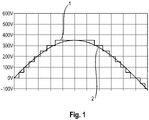
- stepped voltage 1 illustrates the principle of the adjustment or "smoothing" of a stepped voltage 1 that can be generated with a modular battery storage system into a sinusoidal voltage 2 that can be used in particular for feeding into an AC network.
- the stepped voltage is generated in such a way that individual energy storage modules of a modular battery storage system are switched on and off successively, resulting in a total voltage in stepped gradations.
- This step-down voltage 1 approximates a sinusoidal voltage in a power grid.
- PWM pulse width modulation
- the stepped voltage 1 is just one example of the possibilities of a modular battery storage system. In principle, any curve shape can be generated with a circuit of the individual energy storage modules of a modular battery storage system.
- FIG. 2 1 illustrates a conventional modular battery storage system with a plurality of individual energy storage modules 11, each of which is assigned a switch 12.
- the energy storage modules 11 are rechargeable energy storage modules. Exactly one energy storage module 11 is assigned to each of the switches 12 and vice versa.
- the respective energy storage modules 11 can be activated and deactivated by means of the switches 12 .
- Each of the switches 12 can have several switching positions. In a first switching position, the energy storage module 11 assigned to the switch 12 is activated and its individual voltage U single is available. In a second switching position, the energy storage module 11 assigned to the switch 12 is deactivated and its individual voltage U single is not available. If necessary, a third switching position can be provided, in which the energy storage module 11 associated with the switch 12 is activated with reversed polarity.
- All switches 12 are advantageously designed to be able to bypass the energy storage modules 11 associated with them in the event of deactivation.
- deactivated energy storage modules 11 can be exchanged during operation.
- the switches 12 are connected in series.
- the energy storage modules 11 can thus be connected via the switches 12 in such a way that the individual voltages U single of activated energy storage modules 11 add up to form a total voltage U total . If one of the switches 12 is in the second switching position, it bypasses the deactivated energy storage module 11 assigned to it. If one of the switches 12 is in the third switching position, the individual voltage U single of the energy storage module 11 assigned to it makes a negative contribution to the total voltage U total .
- a stepped voltage can be generated from the addition of the individual voltages, which approximates a sinusoidal curve of the voltage.
- the individual voltage generated in the individual energy storage modules 11 is conventionally subjected to a PWM via the respectively associated switch 12 before the modulated individual voltages are added.
- the modular battery storage system 10 has a neutral conductor 16 and an output 17, it being possible for the total voltage, which in particular approximates a sinusoidal voltage, to be fed into a mains voltage via the output conductor 17.
- a high clock frequency is required for the PWM, so that the correspondingly high-frequency control 14 of the individual switches 12 leads to the formation of electromagnetic interference 15 in the area of the individual energy storage modules 11 and also in the area of the lines for control 14 of the switches 12.
- the rapid switching processes at the switches 12 cause strong alternating magnetic fields, which can mean that the modular battery storage system can hardly be used in practice.
- the structure of the modular battery storage system 10 not only interferes with its own operation due to the electromagnetic interference emissions, but can also emit considerable interference to the outside and magnetically couple it into adjacent conductors. This necessitates complex shielding against electromagnetic interference emissions in the entire area of the modular battery storage system 10 .
- the output conductor 17 also causes electromagnetic interference emissions 18 which should be shielded.
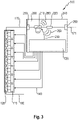
- FIG. 3 illustrates a modular battery storage system 100 according to the invention.
- a plurality of energy storage modules 110 is provided, each of which is assigned a switch 120 .
- the inside 3 indicated neutral conductor 160 is not absolutely necessary.
- the system can also be constructed as a pure three-phase system.
- a comparatively simple circuit 120 is provided here in each case, which primarily allows the individual energy storage modules 110 to be switched on and off and which is driven at a low frequency.
- the corresponding actuation 140 via the control device 130 is therefore slow and can have a frequency of 100 Hz, for example, which corresponds to the cycle of mains half-waves. For example, simple 0/1 signal lines are sufficient here.
- a data bus is not required, or a very simply designed communication bus can be provided. In particular, no real-time capable lines are required. Due to the simple switches 120 and the simple signal lines 140, there is no relevant emission of electromagnetic interference in the area of the individual energy storage modules 110, so that complex shielding measures can be dispensed with in this area.
- the individual voltages U single which are generated in the individual connected or activated energy storage modules 110 , are added to form a total voltage U total and fed into a central modulation unit 200 via the output conductor 170 .
- the core of the modulation unit 200 is a pulse width modulation switch 210, which undertakes the pulse width modulation of the voltage profile required for a fine adjustment of the total voltage U total .
- Downstream of the pulse width modulation switch 210 is a filter inductor 220, which ensures further smoothing of the overall voltage that has been chopped up to a certain extent by the pulse width modulation.
- the clock frequency for the pulse width modulation which takes place through direct control via a control line 230 of the control device 130, is selected to be relatively high, since the filter inductor 220 is then particularly effective and can accordingly be designed to be relatively small. Since the filter choke 220 is generally the most expensive component of the entire battery storage system 100, this measure offers considerable potential for savings.
- the electromagnetic interference emissions 280 arising in connection with the high-frequency pulse width modulation are effectively shielded by a housing 240 of the modulation unit 200, with the housing 240 or the modulation unit 200 having a particularly advantageous particularly compact and robust design.
- a low-pass filter 250, 260 can be provided at the input and at the output of the modulation unit 200 in order to further smooth the total voltage U total .
- the resulting total voltage U total 171 after passing through the modulation unit 200 is particularly suitable for being fed into an AC network, for example as one of three phases, for example.
- the control device 130 is preferably an integral component of the modulation unit 200, since in this way protection and shielding from the outside are also achieved for the control device 130 in a particularly suitable manner.
- the pulse width modulation switch 210 can be controlled directly by the control device 130 via the control 230, with a fast data bus for the control 230 not being absolutely necessary.
- the electromagnetic interference emission 280 caused by the high-frequency controlled pulse width modulation switch 210 is reliably shielded by the housing 240 .
- the compact and concentrated design of the modulation unit 200 which also integrates the filter inductor 220, allows high switching frequencies and thus allows the size and costs of the individual components to be reduced.
- the expansive structure formed by the individual energy storage modules 110 can be formed without further shielding measures, which further reduces costs and simplifies the housing construction in the peripheral area of the battery storage system, so to speak.
- the modulation unit 200 comprises a cooling device that is not illustrated in detail here.
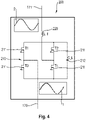
- the pulse width modulation switch 210 comprises an H-bridge circuit with two line branches, each with two semiconductor switches (T1, T2 and T3, T4), which are connected to one another (C_L) via a capacitor (212).
- the total voltage U total from the here not shown energy storage modules via their output conductor 170 fed.
- the total voltage U total has the form of a step voltage 1 in this example.
- the voltage across the capacitor 212 is set or regulated by driving the power semiconductors 211, in particular by pulse width modulation.
- a smoothed sinusoidal voltage profile 2 results, which can be fed into a mains voltage, for example, as one of the three mains phases.
- a sinusoidal shape of the resulting voltage is only one possible example of the voltage that can be generated with the modular battery storage system according to the invention.
- other waveforms or a direct current can also be generated.
Landscapes
- Engineering & Computer Science (AREA)
- Chemical & Material Sciences (AREA)
- Chemical Kinetics & Catalysis (AREA)
- Electrochemistry (AREA)
- General Chemical & Material Sciences (AREA)
- Power Engineering (AREA)
- Manufacturing & Machinery (AREA)
- Transportation (AREA)
- Mechanical Engineering (AREA)
- Microelectronics & Electronic Packaging (AREA)
- Inorganic Chemistry (AREA)
- Life Sciences & Earth Sciences (AREA)
- Sustainable Development (AREA)
- Sustainable Energy (AREA)
- Charge And Discharge Circuits For Batteries Or The Like (AREA)
- Inverter Devices (AREA)
Priority Applications (8)
| Application Number | Priority Date | Filing Date | Title |
|---|---|---|---|
| EP21155140.3A EP4040623A1 (fr) | 2021-02-04 | 2021-02-04 | Système modulaire de stockage par batteries avec modules d'accumulation d'énergie rechargeables et procédés de fonctionnement du système d'accumulateur de batterie |
| PCT/EP2021/086206 WO2022167136A1 (fr) | 2021-02-04 | 2021-12-16 | Système de stockage de batterie modulaire avec modules de stockage d'énergie rechargeables, et procédé de fonctionnement de système de stockage de batterie |
| KR1020237030023A KR20230143162A (ko) | 2021-02-04 | 2021-12-16 | 재충전 가능한 에너지 저장 모듈들을 갖는 모듈식 배터리 저장 시스템 및 배터리 저장 시스템을 동작시키기 위한 방법 |
| CN202180093120.9A CN116848696A (zh) | 2021-02-04 | 2021-12-16 | 具有可重复充电的储能器模块的模块化电池储能器系统以及用于运行电池蓄储能器系统的方法 |
| AU2021426075A AU2021426075A1 (en) | 2021-02-04 | 2021-12-16 | Modular battery storage system with rechargeable energy storage modules, and method for operating the battery storage system |
| JP2023547184A JP2024505297A (ja) | 2021-02-04 | 2021-12-16 | 再充電可能エネルギー貯蔵モジュールを有するモジュラーバッテリー貯蔵システム、及びバッテリー貯蔵システムを動作させる方法 |
| US18/275,441 US20240120741A1 (en) | 2021-02-04 | 2021-12-16 | Modular battery storage system with rechargeable energy storage modules, and method for operating the battery storage system |
| JP2025167193A JP2026009979A (ja) | 2021-02-04 | 2025-10-03 | 再充電可能エネルギー貯蔵モジュールを有するモジュラーバッテリー貯蔵システム、及びバッテリー貯蔵システムを動作させる方法 |
Applications Claiming Priority (1)
| Application Number | Priority Date | Filing Date | Title |
|---|---|---|---|
| EP21155140.3A EP4040623A1 (fr) | 2021-02-04 | 2021-02-04 | Système modulaire de stockage par batteries avec modules d'accumulation d'énergie rechargeables et procédés de fonctionnement du système d'accumulateur de batterie |
Publications (1)
| Publication Number | Publication Date |
|---|---|
| EP4040623A1 true EP4040623A1 (fr) | 2022-08-10 |
Family
ID=74553606
Family Applications (1)
| Application Number | Title | Priority Date | Filing Date |
|---|---|---|---|
| EP21155140.3A Pending EP4040623A1 (fr) | 2021-02-04 | 2021-02-04 | Système modulaire de stockage par batteries avec modules d'accumulation d'énergie rechargeables et procédés de fonctionnement du système d'accumulateur de batterie |
Country Status (7)
| Country | Link |
|---|---|
| US (1) | US20240120741A1 (fr) |
| EP (1) | EP4040623A1 (fr) |
| JP (2) | JP2024505297A (fr) |
| KR (1) | KR20230143162A (fr) |
| CN (1) | CN116848696A (fr) |
| AU (1) | AU2021426075A1 (fr) |
| WO (1) | WO2022167136A1 (fr) |
Cited By (1)
| Publication number | Priority date | Publication date | Assignee | Title |
|---|---|---|---|---|
| DE102024114152A1 (de) * | 2024-05-21 | 2025-11-27 | PULSETRAIN GmbH | Verfahren zum Pulsentladen |
Families Citing this family (2)
| Publication number | Priority date | Publication date | Assignee | Title |
|---|---|---|---|---|
| WO2025231058A1 (fr) * | 2024-04-30 | 2025-11-06 | RJ1 Holdings Inc. | Systèmes et procédés de surveillance et de commande d'élément unique |
| CN119291544B (zh) * | 2024-10-22 | 2025-12-16 | 广东电网有限责任公司 | 一种储电设备的健康状态监测系统和方法 |
Citations (6)
| Publication number | Priority date | Publication date | Assignee | Title |
|---|---|---|---|---|
| DE102010041059A1 (de) * | 2010-09-20 | 2012-03-22 | Robert Bosch Gmbh | Verfahren zum Einstellen einer Soll-Ausgangsspannung eines Energieversorgungszweiges eines steuerbaren Energiespeichers |
| DE102010064311A1 (de) * | 2010-12-29 | 2012-07-05 | Robert Bosch Gmbh | Steuerbarer Energiespeicher und Verfahren zum Betreiben eines steuerbaren Energiespeichers |
| CN203825198U (zh) * | 2014-04-24 | 2014-09-10 | 东南大学 | 一种高精度动态卫星导航设备检测车 |
| US20140370348A1 (en) * | 2011-12-19 | 2014-12-18 | Robert Bosch Gmbh | Electrical energy storage module and method for producing an electrical energy storage module |
| JP5736194B2 (ja) * | 2011-02-28 | 2015-06-17 | 本田技研工業株式会社 | 車両の電装系ユニット配置構造 |
| WO2018162122A1 (fr) | 2017-03-10 | 2018-09-13 | Varta Microbattery Gmbh | Procédé de fonctionnement d'un système de stockage de batterie modulaire, système de stockage de batterie modulaire et système de gestion de batterie correspondant |
Family Cites Families (13)
| Publication number | Priority date | Publication date | Assignee | Title |
|---|---|---|---|---|
| US5514916A (en) * | 1993-03-22 | 1996-05-07 | Yang; Tai-Her | Power unit with controlled sparking |
| JPH1189242A (ja) * | 1997-09-08 | 1999-03-30 | Yaskawa Electric Corp | 電力変換装置 |
| JP4383981B2 (ja) * | 2004-08-04 | 2009-12-16 | トヨタ自動車株式会社 | インバータ装置 |
| JP2007098981A (ja) * | 2005-09-30 | 2007-04-19 | Toyota Motor Corp | 車両用電源装置 |
| JP5734672B2 (ja) * | 2011-01-12 | 2015-06-17 | 株式会社東芝 | 半導体電力変換装置 |
| JP2012172611A (ja) * | 2011-02-22 | 2012-09-10 | Mitsubishi Heavy Ind Ltd | インバータ一体型電動圧縮機 |
| AU2012297567C1 (en) * | 2011-08-12 | 2026-03-19 | Kevin Stephen Davies | Power conversion system |
| DE102012205119A1 (de) * | 2012-03-29 | 2013-10-02 | Robert Bosch Gmbh | Verfahren zum Aufheizen von Energiespeicherzellen einer Energiespeichereinrichtung und aufheizbare Energiespeichereinrichtung |
| JP6139111B2 (ja) * | 2012-11-15 | 2017-05-31 | 株式会社東芝 | 無効電力補償装置 |
| JP5960079B2 (ja) * | 2013-03-11 | 2016-08-02 | 日立オートモティブシステムズ株式会社 | 電力変換装置 |
| JP6326618B2 (ja) * | 2014-01-31 | 2018-05-23 | パナソニックIpマネジメント株式会社 | 電力変換装置 |
| SE539911C2 (en) * | 2015-11-18 | 2018-01-09 | Optistring Tech Ab | Common line communication in cascaded inverters |
| US10431989B2 (en) * | 2016-01-14 | 2019-10-01 | Jabil Inc. | Low voltage, low frequency, multi level power converter |
-
2021
- 2021-02-04 EP EP21155140.3A patent/EP4040623A1/fr active Pending
- 2021-12-16 CN CN202180093120.9A patent/CN116848696A/zh active Pending
- 2021-12-16 US US18/275,441 patent/US20240120741A1/en active Pending
- 2021-12-16 KR KR1020237030023A patent/KR20230143162A/ko active Pending
- 2021-12-16 JP JP2023547184A patent/JP2024505297A/ja active Pending
- 2021-12-16 WO PCT/EP2021/086206 patent/WO2022167136A1/fr not_active Ceased
- 2021-12-16 AU AU2021426075A patent/AU2021426075A1/en active Pending
-
2025
- 2025-10-03 JP JP2025167193A patent/JP2026009979A/ja active Pending
Patent Citations (6)
| Publication number | Priority date | Publication date | Assignee | Title |
|---|---|---|---|---|
| DE102010041059A1 (de) * | 2010-09-20 | 2012-03-22 | Robert Bosch Gmbh | Verfahren zum Einstellen einer Soll-Ausgangsspannung eines Energieversorgungszweiges eines steuerbaren Energiespeichers |
| DE102010064311A1 (de) * | 2010-12-29 | 2012-07-05 | Robert Bosch Gmbh | Steuerbarer Energiespeicher und Verfahren zum Betreiben eines steuerbaren Energiespeichers |
| JP5736194B2 (ja) * | 2011-02-28 | 2015-06-17 | 本田技研工業株式会社 | 車両の電装系ユニット配置構造 |
| US20140370348A1 (en) * | 2011-12-19 | 2014-12-18 | Robert Bosch Gmbh | Electrical energy storage module and method for producing an electrical energy storage module |
| CN203825198U (zh) * | 2014-04-24 | 2014-09-10 | 东南大学 | 一种高精度动态卫星导航设备检测车 |
| WO2018162122A1 (fr) | 2017-03-10 | 2018-09-13 | Varta Microbattery Gmbh | Procédé de fonctionnement d'un système de stockage de batterie modulaire, système de stockage de batterie modulaire et système de gestion de batterie correspondant |
Cited By (2)
| Publication number | Priority date | Publication date | Assignee | Title |
|---|---|---|---|---|
| DE102024114152A1 (de) * | 2024-05-21 | 2025-11-27 | PULSETRAIN GmbH | Verfahren zum Pulsentladen |
| DE102024114152B4 (de) * | 2024-05-21 | 2025-12-31 | PULSETRAIN GmbH | Verfahren zum Pulsentladen |
Also Published As
| Publication number | Publication date |
|---|---|
| AU2021426075A9 (en) | 2024-09-26 |
| JP2024505297A (ja) | 2024-02-05 |
| JP2026009979A (ja) | 2026-01-21 |
| CN116848696A (zh) | 2023-10-03 |
| WO2022167136A1 (fr) | 2022-08-11 |
| KR20230143162A (ko) | 2023-10-11 |
| AU2021426075A1 (en) | 2023-08-03 |
| US20240120741A1 (en) | 2024-04-11 |
Similar Documents
| Publication | Publication Date | Title |
|---|---|---|
| EP3286033B1 (fr) | Circuit de puissance pour l'alimentation électrique dans un véhicule à propulsion électrique et système d'alimentation en énergie fixe | |
| EP2067230B1 (fr) | Dispositif destiné à l'alimentation en énergie électrique d'un réseau d'alimentation en énergie et convertisseur pour un tel dispositif | |
| DE102012200841B4 (de) | Elektrisches system und verfahren | |
| DE102018106305B4 (de) | Wechselstromladung einer intelligenten Batterie | |
| EP3245727B1 (fr) | Module convertisseur pour convertisseur d'énergie multiniveaux | |
| DE112017003632T5 (de) | Dc/dc-umrichter | |
| DE102019106485B4 (de) | Weissach-Gleichrichteranordnung | |
| DE102010031615A1 (de) | Ladevorrichtung mit galvanischer Trennung und vielfältigen Betriebsarten | |
| WO2022167136A1 (fr) | Système de stockage de batterie modulaire avec modules de stockage d'énergie rechargeables, et procédé de fonctionnement de système de stockage de batterie | |
| EP2299572A1 (fr) | Démarrage d'un convertisseur CC/CC avec un transformateur à haute fréquence | |
| DE102010038880A1 (de) | Energiewandler zum Ausgeben elektrischer Energie | |
| DE102018008603A1 (de) | Schaltungsanordnung und Verfahren zum Laden einer Batterieanordnung mit mehreren Batteriemodulen | |
| DE202021100557U1 (de) | Modulares Batteriespeichersystem mit wiederaufladbaren Energiespeichermodulen | |
| DE4426017C2 (de) | Stromversorgungsgerät, insbesondere Batterie-Ladegerät für Elektrofahrzeuge oder dergleichen | |
| DE102011005911A1 (de) | Ladeeinrichtung für eine Hochspannungsbatterie | |
| EP3257145A1 (fr) | Convertisseur cc/cc avec condensateur flottant | |
| DE102012220371A1 (de) | Vorrichtung zum Laden eines elektrischen Energiespeichers aus einer Wechselspannungsquelle | |
| EP2826126B1 (fr) | Dispositif électronique de puissance comportant une symétrisation d'un n ud de tension dans le circuit intermédiaire | |
| WO2025168323A1 (fr) | Convertisseur de puissance à redresseur actif et convertisseur à compensation de mode commun dans la liaison cc | |
| DE102012206801A1 (de) | Schaltung mit einer stromrichterschaltung und verfahren zur leistungsanpassung | |
| DE102020109426A1 (de) | Ladevorrichtung zum Laden eines elektrischen Energiespeichers eines elektrisch betriebenen Fahrzeugs mit einem Gleichspannungswandler | |
| DE102020111355A1 (de) | Ladevorrichtung und Verfahren zum Laden eines elektrischen Energiespeichers eines elektrisch betriebenen Fahrzeugs mittels eines Gleichspannungswandlers, welcher verschiedene Betriebsmodi aufweist | |
| DE102010042718A1 (de) | Verfahren zur Steuerung einer Batterie mit variabler Ausgangsspannung | |
| DE102011083645A1 (de) | Batterie-Ladegerät | |
| DE102020115444A1 (de) | Verfahren zum Betreiben einer elektrischen Verbrauchereinrichtung in einem Energieversorgungsnetz eines Haushalts und/oder einer Industrieanlage, sowie Energieversorgungsnetz und Energiespeichervorrichtung für ein solches Energieversorgungsnetz |
Legal Events
| Date | Code | Title | Description |
|---|---|---|---|
| PUAI | Public reference made under article 153(3) epc to a published international application that has entered the european phase |
Free format text: ORIGINAL CODE: 0009012 |
|
| STAA | Information on the status of an ep patent application or granted ep patent |
Free format text: STATUS: THE APPLICATION HAS BEEN PUBLISHED |
|
| AK | Designated contracting states |
Kind code of ref document: A1 Designated state(s): AL AT BE BG CH CY CZ DE DK EE ES FI FR GB GR HR HU IE IS IT LI LT LU LV MC MK MT NL NO PL PT RO RS SE SI SK SM TR |
|
| STAA | Information on the status of an ep patent application or granted ep patent |
Free format text: STATUS: REQUEST FOR EXAMINATION WAS MADE |
|
| 17P | Request for examination filed |
Effective date: 20230210 |
|
| RBV | Designated contracting states (corrected) |
Designated state(s): AL AT BE BG CH CY CZ DE DK EE ES FI FR GB GR HR HU IE IS IT LI LT LU LV MC MK MT NL NO PL PT RO RS SE SI SK SM TR |