EP4040937B1 - Dispositif de travail d'un sol agricole - Google Patents
Dispositif de travail d'un sol agricole Download PDFInfo
- Publication number
- EP4040937B1 EP4040937B1 EP21807095.1A EP21807095A EP4040937B1 EP 4040937 B1 EP4040937 B1 EP 4040937B1 EP 21807095 A EP21807095 A EP 21807095A EP 4040937 B1 EP4040937 B1 EP 4040937B1
- Authority
- EP
- European Patent Office
- Prior art keywords
- clamping
- articulation
- lever
- operating member
- carrier elements
- Prior art date
- Legal status (The legal status is an assumption and is not a legal conclusion. Google has not performed a legal analysis and makes no representation as to the accuracy of the status listed.)
- Active
Links
Images








Classifications
-
- A—HUMAN NECESSITIES
- A01—AGRICULTURE; FORESTRY; ANIMAL HUSBANDRY; HUNTING; TRAPPING; FISHING
- A01B—SOIL WORKING IN AGRICULTURE OR FORESTRY; PARTS, DETAILS, OR ACCESSORIES OF AGRICULTURAL MACHINES OR IMPLEMENTS, IN GENERAL
- A01B63/00—Lifting or adjusting devices or arrangements for agricultural machines or implements
- A01B63/14—Lifting or adjusting devices or arrangements for agricultural machines or implements for implements drawn by animals or tractors
- A01B63/24—Tools or tool-holders adjustable relatively to the frame
- A01B63/245—Tools or tool-holders adjustable relatively to the frame laterally adjustable
-
- A—HUMAN NECESSITIES
- A01—AGRICULTURE; FORESTRY; ANIMAL HUSBANDRY; HUNTING; TRAPPING; FISHING
- A01B—SOIL WORKING IN AGRICULTURE OR FORESTRY; PARTS, DETAILS, OR ACCESSORIES OF AGRICULTURAL MACHINES OR IMPLEMENTS, IN GENERAL
- A01B63/00—Lifting or adjusting devices or arrangements for agricultural machines or implements
- A01B63/14—Lifting or adjusting devices or arrangements for agricultural machines or implements for implements drawn by animals or tractors
- A01B63/24—Tools or tool-holders adjustable relatively to the frame
- A01B63/26—Tools or tool-holders adjustable relatively to the frame by man-power
-
- A—HUMAN NECESSITIES
- A01—AGRICULTURE; FORESTRY; ANIMAL HUSBANDRY; HUNTING; TRAPPING; FISHING
- A01B—SOIL WORKING IN AGRICULTURE OR FORESTRY; PARTS, DETAILS, OR ACCESSORIES OF AGRICULTURAL MACHINES OR IMPLEMENTS, IN GENERAL
- A01B13/00—Ploughs or like machines for special purposes
- A01B13/04—Ploughs or like machines for special purposes for working in vineyards, orchards, or the like
Definitions
- the present invention relates to a device for working an agricultural soil.
- working tools for working the soil between adjacent rows of agricultural crops are moved with the aid of a towing vehicle.
- the working tools can be, for example, chopping tools, rakes, tines, finger stars or the like.
- the distance between rows of agricultural crops is chosen to be different, in particular depending on the type of crop.
- the soil between adjacent rows of crops is regularly tilled by means of agricultural implement units, each of which has a plurality of implements.
- the working device units each with several working tools, are pulled along between adjacent rows of useful plants with the aid of a towing vehicle.
- Agricultural implement units are already known in which it is possible to adjust the implements in the aforementioned manner.
- each individual implement can be separately and be adjusted transversely to the pulling direction independently of another working implement of the same working implement unit. This adjustment is made either by hand by loosening and re-tightening locking screws or the like, or with the help of, for example, electric actuators, each of which adjusts one of the working tools of the working device unit.
- a device for working an agricultural soil by moving the device along the soil in a direction of travel of a towing vehicle for towing the device.
- the device has a device body with a longitudinal plane which is essentially vertical or perpendicular to the soil to be worked and essentially parallel to the direction of travel and the crop rows.
- the device also has a number of working tools and a number of elongate carrier elements which carry the working tools and are adjustably mounted on the device body.
- the carrier elements can each be moved transversely to the longitudinal plane, so that the respective working tool can be arranged at different distances from the longitudinal plane of the device.
- the device according to the invention is provided with a locking device for locking the carrier elements on the device body.
- the carrier elements can be locked or fixed immovably on the device body.
- the locking device comprises an actuating member, which can be actuated to either jointly release an already effective locking of the multiple carrier elements on the device body or to actuate the multiple carrier elements that have not yet been locked can be fixed together to the device body.
- An advantage of the device according to the invention is that the adjustable working tools of the device can be released from their locking jointly in a quick and simple manner by actuating an actuating element or locked together on the device body by actuating an actuating element. Separate handles for releasing or locking individual working tools of the device are thus unnecessary.
- an actuating element for jointly releasing the locking of the plurality of carrier elements and a further actuating element for jointly fixing the plurality of carrier elements could be brought into its locking position against the action of one or more spring elements for jointly fixing the carrier elements. In this locking position, the further actuating element could be held in a form-fitting manner, for example with the aid of a locking element.
- the actuating member for jointly releasing the lock could then act on the locking element when it is actuated in such a way that the bolt releases the further actuating member held in a form-fitting manner and this is pushed back into its release position by the spring element or spring elements.
- the several carrier elements are locked on the device body in a frictional or non-positive manner.
- This enables stepless adjustment of the working tools relative to the longitudinal plane of the device body. Since when editing the agricultural soil, the forces acting transversely to the direction of travel of the towing vehicle or transversely to the longitudinal plane of the device body are significantly lower than the forces acting in the direction of travel or in the direction of the longitudinal plane, a frictional locking of the carrier elements on the device body is perfect within the scope of the present invention sufficient.
- the agricultural working tools can be, for example, hoeing tools.
- Working tools in the form of rakes, tines, finger stars or the like are also conceivable.
- the device body preferably has a plurality of guide receptacles, each with associated guide surfaces. At least one of the carrier elements for carrying a respective work tool is guided displaceably along the respective guide surface in the guide receptacles.
- the locking device acts in a frictional or non-positive manner and has a number of clamping levers for this purpose. At least one of the multiple clamping levers is functionally assigned to each of the multiple guide receptacles for receiving the carrier elements.
- the respective clamping lever can be moved from a clamping position, in which it holds the respective carrier element or the respective carrier elements, by actuating the actuating element which acts jointly on all clamping levers presses against the respective guide surface of the respective guide receptacle and thereby frictionally fixes it or she in the respective guide receptacle in a non-displaceable manner, into a release position in which it releases the respective carrier element or the respective carrier elements, so that it or she is in the respective guide receptacle along the respective guide surface is or are displaceable, and/or vice versa movable.
- the guide receptacles are each formed by a tubular guide sleeve which has at least one through hole through which the respective clamping lever or clamping levers can reach to fix the respective carrier element. It is sufficient for the clamping lever or levers to be able to act on the carrier element only with the length range required for clamping through the through-hole.
- the plurality of clamping levers are preferably mounted on the device body such that they can rotate about a respective axis of rotation.
- the locking device advantageously comprises at least one connecting rod, with each of the several clamping levers being articulated to the connecting rod via a respective joint in such a way that a longitudinal section of the respective clamping lever lying between the respective axis of rotation and the respective joint is directly or can act indirectly on the respective carrier element and thus serves to set the respective carrier element.
- An indirect attack of a clamping lever on a carrier element can be considered, for example, if two carrier elements are mounted in a guide receptacle and the clamping lever presses directly against only one of the carrier elements. against the other of the two in the same In this case, the clamping lever presses the support elements guided adjacent to the guide receptacle only indirectly. The clamping force applied by the clamping lever to the carrier element directly touched by it is conveyed to the other carrier element via the directly touched carrier element.
- the locking device preferably also comprises a number of damping devices which are each arranged to act between the connecting rod and the respective clamping lever.
- the damping devices advantageously allow for the compensation of tolerances and other dimensional inaccuracies relating to the individual components of the locking device.
- the respective damping device preferably has a support rod and a compression spring.
- the respective support rod is connected in an articulated manner to the connecting rod at the respective joint. Furthermore, the respective support rod passes through the respective clamping lever in such a way that it can move relative to the respective clamping lever.
- the respective compression spring is supported on the one hand on the support rod and on the other hand on the respective clamping lever.
- the actuator is preferably a cam member having a cam control surface and mounted on the device body for rotation about a cam axis.
- the actuation of the cam element can take place, for example, with the aid of a conventional wrench or the like.
- the locking device can advantageously comprise an adjusting lever which is mounted on the device body such that it can rotate about an adjusting lever axis.
- the adjusting lever In a region of the adjusting lever located on one side of the adjusting lever axis, the adjusting lever has a contact surface on which the cam control surface can engage in order to cause the adjusting lever to rotate about its adjusting lever axis.
- the locking device of the device comprises at least one compensating member which is articulated to the connecting rod via a first compensating joint and articulated to the adjusting lever via a second compensating joint on a side of the adjusting lever axis remote from the working surface.
- the compensating member serves to compensate for movement components of the connecting rod in the vertical direction, which result from the rotary movements of the clamping levers about their respective axis of rotation on the device body.
- the first compensating joint preferably coincides with that joint which articulates the connecting rod with that clamping lever which is arranged lying closest to the adjusting lever. This is advantageous because in this way a separate compensating joint for articulating the compensating member on the connecting rod is saved and the installation space of the locking device can thus be kept small.
- a lever-like actuating element can alternatively be provided, which is operatively connected to a first and a second clamping lever.
- the operative connection consists in the fact that those ends of the first and second clamping levers that face away from the carrier elements are pulled towards one another in the respective clamping position, so that the carrier elements assigned to the first and second clamping levers are pressed away from one another in the clamping position against guide surfaces of the guide receptacles become.
- the pulling of the aforementioned ends toward one another and the aforementioned pushing away of the carrier elements occur when the clamping levers are mounted on the device body via pivots. If this is not the case, the two clamping levers and the two carrier elements are pulled toward one another.
- the actuating member can be connected in an articulated manner to the first clamping lever via a swivel joint.
- An elongate pulling element can be connected to the actuating member via a first joint and to the second clamping lever via a second joint.
- the first joint and the pivot joint are spaced apart from one another, this distance representing the maximum effective lever arm between the first joint and the pivot joint.
- the lever-like actuating element When the lever-like actuating element is pivoted or rotated about the axis of the pivot joint from a release position, in which the clamping levers are in their release position, to a locking position, in which the clamping levers are in their clamping position, the first joint moves away from the second joint against the action of an elastic restoring force. This increase continues until a maximum value of the distance is reached in a dead center position of the actuating member. The distance between the first joint and the second joint then decreases again due to the effect of the elastic restoring force.
- the release position of the lever-like actuating member is on one side of the dead center of the pivoting path of the actuating member, while the locking position is on the other side of the dead center of the pivoting path of the actuating member. It is thereby effectively avoided that the actuating member can move by itself from the locked position to the release position or vice versa.
- the first joint which connects the actuating member to the pulling element, preferably has a joint element through which the pulling element passes in such a way that it can be moved in a longitudinal direction relative to the pulling element.
- the joint element can be, for example, a joint sleeve through which the tension element passes transversely.
- the elastic restoring force can be brought about by at least one compression spring, which is supported on the tension element and presses the joint element in the direction of the second joint, which connects the tension element to the second clamping lever.
- the actuating member is supported on the first or the second clamping lever and then pulls the other clamping lever when the actuating member is pivoted from the release position into the locking position.
- This variant requires few individual parts and is therefore advantageous both in terms of cost and weight.
- the actuating member is mounted in an articulated manner on the device body in an intermediate space between the first and the second clamping lever via a swivel joint.
- the actuating element is supported on the device body.
- Each of the clamping levers is connected in an articulated manner to the actuating member via its own tension element.
- the ends of the tension elements facing away from the actuating member are also connected in an articulated manner to the respectively associated clamping element.
- the actuating element is pivoted from the release position into the locking position, the same movement and force conditions result as in the preceding variant.
- the clamping levers are mounted on the device body via pivots, their ends, on which the respective pulling element is articulated, are drawn towards one another.
- the carrier elements which pass through the respectively associated guide receptacle and the clamping hole of the respectively associated clamping lever, are pressed away from one another against guide surfaces of the guide receptacle and are thus clamped.
- both the clamping levers and the carrier elements are drawn towards one another, so that the carrier elements are clamped in this way in the guide receptacle.
- the actuating member can be mounted in an articulated manner on the device body via a pivot joint outside of an intermediate space between the first and the second clamping lever.
- a first pulling element is articulated to the actuating member on the one hand and articulated to the first clamping lever on the other hand.
- the clamping levers are connected to one another via a second tension element, the second tension element being articulated to the first clamping lever and articulated to the second clamping lever.
- the actuating element is pivoted from the release position into the locking position, the ends of the clamping levers connected to the tie rods are pulled in the same direction. If the clamping levers are each mounted with an axis of rotation on the device body, the carrier elements are in turn pressed in the same direction, which, however, is directed opposite to the direction in which the ends of the clamping levers facing away from the carrier elements are pulled. If the clamping levers are not mounted on the device body by means of pivots, the clamping levers and the carrier elements are all pulled in the same direction towards the actuating member.
- a particularly simple construction can advantageously be achieved in that the clamping levers are arranged in such a way that they are located outside of the guide receptacle and act on the carrier elements outside of the device body. It is then not necessary to provide sufficient space for the clamping levers within the device body.
- each of the clamping levers can be configured as a double lever. This double lever can then act on the respective carrier element on two opposite sides of the device body. The clamping forces then act symmetrically on the carrier elements with regard to the guide receptacles in the device body.
- the clamping levers can each have a clamping hole passing through them, through which the respective carrier element extends.
- the hole walls of the clamping hole can then encompass the respective carrier element on at least three sides. It is preferable to provide a clamping hole that is completely circumferentially delimited by hole walls and whose hole walls encompass the respective carrier hole on all sides.
- the respective clamping hole preferably has a first, non-round shape and the cross section of the respective carrier element has a second, non-round shape.
- the first, non-round shape and the second, non-round shape are particularly preferably designed identically, for example as a polygonal shape, in particular a square shape or hexagonal shape, or other non-round shape. Basically, there must be sufficient play between the hole walls of the respective clamping hole and the surface of the respective carrier element so that the latter can be moved without any problems when the clamping lever is in the release position.
- the clamping levers can be mounted on the device body such that they can rotate about respective axes of rotation, but they do not have to be, at least when the respective clamping hole has a first, non-round shape and the cross section of the respective carrier element has a second, non-round shape. If the clamping levers are not mounted on the device body, they will together with the tension element and the actuating element are held by the carrier elements, which in turn are seated in the guide receptacles of the device body. If the support elements are pulled out of the guide receptacles in this design, they no longer pass through the clamping hole in the respective clamping lever. The unit comprising the clamping levers, the pulling element and the actuating member then hangs freely in the air and must be held in place before the support elements are pulled out of the clamping holes if it is to be prevented from falling.
- any axes of rotation of the clamping levers that may be present can each be mounted in a slot on the device body.
- the axes of rotation can then move in a limited translational manner in accordance with the length of the elongated hole guided in the latter. This has the advantage that manufacturing tolerances can be compensated for without any problems.
- In 1 three devices 1 according to the invention and designed in the same way for processing an agricultural soil can be seen in the view from above. Between the in 1 middle device 1 and the in 1 left device 1 and between the in 1 middle device 1 and the in 1 device 1 on the right shows a row of useful plants NR.
- the three devices 1 are pulled together with the aid of a towing vehicle (not shown) over the agricultural soil in a direction of travel FR. In practice, a towing vehicle pulls even more than the three devices 1 shown over the ground BD.
- each of the three devices 1 has a total of four working tools 3, 4, 5 and 6 in the form of chopping tools.
- the working tools 3, 4, 5 and 6 With the help of the working tools 3, 4, 5 and 6, the agricultural soil BD between adjacent crop rows NR is to be evenly chopped.
- the working tools 3, 4, 5 and 6 are distributed evenly over the working width BB defined by the distance between the crop rows NR.
- the existing processing widths BB vary in size depending, among other things, on the type of specific useful plant.
- In 1 are the working tools 3, 4, 5 and 6 for processing a shown, first Processing width BB arranged. If a second machining width BB, which is smaller than the first machining width BB, is to be machined with the same device 1, it is necessary to increase the distances between the working tools 3, 4, 5 and 6 by one in 1 to change or adjust the longitudinal plane LE of a device body 2 of the device 1 drawn in by way of example on the far left with a dot-dash line.
- the working tools 3, 4, 5 and 6 are fastened to elongate support elements 7, 8, 9 and 10, which in turn are arranged in an in 1 are supported on the device body 2 so as to be displaceable to the left or right in the horizontal direction.
- the locking of the carrier elements 7, 8, 9 and 10 on the device body 2 is first released together. Then the carrier elements 7, 8, 9 and 10 in 1 is shifted or adjusted in the horizontal direction to the right or left until a uniform arrangement of the working tools 3, 4, 5 and 6 is achieved over the changed processing width BB. Subsequently, the carrier elements 7, 8, 9 and 10 are all locked again together, so that the device 1 is then ready for processing the soil BD with a changed processing width BB.
- the device body 2 here comprises two body plates which are arranged parallel to one another and are spaced apart from one another.
- the carrier elements 7, 8, 9 and 10 are slidably mounted on these two body plates.
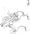
- In 3 is a side view of the in 2
- the device 1 shown is shown obliquely from below, with the working tools 3, 4, 5 and 6 and one of the two body plates of the device body 2 being omitted in order to better visualize the construction between the two body plates make.
- the device body 2 has three guide receptacles 12, 13 and 14 in the form of relatively short, tubular square sleeves.
- the carrier element 7 is pushed into the guide receptacle 12 .
- the carrier element 8 is pushed into the guide receptacle 13 .
- the two carrier elements 9 and 10 are pushed into the guide receptacle 14 .
- the carrier elements 7, 8, 9 and 10 also have a square cross-section, so that a rotational movement of the carrier elements 7, 8, 9 and 10 within the guide receptacles 12, 13 and 14 about their respective longitudinal axis is positively prevented .
- other cross-sectional geometries or other structural means can also be used in order to fix the carrier elements 7, 8, 9 and 10 in a rotationally fixed manner in the guide receptacles 12, 13 and 14.
- the locking device for releasing and locking the carrier elements 7, 8, 9 and 10 in the guide receptacles 12, 13 and 14 comprises a total of four clamping levers 18, 19, 20 and 21, each of which can be pivoted about an axis of rotation 23, 24 and 25 are mounted on the device body 2.
- the clamping lever 18 is functionally associated with the carrier element 7 and the clamping lever 19 is functionally associated with the carrier element 8 .
- the two in 3 To be seen clamping levers 20 and 21 are functionally assigned to the carrier elements 9 and 10 together.
- the locking device further comprises a connecting rod 26 for connecting the clamping levers 18, 19, 20 and 21 to one another.
- the connecting rod 26 is formed by two pieces of flat material which run parallel to one another and are spaced apart from one another.
- the clamping lever 18 is connected via a joint 27, and the clamping lever 19 is connected via a joint 28 to the connecting rod 26.
- the two clamping levers 20 and 21 are connected to the connecting rod 26 via a joint joint 29 .
- an adjusting lever 45 can be seen on the right, which is mounted on the device body 2 so as to be rotatable about an adjusting lever axis 46 in its middle region.
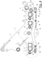
- the adjusting lever axis 46 divides the adjusting lever 45 into an in 4 upper arm and an in 4 lower arm. the inside 4
- the upper arm has an engaging surface 47 which, in the embodiment shown, is intended to be engaged by a cam control surface 43 of an actuator 11 in the form of a cam member.
- the actuating member 11 in the form of the cam element is around the in 4 marked cam axis 44 rotatable.
- a compensating member 48 is articulated via a compensating joint 50 on the lower arm of the actuating lever 45 .
- the left end of the compensating member 48 is connected to the connecting rod 26 via a compensating joint 49 .
- the joint 27 for the articulated connection of the clamping lever 18 with the connecting rod 26 coincides with the compensating joint 49 in a particularly advantageous manner.
- the compensating member 48 also consists of two pieces of flat material which run parallel to one another and are spaced apart from one another.
- damping devices 30, 31, 32 and 33 can be seen, by means of which the clamping levers 18, 19, 20 and 21 are each connected to the connecting rod 26.
- the damping device 30 connects the clamping lever 18 to the connecting rod 26.
- the damping device 31 connects the clamping lever 19 to the connecting rod 26.
- the damping device 32 connects the clamping lever 20 to the connecting rod 26.
- the damping device 33 connects the clamping lever 21 to the connecting rod 26.
- the damping devices 30, 31, 32 and 33 each have - as in 3 can be seen - a support rod 34, 35, 36 and 37 on.
- the support rod 34 is connected to the connecting rod 26 via the joint 27 .
- the support rod 35 is connected to the connecting rod 26 via the joint 28 .
- the support rods 36 and 37 are connected to the connecting rod 26 via the common joint 29 .
- the damping devices 30, 31, 32 and 33 each have a compression spring 38, 39, 40 and 41 which is supported on the respective support rod 34, 35, 36 and 37.
- the support rods 34, 35, 36 and 37 have a thread at their ends facing away from the joints 27, 28 and 29, with the help of which a disk-shaped spring seat is held by a nut on the respective support rod 34, 35, 36 and 37 becomes.
- FIG. 8 is a perspective view of the embodiment of the device 1 according to the invention shown obliquely from below, wherein the working tools 3, 4, 5 and 6 have been omitted.
- the clamping levers 20 and 21 which act on the carrier elements 9 and 10 can be seen in the detail B.
- the clamping lever 19 which acts on the carrier element 8 can be seen in the detail A.
- 9 shows detail B 8 in an enlarged view.
- the damping devices 32 and 33 assigned to them can be seen.
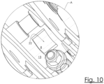
- FIG. 10 shows detail A 8 in an enlarged view, with the clamping lever 19 omitted in order to be able to show a through hole 22 in the guide receptacle 13.
- a through hole 22 which is essentially rectangular here, in 10 to recognize the carrier element 8, which is slidably guided in the guide receptacle 13.
- the clamping lever 19 can act on the carrier element 8 through the through-hole 22 and clamp it in the guide receptacle 13 in a frictionally or non-positive manner.
- a through hole corresponding to the through hole 22 is also provided in the guide seat 12 .
- the clamping lever 18 can reach through it.
- a common through hole or two separate through holes corresponding to the through hole 22 are also arranged in the guide seat 14 .
- the clamping levers 20 and 21 can pass through the common through-hole or the two separate through-holes.
- figure 5 shows detail C 4 in an enlarged view.
- a longitudinal section LA of the clamping lever 20 extends through an in figure 5 through hole located in the lower left area of the guide receptacle 14, but does not attack the lower left corner of the cross section of the carrier element 10.
- a narrow air gap between the longitudinal section LA of the clamping lever 20 and the carrier element 10 can be seen.
- Corresponding conditions are given in an analogous manner in the case of the clamping levers 18 and 19 and the carrier elements 7 and 8 when the clamping levers 18 and 19 are in their release position.
- the carrier elements 7, 8, 9 and 10 can be placed in the guide receptacles 12, 13 and 14 can be locked.
- the actuating element 11 designed as a cam element is 4 rotated around the cam axis 44 by almost 180° clockwise according to arrow P. This can be done, for example, using a conventional wrench 51, as shown in FIGS 2 and 3 is shown.
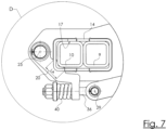
- the clamping force presses the carrier element 10 directly and the carrier element 9 indirectly against guide surfaces 17 which are formed by the inner walls of the guide receptacle 14 .
- the Carrier elements 10 and 9 are frictionally or non-positively fixed or locked in the guide receptacle 14 .
- a movement of the carrier elements 10 and 9 in a direction perpendicular to the longitudinal plane LE of the device body 2 is now no longer possible.
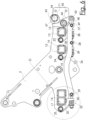
- the example in 7 The conditions shown for the clamping lever 20 and the carrier element 10 are in FIG 6 shown clamping position of the locking device given in an analogous manner with the clamping levers 18 and 19.
- the clamping lever 18 presses the carrier element 7 against guide surfaces 15 which are formed by the inner walls of the guide receptacle 12 .
- the clamping lever 19 presses the carrier element 8 against guide surfaces 16 which are formed by the inner walls of the guide receptacle 13 .
- the actuating element 11 which is designed as a cam element, is released from its in 6 locking position shown back into its release position according to 4 rotated, the clamping levers 18, 19, 20 and 21 move back into their respective release positions due to the force of gravity.
- the contour of the longitudinal section LA of the clamping lever 20 is adapted to the contour of that area of the cross-sectional shape of the carrier element 20 with which the longitudinal section LA interacts when the clamping lever 20 is in the clamping position.
- a single actuating member 11 is provided in a particularly advantageous manner, with the aid of which the plurality of support elements 7, 8, 9 and 10 can be both locked together and released together from the locked state.
- the plurality of support elements 7, 8, 9 and 10 can be both locked together and released together from the locked state.
- more or less than four adjustable support elements can also be mounted on the device body 2. According to the invention, it is only essential that several adjustable carrier elements are present, ie at least two carrier elements.
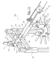
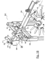
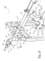
- FIG. 11 shows the perspective view of a second embodiment in the form of the device 101 according to the invention. It has a device body 102 designed as a square profile, on whose in 11 Exactly two carrier elements 107, 108 are attached to the left end, which are also square profiles. Like the carrier elements 7, 8, 9, 10 of the first exemplary embodiment, the carrier elements 107, 108 also extend through guide receptacles which are formed in the device body 102 and have respective guide surfaces which Figures 11 to 15 are not visible.
- the guide receptacle for the carrier element 107 or 108 is a square hole which fixes the device body 102 at its in 11 left end penetrated in such a way that the elongate support element 107 or 108 can be inserted into the guide receptacle in such a way that it is on opposite sides of the device body 102 as in FIG 11 shown looking out.
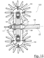
- a synopsis of the 11 and 15 is at the in 11 right or the in 15 attached to the upper end of the support element 107 is a tool sleeve 131 in which an agricultural working tool 104 can be attached in a height-adjustable manner.
- a synopsis of the 11 and 15 also results, is on the in 11 left or the in 15 Attached to the lower end of the support element 108 is a tool sleeve 132, in which another agricultural working tool 104 can be attached in a height-adjustable manner.
- the working tools 103, 104 are tine stars.
- the locking device comprises an actuating element 111 designed as a hand lever, two clamping levers 118 and 119 designed as double levers, and a tension element 126 designed as a pull rod have a square clamping hole. These clamping holes are aligned with the respective guide receptacles in the device body 102 and are thus penetrated by the respective carrier element 107, 108.
- the clamping lever 118 is rotatably supported on the device body 102 by means of a rotary axis 123 .
- the clamping lever 119 rotatably supported on the device body 102 by means of a rotary axis 124 .
- bearing blocks 133 and 134 are welded to the device body 102 .
- the axes of rotation 123, 124 are each mounted in a slot, so that the axes of rotation 123, 124 can perform a limited translational movement.
- the actuating element 111 designed as a hand lever is connected to the upper end of the clamping lever 118 via a swivel joint 125 .
- the actuating member 111 is also connected via a first joint 127 to the in 14 left end of the pulling element 126 connected. This in 14
- the right end of the pulling element 126 is connected to the upper end of the clamping lever 119 via a second joint 128 .
- the pulling element 126 passes through a sleeve-like joint element 129 of the first joint 127.
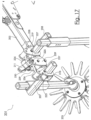
- the in 12 On the left end of the pull element 126 there is a compression spring 130 which strives to press the joint element 129 on the pull element 126 in the direction of the second joint 128 on the clamping lever 119.
- the joint element 129 is slidable in the longitudinal direction of the tension element 126 on the same and can - as can be seen by comparing the 11 with the 12 is understandable - rotate relative to the actuating member 111 about the axis of the first joint 127. At the same time, the joint element 129 cannot move linearly relative to the actuator 111, ie it remains stationary relative to the actuator 111 with regard to its coaxial position with the axis of the first joint 127.
- the actuating element 111 is in its release position, so that the clamping levers 118 and 119 are each in their release position, in which they release the carrier elements 107 and 108 do not lock or clamp in the guide receptacles of the device body 102.
- the distance between the working tools 103, 104 and the device body 102 can be adjusted in this state by linearly displacing the carrier elements 107, 108 in the guide receptacles of the device body 102.
- the carrier elements 107, 108 can be fixed by actuating the locking device.
- the actuator 111 by hand from his in the 11 and 13 shown detachment in his in the 12 , 14 and 15 shown locking position brought. It is pivoted about the pivot joint 125 by a little more than 90°.
- the upper ends of the two clamping levers 118, 119 are attracted to one another.
- the clamping element 118 in 14 subjected to a clockwise torque about the axis of rotation 123 .
- the clamping element 119 is 14 applied with a torque in the counterclockwise direction about the axis of rotation 124. Accordingly, the clamping lever 118 presses the carrier element 107 in 14 to the left, while the clamping lever 119 holds the carrier element 108 in 14 pushes to the right.
- the locking device comprising the actuating member 111, the clamping levers 118, 119 and the pulling element 126 are no longer mechanically connected to the device body 102 after the carrier elements 107, 108 have been completely pulled out of the guide receptacles of the device body 102.
- the function according to the invention ie the joint release or joint fixing of the carrier elements 107, 108 from or to the device body 102, would still be achieved.
- the 16 and 17 show a third embodiment of the present invention in the form of the device 201 according to the invention.
- the reference numerals of the second embodiment according to FIGS Figures 11 to 15 be in 16 and 17 Reference numbers used that have a "2" instead of a "1" in the first of their three digits.
- the 16 and 17 Reference signs are used which correspond to the reference signs in the second and third digits Figures 11 to 15 correspond to the second embodiment, have in the 16 and 17 correspondingly marked parts have the same function as those parts of the second embodiment shown in FIGS Figures 11 to 15 are marked with the same number in the second and third place of their reference number.
- the lever-like actuating member 211 is arranged in a space between the first clamping lever 218 and the second clamping lever 219.
- the actuating member 211 is rotatably mounted about a swivel joint 225 on two bearing plates 239 which are fixed in a rotationally fixed manner on opposite sides of the device body 202 .
- a first pull element 226 designed as a pull rod is articulated on the one hand via the first joint 227 to the actuating element 211 and on the other hand articulated via a second joint 228 to the in 16 upper end of the second clamping lever 219 connected.
- a second tension element 236 designed as a tension rod is articulated on the one hand via a third joint 237 to the in 16 connected to the upper end of the first clamping lever 218 and, on the other hand, connected in an articulated manner via a fourth joint 238 to the actuating member 211 .
- the first joint 227 and the fourth joint 238 are on opposite sides of the pivot joint 225 about which the actuating member 211 can be pivoted.
- the mode of operation of the actuating member 211, the first connecting rod 226, the first joint 227, the second joint 228, the pivot joint 225 and the compression spring 230 is the same as that already described above in connection with the second exemplary embodiment.
- the actuator 211 in 16 pivoted to the left about the pivot joint 225 it passes through the in 17 shown intermediate position on its way to the locking position, not shown for the third embodiment.
- the fourth joint 238 moves in the 16 and 17 To the right.
- the two elongated support elements 207, 208 are pressed in opposite directions against guide surfaces of the guide receptacles in the device body 202.
- the carrier element 207 in the 16 and 17 essentially to the left and the carrier element 208 is essentially pushed to the right.
- FIGS Figures 11 to 15 A fourth embodiment of the present invention in the form of device 301 is shown.
- the reference numerals of the second embodiment according to the Figures 11 to 15 be in 18 and 18 Reference numbers used that have a "3" instead of a "1" in the first of their three digits.
- Figures 11 to 15 correspond to the second embodiment, have in the 18 and 19 correspondingly marked parts have the same function as those parts of the second embodiment shown in FIGS Figures 11 to 15 with the same digit in the second and third Place their reference number are marked.
- the essential differences between the second and the fourth exemplary embodiment will be discussed below.
- the actuating member 311 is arranged to the left of the two clamping levers 318 and 319. Similar to the third exemplary embodiment, the lever-like actuating member 311 is pivotably mounted via a pivot joint 325 on two bearing plates 339 which in turn are non-rotatably fastened on opposite sides of the device body 302 .
- a first pull element 326 designed as a pull rod is connected in an articulated manner to the actuating element 311 via a first joint 327 .
- the other end of the first pulling element 326 is connected in an articulated manner to the first clamping lever 319 via a second joint 328 .
- the first joint 327 and the pivot joint 325 are spaced apart from one another.
- the upper ends of the clamping levers 318 and 319 are connected to one another via a second tension element 336 . That in the 18 and 19 The left end of the pulling element 336 is connected in an articulated manner to the first clamping lever 318 via a third joint 337 . The other end of the pulling element 336 is connected to the upper end of the second clamping lever 319 via a fourth joint 238 . As in the 18 and 19 can be seen, the joint axes of the second joint 328, ie the articulated connection of the first tension element 326 to the first clamping lever 318, and of the third joint 337, ie the articulated connection of the second tension element 336 to the first clamping lever 318, coincide.
- the mode of operation of the actuating member 311, the first pulling element 326, the first joint 327, the second joint 328, the swivel joint 325 and the compression spring 330 is the same as described above in connection with the second embodiment.
Landscapes
- Life Sciences & Earth Sciences (AREA)
- Zoology (AREA)
- Engineering & Computer Science (AREA)
- Mechanical Engineering (AREA)
- Soil Sciences (AREA)
- Environmental Sciences (AREA)
- Agricultural Machines (AREA)
Claims (18)
- Dispositif (1 ; 101 ; 201 ; 301) pour travailler un sol agricole en déplaçant le dispositif (1 ; 101; 201 ; 301) le long du sol dans une direction de déplacement d'un véhicule de traction pour tirer le dispositif (1 ; 101 ; 202 ; 301), dans lequel le dispositif (1 ; 101 ; 202 ; 301) comprend un corps du dispositif (2 ; 102 ; 202 ; 302) ayant un plan longitudinal (LE) qui est sensiblement parallèle à la direction de déplacement, plusieurs outils de travail (3, 4, 5, 6 ; 103, 104 ; 203, 204 ; 303, 304) et plusieurs éléments de support allongés (7, 8, 9, 10 ; 107, 108 ; 207, 208 ; 307, 308) qui portent les outils de travail (3, 4, 5, 6 ; 103, 104 ; 203, 204 ; 303, 304) et sont montés sur le corps du dispositif (2 ; 102 ; 202 ; 302), dans lequel les éléments de support (7, 8, 9, 10 ; 107, 108 ; 207, 208 ; 307, 308) sont respectivement mobiles transversalement au plan longitudinal (LE), de sorte que l'outil de travail respectif (3, 4, 5, 6 ; 103, 104; 203, 204 ; 303, 304) peut être disposé à différentes distances du plan longitudinal (LE), et dans lequel le dispositif (1 ; 101 ; 201 ; 301) comporte un dispositif de blocage pour bloquer les éléments de support (7, 8, 9, 10 ; 107, 108 ; 207, 208 ; 307, 308) sur le corps du dispositif (2 ; 102 ; 202 ; 302), dans lequel le dispositif de blocage comprend un organe d'actionnement (11 ; 111 ; 211 ; 311) par l'actionnement duquel le blocage des plusieurs éléments de support (7, 8, 9, 10 ; 107, 108 ; 207, 208 ; 307, 308) sur le corps du dispositif (2 ; 102 ; 202 ; 302) peut être libéré conjointement ou les plusieurs éléments de support (7, 8, 9, 10 ; 107, 108 ; 207, 208 ; 307, 308) peuvent être fixés conjointement sur le corps du dispositif (2 ; 102 ; 202 ; 302),
caractérisé en ce que
le corps du dispositif (2 ; 101 ; 201 ; 301) présente plusieurs logements de guidage (12, 13, 14) avec des surfaces de guidage respectives (15, 16, 17), dans lequel dans les logements de guidage (12, 13, 14) au moins un des éléments de support (7, 8, 9, 10 ; 107, 108 ; 207, 208 ; 307, 308) est guidé de manière à pouvoir coulisser le long de la surface de guidage respective (15, 16, 17), dans lequel le dispositif de blocage comprend plusieurs leviers de serrage (18, 19, 20, 21 ; 118, 119 ; 218, 219 ; 318, 319) et dans lequel au moins un des plusieurs leviers de serrage (18, 19, 20, 21 ; 118, 119 ; 218, 219 ; 318, 319) est associé à chacun des plusieurs logements de guidage (12, 13, 14), et dans lequel par actionnement de l'organe d'actionnement (11 ; 111 ; 211 ; 311) le levier de serrage respectif (18, 19, 20, 21 ; 118, 119 ; 218, 219 ; 318, 319) passe d'une position de serrage dans laquelle il maintient l'élément de support respectif (7, 8, 9, 10 ; 107, 108 ; 207, 208 ; 307, 308) contre la surface de guidage respective (15, 16, 17) du logement de guidage respectif (12, 13, 14) et le fixe ainsi par friction dans le logement de guidage respectif (12, 13, 14) de manière à ne pas pouvoir le déplacer, à une position de libération, dans laquelle il libère l'élément de support respectif (7, 8, 9, 10 ; 107, 108 ; 207, 208 ; 307, 308), de sorte qu'il peut être déplacé dans le logement de guidage respectif (12, 13, 14) le long de la surface de guidage respective (15, 16, 17), et/ou inversement. - Dispositif (1 ; 101) selon la revendication 1,
caractérisé en ce que
au moyen de l'organe d'actionnement (11 ; 111 ; 211 ; 311), aussi bien le blocage des plusieurs éléments de support (7, 8, 9, 10 ; 107, 108 ; 207, 208 ; 307, 308) sur le corps du dispositif (2 ; 102 ; 202 ; 302) peut être libéré en commun que les plusieurs éléments de support (7, 8, 9, 10 ; 107, 108 ; 207, 208 ; 307 ; 308) peuvent être fixés en commun sur le corps du dispositif (2 ; 102 ; 202 ; 302). - Dispositif selon la revendication 1 ou 2,
caractérisé en ce que
les logements de guidage (12, 13, 14) sont formés chacun par une gaine de guidage qui présente au moins un trou de passage (22) à travers lequel le levier de serrage respectif (18, 19, 20, 21) peut s'engager pour fixer l'élément de support respectif (7, 8, 9, 10). - Dispositif selon l'une des revendications précédentes,
caractérisé en ce que
les plusierus leviers de serrage (18, 19, 20, 21 ; 118, 119 ; 218, 219 ; 318, 319) sont montés à rotation sur le corps du dispositif (2 ; 102 ; 202 ; 302) autour d'un axe de rotation respectif (23, 24, 25 ; 123, 124 ; 223, 224 ; 323, 324). - Dispositif selon la revendication 4,
caractérisé en ce que
le dispositif de blocage comprend au moins une tige de liaison (26), dans lequel chacun des plusieurs leviers de serrage (18, 19, 20, 21) est relié de manière articulée à la tige de liaison (26) par l'intermédiaire d'une articulation respective (27, 28, 29) de telle sorte qu'une section longitudinale (LA) du levier de serrage respectif (18, 19, 20, 21), qui est située entre l'axe de rotation respectif (23, 24, 25) et l'articulation respective (27, 28, 29), sert à fixer l'élément de support respectif (7, 8, 9, 10) dans la position de serrage. - Dispositif selon la revendication 5,
caractérisé en ce que
le dispositif de blocage comprend plusieurs dispositifs d'amortissement (30, 31, 32, 33) qui sont disposés chacun de manière à agir entre la tige de liaison (26) et le levier de serrage respectif (18, 19, 20, 21). - Dispositif selon la revendication 6,
caractérisé en ce que
le dispositif d'amortissement respectif (30, 31, 32, 33) comprend une tige d'appui (34, 35, 36, 37) qui est reliée de manière articulée à la tige de liaison (26) au niveau de l'articulation respective (27, 28, 29) et qui traverse le levier de serrage respectif (18, 19, 20, 21) de telle manière, de manière à pouvoir se déplacer par rapport à lui, et présente un ressort de pression (38, 39, 40, 41), dans lequel le ressort de pression (38, 39, 40, 41) s'appuie d'une part sur la tige d'appui (34, 35, 36, 37) et d'autre part sur le levier de serrage respectif (18, 19, 20, 21). - Dispositif selon l'une des revendications précédentes,
caractérisé en ce que
l'organe d'actionnement (11) est un élément de came avec une surface de commande de came (43), qui est monté sur le corps du dispositif (2) de manière à pouvoir tourner autour d'un axe de came (44), et le dispositif de blocage comprend un levier de réglage (45) qui est monté sur le corps du dispositif (2) de manière à pouvoir tourner autour d'un axe de levier de réglage (46), dans lequel le levier de réglage (45) présente sur un côté de l'axe de levier de réglage (46) une surface d'attaque (47) sur laquelle la surface de commande de came (43) s'attaque. - Dispositif selon la revendication 8 en liaison avec la revendication 5,
caractérisé en ce que
le dispositif de blocage comprend au moins un organe de compensation (48) qui est relié de manière articulée d'une part à la tige de liaison (26) par l'intermédiaire d'une première articulation de compensation (49) et d'autre part au levier de réglage (45) par l'intermédiaire d'une deuxième articulation de compensation (50) sur un côté de l'axe (46) du levier de réglage qui est opposé à la surface d'attaque (47). - Dispositif selon la revendication 8 en combinaison avec la revendication 5,
caractérisé en ce que
la première articulation de compensation (49) coïncide avec l'articulation (27) qui relie de manière articulée la tige de liaison (26) au levier de serrage (18) qui est disposé le plus près du levier de réglage (45). - Dispositif selon la revendication 4,
caractérisé en ce que
l'organe d'actionnement (111 ; 211) est en liaison active avec un premier et un deuxième levier de serrage (118, 119 ; 218, 219) de telle sorte que les extrémités du premier et du deuxième levier de serrage (118, 119 ; 218, 219) qui sont opposées aux éléments de support (107, 108 ; 207, 208) sont tirées l'une vers l'autre dans la position de serrage respective, de sorte que les éléments de support (107, 108 ; 207, 208) associés au premier et au deuxième levier de serrage (118, 119 ; 218, 219) sont repoussés l'un de l'autre dans la position de serrage contre des surfaces de guidage des logements de guidage. - Dispositif selon l'une des revendications précédentes,
caractérisé en ce que
l'organe d'actionnement (111 ; 211) est en liaison active avec un premier et un deuxième levier de serrage (118, 119 ; 218, 219) de telle sorte que les extrémités du premier et du deuxième levier de serrage (118, 119 ; 218, 219) qui sont éloignées des éléments de support (107, 108 ; 207, 208) sont tirées l'une vers l'autre dans la position de serrage respective, de sorte que les éléments de support (107, 108 ; 207, 208) associés au premier et au deuxième levier de serrage (118, 119 ; 218, 219) sont également poussés l'un vers l'autre dans la position de serrage et ainsi contre des surfaces de guidage des logements de guidage. - Dispositif selon la revendication 11 ou 12,
caractérisé en ce que
l'organe d'actionnement (111) est relié de manière articulée au premier levier de serrage (118) par une articulation pivotante (125) et un élément de traction (126) est relié à l'organe d'actionnement (111) par une première articulation (127) ainsi qu'au deuxième levier de serrage (119) par une deuxième articulation (128), dans lequel la première articulation (127) et l'articulation pivotante (125) sont espacées l'une de l'autre, et dans lequel lors du pivotement de l'organe d'actionnement (111) autour de l'axe de l'articulation pivotante (125) d'une position de relâchement, dans laquelle les leviers de serrage (118, 119) se trouvent dans leur position de libération, dans une position de blocage dans laquelle les leviers de serrage (118, 119) se trouvent dans leur position de serrage, une distance entre la première articulation (127) et la deuxième articulation (128) augmente tout d'abord à l'encontre d'une force de rappel élastique, puis atteint une valeur maximale dans une position de point mort de l'organe d'actionnement (111) et diminue finalement à nouveau en raison de l'action de la force de rappel élastique. - Dispositif selon la revendication 11 ou 12,
caractérisé en ce que
l'organe d'actionnement (211) est monté de manière articulée sur le corps du dispositif (202) dans un espace intermédiaire entre le premier et le deuxième levier de serrage (218, 219) par l'intermédiaire d'une articulation pivotante (225), dans lequel un premier élément de traction (226) est relié à l'organe d'actionnement (211) par une première articulation (227) ainsi qu'au deuxième levier de serrage (219) par une deuxième articulation (228), dans lequel la première articulation (227) et l'articulation pivotante (227) sont espacées l'une de l'autre, dans lequel un deuxième élément de traction (236) est relié par une troisième articulation (237) au premier levier de serrage (218) ainsi que par une quatrième articulation (238) à l'organe d'actionnement (211), dans lequel la première articulation (227) et la quatrième articulation (238) sont disposées sur des côtés opposés de l'articulation pivotante (225), et dans lequel, lors du pivotement de l'organe d'actionnement (211) autour de l'axe de l'articulation pivotante (225), d'une position de relâchement, dans laquelle les leviers de serrage (218, 219) se trouvent dans leur position de libération, à une position de blocage, dans laquelle les leviers de serrage (218, 219) se trouvent dans leur position de serrage, une distance entre la première articulation (227) et la deuxième articulation (228) augmente tout d'abord à l'encontre d'une force de rappel élastique, puis atteint une valeur maximale dans une position de point mort de l'organe d'actionnement (211) et finalement diminue à nouveau en raison de l'action de la force de rappel élastique et le deuxième élément de traction (236) tire le premier levier de serrage (218) en direction du deuxième levier de serrage (219). - Dispositif selon la revendication 4,
caractérisé en ce que
l'organe d'actionnement (311) est en liaison active avec un premier et un deuxième levier de serrage (318, 319) de telle sorte que les extrémités du premier et du deuxième levier de serrage (318, 319) qui sont opposées aux éléments de support (307, 308) sont tirées dans la même direction dans la position de serrage respective, de sorte que les éléments de support (307, 308) associés au premier et au deuxième levier de serrage (318, 319) sont pressés dans la position de serrage dans une direction opposée à cette direction contre des surfaces de guidage des logements de guidage. - Dispositif selon l'une des revendications précédentes,
caractérisé en ce que
l'organe d'actionnement (311) est en liaison active avec un premier et un deuxième levier de serrage (318, 319) de telle sorte que les extrémités du premier et du deuxième levier de serrage (318, 319) qui sont opposées aux éléments de support (307, 308) sont tirées dans la même direction dans la position de serrage respective, de sorte que les éléments de support (307, 308) associés au premier et au deuxième levier de serrage (318, 319) sont également poussés dans cette direction et ainsi contre des surfaces de guidage des logements de guidage. - Dispositif selon la revendication 15 ou 16,
caractérisé en ce que
l'organe d'actionnement (311) est monté de manière articulée sur le corps du dispositif (302) à l'extérieur d'un espace intermédiaire entre le premier et le deuxième levier de serrage (318, 319) par l'intermédiaire d'une articulation pivotante (325), dans lequel un premier élément de traction (326) est relié à l'organe d'actionnement (311) par une première articulation (327) ainsi qu'au premier levier de serrage (319) par une deuxième articulation (328), dans lequel la première articulation (327) et l'articulation pivotante (327) sont espacées l'une de l'autre, dans lequel un deuxième élément de traction (336) est relié par une troisième articulation (337) au premier levier de serrage (318) ainsi que par une quatrième articulation (238) au deuxième levier de serrage (319), et dans lequel, lors du pivotement de l'organe d'actionnement (311) autour de l'axe de l'articulation pivotante (325), d'une position de relâchement, dans laquelle les leviers de serrage (318, 319) se trouvent dans leur position de libération, à une position de blocage, dans laquelle les leviers de serrage (318, 319) se trouvent dans leur position de serrage, une distance entre la première articulation (327) et la deuxième articulation (328) augmente d'abord à l'encontre d'une force de rappel élastique, puis atteint une valeur maximale dans une position de point mort de l'organe d'actionnement (311) et diminue finalement à nouveau en raison de l'effet de la force de rappel élastique et le deuxième élément de traction (336) tire le deuxième levier de serrage (319) en direction du premier levier de serrage (319). - Dispositif selon la revendication 13, 14 ou 17,
caractérisé en ce que
la première articulation (127 ; 227 ; 327) présente un élément d'articulation (129 ; 229 ; 329) qui est traversé par l'élément de traction (126) ou le premier élément de traction (226 ; 336) de telle sorte qu'il est mobile dans une direction longitudinale de l'élément de traction (126) ou du premier élément de traction (226 ; 336) par rapport à celui-ci, et la force de rappel élastique est provoquée par au moins un ressort de compression (130 ; 230 ; 330) qui s'appuie sur l'élément de traction (126) ou sur le premier élément de traction (226 ; 326) et qui pousse l'élément d'articulation (129 ; 229 ; 339) en direction de la deuxième articulation (128 ; 228 ; 328).
Applications Claiming Priority (2)
| Application Number | Priority Date | Filing Date | Title |
|---|---|---|---|
| EP20206503.3A EP3994966A1 (fr) | 2020-11-09 | 2020-11-09 | Réglage de l'insert de hachage sur le hachoir |
| PCT/EP2021/081058 WO2022096737A1 (fr) | 2020-11-09 | 2021-11-09 | Dispositif pour travailler un sol agricole |
Publications (2)
| Publication Number | Publication Date |
|---|---|
| EP4040937A1 EP4040937A1 (fr) | 2022-08-17 |
| EP4040937B1 true EP4040937B1 (fr) | 2023-08-23 |
Family
ID=73198198
Family Applications (2)
| Application Number | Title | Priority Date | Filing Date |
|---|---|---|---|
| EP20206503.3A Withdrawn EP3994966A1 (fr) | 2020-11-09 | 2020-11-09 | Réglage de l'insert de hachage sur le hachoir |
| EP21807095.1A Active EP4040937B1 (fr) | 2020-11-09 | 2021-11-09 | Dispositif de travail d'un sol agricole |
Family Applications Before (1)
| Application Number | Title | Priority Date | Filing Date |
|---|---|---|---|
| EP20206503.3A Withdrawn EP3994966A1 (fr) | 2020-11-09 | 2020-11-09 | Réglage de l'insert de hachage sur le hachoir |
Country Status (2)
| Country | Link |
|---|---|
| EP (2) | EP3994966A1 (fr) |
| WO (1) | WO2022096737A1 (fr) |
Family Cites Families (7)
| Publication number | Priority date | Publication date | Assignee | Title |
|---|---|---|---|---|
| FR1006494A (fr) * | 1948-01-22 | 1952-04-23 | Bungartz & Co | Dispositif pour la fixation et le réglage d'outils multiples pour le travail de la terre |
| DE849618C (de) * | 1950-04-04 | 1952-09-15 | Georg Engelbrecht | Pflug mit in der Breite verstellbaren, nach beiden Seiten werfenden Scharen zur Bearbeitung von Weinbergen und Reihenpflanzungen |
| FR1061211A (fr) * | 1952-08-05 | 1954-04-09 | Cultivateur à manoeuvre rapide | |
| FR1503803A (fr) * | 1966-10-13 | 1967-12-01 | Cadre extensible pour machine agricole | |
| CN201100980Y (zh) * | 2007-08-27 | 2008-08-20 | 林广军 | 中耕起垄通用机 |
| US20120061110A1 (en) * | 2009-05-08 | 2012-03-15 | Jose Leoncio Valdes Hernandez | Multicultivator for vertical farming |
| FR2947693B1 (fr) * | 2009-07-10 | 2011-08-05 | Sarl Jean Michel Egretier | Porte-outils a ecartement reglable pour plantations en ligne |
-
2020
- 2020-11-09 EP EP20206503.3A patent/EP3994966A1/fr not_active Withdrawn
-
2021
- 2021-11-09 WO PCT/EP2021/081058 patent/WO2022096737A1/fr not_active Ceased
- 2021-11-09 EP EP21807095.1A patent/EP4040937B1/fr active Active
Also Published As
| Publication number | Publication date |
|---|---|
| EP4040937A1 (fr) | 2022-08-17 |
| EP3994966A1 (fr) | 2022-05-11 |
| WO2022096737A1 (fr) | 2022-05-12 |
Similar Documents
| Publication | Publication Date | Title |
|---|---|---|
| EP0316923B1 (fr) | Repartisseur pour ensileuse | |
| DE2950722C2 (de) | Stellvorrichtung für den Dreschkorb eines Axialflußmähdreschers | |
| EP0738458A2 (fr) | Appareil agricole avec dispositif pour ajuster la pression des outils sur le sol | |
| AT510969B1 (de) | Werkzeughalterung für abkantpresse | |
| EP4028599B1 (fr) | Élément de préhension | |
| DE102004017080A1 (de) | Schneidwerk für / an landwirtschaftlichen Erntefahrzeugen | |
| EP3274278A1 (fr) | Mécanisme de pliage pour un moyen de transport | |
| DE2357860C2 (de) | Kupplung | |
| EP3843522B1 (fr) | Engin agricole à cadre télescopique | |
| DE3838936C2 (fr) | ||
| EP2932817B1 (fr) | Appareil de traitement des sols | |
| WO2022096737A1 (fr) | Dispositif pour travailler un sol agricole | |
| EP4424128A1 (fr) | Dispositif de support destiné à être monté sur un châssis de machine d'une machine de travail agricole, machine de travail agricole dotée d'un tel dispositif de support et procédé de réglage d'au moins un dispositif de machine de travail agricole | |
| EP1500322B1 (fr) | Dispositif pour le travail du sol | |
| EP1253994B1 (fr) | Dispositif de serrage | |
| DE102004018591B4 (de) | Bodenbearbeitungsgerät mit Winkelverstellung | |
| EP4176701B1 (fr) | Dispositif de fixation d'au moins un outil agricole à un élément porteur | |
| DE69206929T2 (de) | Heuwerbungsmaschine mit verstellbaren Rädern | |
| DE102021101421B3 (de) | Ernteeinrichtung | |
| EP0123067A1 (fr) | Dispositif de sécurité contre les pierres pour charrues réversibles | |
| AT527100B1 (de) | Landwirtschaftliche Maschine | |
| EP4278875B1 (fr) | Outil pour la culture des champs | |
| EP0511471B1 (fr) | Dispositif pour le montage ajustable d'un élément agricole | |
| DE2447921A1 (de) | Vorrichtung zum raeumen von flaechen, insbesondere forstflaechen | |
| DD249172A5 (de) | Landwirtschaftliches geraet mit einem rahmenteil und einem werkzeugrahmen |
Legal Events
| Date | Code | Title | Description |
|---|---|---|---|
| STAA | Information on the status of an ep patent application or granted ep patent |
Free format text: STATUS: UNKNOWN |
|
| STAA | Information on the status of an ep patent application or granted ep patent |
Free format text: STATUS: THE INTERNATIONAL PUBLICATION HAS BEEN MADE |
|
| PUAI | Public reference made under article 153(3) epc to a published international application that has entered the european phase |
Free format text: ORIGINAL CODE: 0009012 |
|
| STAA | Information on the status of an ep patent application or granted ep patent |
Free format text: STATUS: REQUEST FOR EXAMINATION WAS MADE |
|
| 17P | Request for examination filed |
Effective date: 20220510 |
|
| AK | Designated contracting states |
Kind code of ref document: A1 Designated state(s): AL AT BE BG CH CY CZ DE DK EE ES FI FR GB GR HR HU IE IS IT LI LT LU LV MC MK MT NL NO PL PT RO RS SE SI SK SM TR |
|
| GRAP | Despatch of communication of intention to grant a patent |
Free format text: ORIGINAL CODE: EPIDOSNIGR1 |
|
| STAA | Information on the status of an ep patent application or granted ep patent |
Free format text: STATUS: GRANT OF PATENT IS INTENDED |
|
| DAV | Request for validation of the european patent (deleted) | ||
| DAX | Request for extension of the european patent (deleted) | ||
| INTG | Intention to grant announced |
Effective date: 20230510 |
|
| GRAS | Grant fee paid |
Free format text: ORIGINAL CODE: EPIDOSNIGR3 |
|
| GRAA | (expected) grant |
Free format text: ORIGINAL CODE: 0009210 |
|
| STAA | Information on the status of an ep patent application or granted ep patent |
Free format text: STATUS: THE PATENT HAS BEEN GRANTED |
|
| P01 | Opt-out of the competence of the unified patent court (upc) registered |
Effective date: 20230616 |
|
| AK | Designated contracting states |
Kind code of ref document: B1 Designated state(s): AL AT BE BG CH CY CZ DE DK EE ES FI FR GB GR HR HU IE IS IT LI LT LU LV MC MK MT NL NO PL PT RO RS SE SI SK SM TR |
|
| REG | Reference to a national code |
Ref country code: GB Ref legal event code: FG4D Free format text: NOT ENGLISH |
|
| REG | Reference to a national code |
Ref country code: CH Ref legal event code: EP |
|
| REG | Reference to a national code |
Ref country code: DE Ref legal event code: R096 Ref document number: 502021001333 Country of ref document: DE |
|
| REG | Reference to a national code |
Ref country code: IE Ref legal event code: FG4D Free format text: LANGUAGE OF EP DOCUMENT: GERMAN |
|
| REG | Reference to a national code |
Ref country code: LT Ref legal event code: MG9D |
|
| REG | Reference to a national code |
Ref country code: NL Ref legal event code: MP Effective date: 20230823 |
|
| PG25 | Lapsed in a contracting state [announced via postgrant information from national office to epo] |
Ref country code: GR Free format text: LAPSE BECAUSE OF FAILURE TO SUBMIT A TRANSLATION OF THE DESCRIPTION OR TO PAY THE FEE WITHIN THE PRESCRIBED TIME-LIMIT Effective date: 20231124 |
|
| PG25 | Lapsed in a contracting state [announced via postgrant information from national office to epo] |
Ref country code: IS Free format text: LAPSE BECAUSE OF FAILURE TO SUBMIT A TRANSLATION OF THE DESCRIPTION OR TO PAY THE FEE WITHIN THE PRESCRIBED TIME-LIMIT Effective date: 20231223 |
|
| PG25 | Lapsed in a contracting state [announced via postgrant information from national office to epo] |
Ref country code: SE Free format text: LAPSE BECAUSE OF FAILURE TO SUBMIT A TRANSLATION OF THE DESCRIPTION OR TO PAY THE FEE WITHIN THE PRESCRIBED TIME-LIMIT Effective date: 20230823 Ref country code: RS Free format text: LAPSE BECAUSE OF FAILURE TO SUBMIT A TRANSLATION OF THE DESCRIPTION OR TO PAY THE FEE WITHIN THE PRESCRIBED TIME-LIMIT Effective date: 20230823 Ref country code: PT Free format text: LAPSE BECAUSE OF FAILURE TO SUBMIT A TRANSLATION OF THE DESCRIPTION OR TO PAY THE FEE WITHIN THE PRESCRIBED TIME-LIMIT Effective date: 20231226 Ref country code: NO Free format text: LAPSE BECAUSE OF FAILURE TO SUBMIT A TRANSLATION OF THE DESCRIPTION OR TO PAY THE FEE WITHIN THE PRESCRIBED TIME-LIMIT Effective date: 20231123 Ref country code: NL Free format text: LAPSE BECAUSE OF FAILURE TO SUBMIT A TRANSLATION OF THE DESCRIPTION OR TO PAY THE FEE WITHIN THE PRESCRIBED TIME-LIMIT Effective date: 20230823 Ref country code: LV Free format text: LAPSE BECAUSE OF FAILURE TO SUBMIT A TRANSLATION OF THE DESCRIPTION OR TO PAY THE FEE WITHIN THE PRESCRIBED TIME-LIMIT Effective date: 20230823 Ref country code: LT Free format text: LAPSE BECAUSE OF FAILURE TO SUBMIT A TRANSLATION OF THE DESCRIPTION OR TO PAY THE FEE WITHIN THE PRESCRIBED TIME-LIMIT Effective date: 20230823 Ref country code: IS Free format text: LAPSE BECAUSE OF FAILURE TO SUBMIT A TRANSLATION OF THE DESCRIPTION OR TO PAY THE FEE WITHIN THE PRESCRIBED TIME-LIMIT Effective date: 20231223 Ref country code: HR Free format text: LAPSE BECAUSE OF FAILURE TO SUBMIT A TRANSLATION OF THE DESCRIPTION OR TO PAY THE FEE WITHIN THE PRESCRIBED TIME-LIMIT Effective date: 20230823 Ref country code: GR Free format text: LAPSE BECAUSE OF FAILURE TO SUBMIT A TRANSLATION OF THE DESCRIPTION OR TO PAY THE FEE WITHIN THE PRESCRIBED TIME-LIMIT Effective date: 20231124 Ref country code: FI Free format text: LAPSE BECAUSE OF FAILURE TO SUBMIT A TRANSLATION OF THE DESCRIPTION OR TO PAY THE FEE WITHIN THE PRESCRIBED TIME-LIMIT Effective date: 20230823 |
|
| PG25 | Lapsed in a contracting state [announced via postgrant information from national office to epo] |
Ref country code: PL Free format text: LAPSE BECAUSE OF FAILURE TO SUBMIT A TRANSLATION OF THE DESCRIPTION OR TO PAY THE FEE WITHIN THE PRESCRIBED TIME-LIMIT Effective date: 20230823 |
|
| PG25 | Lapsed in a contracting state [announced via postgrant information from national office to epo] |
Ref country code: ES Free format text: LAPSE BECAUSE OF FAILURE TO SUBMIT A TRANSLATION OF THE DESCRIPTION OR TO PAY THE FEE WITHIN THE PRESCRIBED TIME-LIMIT Effective date: 20230823 |
|
| PG25 | Lapsed in a contracting state [announced via postgrant information from national office to epo] |
Ref country code: SM Free format text: LAPSE BECAUSE OF FAILURE TO SUBMIT A TRANSLATION OF THE DESCRIPTION OR TO PAY THE FEE WITHIN THE PRESCRIBED TIME-LIMIT Effective date: 20230823 Ref country code: RO Free format text: LAPSE BECAUSE OF FAILURE TO SUBMIT A TRANSLATION OF THE DESCRIPTION OR TO PAY THE FEE WITHIN THE PRESCRIBED TIME-LIMIT Effective date: 20230823 Ref country code: ES Free format text: LAPSE BECAUSE OF FAILURE TO SUBMIT A TRANSLATION OF THE DESCRIPTION OR TO PAY THE FEE WITHIN THE PRESCRIBED TIME-LIMIT Effective date: 20230823 Ref country code: EE Free format text: LAPSE BECAUSE OF FAILURE TO SUBMIT A TRANSLATION OF THE DESCRIPTION OR TO PAY THE FEE WITHIN THE PRESCRIBED TIME-LIMIT Effective date: 20230823 Ref country code: DK Free format text: LAPSE BECAUSE OF FAILURE TO SUBMIT A TRANSLATION OF THE DESCRIPTION OR TO PAY THE FEE WITHIN THE PRESCRIBED TIME-LIMIT Effective date: 20230823 Ref country code: CZ Free format text: LAPSE BECAUSE OF FAILURE TO SUBMIT A TRANSLATION OF THE DESCRIPTION OR TO PAY THE FEE WITHIN THE PRESCRIBED TIME-LIMIT Effective date: 20230823 Ref country code: SK Free format text: LAPSE BECAUSE OF FAILURE TO SUBMIT A TRANSLATION OF THE DESCRIPTION OR TO PAY THE FEE WITHIN THE PRESCRIBED TIME-LIMIT Effective date: 20230823 |
|
| REG | Reference to a national code |
Ref country code: DE Ref legal event code: R097 Ref document number: 502021001333 Country of ref document: DE |
|
| PG25 | Lapsed in a contracting state [announced via postgrant information from national office to epo] |
Ref country code: IT Free format text: LAPSE BECAUSE OF FAILURE TO SUBMIT A TRANSLATION OF THE DESCRIPTION OR TO PAY THE FEE WITHIN THE PRESCRIBED TIME-LIMIT Effective date: 20230823 |
|
| PLBE | No opposition filed within time limit |
Free format text: ORIGINAL CODE: 0009261 |
|
| STAA | Information on the status of an ep patent application or granted ep patent |
Free format text: STATUS: NO OPPOSITION FILED WITHIN TIME LIMIT |
|
| PG25 | Lapsed in a contracting state [announced via postgrant information from national office to epo] |
Ref country code: MC Free format text: LAPSE BECAUSE OF FAILURE TO SUBMIT A TRANSLATION OF THE DESCRIPTION OR TO PAY THE FEE WITHIN THE PRESCRIBED TIME-LIMIT Effective date: 20230823 |
|
| PG25 | Lapsed in a contracting state [announced via postgrant information from national office to epo] |
Ref country code: LU Free format text: LAPSE BECAUSE OF NON-PAYMENT OF DUE FEES Effective date: 20231109 |
|
| 26N | No opposition filed |
Effective date: 20240524 |
|
| PG25 | Lapsed in a contracting state [announced via postgrant information from national office to epo] |
Ref country code: MC Free format text: LAPSE BECAUSE OF FAILURE TO SUBMIT A TRANSLATION OF THE DESCRIPTION OR TO PAY THE FEE WITHIN THE PRESCRIBED TIME-LIMIT Effective date: 20230823 Ref country code: LU Free format text: LAPSE BECAUSE OF NON-PAYMENT OF DUE FEES Effective date: 20231109 Ref country code: SI Free format text: LAPSE BECAUSE OF FAILURE TO SUBMIT A TRANSLATION OF THE DESCRIPTION OR TO PAY THE FEE WITHIN THE PRESCRIBED TIME-LIMIT Effective date: 20230823 |
|
| REG | Reference to a national code |
Ref country code: BE Ref legal event code: MM Effective date: 20231130 |
|
| REG | Reference to a national code |
Ref country code: IE Ref legal event code: MM4A |
|
| PG25 | Lapsed in a contracting state [announced via postgrant information from national office to epo] |
Ref country code: IE Free format text: LAPSE BECAUSE OF NON-PAYMENT OF DUE FEES Effective date: 20231109 |
|
| PG25 | Lapsed in a contracting state [announced via postgrant information from national office to epo] |
Ref country code: BE Free format text: LAPSE BECAUSE OF NON-PAYMENT OF DUE FEES Effective date: 20231130 |
|
| PG25 | Lapsed in a contracting state [announced via postgrant information from national office to epo] |
Ref country code: IE Free format text: LAPSE BECAUSE OF NON-PAYMENT OF DUE FEES Effective date: 20231109 Ref country code: BE Free format text: LAPSE BECAUSE OF NON-PAYMENT OF DUE FEES Effective date: 20231130 |
|
| PG25 | Lapsed in a contracting state [announced via postgrant information from national office to epo] |
Ref country code: BG Free format text: LAPSE BECAUSE OF FAILURE TO SUBMIT A TRANSLATION OF THE DESCRIPTION OR TO PAY THE FEE WITHIN THE PRESCRIBED TIME-LIMIT Effective date: 20230823 |
|
| PG25 | Lapsed in a contracting state [announced via postgrant information from national office to epo] |
Ref country code: BG Free format text: LAPSE BECAUSE OF FAILURE TO SUBMIT A TRANSLATION OF THE DESCRIPTION OR TO PAY THE FEE WITHIN THE PRESCRIBED TIME-LIMIT Effective date: 20230823 |
|
| PG25 | Lapsed in a contracting state [announced via postgrant information from national office to epo] |
Ref country code: CY Free format text: LAPSE BECAUSE OF FAILURE TO SUBMIT A TRANSLATION OF THE DESCRIPTION OR TO PAY THE FEE WITHIN THE PRESCRIBED TIME-LIMIT; INVALID AB INITIO Effective date: 20211109 |
|
| REG | Reference to a national code |
Ref country code: CH Ref legal event code: U11 Free format text: ST27 STATUS EVENT CODE: U-0-0-U10-U11 (AS PROVIDED BY THE NATIONAL OFFICE) Effective date: 20251201 |
|
| PG25 | Lapsed in a contracting state [announced via postgrant information from national office to epo] |
Ref country code: TR Free format text: LAPSE BECAUSE OF FAILURE TO SUBMIT A TRANSLATION OF THE DESCRIPTION OR TO PAY THE FEE WITHIN THE PRESCRIBED TIME-LIMIT Effective date: 20230823 |
|
| PGFP | Annual fee paid to national office [announced via postgrant information from national office to epo] |
Ref country code: DE Payment date: 20251029 Year of fee payment: 5 |
|
| PGFP | Annual fee paid to national office [announced via postgrant information from national office to epo] |
Ref country code: AT Payment date: 20260113 Year of fee payment: 5 |
|
| PGFP | Annual fee paid to national office [announced via postgrant information from national office to epo] |
Ref country code: FR Payment date: 20251126 Year of fee payment: 5 |
|
| PGFP | Annual fee paid to national office [announced via postgrant information from national office to epo] |
Ref country code: CH Payment date: 20251201 Year of fee payment: 5 |
|
| PG25 | Lapsed in a contracting state [announced via postgrant information from national office to epo] |
Ref country code: HU Free format text: LAPSE BECAUSE OF FAILURE TO SUBMIT A TRANSLATION OF THE DESCRIPTION OR TO PAY THE FEE WITHIN THE PRESCRIBED TIME-LIMIT; INVALID AB INITIO Effective date: 20211109 |