EP4041971B1 - Kraftfahrzeugschloss, insbesondere kraftfahrzeugtürschloss - Google Patents
Kraftfahrzeugschloss, insbesondere kraftfahrzeugtürschloss Download PDFInfo
- Publication number
- EP4041971B1 EP4041971B1 EP20792524.9A EP20792524A EP4041971B1 EP 4041971 B1 EP4041971 B1 EP 4041971B1 EP 20792524 A EP20792524 A EP 20792524A EP 4041971 B1 EP4041971 B1 EP 4041971B1
- Authority
- EP
- European Patent Office
- Prior art keywords
- lever
- control
- motor vehicle
- crash
- contour
- Prior art date
- Legal status (The legal status is an assumption and is not a legal conclusion. Google has not performed a legal analysis and makes no representation as to the accuracy of the status listed.)
- Active
Links
Images


Classifications
-
- E—FIXED CONSTRUCTIONS
- E05—LOCKS; KEYS; WINDOW OR DOOR FITTINGS; SAFES
- E05B—LOCKS; ACCESSORIES THEREFOR; HANDCUFFS
- E05B77/00—Vehicle locks characterised by special functions or purposes
- E05B77/02—Vehicle locks characterised by special functions or purposes for accident situations
- E05B77/04—Preventing unwanted lock actuation, e.g. unlatching, at the moment of collision
- E05B77/06—Preventing unwanted lock actuation, e.g. unlatching, at the moment of collision by means of inertial forces
-
- E—FIXED CONSTRUCTIONS
- E05—LOCKS; KEYS; WINDOW OR DOOR FITTINGS; SAFES
- E05B—LOCKS; ACCESSORIES THEREFOR; HANDCUFFS
- E05B83/00—Vehicle locks specially adapted for particular types of wing or vehicle
- E05B83/36—Locks for passenger or like doors
Definitions
- the invention relates to a motor vehicle lock, in particular a motor vehicle door lock, with a locking mechanism consisting essentially of a rotary latch and a pawl, furthermore with an actuating lever mechanism for releasing the locking mechanism, and with a crash unit which disables the actuating lever mechanism and/or the locking mechanism at least when deceleration forces of a predetermined size and direction occur, for example in the event of an accident (crash), the crash unit being equipped with at least one spring which acts on a lever.
- the locking mechanism consists essentially of a rotary latch and a pawl. A so-called single locking mechanism is then implemented. In principle, a multiple locking mechanism can also be provided. In this case, a rotary latch, a comfort pawl securing the rotary latch and a locking pawl for securing the comfort pawl are typically implemented. Alternatively, you can also work with an additional first catch and the pawl. In all of these cases, deceleration forces occurring in connection with an accident can result in the locking mechanism being opened unintentionally. Because the deceleration forces in question act here - also - on the actuating lever system for triggering the locking mechanism.
- the crash unit prevents such unintentional openings of the locking mechanism from occurring.
- the locking mechanism or the actuating lever system acting on the locking mechanism is rendered ineffective in the event of a crash.
- the operating lever system is usually made up of one or more levers. Usually, an inside operating lever, an outside operating lever and a release lever are used as a minimum.
- the actuating lever mechanism often has one or more clutch levers, with the help of which individual securing positions of the actuating lever mechanism can be realized.
- the locking mechanism is usually opened via the release lever as part of the actuating lever system.
- the release lever typically engages the pawl, a comfort pawl or both pawls and lifts the pawl or the several pawls in particular from the associated rotary latch, so that as a result the locking mechanism can open with spring support.
- a motor vehicle lock is realized in which the crash unit or a blocking means realized at this point is designed to be changeable in terms of its shape.
- the blocking means In its normal form, the blocking means is effected with the actuating lever mechanism without any function.
- a locking form of the locking means corresponds to the actuating lever system and/or the locking mechanism being rendered ineffective. In this way, the overall functional reliability is to be increased with a simple structure at the same time.
- the blocking means which can be changed in shape, is structurally relatively complex.
- the invention is based on the technical problem of further developing such a motor vehicle lock and in particular a motor vehicle door lock in such a way that the design is simplified while the functionality remains unchanged, and a particularly cost-effective variant is therefore available.
- a generic motor vehicle lock and in particular a motor vehicle door lock is characterized within the scope of the invention in that the lever as part of the crash unit is designed as a control lever of the crash unit, which is set up to control a clutch lever of the actuating lever system, the clutch lever continuously assuming its "locked” position and only in normal operation by the control lever then moved together with the actuating lever system into its "unlocked” position.
- the crash lock that is implemented is initially made up of the clutch lever and the control lever.
- a mass inertia lever is usually also assigned to the control lever. In principle, however, the control lever and the mass inertia lever can also coincide functionally.
- the clutch lever With the help of the control lever, the clutch lever is now consistently held in its "locked” position.
- the clutch lever is not only a part of the crash unit, but also a part of the actuating lever system. In its "locked” position, the clutch lever ensures - as usual - that the actuating lever system is mechanically interrupted, so that its application does not typically correspond to actuating movements of the release lever, because the application of the actuating lever system in relation to the locking mechanism is empty.
- the closed locking mechanism thus remains in its closed state.
- the "unlocked" position of the clutch lever corresponds to the actuating lever system providing a continuous mechanical connection up to the release lever, so that actuation of the actuating lever system corresponds to an actuation of the release lever and thus to the release of the locking mechanism.
- the clutch lever is now consistently held in its "locked” position. This also and especially applies in the event of a crash. Because in the event of a crash, the control lever ensures that the clutch lever remains in its "locked” position, either through its inertia alone or through the combined inertia of the control lever in conjunction with the inertia lever. Any loading of the actuating lever system is absorbed by the spring. This is because the control lever and an actuating lever of the actuating lever mechanism are coupled to one another using the spring.
- the spring between the actuating lever and the control lever ensures that the actuating lever can be adjusted, while the control lever nevertheless maintains its position due to its inertia. This also applies to the clutch lever, which is controlled with the help of the control lever and remains in its "locked" position.
- the crash unit according to the invention essentially has the control lever that controls the clutch lever.
- the clutch lever is usually implemented in any case in order to be able to represent different securing positions of the actuating lever system, such as "locked” or "unlocked”.
- the clutch lever is now also included in the crash lock or constitutes a component of the crash unit. This is ensured by the control lever that controls the clutch lever and is additionally provided, which ensures in the event of a crash due to its own inertia or inertia in conjunction with the optional inertia lever that the clutch lever retains its "locked” position unchanged.
- control lever and the actuating lever are mounted coaxially with one another.
- control lever advantageously has a control contour for a control pin of the clutch lever that engages in the control contour.
- the clutch lever is controlled by the control lever.
- the clutch lever is generally mounted such that it can rotate about an axis parallel to the axis of the control lever.
- the clutch lever is rotatably mounted on the release lever as part of the actuating lever mechanism.
- the clutch lever can easily be transferred to an “unlocked” position mechanically coupling the actuating lever to the release lever, as well as to its consistently assumed “locked” position, in which the mechanical connection from the actuating lever to the release lever is interrupted.
- the clutch lever generally interacts with a contour on the release lever in such a way that, in its pivoted-in or "unlocked” state, the actuating lever acts on the release lever in normal operation.
- an actuation of the actuating lever consequently leads to the actuating lever entraining and also being able to entrain the control lever via the interposed spring.
- the joint movement of the actuating lever and control lever now leads to the control contour of the control lever engaging control pin on the clutch lever in a contour area of the control contour engages, which pivoting of the clutch lever and thus taking its "unlocked” position allows.
- the pivoted-in state of the clutch lever corresponds here to the clutch lever being able to interact with the contour on the release lever, generally resting against the contour.
- a continuous mechanical connection is realized from the actuating lever via the control lever, the clutch lever and finally the release lever to the locking mechanism, so that actuation of the actuating lever and thus the actuating lever system as a whole triggers the locking mechanism, typically leading to its opening.
- the clutch lever retains its pivoted position in relation to the contour in question on the release lever. This corresponds to the "locked" position of the clutch lever that is consistently assumed and maintained.
- the actuating lever is decoupled from the control lever and can perform pivoting movements relative to the control lever. During these pivoting movements, the spring coupling the actuating lever to the control lever is compressed or lengthened, depending on the design.
- the control lever is usually coupled to a mass inertia lever.
- the control lever maintains its position with the help of the mass inertia lever. In this maintained position of the control lever, it ensures that the clutch lever is fixed in its "locked” position via the control lever.
- the clutch lever which is still in the "locked” position, ensures in the event of a crash that, as desired, there is no continuous mechanical connection from the actuating lever system to the release lever, so that the locking mechanism also retains its closed position in the event of a crash.
- the Inertia levers typically have a contour for receiving a pin of the control lever.
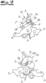
- a motor vehicle lock is shown in the figures, which is a motor vehicle door lock.
- the motor vehicle lock or motor vehicle door lock is equipped for this purpose with a locking mechanism from rotary latch 1 and pawl 2, which is in the 1 is only indicated in supervision or in the Figures 1A to 1C is reproduced only in section in the form of the pawl 2.
- an actuating lever system 3, 4, 5, 7 is provided and implemented.
- the operating lever system 3, 4, 5, 7 is composed according to the exemplary embodiment and not restrictively of an external operating lever 3, an internal operating lever 4 and a release lever 5, which are mounted coaxially with respect to a common axis 6 in a lock housing, not shown in detail.
- the actuating lever system 3, 4, 5, 7 includes a clutch lever 7, which is mounted on the release lever 5 about a further axis 8 parallel to the axis 6.
- the external activation lever 3 and the release lever 5 as well as the clutch lever 7 are primarily relevant for the following considerations. In fact, the following considerations can also be transferred to the inside actuating lever 4 .
- the external operating lever 3 is connected to an external handle, not shown, respectively an external door handle, with the aid of which the external operating lever 3 for triggering the locking mechanism 1, 2 is connected in such a way to a Figure 1A indicated force F is applied so that the external actuating lever 3 performs a clockwise movement about its axis 6, as indicated in the figures.
- the release lever 5 is able to release the pawl 2 in the illustration according to the Figures 1A to 1C to the left according to the arrow indicated, so that the pawl 2 pivots clockwise in the view of the locking mechanism 1, 2, thereby releasing the previously locked rotary latch 1.
- the rotary latch 1 then swings open with the assistance of spring force and releases a previously caught locking bolt.
- the locking mechanism 1, 2 is open. This corresponds to the "unlocked" state of the clutch lever 7, as shown in the individual illustrations according to FIG Figures 1B and 1C is shown.
- crash unit 3, 7, 9, 10, 11 ensures that the locking mechanism 1, 2 or the actuating lever mechanism 3, 4, 5 , 7 is invalidated.
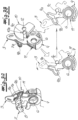
- the in the Figures 3A and 3B crash unit 3, 7, 9, 10, 11 shown in detail is based on the embodiment of an actuating lever or the External operating lever 3 and the clutch lever 7 together, which also belong to the operating lever system 3, 4, 5, 7.
- a control lever 9 to be described in more detail below is also implemented, which is set up to control the clutch lever 7 .
- the crash unit 3, 7, 9, 10, 11 also includes a mass inertia lever 10 that acts on the control lever 9.
- a component of the crash unit 3, 7, 9, 10, 11 is a spring 11, which elastically couples the actuating lever or external actuating lever 3 on the one hand and the control lever 9 on the other.
- the control lever 9 of the crash unit 3, 7, 9, 10, 11 is set up to control the clutch lever 7.
- the control lever 9 has a particular in the Figures 3A and 3B illustrated control contour 9a, 9b.
- the control contour 9a, 9b is equipped with two contour areas 9a, 9b which, according to the exemplary embodiment, enclose an obtuse angle between them, so that the control pin 7a is fixed in the area of an apex of the obtuse angle. This corresponds to the consistently occupied position "locked" of the clutch lever 7, as shown in FIG Figure 1A and the Figures 2A to 2C is shown in detail.
- a counterclockwise movement of the clutch lever 7 about its axis 8 on the release lever 5 corresponds to this to be able to
- the clutch lever 7 moves in its "unlocked” or pivoted position against the contour 3a in question, so that the actuating lever or external actuating lever 3 and the release lever 5 are mechanically connected to one another.
- Any pivoting movements of the external actuating lever 3 about its axis 6 in the indicated clockwise direction to release the locking mechanism 1, 2 are consequently transferred to the release lever 5, which is also pivoted clockwise about the common axis 6, thereby disengaging the pawl 2 from its engagement with the rotary latch 1 during the transition from the Figure 1A to the Figure 1B and on to Figure 1C can take off.
- the clutch lever 7 or its axis 8 is oriented parallel to the axis 6 of the control lever.
- the axis 6 of the control lever also acts as an axis for the release lever 5 and the actuating lever or external actuating lever 3.
- the force F acting on the external operating lever 3 by an action on an external handle for example, pivots the operating lever or external operating lever 3 in the indicated clockwise direction about its axis 6 .
- the external control lever 3 is coupled to the control lever 9 via the spring 11, a leads into the Figures 1A to 1C shown normal operation to the fact that the control lever 9 follows the clockwise movement of the external control lever 3.
- the joint pivoting movement of the actuating lever or external actuating lever 3 together with the control lever 9 in normal operation and clockwise around the common axis 6 means that the control pin 7a of the clutch lever 7 can deviate into the contour area 9a of the control lever 9, so that as a result the clutch lever 7 can be moved counterclockwise around the axis 8 to the position after the Figure 1B can swing in.
- the clutch lever 7 comes to rest on the contour 3a of the external operating lever 3 and the external operating lever 3 and the release lever 5 are consequently mechanically coupled to one another by the pivoted-in clutch lever 7 in its “unlocked” position.
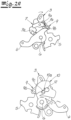
- the crash case is now in the function sequence after the Figures 2A to 2C shown.
- the actuation lever or external actuation lever 3 can now be acted upon again in the sense of opening the locking mechanism 1, 2. That is, the external operating lever 3 is in the transition from the Figure 2A to the Figure 2B again - by the deceleration forces - applied clockwise about its axis 6.
- the control lever 9 remains at rest. This is ensured by the inertia of the control lever 9, which is realized according to the exemplary embodiment through its interaction with the inertia lever 10.
- the control lever 9 can also be designed in such a way that, due to its own mass, it has the required mass inertia in order to withstand the (rapid) movements of the external activation lever 3 in the event of a crash.
- the control lever 9 maintains its position in the event of a crash by means of the mass inertia lever 10 .
- the mass inertia lever 10 is rotatably mounted about its own axis 12 .
- the control lever 9 fixes the clutch lever 7 in its “locked” position in the event of a crash. That is, the clutch lever 7 retains consistently in the event of a crash and in all functional representations after Figures 2A to 2C consistently in its "locked” position.
- the actuating lever system 3, 4, 5, 7 for triggering the locking mechanism 1, 2 is interrupted, so that the locking mechanism 1, 2 retains its closed position as desired in the event of a crash.
- the inertia lever 10 has a contour 10a for receiving a pin 9c on the control lever 9.
- the pin 9c of the control lever 9 extends predominantly perpendicularly to the planar extent of the control lever 9 and engages in the contour 10a of the inertia lever 10.
- the axis 12 of the mass inertia lever 10 runs parallel to the axes 6, 8.
- the external actuating lever 3 After the elimination of the deceleration forces, the external actuating lever 3 returns - acted upon by the spring 11 - to its original position after the Figure 2A (back again.
- the design is such that the pivoting movement of the external actuating lever 3 takes the control lever 9 with it via the spring 11 . Since the pivoting movement in normal operation is slowly below a limit speed to be determined by the dimensioning of the individual components, the interposed spring 11 ensures that the control lever 9 can follow the pivoting movements of the external actuating lever 3 .
- the mass inertia lever 10 which is also carried along during the pivoting movement via the pin 9c on the control lever 9 by engaging in the contour 10a and pivots about its axis 12 in normal operation.
- the control lever 9 can pivot in normal operation about the common axis 6 with the external control lever 3 in a clockwise direction, so that - as described - the control pin 7a on the clutch lever 7 reaches the contour area 9a of the control lever 9 and consequently into the "unlocked" position as shown in FIGS Figures 1B and 1C can swing in.
- the locking mechanism 1, 2 can consequently be opened during normal operation.
- the clutch lever 7 takes consistently in its rest position as well as in the Figures 2A to 2C the crash shown in the "locked" position. In the event of a crash, this is ensured by the control lever 9 which, according to the exemplary embodiment, builds up the required mass inertia forces in conjunction with the mass inertia lever 10 .
Landscapes
- Lock And Its Accessories (AREA)
- Mechanical Control Devices (AREA)
Description
- Die Erfindung betrifft ein Kraftfahrzeugschloss, insbesondere Kraftfahrzeugtürschloss, mit einem Gesperre aus im Wesentlichen Drehfalle und Sperrklinke, ferner mit einem Betätigungshebelwerk zum Auslösen des Gesperres, und mit einer Crasheinheit, welche das Betätigungshebelwerk und/oder das Gesperre zumindest bei auftretenden Verzögerungskräften vorgegebener Größe und Richtung, beispielsweise bei einem Unfall (Crashfall) unwirksam setzt, wobei die Crasheinheit mit zumindest einer Feder ausgerüstet ist, welche einen Hebel beaufschlagt.
- Das Gesperre setzt sich im Wesentlichen aus Drehfalle und Sperrklinke zusammen. Dann ist ein sogenanntes Einfachgesperre realisiert. Grundsätzlich kann auch ein Mehrfachgesperre vorgesehen werden. In diesem Fall ist typischerweise eine Drehfalle, eine die Drehfalle sichernde Komfortklinke und eine Sperrklinke zur Sicherung der Komfortklinke realisiert. Es kann alternativ auch mit einer zusätzlichen Vorrastklinke und der Sperrklinke gearbeitet werden. In diesen sämtlichen Fällen kann es bei im Zusammenhang mit einem Unfall auftretenden Verzögerungskräften dazu kommen, dass das Gesperre unbeabsichtigt geöffnet wird. Denn die fraglichen Verzögerungskräfte wirken dabei - auch - auf das Betätigungshebelwerk zum Auslösen des Gesperres ein.
- Mit Hilfe der Crasheinheit wird in einem solchen Fall verhindert, dass es zu solchen unbeabsichtigten Öffnungen des Gesperres kommt. Dazu wird das Gesperre respektive das das Gesperre beaufschlagende Betätigungshebelwerk im Crashfall unwirksam gesetzt. Die angesprochenen Verzögerungen bzw. Fahrzeugbeschleunigungen, welche mehrere g erreichen können, wirken dabei zumeist in Querrichtung des Kraftfahrzeuges und treten hauptsächlich bei einem Seitenaufprall auf.
- Das Betätigungshebelwerk setzt sich in der Regel aus einem oder mehreren Hebeln zusammen. Üblicherweise kommen ein Innenbetätigungshebel, ein Außenbetätigungshebel und ein Auslösehebel im Minimum zum Einsatz. Darüber hinaus verfügt das Betätigungshebelwerk oftmals noch über einen oder mehrere Kupplungshebel, mit deren Hilfe einzelne Sicherungsstellungen des Betätigungshebelwerkes realisiert werden können. Über den Auslösehebel als Bestandteil des Betätigungshebelwerkes wird in der Regel das Gesperre geöffnet. Dazu greift der Auslösehebel typischerweise an der Sperrklinke, an einer Komfortklinke oder an beiden Klinken an und hebt die Sperrklinke bzw. die mehreren Sperrklinken insbesondere von der zugehörigen Drehfalle ab, sodass als Folge hiervon das Gesperre federgestützt öffnen kann.
- Im Stand der Technik nach der
DE 10 2011 100 090 A1 ist ein Kraftfahrzeugschloss realisiert, bei dem die Crasheinheit bzw. ein an dieser Stelle realisiertes Sperrmittel hinsichtlich seiner Form veränderbar ausgebildet ist. In seiner Normalform wird das Sperrmittel mit dem Betätigungshebelwerk ohne Funktion mitbewirkt. Dagegen korrespondiert eine Sperrform des Sperrmittels dazu, dass das Betätigungshebelwerk und/oder das Gesperre unwirksam gesetzt wird. Auf diese Weise soll insgesamt die Funktionssicherheit bei zugleich einfachem Aufbau gesteigert werden. Allerdings ist das in seiner Form veränderbare Sperrmittel konstruktiv relativ aufwendig gestaltet. - Der gattungsbildende Stand der Technik nach der
WO 2015/014341 A1 geht so vor, dass die dortige Crasheinheit einen Sperrhebel mit angeschlossener Feder aufweist. Die Feder wird dabei im Normalbetrieb von einem den Sperrhebel übergreifenden Betätigungshebel als Bestandteil des Betätigungshebelwerkes zur Auslenkung des Sperrhebels beaufschlagt. Im Crashfall wird die fragliche Feder komprimiert. Hierdurch soll unter Beibehaltung der Funktionalität die Masse der Crasheinheit respektive des Sperrelementes bzw. Sperrhebels oder allgemein der Crashsperre reduziert werden. - Der Stand der Technik hat sich grundsätzlich bewährt. Allerdings sind nach wie vor und unverändert konstruktive Vereinfachungen möglich. Durch solche konstruktiven Vereinfachungen besteht die Option, auch niedrigpreisige Kraftfahrzeugschlösser mit einer wirksamen Crashsperre auszurüsten und folglich für eine weitgehende Marktdurchdringung zu sorgen.
- Der Erfindung liegt das technische Problem zugrunde, ein derartiges Kraftfahrzeugschloss und insbesondere Kraftfahrzeugtürschloss so weiterzuentwickeln, dass bei unveränderter Funktionalität die konstruktive Ausprägung vereinfacht ist und damit eine besonders kostengünstige Variante zur Verfügung steht.
- Zur Lösung dieser technischen Problemstellung ist ein gattungsgemäßes Kraftfahrzeugschloss und insbesondere Kraftfahrzeugtürschloss im Rahmen der Erfindung dadurch gekennzeichnet, dass der Hebel als Bestandteil der Crasheinheit als Steuerhebel der Crasheinheit ausgebildet ist, welcher zur Steuerung eines Kupplungshebels des Betätigungshebelwerkes eingerichtet ist, wobei der Kupplungshebel durchgängig seine Position "verriegelt" einnimmt und lediglich im Normalbetrieb durch den dann zusammen mit dem Betätigungshebelwerk mitbewegten Steuerhebel in seine Position "entriegelt" übergeht.
- Im Rahmen der Erfindung setzt sich also die realisierte Crashsperre zunächst einmal aus dem Kupplungshebel und dem Steuerhebel zusammen. Meistens ist dem Steuerhebel zusätzlich noch ein Massenträgheitshebel zugeordnet. Grundsätzlich können der Steuerhebel und der Massenträgheitshebel jedoch auch funktional zusammenfallen. Mit Hilfe des Steuerhebels wird nun der Kupplungshebel durchweg in seiner Position "verriegelt" gehalten. Der Kupplungshebel stellt dabei nicht nur einen Bestandteil der Crasheinheit, sondern auch einen Bestandteil des Betätigungshebelwerkes dar. In seiner Stellung "verriegelt" sorgt der Kupplungshebel - wie üblich - dafür, dass das Betätigungshebelwerk mechanisch unterbrochen ist, sodass seine Beaufschlagung typischerweise nicht zu Stellbewegungen des Auslösehebels korrespondiert, weil die Beaufschlagung des Betätigungshebelwerkes in Bezug auf das Gesperre leer geht. Das geschlossene Gesperre bleibt also in seinem geschlossenen Zustand.
- Demgegenüber korrespondiert die Position "entriegelt" des Kupplungshebels dazu, dass das Betätigungshebelwerk eine durchgängige mechanische Verbindung bis zum Auslösehebel zur Verfügung stellt, sodass Beaufschlagungen des Betätigungshebelwerkes zu einer Beaufschlagung des Auslösehebels und damit zum Auslösen des Gesperres korrespondieren.
- Erfindungsgemäß wird nun der Kupplungshebel durchweg in seiner Stellung "verriegelt" gehalten. Das gilt auch und insbesondere für den Crashfall. Denn im Crashfall sorgt der Steuerhebel durch seine Massenträgheit alleine bzw. durch die kombinierte Massenträgheit des Steuerhebels in Verbindung mit dem Massenträgheitshebel dafür, dass der Kupplungshebel unverändert seine Position "verriegelt" beibehält. Eine etwaige Beaufschlagung des Betätigungshebelwerkes wird dabei durch die Feder aufgenommen. Denn der Steuerhebel und ein Betätigungshebel des Betätigungshebelwerkes sind mit Hilfe der Feder miteinander gekoppelt.
- Kommt es nun im Crashfall zu einer Auslenkung des Betätigungshebelwerkes und folglich des Betätigungshebels, so sorgt die Feder zwischen dem Betätigungshebel und dem Steuerhebel dafür, dass der Betätigungshebel verstellt werden kann, der Steuerhebel gleichwohl aufgrund seiner Massenträgheit die Position beibehält. Das gilt dann auch für den Kupplungshebel, welcher mit Hilfe des Steuerhebels gesteuert wird und hierbei unverändert seine Position "verriegelt" beibehält.
- Lediglich im Normalbetrieb kommt es dazu, dass eine Beaufschlagung des Betätigungshebelwerkes und folglich auch des Betätigungshebels über die Feder den Steuerhebel mitnimmt. Der folglich mit dem Betätigungshebelwerk mitbewegte Steuerhebel sorgt dann seinerseits dafür, dass der Kupplungshebel ausgehend von seiner durchweg eingenommenen Position "verriegelt" in seine Funktionsstellung "entriegelt" übergeht bzw. in diese Position eingeschwenkt wird. Der Normalbetrieb korrespondiert dabei je nach Auslegung des Betätigungshebelwerkes, des Steuerhebels und auch des dem Steuerhebel zugeordneten Massenträgheitshebels zu Betätigungsgeschwindigkeiten, die typischerweise unter 1 m/s liegen. Dagegen werden Geschwindigkeiten von deutlich über 1 m/s des Betätigungshebelwerkes als Crashfall interpretiert und führen dazu, dass der Steuerhebel aufgrund seiner Massenträgheit dafür sorgt, dass der Kupplungshebel seine Position "verriegelt" beibehält. Etwaige Auslenkungen des Betätigungshebelwerkes werden durch die Feder zwischen dem Steuerhebel und dem Betätigungshebel aufgenommen.
- Das alles lässt sich konstruktiv besonders einfach und kostengünstig umsetzen. Denn die erfindungsgemäße Crasheinheit verfügt wesentlich über den den Kupplungshebel steuernden Steuerhebel. Der Kupplungshebel ist meistens ohnehin realisiert, um unterschiedliche Sicherungsstellungen des Betätigungshebelwerkes, wie beispielsweise "verriegelt" oder "entriegelt", darstellen zu können. Erfindungsgemäß wird nun der Kupplungshebel zusätzlich in die Crashsperre mit einbezogen bzw. stellt einen Bestandteil der Crasheinheit dar. Hierfür sorgt der den Kupplungshebel steuernde und zusätzlich vorgesehene Steuerhebel, welcher im Crashfall aufgrund seiner eigenen Massenträgheit bzw. der Massenträgheit in Verbindung mit dem optionalen Massenträgheitshebel sicherstellt, dass der Kupplungshebel seine Position "verriegelt" unverändert beibehält.
- Zugleich wird hierdurch die Funktionssicherheit enorm gesteigert. Denn die durchgängige Einnahme der Position "verriegelt" des Kupplungshebels stellt sicher, dass praktisch der Verriegelungszustand des Betätigungshebelwerkes den Normalzustand darstellt. Lediglich bei einem Öffnungsvorgang im Normalbetrieb nimmt der Kupplungshebel seine Stellung "entriegelt" ein. Nach Beendigung des Öffnungsvorganges nimmt der Kupplungshebel im Normalbetrieb erneut seine Stellung "verriegelt" ein. Dadurch ist das Kraftfahrzeugschloss dauerhaft im Normalbetrieb gesichert, und zwar durch die zusätzliche Massenträgheit des den Kupplungshebel steuernden Steuerhebels zugleich auch im Crashfall. Das lässt sich konstruktiv und damit kostenmäßig besonders einfach realisieren. Hierin sind die wesentlichen Vorteile zu sehen.
- Nach vorteilhafter Ausgestaltung sind der Steuerhebel und der Betätigungshebel gleichachsig zueinander gelagert. Außerdem verfügt der Steuerhebel vorteilhaft über eine Steuerkontur für einen in die Steuerkontur eingreifenden Steuerzapfen des Kupplungshebels. Mit Hilfe der Steuerkontur erfolgt die Steuerung des Kupplungshebels durch den Steuerhebel. Der Kupplungshebel ist dabei im Regelfall um eine zur Achse des Steuerhebels parallele Achse drehbar gelagert.
- Hierbei hat es sich bewährt, wenn der Kupplungshebel auf dem Auslösehebel als Bestandteil des Betätigungshebelwerkes drehbar gelagert ist. Dadurch kann der Kupplungshebel unschwer in eine den Betätigungshebel mit dem Auslösehebel mechanisch koppelnde Position "entriegelt" ebenso wie in seine durchweg eingenommene Stellung "verriegelt" überführt werden, in welcher die mechanische Verbindung vom Betätigungshebel zum Auslösehebel unterbrochen ist.
- Um dies im Detail zu realisieren, wechselwirkt der Kupplungshebel im Allgemeinen mit einer Kontur am Auslösehebel, und zwar derart, dass in seinem eingeschwenkten bzw. "entriegelten" Zustand der Betätigungshebel den Auslösehebel im Normalbetrieb beaufschlagt. In diesem Normalbetrieb führt folglich eine Beaufschlagung des Betätigungshebels dazu, dass der Betätigungshebel über die zwischengeschaltete Feder den Steuerhebel mitnimmt und auch mitnehmen kann. Die gemeinsame Bewegung von Betätigungshebel und Steuerhebel führt nun dazu, dass der in die Steuerkontur des Steuerhebels eingreifende Steuerzapfen am Kupplungshebel in einen Konturbereich der Steuerkontur eingreift, welcher ein Einschwenken des Kupplungshebels und damit die Einnahme seiner Position "entriegelt" zulässt. Der eingeschwenkte Zustand des Kupplungshebels korrespondiert hierbei dazu, dass der Kupplungshebel mit der Kontur am Auslösehebel wechselwirken kann, in der Regel an der Kontur anliegt. Dadurch ist im Zustand "entriegelt" eine durchgängige mechanische Verbindung vom Betätigungshebel über den Steuerhebel, den Kupplungshebel und schließlich den Auslösehebel bis hin zum Gesperre realisiert, sodass Beaufschlagungen des Betätigungshebels und damit des Betätigungshebelwerkes insgesamt zum Auslösen des Gesperres, typischerweise zu seiner Öffnung, führen.
- Der Kupplungshebel behält im Crashfall dagegen seinen ausgeschwenkten Zustand gegenüber der fraglichen Kontur am Auslösehebel bei. Hierzu korrespondiert die durchweg eingenommene und beibehaltene Stellung "verriegelt" des Kupplungshebels. Dadurch ist der Betätigungshebel vom Steuerhebel entkoppelt und kann Schwenkbewegungen gegenüber dem Steuerhebel vollführen. Bei diesen Schwenkbewegungen wird die den Betätigungshebel mit dem Steuerhebel koppelnde Feder komprimiert oder gelängt, je nach Auslegung.
- Wie bereits erläutert, ist der Steuerhebel üblicherweise mit einem Massenträgheitshebel gekoppelt. Der Steuerhebel behält dabei im Crashfall mit Hilfe des Massenträgheitshebels seine Position bei. In dieser beibehaltenen Position des Steuerhebels sorgt er dafür, dass der Kupplungshebel über den Steuerhebel in dessen Stellung "verriegelt" fixiert wird. Der nach wie vor in der Position "verriegelt" befindliche Kupplungshebel sorgt also im Crashfall dafür, dass wunschgemäß keine durchgängige mechanische Verbindung vom Betätigungshebelwerk bis hin zum Auslösehebel vorliegt, sodass auch das Gesperre seine geschlossene Position im Crashfall beibehält. Zu diesem Zweck weist der Massenträgheitshebel typischerweise eine Kontur zur Aufnahme eines Zapfens des Steuerhebels auf.
- Im Folgenden wird die Erfindung anhand einer lediglich ein Ausführungsbeispiel darstellenden Zeichnung näher erläutert, es zeigen:
- Figuren 1A bis 1C
- das erfindungsgemäße Kraftfahrzeugschloss reduziert auf die für die Erfindung wesentlichen Bestandteile bei einer Normalbetätigung bzw. im Normalbetrieb, und zwar jeweils in Front- und Rückansicht,
- Figuren 2A bis 2C
- den Gegenstand nach den
Figuren 1A bis 1C im Crashfall, erneut in Front- und Rückansicht und - Figuren 3A und 3B
- die Crasheinheit in perspektivischer Ansicht erneut aus unterschiedlichen Richtungen.
- In den Figuren ist ein Kraftfahrzeugschloss dargestellt, bei dem es sich um ein Kraftfahrzeugtürschloss handelt. Das Kraftfahrzeugschloss bzw. Kraftfahrzeugtürschloss ist zu diesem Zweck mit einem Gesperre aus Drehfalle 1 und Sperrklinke 2 ausgerüstet, das in der
Fig. 1 in Aufsicht lediglich angedeutet ist bzw. in denFiguren 1A bis 1C lediglich im Schnitt in Gestalt der Sperrklinke 2 wiedergegeben wird. Neben dem Gesperre 1, 2 aus im Wesentlichen Drehfalle 1 und Sperrklinke 2 ist ein Betätigungshebelwerk 3, 4, 5, 7 vorgesehen und realisiert. Das Betätigungshebelwerk 3, 4, 5, 7 setzt sich nach dem Ausführungsbeispiel und nicht einschränkend aus einem Außenbetätigungshebel 3, einem Innenbetätigungshebel 4 und einem Auslösehebel 5 zusammen, die gleichachsig in Bezug auf eine gemeinsame Achse 6 in einem nicht näher dargestellten Schlossgehäuse gelagert sind. Ferner gehört zum Betätigungshebelwerk 3, 4, 5, 7 ein Kupplungshebel 7, welcher um eine weitere und zur Achse 6 parallele Achse 8 auf dem Auslösehebel 5 gelagert ist. - Für die nachfolgenden Betrachtungen sind primär der Außenbetätigungshebel 3 und der Auslösehebel 5 sowie der Kupplungshebel 7 relevant. Tatsächlich lassen sich die anschließenden Erwägungen auch auf den Innenbetätigungshebel 4 übertragen. Jedenfalls ist der Außenbetätigungshebel 3 an eine nicht dargestellte Außenhandhabe respektive einen Außentürgriff angeschlossen, mit dessen Hilfe der Außenbetätigungshebel 3 zum Auslösen des Gesperres 1, 2 derart mit einer in der
Fig. 1A angedeuteten Kraft F beaufschlagt wird, dass der Außenbetätigungshebel 3 hierbei eine in den Figuren angedeutete Uhrzeigersinnbewegung um seine Achse 6 vollführt. - Weist das Betätigungshebelwerk 3, 4, 5, 7 eine durchgängige mechanische Verbindung zum Gesperre 1, 2 auf, so ist der Auslösehebel 5 in der Lage, die Sperrklinke 2 in der Darstellung nach den
Figuren 1A bis 1C nach links entsprechend dem angedeuteten Pfeil zu beaufschlagen, sodass die Sperrklinke 2 in der Aufsicht auf das Gesperre 1, 2 im Uhrzeigersinn verschwenkt und hierbei die zuvor verrastete Drehfalle 1 freigibt. Die Drehfalle 1 schwenkt danach federkraftunterstützt auf und gibt einen zuvor gefangenen Schließbolzen frei. Das Gesperre 1, 2 ist geöffnet. Hierzu korrespondiert der Zustand "entriegelt" des Kupplungshebels 7, wie er in den Einzeldarstellungen nach denFiguren 1B und1C dargestellt ist. - Kommt es nun jedoch zu einem Unfall bzw. Crashfall, so ist das Betätigungshebelwerk 3, 4, 5, 7 zum Auslösen des Gesperres 1, 2 nicht in der Lage, weil in einem solchen Crashfall eine zusätzlich vorgesehene Crasheinheit 3, 7, 9, 10, 11 dafür sorgt, dass bei im Zusammenhang mit einem solchen Crashfall auftretenden Verzögerungskräften vorgegebener Größe und Richtung das Gesperre 1, 2 respektive das Betätigungshebelwerk 3, 4, 5, 7 unwirksam gesetzt wird. Die in den
Figuren 3A und 3B im Detail dargestellte Crasheinheit 3, 7, 9, 10, 11 setzt sich nach dem Ausführungsbeispiel aus einem Betätigungshebel bzw. dem Außenbetätigungshebel 3 und dem Kupplungshebel 7 zunächst einmal zusammen, die auch zum Betätigungshebelwerk 3, 4, 5, 7 gehören. - Darüber hinaus ist noch ein nachfolgend näher zu beschreibender Steuerhebel 9 realisiert, welcher zur Steuerung des Kupplungshebels 7 eingerichtet ist. Ferner gehört zur Crasheinheit 3, 7, 9, 10, 11 noch ein auf den Steuerhebel 9 arbeitender Massenträgheitshebel 10. Schließlich ist Bestandteil der Crasheinheit 3, 7, 9, 10, 11 eine Feder 11, welche den Betätigungshebel bzw. Außenbetätigungshebel 3 einerseits und den Steuerhebel 9 andererseits elastisch miteinander koppelt.
- Der Steuerhebel 9 der Crasheinheit 3, 7, 9, 10, 11 ist zur Steuerung des Kupplungshebels 7 eingerichtet. Dazu verfügt der Steuerhebel 9 über eine insbesondere in den
Figuren 3A und 3B dargestellte Steuerkontur 9a, 9b. In die Steuerkontur 9a, 9b greift ein rückwärtig an den Kupplungshebel 7 angeschlossener und in die Steuerkontur 9a, 9b eingreifender Steuerzapfen 7a des Kupplungshebels 7 ein. Die Steuerkontur 9a, 9b ist mit zwei Konturbereichen 9a, 9b ausgerüstet, die nach dem Ausführungsbeispiel einen stumpfen Winkel zwischen sich einschließen, sodass der Steuerzapfen 7a im Bereich eines Scheitels des stumpfen Winkels fixiert wird. Hierzu korrespondiert die durchweg eingenommene Position "verriegelt" des Kupplungshebels 7, wie sie in derFig. 1A und denFiguren 2A bis 2C im Detail dargestellt ist. - Nimmt dagegen der Kupplungshebel 7 seine Stellung "entriegelt" ein, wie sie Gegenstand der
Figuren 1B und1C ist, so kann der Steuerzapfen 7a des Kupplungshebels 7 in den Konturbereich 9a der Steuerkontur 9a, 9b des Steuerhebels 9 ausweichen. Als Folge hiervon schwenkt der Kupplungshebel 7 ausgehend von der Position "verriegelt" nach derFig. 1A in die Stellung "entriegelt" entsprechend der Darstellung in denFiguren 1B und1C ein. Hierzu korrespondiert eine Gegenuhrzeigersinnbewegung des Kupplungshebels 7 um seine Achse 8 auf dem Auslösehebel 5. Zugleich ist hierdurch der Kupplungshebel 7 in der Lage, mit einer Kontur 3a am Betätigungshebel 3 wechselwirken zu können. Tatsächlich fährt der Kupplungshebel 7 in seiner Position "entriegelt" bzw. eingeschwenkt gegen die fragliche Kontur 3a, sodass der Betätigungshebel bzw. Außenbetätigungshebel 3 und der Auslösehebel 5 mechanisch miteinander verbunden sind. Etwaige Schwenkbewegungen des Außenbetätigungshebels 3 um seine Achse 6 im angedeuteten Uhrzeigersinn zum Auslösen des Gesperres 1, 2 werden folglich auf den Auslösehebel 5 übertragen, welcher ebenfalls um die gemeinsame Achse 6 im Uhrzeigersinn verschwenkt wird und hierdurch die Sperrklinke 2 von ihrem Eingriff mit der Drehfalle 1 beim Übergang von derFig. 1A zurFig. 1B und weiter zurFig. 1C abheben kann. - Der Kupplungshebel 7 bzw. dessen Achse 8 ist nach dem Ausführungsbeispiel parallel zur Achse 6 des Steuerhebels orientiert. Die Achse 6 des Steuerhebels fungiert zugleich als Achse für den Auslösehebel 5 und den Betätigungshebel respektive Außenbetätigungshebel 3. Man erkennt beim Übergang von der
Fig. 1A zurFig. 1B , dass die durch eine Beaufschlagung beispielsweise einer Außenhandhabe am Außenbetätigungshebel 3 angreifende Kraft F den Betätigungshebel respektive Außenbetätigungshebel 3 im angedeuteten Uhrzeigersinn um seine Achse 6 verschwenkt. Da der Außenbetätigungshebel 3 mit dem Steuerhebel 9 über die Feder 11 gekoppelt ist, führt eine in denFiguren 1A bis 1C dargestellte Normalbetätigung dazu, dass der Steuerhebel 9 der Uhrzeigersinnbewegung des Außenbetätigungshebels 3 folgt. - Die Uhrzeigersinnbewegung des Steuerhebels 9 hat nun zur Folge, dass der im Bereich des Scheitels zwischen den beiden Konturbereichen 9a, 9b fixierte Steuerzapfen 7a des Kupplungshebels 7 in den Bereich der Steuerkontur 9a des Steuerhebels 9 gelangt, sodass der Kupplungshebel 7 ausgehend von seiner Stellung "verriegelt" in der
Fig. 1A um die Achse 8 im Gegenuhrzeigersinn verschwenken kann, weil hierdurch der Steuerzapfen 7a in den Konturbereich 9a des Steuerhebels 9 zugleich ausweichen kann. Dazu mag der Kupplungshebel 7 in entsprechendem Sinne durch eine nicht dargestellte Feder im Gegenuhrzeigersinn in Bezug auf seine Achse 8 vorgespannt sein. - Jedenfalls führt die gemeinsame Schwenkbewegung des Betätigungshebels respektive Außenbetätigungshebels 3 zusammen mit dem Steuerhebel 9 im Normalbetrieb sowie im Uhrzeigersinn um die gemeinsame Achse 6 dazu, dass der Steuerzapfen 7a des Kupplungshebels 7 in den Konturbereich 9a des Steuerhebels 9 ausweichen kann, sodass als Folge hiervon der Kupplungshebel 7 im Gegenuhrzeigersinn um die Achse 8 in die Position nach der
Fig. 1B einschwenken kann. Dadurch kommt der Kupplungshebel 7 zur Anlage an der Kontur 3a des Außenbetätigungshebels 3 und sind folglich der Außenbetätigungshebel 3 und der Auslösehebel 5 durch den eingeschwenkten Kupplungshebel 7 in seiner Stellung "entriegelt" mechanisch miteinander gekoppelt. - Dadurch führt die fortgesetzte Schwenkbewegung des Außenbetätigungshebels 3 beim Übergang von der
Fig. 1B zurFig. 1C um die gemeinsame Achse 6 im Uhrzeigersinn dazu, dass der Auslösehebel 5 die Sperrklinke 2 von ihrem Eingriff mit der Drehfalle 1 im Normalbetrieb abhebt. Sobald der Betätigungshebel respektive Außenbetätigungshebel 3 in seine Ursprungsposition nach derFig. 1A wieder zurückkehrt, wird der Kupplungshebel 7 wieder außer Eingriff mit der Kontur 3a des Betätigungshebels 3 ausgeschwenkt, wobei der Steuerzapfen 7a des Kupplungshebels 7 erneut im Scheitel zwischen den beiden Konturbereichen 9a, 9b der Steuerkontur des Steuerhebels 9 fixiert wird. Das heißt, der Kupplungshebel 7 nimmt danach (nach dem Öffnungsvorgang des Gesperres 1, 2) erneut seine durchweg eingenommene Position "verriegelt" entsprechend der Darstellung nach derFig. 1A ein. - Der Crashfall ist nun in der Funktionsabfolge nach den
Figuren 2A bis 2C dargestellt. Im Crashfall kann es nun erneut zu einer Beaufschlagung des Betätigungshebels bzw. Außenbetätigungshebels 3 im Sinne einer Öffnung des Gesperres 1, 2 kommen. Das heißt, der Außenbetätigungshebel 3 wird beim Übergang von derFig. 2A zurFig. 2B erneut - durch die Verzögerungskräfte - im Uhrzeigersinn um seine Achse 6 beaufschlagt. In diesem Fall bleibt jedoch der Steuerhebel 9 in Ruhe. Hierfür sorgt die Massenträgheit des Steuerhebels 9, die nach dem Ausführungsbeispiel durch seine Wechselwirkung mit dem Massenträgheitshebel 10 realisiert wird. Grundsätzlich kann der Steuerhebel 9 aber auch so ausgelegt sein, dass er aufgrund seiner eigenen Masse die erforderliche Massenträgheit aufweist, um den (schnellen) Bewegungen des Außenbetätigungshebels 3 im Crashfall zu widerstehen. - Anhand der Perspektivdarstellung der Crasheinheit 3, 7, 9, 10, 11 in der Darstellung nach den
Figuren 3A und 3B erkennt man, dass der Steuerhebel 9 im Crashfall mittels des Massenträgheitshebels 10 seine Position beibehält. Dazu ist der Massenträgheitshebel 10 um eine eigene Achse 12 drehbar gelagert. Zugleich fixiert der Steuerhebel 9 im Crashfall den Kupplungshebel 7 in dessen Stellung "verriegelt". Das heißt, der Kupplungshebel 7 behält durchgängig im Crashfall und in den sämtlichen Funktionsdarstellungen nach denFiguren 2A bis 2C durchgängig seine Position "verriegelt" bei. Dadurch ist das Betätigungshebelwerk 3, 4, 5, 7 zum Auslösen des Gesperres 1, 2 unterbrochen, sodass das Gesperre 1, 2 seine geschlossene Position im Crashfall wunschgemäß beibehält. - Im Detail verfügt der Massenträgheitshebel 10 über eine Kontur 10a zur Aufnahme eines Zapfens 9c am Steuerhebel 9. Tatsächlich erstreckt sich der Zapfen 9c des Steuerhebels 9 überwiegend senkrecht zur flächigen Ausdehnung des Steuerhebels 9 und greift in die Kontur 10a des Massenträgheitshebels 10 ein. Die Achse 12 des Massenträgheitshebels 10 verläuft parallel zu den Achsen 6, 8.
- Im Crashfall nach den
Figuren 2A bis 2C behält der Massenträgheitshebel 10 seine Position bei. Dadurch wird auch der Steuerhebel 9 festgehalten, welcher seinerseits den Kupplungshebel 7 in der Position "verriegelt" fixiert. Der Steuerzapfen 7a am Kupplungshebel 7 verbleibt also im Bereich des Scheitels zwischen den beiden winklig angeordneten Konturbereichen 9a, 9b des Steuerhebels 9. Etwaige und am Betätigungshebelwerk 3, 4, 5, 7 im Crashfall angreifende Verzögerungskräfte führen nun dazu, dass der Außenbetätigungshebel 3 die in denFiguren 2A bis 2C dargestellten Schwenkbewegungen um seine Achse 6 im Uhrzeigersinn vollführt. Solche Schwenkbewegungen werden zugelassen, weil der Außenbetätigungshebel 3 über die zwischengeschaltete Feder 11 mit dem Steuerhebel 9 gekoppelt ist. Als Folge hiervon wird die fragliche Feder 11 komprimiert oder gelängt und lässt die mit den angreifenden Verzögerungskräften verbundenen Auslenkungen des Außenbetätigungshebels 3 zu. - Nach Wegfall der Verzögerungskräfte kehrt der Außenbetätigungshebel 3 - beaufschlagt durch die Feder 11 - in seine Ursprungsposition nach der
Fig. 2A (wieder) zurück. Demgegenüber ist bei der zuvor bereits beschriebenen Normalbetätigung die Auslegung so getroffen, dass die Schwenkbewegung des Außenbetätigungshebels 3 über die Feder 11 den Steuerhebel 9 mitnimmt. Da die Schwenkbewegung im Normalbetrieb langsam unterhalb einer durch die Bemessung der einzelnen Bauteile festzulegenden Grenzgeschwindigkeit liegt, sorgt die zwischengeschaltete Feder 11 dafür, dass der Steuerhebel 9 den Schwenkbewegungen des Außenbetätigungshebels 3 folgen kann. Gleiches gilt für den Massenträgheitshebel 10, welcher über den Zapfen 9c am Steuerhebel 9 durch Eingriff in die Kontur 10a ebenfalls bei der Schwenkbewegung mitgenommen wird und um seine Achse 12 im Normalbetrieb verschwenkt. Als Folge hiervon kann der Steuerhebel 9 im Normalbetrieb um die gemeinsame Achse 6 mit dem Außenbetätigungshebel 3 im Uhrzeigersinn verschwenken, sodass - wie beschrieben - der Steuerzapfen 7a am Kupplungshebel 7 in den Konturbereich 9a des Steuerhebels 9 gelangt und folglich in die Stellung "entriegelt" entsprechend der Darstellung nach denFiguren 1B und1C einschwenken kann. Das Gesperre 1, 2 lässt sich folglich im Normalbetrieb öffnen. - Dagegen nimmt der Kupplungshebel 7 durchweg in seiner Ruhestellung ebenso wie im in den
Figuren 2A bis 2C dargestellten Crashfall die Stellung "verriegelt" ein. Hierfür sorgt im Crashfall der Steuerhebel 9, welcher nach dem Ausführungsbeispiel in Verbindung mit dem Massenträgheitshebel 10 die erforderlichen Massenträgheitskräfte aufbaut. -
- 1
- Drehfalle
- 1, 2
- Gesperre
- 2
- Sperrklinke
- 3
- Außenbetätigungshebel
- 3, 4, 5, 7
- Betätigungshebelwerk
- 3, 7, 9, 10, 11
- Crasheinheit
- 3a
- Kontur
- 4
- Innenbetätigungshebel
- 5
- Auslösehebel
- 6
- Achse
- 7
- Kupplungshebel
- 7a
- Steuerzapfen
- 8
- Achse
- 9
- Steuerhebel
- 9a
- Konturbereich
- 9a, 9b
- Steuerkontur, Konturbereiche
- 9c
- Zapfen
- 10
- Massenträgheitshebel
- 10a
- Kontur
- 11
- Feder
- F
- Kraft
Claims (10)
- Kraftfahrzeugschloss, insbesondere Kraftfahrzeugtürschloss, mit einem Gesperre (1, 2) aus im Wesentlichen Drehfalle (1) und Sperrklinke (2), ferner mit einem Betätigungshebelwerk (3, 4, 5, 7) zum Auslösen des Gesperres (1, 2), und mit einer Crasheinheit (3, 7, 9, 10, 11), welche das Betätigungshebelwerk (3, 4, 5, 7) und/oder das Gesperre (1, 2) zumindest bei auftretenden Verzögerungskräften vorgegebener Größe und Richtung, beispielsweise bei einem Unfall (Crashfall), unwirksam setzt, wobei die Crasheinheit (3, 7, 9, 10, 11) mit zumindest einer Feder (11) ausgerüstet ist, welche einen Hebel (9) beaufschlagt, dadurch gekennzeichnet, dass der Hebel (9) als Steuerhebel (9) der Crasheinheit (3, 7, 9, 10, 11) ausgebildet ist, welcher zur Steuerung eines Kupplungshebels (7) des Betätigungshebelwerkes (3, 4, 5, 7) eingerichtet ist, wobei der Kupplungshebel (7) durchgängig seine Position "verriegelt" einnimmt und lediglich im Normalbetrieb durch den dann zusammen mit dem Betätigungshebelwerk (3, 4, 5, 7) mitbewegten Steuerhebel (9) in seine Position "entriegelt" übergeht.
- Kraftfahrzeugschloss nach Anspruch 1, dadurch gekennzeichnet, dass der Steuerhebel (9) und ein Betätigungshebel (3) des Betätigungshebelwerkes (3, 4, 5, 7) mittels der Feder (11) miteinander gekoppelt sind.
- Kraftfahrzeugschloss nach Anspruch 1 oder 2, dadurch gekennzeichnet, dass der Steuerhebel (9) und der Betätigungshebel (3) gleichachsig zueinander gelagert sind.
- Kraftfahrzeugschloss nach einem der Ansprüche 1 bis 3, dadurch gekennzeichnet, dass der Steuerhebel (9) eine Steuerkontur (9a, 9b) für einen in die Steuerkontur (9a, 9b) eingreifenden Steuerzapfen (7a) des Kupplungshebels (7) aufweist.
- Kraftfahrzeugschloss nach einem der Ansprüche 1 bis 4, dadurch gekennzeichnet, dass der Kupplungshebel (7) um eine zur Achse (6) des Steuerhebels (9) parallele Achse (8) drehbar gelagert ist.
- Kraftfahrzeugsschloss nach einem der Ansprüche 1 bis 5, dadurch gekennzeichnet, dass der Kupplungshebel (7) auf einem Auslösehebel (5) drehbar gelagert ist.
- Kraftfahrzeugschloss nach einem der Ansprüche 1 bis 6, dadurch gekennzeichnet, dass der Kupplungshebel (7) mit einer Kontur (3a) am Betätigungshebel (3) derart wechselwirkt, dass in seinem eingeschwenkten entriegelten Zustand der Betätigungshebel (3) den Auslösehebel (5) im Normalbetrieb beaufschlagt.
- Kraftfahrzeugschloss nach einem der Ansprüche 1 bis 7, dadurch gekennzeichnet, dass der Kupplungshebel (7) im Crashfall seinen ausgeschwenkten verriegelten Zustand gegenüber der Kontur (3a) beibehält, sodass der Betätigungshebel (3) vom Steuerhebel (9) unter Beaufschlagung der Feder (11) entkoppelt ist.
- Kraftfahrzeugschloss nach einem der Ansprüche 1 bis 8, dadurch gekennzeichnet, dass der Steuerhebel (9) im Crashfall mittels eines Massenträgheitshebels (10) seine Position beibehält und den Kupplungshebel (7) in dessen Stellung "verriegelt" fixiert.
- Kraftfahrzeugschloss nach Anspruch 9, dadurch gekennzeichnet, dass der Massenträgheitshebel (10) eine Kontur (10a) zur Aufnahme eines Zapfens (9c) des Steuerhebels (9) aufweist.
Applications Claiming Priority (2)
| Application Number | Priority Date | Filing Date | Title |
|---|---|---|---|
| DE102019127445.1A DE102019127445A1 (de) | 2019-10-11 | 2019-10-11 | Kraftfahrzeugschloss, insbesondere Kraftfahrzeugtürschloss |
| PCT/DE2020/100868 WO2021069029A1 (de) | 2019-10-11 | 2020-10-06 | Kraftfahrzeugschloss, insbesondere kraftfahrzeugtürschloss |
Publications (2)
| Publication Number | Publication Date |
|---|---|
| EP4041971A1 EP4041971A1 (de) | 2022-08-17 |
| EP4041971B1 true EP4041971B1 (de) | 2023-07-26 |
Family
ID=72895881
Family Applications (1)
| Application Number | Title | Priority Date | Filing Date |
|---|---|---|---|
| EP20792524.9A Active EP4041971B1 (de) | 2019-10-11 | 2020-10-06 | Kraftfahrzeugschloss, insbesondere kraftfahrzeugtürschloss |
Country Status (4)
| Country | Link |
|---|---|
| EP (1) | EP4041971B1 (de) |
| CN (1) | CN114555897B (de) |
| DE (1) | DE102019127445A1 (de) |
| WO (1) | WO2021069029A1 (de) |
Family Cites Families (14)
| Publication number | Priority date | Publication date | Assignee | Title |
|---|---|---|---|---|
| JP5285524B2 (ja) * | 2009-07-22 | 2013-09-11 | 株式会社アンセイ | 車両用ドアロック装置 |
| DE102011010815A1 (de) * | 2011-02-09 | 2012-08-09 | Kiekert Ag | Kraftfahrzeugtürverschluss |
| DE102011010816A1 (de) * | 2011-02-09 | 2012-08-09 | Kiekert Ag | Kraftfahrzeugtürverschluss |
| DE102011100090A1 (de) | 2011-04-29 | 2012-10-31 | Kiekert Ag | Kraftfahrzeugtürverschluss |
| DE102013108293A1 (de) | 2013-08-01 | 2015-02-05 | Kiekert Aktiengesellschaft | Kraftfahrzeugtürverschluss |
| DE202013104118U1 (de) * | 2013-09-10 | 2014-12-15 | BROSE SCHLIEßSYSTEME GMBH & CO. KG | Kraftfahrzeugschloss |
| DE102013110756A1 (de) * | 2013-09-27 | 2015-04-02 | Kiekert Aktiengesellschaft | Kraftfahrzeugtürschloss |
| DE102014002581A1 (de) * | 2014-02-26 | 2015-08-27 | Kiekert Aktiengesellschaft | Kraftfahrzeugtürschloss |
| DE102014109111A1 (de) * | 2014-06-30 | 2015-12-31 | Kiekert Ag | Haubenschloss mit Steuerscheibe |
| DE102015002451A1 (de) * | 2015-02-25 | 2016-08-25 | Kiekert Aktiengesellschaft | Kraftfahrzeugtürverschluss |
| DE102016107510A1 (de) * | 2016-04-22 | 2017-10-26 | Kiekert Ag | Kraftfahrzeugtürschloss |
| DE102016121422A1 (de) * | 2016-11-09 | 2018-05-09 | Kiekert Ag | Schloss für ein Kraftfahrzeug |
| CN108729772B (zh) * | 2017-04-21 | 2019-11-29 | 开开特股份公司 | 机动车门锁 |
| DE102017127386A1 (de) * | 2017-11-21 | 2019-05-23 | Kiekert Ag | Kraftfahrzeugschloss |
-
2019
- 2019-10-11 DE DE102019127445.1A patent/DE102019127445A1/de active Pending
-
2020
- 2020-10-06 CN CN202080070932.7A patent/CN114555897B/zh active Active
- 2020-10-06 EP EP20792524.9A patent/EP4041971B1/de active Active
- 2020-10-06 WO PCT/DE2020/100868 patent/WO2021069029A1/de not_active Ceased
Also Published As
| Publication number | Publication date |
|---|---|
| WO2021069029A1 (de) | 2021-04-15 |
| CN114555897A (zh) | 2022-05-27 |
| EP4041971A1 (de) | 2022-08-17 |
| DE102019127445A1 (de) | 2021-04-15 |
| CN114555897B (zh) | 2023-08-08 |
Similar Documents
| Publication | Publication Date | Title |
|---|---|---|
| EP2673439B1 (de) | Kraftfahrzeugtürverschluss | |
| EP2633140B1 (de) | Kraftfahrzeugtürverschluss | |
| EP3126600B1 (de) | Betätigungseinrichtung für ein kraftfahrzeugschloss | |
| EP3445930B1 (de) | Kraftfahrzeugtürschloss | |
| DE102011010797A1 (de) | Kraftfahrzeugtürverschluss | |
| EP3060735B1 (de) | Kraftfahrzeugtürschloss | |
| EP3027830B1 (de) | Kraftfahrzeugtürverschluss | |
| EP2775076A2 (de) | Türaußengriffanordnung | |
| EP3087236B1 (de) | Kraftfahrzeugtürschloss | |
| WO2022167031A1 (de) | Kraftfahrzeug-schloss | |
| WO2020048654A1 (de) | Türgriffanordnung für ein kraftfahrzeug | |
| EP4133152B1 (de) | Kraftfahrzeug-schloss | |
| EP3513021B1 (de) | Kraftfahrzeugtürschloss | |
| EP4112851B1 (de) | Kraftfahrzeug-schloss, insbesondere kraftfahrzeug-türschloss | |
| EP2673438B1 (de) | Kraftfahrzeugtürverschluss | |
| EP4041971B1 (de) | Kraftfahrzeugschloss, insbesondere kraftfahrzeugtürschloss | |
| EP4288629B1 (de) | Kraftfahrzeug-schloss | |
| DE10339542B4 (de) | Kraftfahrzeugtürverschluss | |
| DE102022121653A1 (de) | Kraftfahrzeug-Schloss | |
| WO2022171229A1 (de) | Kraftfahrzeug-schloss | |
| EP4532873A1 (de) | Kraftfahrzeug-schloss | |
| DE102023125174A1 (de) | Kraftfahrzeugschloss für ein Verschlusselement eines Kraftfahrzeugs | |
| DE102024118172A1 (de) | Kraftfahrzeug-Schloss | |
| DE102019135228A1 (de) | Kraftfahrzeug-Schloss, insbesondere Kraftfahrzeug-Türschloss |
Legal Events
| Date | Code | Title | Description |
|---|---|---|---|
| STAA | Information on the status of an ep patent application or granted ep patent |
Free format text: STATUS: UNKNOWN |
|
| STAA | Information on the status of an ep patent application or granted ep patent |
Free format text: STATUS: THE INTERNATIONAL PUBLICATION HAS BEEN MADE |
|
| PUAI | Public reference made under article 153(3) epc to a published international application that has entered the european phase |
Free format text: ORIGINAL CODE: 0009012 |
|
| STAA | Information on the status of an ep patent application or granted ep patent |
Free format text: STATUS: REQUEST FOR EXAMINATION WAS MADE |
|
| 17P | Request for examination filed |
Effective date: 20220401 |
|
| AK | Designated contracting states |
Kind code of ref document: A1 Designated state(s): AL AT BE BG CH CY CZ DE DK EE ES FI FR GB GR HR HU IE IS IT LI LT LU LV MC MK MT NL NO PL PT RO RS SE SI SK SM TR |
|
| DAV | Request for validation of the european patent (deleted) | ||
| DAX | Request for extension of the european patent (deleted) | ||
| GRAP | Despatch of communication of intention to grant a patent |
Free format text: ORIGINAL CODE: EPIDOSNIGR1 |
|
| STAA | Information on the status of an ep patent application or granted ep patent |
Free format text: STATUS: GRANT OF PATENT IS INTENDED |
|
| INTG | Intention to grant announced |
Effective date: 20230510 |
|
| GRAS | Grant fee paid |
Free format text: ORIGINAL CODE: EPIDOSNIGR3 |
|
| GRAA | (expected) grant |
Free format text: ORIGINAL CODE: 0009210 |
|
| STAA | Information on the status of an ep patent application or granted ep patent |
Free format text: STATUS: THE PATENT HAS BEEN GRANTED |
|
| AK | Designated contracting states |
Kind code of ref document: B1 Designated state(s): AL AT BE BG CH CY CZ DE DK EE ES FI FR GB GR HR HU IE IS IT LI LT LU LV MC MK MT NL NO PL PT RO RS SE SI SK SM TR |
|
| REG | Reference to a national code |
Ref country code: CH Ref legal event code: EP |
|
| REG | Reference to a national code |
Ref country code: DE Ref legal event code: R096 Ref document number: 502020004418 Country of ref document: DE |
|
| REG | Reference to a national code |
Ref country code: IE Ref legal event code: FG4D Free format text: LANGUAGE OF EP DOCUMENT: GERMAN |
|
| REG | Reference to a national code |
Ref country code: LT Ref legal event code: MG9D |
|
| REG | Reference to a national code |
Ref country code: NL Ref legal event code: MP Effective date: 20230726 |
|
| PG25 | Lapsed in a contracting state [announced via postgrant information from national office to epo] |
Ref country code: NL Free format text: LAPSE BECAUSE OF FAILURE TO SUBMIT A TRANSLATION OF THE DESCRIPTION OR TO PAY THE FEE WITHIN THE PRESCRIBED TIME-LIMIT Effective date: 20230726 |
|
| PG25 | Lapsed in a contracting state [announced via postgrant information from national office to epo] |
Ref country code: GR Free format text: LAPSE BECAUSE OF FAILURE TO SUBMIT A TRANSLATION OF THE DESCRIPTION OR TO PAY THE FEE WITHIN THE PRESCRIBED TIME-LIMIT Effective date: 20231027 |
|
| PG25 | Lapsed in a contracting state [announced via postgrant information from national office to epo] |
Ref country code: IS Free format text: LAPSE BECAUSE OF FAILURE TO SUBMIT A TRANSLATION OF THE DESCRIPTION OR TO PAY THE FEE WITHIN THE PRESCRIBED TIME-LIMIT Effective date: 20231126 |
|
| PG25 | Lapsed in a contracting state [announced via postgrant information from national office to epo] |
Ref country code: SE Free format text: LAPSE BECAUSE OF FAILURE TO SUBMIT A TRANSLATION OF THE DESCRIPTION OR TO PAY THE FEE WITHIN THE PRESCRIBED TIME-LIMIT Effective date: 20230726 Ref country code: RS Free format text: LAPSE BECAUSE OF FAILURE TO SUBMIT A TRANSLATION OF THE DESCRIPTION OR TO PAY THE FEE WITHIN THE PRESCRIBED TIME-LIMIT Effective date: 20230726 Ref country code: PT Free format text: LAPSE BECAUSE OF FAILURE TO SUBMIT A TRANSLATION OF THE DESCRIPTION OR TO PAY THE FEE WITHIN THE PRESCRIBED TIME-LIMIT Effective date: 20231127 Ref country code: NO Free format text: LAPSE BECAUSE OF FAILURE TO SUBMIT A TRANSLATION OF THE DESCRIPTION OR TO PAY THE FEE WITHIN THE PRESCRIBED TIME-LIMIT Effective date: 20231026 Ref country code: LV Free format text: LAPSE BECAUSE OF FAILURE TO SUBMIT A TRANSLATION OF THE DESCRIPTION OR TO PAY THE FEE WITHIN THE PRESCRIBED TIME-LIMIT Effective date: 20230726 Ref country code: LT Free format text: LAPSE BECAUSE OF FAILURE TO SUBMIT A TRANSLATION OF THE DESCRIPTION OR TO PAY THE FEE WITHIN THE PRESCRIBED TIME-LIMIT Effective date: 20230726 Ref country code: IS Free format text: LAPSE BECAUSE OF FAILURE TO SUBMIT A TRANSLATION OF THE DESCRIPTION OR TO PAY THE FEE WITHIN THE PRESCRIBED TIME-LIMIT Effective date: 20231126 Ref country code: HR Free format text: LAPSE BECAUSE OF FAILURE TO SUBMIT A TRANSLATION OF THE DESCRIPTION OR TO PAY THE FEE WITHIN THE PRESCRIBED TIME-LIMIT Effective date: 20230726 Ref country code: GR Free format text: LAPSE BECAUSE OF FAILURE TO SUBMIT A TRANSLATION OF THE DESCRIPTION OR TO PAY THE FEE WITHIN THE PRESCRIBED TIME-LIMIT Effective date: 20231027 Ref country code: FI Free format text: LAPSE BECAUSE OF FAILURE TO SUBMIT A TRANSLATION OF THE DESCRIPTION OR TO PAY THE FEE WITHIN THE PRESCRIBED TIME-LIMIT Effective date: 20230726 |
|
| PG25 | Lapsed in a contracting state [announced via postgrant information from national office to epo] |
Ref country code: PL Free format text: LAPSE BECAUSE OF FAILURE TO SUBMIT A TRANSLATION OF THE DESCRIPTION OR TO PAY THE FEE WITHIN THE PRESCRIBED TIME-LIMIT Effective date: 20230726 |
|
| PG25 | Lapsed in a contracting state [announced via postgrant information from national office to epo] |
Ref country code: ES Free format text: LAPSE BECAUSE OF FAILURE TO SUBMIT A TRANSLATION OF THE DESCRIPTION OR TO PAY THE FEE WITHIN THE PRESCRIBED TIME-LIMIT Effective date: 20230726 |
|
| REG | Reference to a national code |
Ref country code: DE Ref legal event code: R097 Ref document number: 502020004418 Country of ref document: DE |
|
| PG25 | Lapsed in a contracting state [announced via postgrant information from national office to epo] |
Ref country code: SM Free format text: LAPSE BECAUSE OF FAILURE TO SUBMIT A TRANSLATION OF THE DESCRIPTION OR TO PAY THE FEE WITHIN THE PRESCRIBED TIME-LIMIT Effective date: 20230726 Ref country code: RO Free format text: LAPSE BECAUSE OF FAILURE TO SUBMIT A TRANSLATION OF THE DESCRIPTION OR TO PAY THE FEE WITHIN THE PRESCRIBED TIME-LIMIT Effective date: 20230726 Ref country code: ES Free format text: LAPSE BECAUSE OF FAILURE TO SUBMIT A TRANSLATION OF THE DESCRIPTION OR TO PAY THE FEE WITHIN THE PRESCRIBED TIME-LIMIT Effective date: 20230726 Ref country code: EE Free format text: LAPSE BECAUSE OF FAILURE TO SUBMIT A TRANSLATION OF THE DESCRIPTION OR TO PAY THE FEE WITHIN THE PRESCRIBED TIME-LIMIT Effective date: 20230726 Ref country code: DK Free format text: LAPSE BECAUSE OF FAILURE TO SUBMIT A TRANSLATION OF THE DESCRIPTION OR TO PAY THE FEE WITHIN THE PRESCRIBED TIME-LIMIT Effective date: 20230726 Ref country code: SK Free format text: LAPSE BECAUSE OF FAILURE TO SUBMIT A TRANSLATION OF THE DESCRIPTION OR TO PAY THE FEE WITHIN THE PRESCRIBED TIME-LIMIT Effective date: 20230726 |
|
| P01 | Opt-out of the competence of the unified patent court (upc) registered |
Effective date: 20240404 |
|
| PG25 | Lapsed in a contracting state [announced via postgrant information from national office to epo] |
Ref country code: IT Free format text: LAPSE BECAUSE OF FAILURE TO SUBMIT A TRANSLATION OF THE DESCRIPTION OR TO PAY THE FEE WITHIN THE PRESCRIBED TIME-LIMIT Effective date: 20230726 Ref country code: MC Free format text: LAPSE BECAUSE OF FAILURE TO SUBMIT A TRANSLATION OF THE DESCRIPTION OR TO PAY THE FEE WITHIN THE PRESCRIBED TIME-LIMIT Effective date: 20230726 |
|
| PLBE | No opposition filed within time limit |
Free format text: ORIGINAL CODE: 0009261 |
|
| REG | Reference to a national code |
Ref country code: CH Ref legal event code: PL |
|
| STAA | Information on the status of an ep patent application or granted ep patent |
Free format text: STATUS: NO OPPOSITION FILED WITHIN TIME LIMIT |
|
| REG | Reference to a national code |
Ref country code: BE Ref legal event code: MM Effective date: 20231031 |
|
| PG25 | Lapsed in a contracting state [announced via postgrant information from national office to epo] |
Ref country code: LU Free format text: LAPSE BECAUSE OF NON-PAYMENT OF DUE FEES Effective date: 20231006 |
|
| PG25 | Lapsed in a contracting state [announced via postgrant information from national office to epo] |
Ref country code: LU Free format text: LAPSE BECAUSE OF NON-PAYMENT OF DUE FEES Effective date: 20231006 |
|
| 26N | No opposition filed |
Effective date: 20240429 |
|
| PG25 | Lapsed in a contracting state [announced via postgrant information from national office to epo] |
Ref country code: CH Free format text: LAPSE BECAUSE OF NON-PAYMENT OF DUE FEES Effective date: 20231031 |
|
| PG25 | Lapsed in a contracting state [announced via postgrant information from national office to epo] |
Ref country code: CH Free format text: LAPSE BECAUSE OF NON-PAYMENT OF DUE FEES Effective date: 20231031 Ref country code: SI Free format text: LAPSE BECAUSE OF FAILURE TO SUBMIT A TRANSLATION OF THE DESCRIPTION OR TO PAY THE FEE WITHIN THE PRESCRIBED TIME-LIMIT Effective date: 20230726 |
|
| PG25 | Lapsed in a contracting state [announced via postgrant information from national office to epo] |
Ref country code: BE Free format text: LAPSE BECAUSE OF NON-PAYMENT OF DUE FEES Effective date: 20231031 |
|
| PG25 | Lapsed in a contracting state [announced via postgrant information from national office to epo] |
Ref country code: IE Free format text: LAPSE BECAUSE OF NON-PAYMENT OF DUE FEES Effective date: 20231006 |
|
| PG25 | Lapsed in a contracting state [announced via postgrant information from national office to epo] |
Ref country code: IE Free format text: LAPSE BECAUSE OF NON-PAYMENT OF DUE FEES Effective date: 20231006 |
|
| PG25 | Lapsed in a contracting state [announced via postgrant information from national office to epo] |
Ref country code: BG Free format text: LAPSE BECAUSE OF FAILURE TO SUBMIT A TRANSLATION OF THE DESCRIPTION OR TO PAY THE FEE WITHIN THE PRESCRIBED TIME-LIMIT Effective date: 20230726 |
|
| PG25 | Lapsed in a contracting state [announced via postgrant information from national office to epo] |
Ref country code: BG Free format text: LAPSE BECAUSE OF FAILURE TO SUBMIT A TRANSLATION OF THE DESCRIPTION OR TO PAY THE FEE WITHIN THE PRESCRIBED TIME-LIMIT Effective date: 20230726 |
|
| GBPC | Gb: european patent ceased through non-payment of renewal fee |
Effective date: 20241006 |
|
| PG25 | Lapsed in a contracting state [announced via postgrant information from national office to epo] |
Ref country code: GB Free format text: LAPSE BECAUSE OF NON-PAYMENT OF DUE FEES Effective date: 20241006 |
|
| PG25 | Lapsed in a contracting state [announced via postgrant information from national office to epo] |
Ref country code: CY Free format text: LAPSE BECAUSE OF FAILURE TO SUBMIT A TRANSLATION OF THE DESCRIPTION OR TO PAY THE FEE WITHIN THE PRESCRIBED TIME-LIMIT; INVALID AB INITIO Effective date: 20201006 |
|
| PG25 | Lapsed in a contracting state [announced via postgrant information from national office to epo] |
Ref country code: HU Free format text: LAPSE BECAUSE OF FAILURE TO SUBMIT A TRANSLATION OF THE DESCRIPTION OR TO PAY THE FEE WITHIN THE PRESCRIBED TIME-LIMIT; INVALID AB INITIO Effective date: 20201006 |
|
| PGFP | Annual fee paid to national office [announced via postgrant information from national office to epo] |
Ref country code: CZ Payment date: 20250923 Year of fee payment: 6 |
|
| PG25 | Lapsed in a contracting state [announced via postgrant information from national office to epo] |
Ref country code: TR Free format text: LAPSE BECAUSE OF FAILURE TO SUBMIT A TRANSLATION OF THE DESCRIPTION OR TO PAY THE FEE WITHIN THE PRESCRIBED TIME-LIMIT Effective date: 20230726 |
|
| PGFP | Annual fee paid to national office [announced via postgrant information from national office to epo] |
Ref country code: AT Payment date: 20260113 Year of fee payment: 5 |
|
| PGFP | Annual fee paid to national office [announced via postgrant information from national office to epo] |
Ref country code: DE Payment date: 20260326 Year of fee payment: 6 |
|
| PGFP | Annual fee paid to national office [announced via postgrant information from national office to epo] |
Ref country code: FR Payment date: 20260330 Year of fee payment: 6 |