EP4041971B1 - Serrure de véhicule automobile, en particulier une serrure de portière de véhicule automobile - Google Patents
Serrure de véhicule automobile, en particulier une serrure de portière de véhicule automobile Download PDFInfo
- Publication number
- EP4041971B1 EP4041971B1 EP20792524.9A EP20792524A EP4041971B1 EP 4041971 B1 EP4041971 B1 EP 4041971B1 EP 20792524 A EP20792524 A EP 20792524A EP 4041971 B1 EP4041971 B1 EP 4041971B1
- Authority
- EP
- European Patent Office
- Prior art keywords
- lever
- control
- motor vehicle
- crash
- contour
- Prior art date
- Legal status (The legal status is an assumption and is not a legal conclusion. Google has not performed a legal analysis and makes no representation as to the accuracy of the status listed.)
- Active
Links
Images


Classifications
-
- E—FIXED CONSTRUCTIONS
- E05—LOCKS; KEYS; WINDOW OR DOOR FITTINGS; SAFES
- E05B—LOCKS; ACCESSORIES THEREFOR; HANDCUFFS
- E05B77/00—Vehicle locks characterised by special functions or purposes
- E05B77/02—Vehicle locks characterised by special functions or purposes for accident situations
- E05B77/04—Preventing unwanted lock actuation, e.g. unlatching, at the moment of collision
- E05B77/06—Preventing unwanted lock actuation, e.g. unlatching, at the moment of collision by means of inertial forces
-
- E—FIXED CONSTRUCTIONS
- E05—LOCKS; KEYS; WINDOW OR DOOR FITTINGS; SAFES
- E05B—LOCKS; ACCESSORIES THEREFOR; HANDCUFFS
- E05B83/00—Vehicle locks specially adapted for particular types of wing or vehicle
- E05B83/36—Locks for passenger or like doors
Definitions
- the invention relates to a motor vehicle lock, in particular a motor vehicle door lock, with a locking mechanism consisting essentially of a rotary latch and a pawl, furthermore with an actuating lever mechanism for releasing the locking mechanism, and with a crash unit which disables the actuating lever mechanism and/or the locking mechanism at least when deceleration forces of a predetermined size and direction occur, for example in the event of an accident (crash), the crash unit being equipped with at least one spring which acts on a lever.
- the locking mechanism consists essentially of a rotary latch and a pawl. A so-called single locking mechanism is then implemented. In principle, a multiple locking mechanism can also be provided. In this case, a rotary latch, a comfort pawl securing the rotary latch and a locking pawl for securing the comfort pawl are typically implemented. Alternatively, you can also work with an additional first catch and the pawl. In all of these cases, deceleration forces occurring in connection with an accident can result in the locking mechanism being opened unintentionally. Because the deceleration forces in question act here - also - on the actuating lever system for triggering the locking mechanism.
- the crash unit prevents such unintentional openings of the locking mechanism from occurring.
- the locking mechanism or the actuating lever system acting on the locking mechanism is rendered ineffective in the event of a crash.
- the operating lever system is usually made up of one or more levers. Usually, an inside operating lever, an outside operating lever and a release lever are used as a minimum.
- the actuating lever mechanism often has one or more clutch levers, with the help of which individual securing positions of the actuating lever mechanism can be realized.
- the locking mechanism is usually opened via the release lever as part of the actuating lever system.
- the release lever typically engages the pawl, a comfort pawl or both pawls and lifts the pawl or the several pawls in particular from the associated rotary latch, so that as a result the locking mechanism can open with spring support.
- a motor vehicle lock is realized in which the crash unit or a blocking means realized at this point is designed to be changeable in terms of its shape.
- the blocking means In its normal form, the blocking means is effected with the actuating lever mechanism without any function.
- a locking form of the locking means corresponds to the actuating lever system and/or the locking mechanism being rendered ineffective. In this way, the overall functional reliability is to be increased with a simple structure at the same time.
- the blocking means which can be changed in shape, is structurally relatively complex.
- the invention is based on the technical problem of further developing such a motor vehicle lock and in particular a motor vehicle door lock in such a way that the design is simplified while the functionality remains unchanged, and a particularly cost-effective variant is therefore available.
- a generic motor vehicle lock and in particular a motor vehicle door lock is characterized within the scope of the invention in that the lever as part of the crash unit is designed as a control lever of the crash unit, which is set up to control a clutch lever of the actuating lever system, the clutch lever continuously assuming its "locked” position and only in normal operation by the control lever then moved together with the actuating lever system into its "unlocked” position.
- the crash lock that is implemented is initially made up of the clutch lever and the control lever.
- a mass inertia lever is usually also assigned to the control lever. In principle, however, the control lever and the mass inertia lever can also coincide functionally.
- the clutch lever With the help of the control lever, the clutch lever is now consistently held in its "locked” position.
- the clutch lever is not only a part of the crash unit, but also a part of the actuating lever system. In its "locked” position, the clutch lever ensures - as usual - that the actuating lever system is mechanically interrupted, so that its application does not typically correspond to actuating movements of the release lever, because the application of the actuating lever system in relation to the locking mechanism is empty.
- the closed locking mechanism thus remains in its closed state.
- the "unlocked" position of the clutch lever corresponds to the actuating lever system providing a continuous mechanical connection up to the release lever, so that actuation of the actuating lever system corresponds to an actuation of the release lever and thus to the release of the locking mechanism.
- the clutch lever is now consistently held in its "locked” position. This also and especially applies in the event of a crash. Because in the event of a crash, the control lever ensures that the clutch lever remains in its "locked” position, either through its inertia alone or through the combined inertia of the control lever in conjunction with the inertia lever. Any loading of the actuating lever system is absorbed by the spring. This is because the control lever and an actuating lever of the actuating lever mechanism are coupled to one another using the spring.
- the spring between the actuating lever and the control lever ensures that the actuating lever can be adjusted, while the control lever nevertheless maintains its position due to its inertia. This also applies to the clutch lever, which is controlled with the help of the control lever and remains in its "locked" position.
- the crash unit according to the invention essentially has the control lever that controls the clutch lever.
- the clutch lever is usually implemented in any case in order to be able to represent different securing positions of the actuating lever system, such as "locked” or "unlocked”.
- the clutch lever is now also included in the crash lock or constitutes a component of the crash unit. This is ensured by the control lever that controls the clutch lever and is additionally provided, which ensures in the event of a crash due to its own inertia or inertia in conjunction with the optional inertia lever that the clutch lever retains its "locked” position unchanged.
- control lever and the actuating lever are mounted coaxially with one another.
- control lever advantageously has a control contour for a control pin of the clutch lever that engages in the control contour.
- the clutch lever is controlled by the control lever.
- the clutch lever is generally mounted such that it can rotate about an axis parallel to the axis of the control lever.
- the clutch lever is rotatably mounted on the release lever as part of the actuating lever mechanism.
- the clutch lever can easily be transferred to an “unlocked” position mechanically coupling the actuating lever to the release lever, as well as to its consistently assumed “locked” position, in which the mechanical connection from the actuating lever to the release lever is interrupted.
- the clutch lever generally interacts with a contour on the release lever in such a way that, in its pivoted-in or "unlocked” state, the actuating lever acts on the release lever in normal operation.
- an actuation of the actuating lever consequently leads to the actuating lever entraining and also being able to entrain the control lever via the interposed spring.
- the joint movement of the actuating lever and control lever now leads to the control contour of the control lever engaging control pin on the clutch lever in a contour area of the control contour engages, which pivoting of the clutch lever and thus taking its "unlocked” position allows.
- the pivoted-in state of the clutch lever corresponds here to the clutch lever being able to interact with the contour on the release lever, generally resting against the contour.
- a continuous mechanical connection is realized from the actuating lever via the control lever, the clutch lever and finally the release lever to the locking mechanism, so that actuation of the actuating lever and thus the actuating lever system as a whole triggers the locking mechanism, typically leading to its opening.
- the clutch lever retains its pivoted position in relation to the contour in question on the release lever. This corresponds to the "locked" position of the clutch lever that is consistently assumed and maintained.
- the actuating lever is decoupled from the control lever and can perform pivoting movements relative to the control lever. During these pivoting movements, the spring coupling the actuating lever to the control lever is compressed or lengthened, depending on the design.
- the control lever is usually coupled to a mass inertia lever.
- the control lever maintains its position with the help of the mass inertia lever. In this maintained position of the control lever, it ensures that the clutch lever is fixed in its "locked” position via the control lever.
- the clutch lever which is still in the "locked” position, ensures in the event of a crash that, as desired, there is no continuous mechanical connection from the actuating lever system to the release lever, so that the locking mechanism also retains its closed position in the event of a crash.
- the Inertia levers typically have a contour for receiving a pin of the control lever.
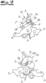
- a motor vehicle lock is shown in the figures, which is a motor vehicle door lock.
- the motor vehicle lock or motor vehicle door lock is equipped for this purpose with a locking mechanism from rotary latch 1 and pawl 2, which is in the 1 is only indicated in supervision or in the Figures 1A to 1C is reproduced only in section in the form of the pawl 2.
- an actuating lever system 3, 4, 5, 7 is provided and implemented.
- the operating lever system 3, 4, 5, 7 is composed according to the exemplary embodiment and not restrictively of an external operating lever 3, an internal operating lever 4 and a release lever 5, which are mounted coaxially with respect to a common axis 6 in a lock housing, not shown in detail.
- the actuating lever system 3, 4, 5, 7 includes a clutch lever 7, which is mounted on the release lever 5 about a further axis 8 parallel to the axis 6.
- the external activation lever 3 and the release lever 5 as well as the clutch lever 7 are primarily relevant for the following considerations. In fact, the following considerations can also be transferred to the inside actuating lever 4 .
- the external operating lever 3 is connected to an external handle, not shown, respectively an external door handle, with the aid of which the external operating lever 3 for triggering the locking mechanism 1, 2 is connected in such a way to a Figure 1A indicated force F is applied so that the external actuating lever 3 performs a clockwise movement about its axis 6, as indicated in the figures.
- the release lever 5 is able to release the pawl 2 in the illustration according to the Figures 1A to 1C to the left according to the arrow indicated, so that the pawl 2 pivots clockwise in the view of the locking mechanism 1, 2, thereby releasing the previously locked rotary latch 1.
- the rotary latch 1 then swings open with the assistance of spring force and releases a previously caught locking bolt.
- the locking mechanism 1, 2 is open. This corresponds to the "unlocked" state of the clutch lever 7, as shown in the individual illustrations according to FIG Figures 1B and 1C is shown.
- crash unit 3, 7, 9, 10, 11 ensures that the locking mechanism 1, 2 or the actuating lever mechanism 3, 4, 5 , 7 is invalidated.
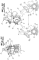
- the in the Figures 3A and 3B crash unit 3, 7, 9, 10, 11 shown in detail is based on the embodiment of an actuating lever or the External operating lever 3 and the clutch lever 7 together, which also belong to the operating lever system 3, 4, 5, 7.
- a control lever 9 to be described in more detail below is also implemented, which is set up to control the clutch lever 7 .
- the crash unit 3, 7, 9, 10, 11 also includes a mass inertia lever 10 that acts on the control lever 9.
- a component of the crash unit 3, 7, 9, 10, 11 is a spring 11, which elastically couples the actuating lever or external actuating lever 3 on the one hand and the control lever 9 on the other.
- the control lever 9 of the crash unit 3, 7, 9, 10, 11 is set up to control the clutch lever 7.
- the control lever 9 has a particular in the Figures 3A and 3B illustrated control contour 9a, 9b.
- the control contour 9a, 9b is equipped with two contour areas 9a, 9b which, according to the exemplary embodiment, enclose an obtuse angle between them, so that the control pin 7a is fixed in the area of an apex of the obtuse angle. This corresponds to the consistently occupied position "locked" of the clutch lever 7, as shown in FIG Figure 1A and the Figures 2A to 2C is shown in detail.
- a counterclockwise movement of the clutch lever 7 about its axis 8 on the release lever 5 corresponds to this to be able to
- the clutch lever 7 moves in its "unlocked” or pivoted position against the contour 3a in question, so that the actuating lever or external actuating lever 3 and the release lever 5 are mechanically connected to one another.
- Any pivoting movements of the external actuating lever 3 about its axis 6 in the indicated clockwise direction to release the locking mechanism 1, 2 are consequently transferred to the release lever 5, which is also pivoted clockwise about the common axis 6, thereby disengaging the pawl 2 from its engagement with the rotary latch 1 during the transition from the Figure 1A to the Figure 1B and on to Figure 1C can take off.
- the clutch lever 7 or its axis 8 is oriented parallel to the axis 6 of the control lever.
- the axis 6 of the control lever also acts as an axis for the release lever 5 and the actuating lever or external actuating lever 3.
- the force F acting on the external operating lever 3 by an action on an external handle for example, pivots the operating lever or external operating lever 3 in the indicated clockwise direction about its axis 6 .
- the external control lever 3 is coupled to the control lever 9 via the spring 11, a leads into the Figures 1A to 1C shown normal operation to the fact that the control lever 9 follows the clockwise movement of the external control lever 3.
- the joint pivoting movement of the actuating lever or external actuating lever 3 together with the control lever 9 in normal operation and clockwise around the common axis 6 means that the control pin 7a of the clutch lever 7 can deviate into the contour area 9a of the control lever 9, so that as a result the clutch lever 7 can be moved counterclockwise around the axis 8 to the position after the Figure 1B can swing in.
- the clutch lever 7 comes to rest on the contour 3a of the external operating lever 3 and the external operating lever 3 and the release lever 5 are consequently mechanically coupled to one another by the pivoted-in clutch lever 7 in its “unlocked” position.
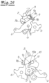
- the crash case is now in the function sequence after the Figures 2A to 2C shown.
- the actuation lever or external actuation lever 3 can now be acted upon again in the sense of opening the locking mechanism 1, 2. That is, the external operating lever 3 is in the transition from the Figure 2A to the Figure 2B again - by the deceleration forces - applied clockwise about its axis 6.
- the control lever 9 remains at rest. This is ensured by the inertia of the control lever 9, which is realized according to the exemplary embodiment through its interaction with the inertia lever 10.
- the control lever 9 can also be designed in such a way that, due to its own mass, it has the required mass inertia in order to withstand the (rapid) movements of the external activation lever 3 in the event of a crash.
- the control lever 9 maintains its position in the event of a crash by means of the mass inertia lever 10 .
- the mass inertia lever 10 is rotatably mounted about its own axis 12 .
- the control lever 9 fixes the clutch lever 7 in its “locked” position in the event of a crash. That is, the clutch lever 7 retains consistently in the event of a crash and in all functional representations after Figures 2A to 2C consistently in its "locked” position.
- the actuating lever system 3, 4, 5, 7 for triggering the locking mechanism 1, 2 is interrupted, so that the locking mechanism 1, 2 retains its closed position as desired in the event of a crash.
- the inertia lever 10 has a contour 10a for receiving a pin 9c on the control lever 9.
- the pin 9c of the control lever 9 extends predominantly perpendicularly to the planar extent of the control lever 9 and engages in the contour 10a of the inertia lever 10.
- the axis 12 of the mass inertia lever 10 runs parallel to the axes 6, 8.
- the external actuating lever 3 After the elimination of the deceleration forces, the external actuating lever 3 returns - acted upon by the spring 11 - to its original position after the Figure 2A (back again.
- the design is such that the pivoting movement of the external actuating lever 3 takes the control lever 9 with it via the spring 11 . Since the pivoting movement in normal operation is slowly below a limit speed to be determined by the dimensioning of the individual components, the interposed spring 11 ensures that the control lever 9 can follow the pivoting movements of the external actuating lever 3 .
- the mass inertia lever 10 which is also carried along during the pivoting movement via the pin 9c on the control lever 9 by engaging in the contour 10a and pivots about its axis 12 in normal operation.
- the control lever 9 can pivot in normal operation about the common axis 6 with the external control lever 3 in a clockwise direction, so that - as described - the control pin 7a on the clutch lever 7 reaches the contour area 9a of the control lever 9 and consequently into the "unlocked" position as shown in FIGS Figures 1B and 1C can swing in.
- the locking mechanism 1, 2 can consequently be opened during normal operation.
- the clutch lever 7 takes consistently in its rest position as well as in the Figures 2A to 2C the crash shown in the "locked" position. In the event of a crash, this is ensured by the control lever 9 which, according to the exemplary embodiment, builds up the required mass inertia forces in conjunction with the mass inertia lever 10 .
Landscapes
- Lock And Its Accessories (AREA)
- Mechanical Control Devices (AREA)
Claims (10)
- Serrure de véhicule automobile, en particulier serrure de portière de véhicule automobile, comportant un mécanisme de verrouillage (1, 2) constitué essentiellement d'un loquet rotatif (1) et d'un cliquet d'arrêt (2), comportant en outre un mécanisme de levier d'actionnement (3, 4, 5, 7) pour le déclenchement du mécanisme de verrouillage (1, 2) et comportant une unité d'accident (3, 7, 9, 10, 11), qui rend inefficace le mécanisme de levier d'actionnement (3, 4, 5, 7) et/ou le mécanisme de verrouillage (1, 2) au moins lorsque des forces de décélération d'une ampleur et d'une direction données se produisent, par exemple lors d'un accident (cas d'accident), dans laquelle l'unité d'accident (3, 7, 9, 10, 11) est équipée d'au moins un ressort (11), qui sollicite un levier (9), caractérisée en ce que le levier (9) est conçu comme un levier de commande (9) de l'unité d'accident (3, 7, 9, 10, 11), qui est conçu pour la commande d'un levier d'accouplement (7) du mécanisme de levier d'actionnement (3, 4, 5, 7), dans laquelle le levier d'accouplement (7) adopte en continu sa position « verrouillée » et passe dans sa position « déverrouillée » uniquement en fonctionnement normal par le biais du levier de commande (9) alors déplacé conjointement avec le mécanisme de levier d'actionnement (3, 4, 5, 7).
- Serrure de véhicule automobile selon la revendication 1,
caractérisée en ce que le levier de commande (9) et un levier d'actionnement (3) du mécanisme de levier d'actionnement (3, 4, 5, 7) sont couplés l'un à l'autre au moyen du ressort (11). - Serrure de véhicule automobile selon la revendication 1 ou 2, caractérisée en ce que le levier de commande (9) et le levier d'actionnement (3) sont montés coaxialement l'un par rapport à l'autre.
- Serrure de véhicule automobile selon l'une des revendications 1 à 3, caractérisée en ce que le levier de commande (9) présente un contour de commande (9a, 9b) pour une goupille de commande (7a) venant en prise dans le contour de commande (9a, 9b) du levier d'accouplement (7).
- Serrure de véhicule automobile selon l'une des revendications 1 à 4, caractérisée en ce que le levier d'accouplement (7) est monté rotatif autour d'un axe (8) parallèle à l'axe (6) du levier de commande (9).
- Serrure de véhicule automobile selon l'une des revendications 1 à 5, caractérisée en ce que le levier d'accouplement (7) est monté rotatif sur un levier de déclenchement (5).
- Serrure de véhicule automobile selon l'une des revendications 1 à 6, caractérisée en ce que le levier d'accouplement (7) interagit avec un contour (3a) sur le levier d'actionnement (3) de sorte que dans son état déverrouillé replié, le levier d'actionnement (3) sollicite le levier de déclenchement (5) en fonctionnement normal.
- Serrure de véhicule automobile selon l'une des revendications 1 à 7, caractérisée en ce que le levier d'accouplement (7), en cas d'accident, conserve son état verrouillé déployé par rapport au contour (3a), de sorte que le levier d'actionnement (3) est découplé du levier de commande (9) sous l'action du ressort (11).
- Serrure de véhicule automobile selon l'une des revendications 1 à 8, caractérisée en ce que le levier de commande (9), en cas d'accident, conserve sa position au moyen d'un levier d'inertie de masse (10) et le levier d'accouplement (7) est fixé dans sa position « verrouillée ».
- Serrure de véhicule automobile selon la revendication 9,
caractérisée en ce que le levier d'inertie de masse (10) présente un contour (10a) pour la réception d'une goupille (9c) du levier de commande (9).
Applications Claiming Priority (2)
| Application Number | Priority Date | Filing Date | Title |
|---|---|---|---|
| DE102019127445.1A DE102019127445A1 (de) | 2019-10-11 | 2019-10-11 | Kraftfahrzeugschloss, insbesondere Kraftfahrzeugtürschloss |
| PCT/DE2020/100868 WO2021069029A1 (fr) | 2019-10-11 | 2020-10-06 | Serrure de véhicule automobile, en particulier une serrure de portière de véhicule automobile |
Publications (2)
| Publication Number | Publication Date |
|---|---|
| EP4041971A1 EP4041971A1 (fr) | 2022-08-17 |
| EP4041971B1 true EP4041971B1 (fr) | 2023-07-26 |
Family
ID=72895881
Family Applications (1)
| Application Number | Title | Priority Date | Filing Date |
|---|---|---|---|
| EP20792524.9A Active EP4041971B1 (fr) | 2019-10-11 | 2020-10-06 | Serrure de véhicule automobile, en particulier une serrure de portière de véhicule automobile |
Country Status (4)
| Country | Link |
|---|---|
| EP (1) | EP4041971B1 (fr) |
| CN (1) | CN114555897B (fr) |
| DE (1) | DE102019127445A1 (fr) |
| WO (1) | WO2021069029A1 (fr) |
Family Cites Families (14)
| Publication number | Priority date | Publication date | Assignee | Title |
|---|---|---|---|---|
| JP5285524B2 (ja) * | 2009-07-22 | 2013-09-11 | 株式会社アンセイ | 車両用ドアロック装置 |
| DE102011010815A1 (de) * | 2011-02-09 | 2012-08-09 | Kiekert Ag | Kraftfahrzeugtürverschluss |
| DE102011010816A1 (de) * | 2011-02-09 | 2012-08-09 | Kiekert Ag | Kraftfahrzeugtürverschluss |
| DE102011100090A1 (de) | 2011-04-29 | 2012-10-31 | Kiekert Ag | Kraftfahrzeugtürverschluss |
| DE102013108293A1 (de) | 2013-08-01 | 2015-02-05 | Kiekert Aktiengesellschaft | Kraftfahrzeugtürverschluss |
| DE202013104118U1 (de) * | 2013-09-10 | 2014-12-15 | BROSE SCHLIEßSYSTEME GMBH & CO. KG | Kraftfahrzeugschloss |
| DE102013110756A1 (de) * | 2013-09-27 | 2015-04-02 | Kiekert Aktiengesellschaft | Kraftfahrzeugtürschloss |
| DE102014002581A1 (de) * | 2014-02-26 | 2015-08-27 | Kiekert Aktiengesellschaft | Kraftfahrzeugtürschloss |
| DE102014109111A1 (de) * | 2014-06-30 | 2015-12-31 | Kiekert Ag | Haubenschloss mit Steuerscheibe |
| DE102015002451A1 (de) * | 2015-02-25 | 2016-08-25 | Kiekert Aktiengesellschaft | Kraftfahrzeugtürverschluss |
| DE102016107510A1 (de) * | 2016-04-22 | 2017-10-26 | Kiekert Ag | Kraftfahrzeugtürschloss |
| DE102016121422A1 (de) * | 2016-11-09 | 2018-05-09 | Kiekert Ag | Schloss für ein Kraftfahrzeug |
| CN108729772B (zh) * | 2017-04-21 | 2019-11-29 | 开开特股份公司 | 机动车门锁 |
| DE102017127386A1 (de) * | 2017-11-21 | 2019-05-23 | Kiekert Ag | Kraftfahrzeugschloss |
-
2019
- 2019-10-11 DE DE102019127445.1A patent/DE102019127445A1/de active Pending
-
2020
- 2020-10-06 CN CN202080070932.7A patent/CN114555897B/zh active Active
- 2020-10-06 EP EP20792524.9A patent/EP4041971B1/fr active Active
- 2020-10-06 WO PCT/DE2020/100868 patent/WO2021069029A1/fr not_active Ceased
Also Published As
| Publication number | Publication date |
|---|---|
| WO2021069029A1 (fr) | 2021-04-15 |
| CN114555897A (zh) | 2022-05-27 |
| EP4041971A1 (fr) | 2022-08-17 |
| DE102019127445A1 (de) | 2021-04-15 |
| CN114555897B (zh) | 2023-08-08 |
Similar Documents
| Publication | Publication Date | Title |
|---|---|---|
| EP2673439B1 (fr) | Fermeture de portière de véhicule à moteur | |
| EP2633140B1 (fr) | Serrure de porte de véhicule automobile | |
| EP3126600B1 (fr) | Dispositif d'actionnement pour serrure de véhicule à moteur | |
| EP3445930B1 (fr) | Serrure de portière de véhicule automobile | |
| DE102011010797A1 (de) | Kraftfahrzeugtürverschluss | |
| EP3060735B1 (fr) | Serrure de portière de véhicule automobile | |
| EP3027830B1 (fr) | Serrure de portière de véhicule automobile | |
| EP2775076A2 (fr) | Dispositif de poignée extérieure de porte | |
| EP3087236B1 (fr) | Serrure de portière de véhicule automobile | |
| WO2022167031A1 (fr) | Verrou de véhicule automobile | |
| WO2020048654A1 (fr) | Ensemble poignée de porte conçu pour un véhicule automobile | |
| EP4133152B1 (fr) | Verrou de véhicule automobile | |
| EP3513021B1 (fr) | Serrure d'ouvrant de véhicule automobile | |
| EP4112851B1 (fr) | Serrure de véhicule automobile, en particulier serrure de portière de véhicule automobile | |
| EP2673438B1 (fr) | Fermeture de portière de véhicule à moteur | |
| EP4041971B1 (fr) | Serrure de véhicule automobile, en particulier une serrure de portière de véhicule automobile | |
| EP4288629B1 (fr) | Verrou de véhicule automobile | |
| DE10339542B4 (de) | Kraftfahrzeugtürverschluss | |
| DE102022121653A1 (de) | Kraftfahrzeug-Schloss | |
| WO2022171229A1 (fr) | Verrou de véhicule automobile | |
| EP4532873A1 (fr) | Serrure de véhicule automobile | |
| DE102023125174A1 (de) | Kraftfahrzeugschloss für ein Verschlusselement eines Kraftfahrzeugs | |
| DE102024118172A1 (de) | Kraftfahrzeug-Schloss | |
| DE102019135228A1 (de) | Kraftfahrzeug-Schloss, insbesondere Kraftfahrzeug-Türschloss |
Legal Events
| Date | Code | Title | Description |
|---|---|---|---|
| STAA | Information on the status of an ep patent application or granted ep patent |
Free format text: STATUS: UNKNOWN |
|
| STAA | Information on the status of an ep patent application or granted ep patent |
Free format text: STATUS: THE INTERNATIONAL PUBLICATION HAS BEEN MADE |
|
| PUAI | Public reference made under article 153(3) epc to a published international application that has entered the european phase |
Free format text: ORIGINAL CODE: 0009012 |
|
| STAA | Information on the status of an ep patent application or granted ep patent |
Free format text: STATUS: REQUEST FOR EXAMINATION WAS MADE |
|
| 17P | Request for examination filed |
Effective date: 20220401 |
|
| AK | Designated contracting states |
Kind code of ref document: A1 Designated state(s): AL AT BE BG CH CY CZ DE DK EE ES FI FR GB GR HR HU IE IS IT LI LT LU LV MC MK MT NL NO PL PT RO RS SE SI SK SM TR |
|
| DAV | Request for validation of the european patent (deleted) | ||
| DAX | Request for extension of the european patent (deleted) | ||
| GRAP | Despatch of communication of intention to grant a patent |
Free format text: ORIGINAL CODE: EPIDOSNIGR1 |
|
| STAA | Information on the status of an ep patent application or granted ep patent |
Free format text: STATUS: GRANT OF PATENT IS INTENDED |
|
| INTG | Intention to grant announced |
Effective date: 20230510 |
|
| GRAS | Grant fee paid |
Free format text: ORIGINAL CODE: EPIDOSNIGR3 |
|
| GRAA | (expected) grant |
Free format text: ORIGINAL CODE: 0009210 |
|
| STAA | Information on the status of an ep patent application or granted ep patent |
Free format text: STATUS: THE PATENT HAS BEEN GRANTED |
|
| AK | Designated contracting states |
Kind code of ref document: B1 Designated state(s): AL AT BE BG CH CY CZ DE DK EE ES FI FR GB GR HR HU IE IS IT LI LT LU LV MC MK MT NL NO PL PT RO RS SE SI SK SM TR |
|
| REG | Reference to a national code |
Ref country code: CH Ref legal event code: EP |
|
| REG | Reference to a national code |
Ref country code: DE Ref legal event code: R096 Ref document number: 502020004418 Country of ref document: DE |
|
| REG | Reference to a national code |
Ref country code: IE Ref legal event code: FG4D Free format text: LANGUAGE OF EP DOCUMENT: GERMAN |
|
| REG | Reference to a national code |
Ref country code: LT Ref legal event code: MG9D |
|
| REG | Reference to a national code |
Ref country code: NL Ref legal event code: MP Effective date: 20230726 |
|
| PG25 | Lapsed in a contracting state [announced via postgrant information from national office to epo] |
Ref country code: NL Free format text: LAPSE BECAUSE OF FAILURE TO SUBMIT A TRANSLATION OF THE DESCRIPTION OR TO PAY THE FEE WITHIN THE PRESCRIBED TIME-LIMIT Effective date: 20230726 |
|
| PG25 | Lapsed in a contracting state [announced via postgrant information from national office to epo] |
Ref country code: GR Free format text: LAPSE BECAUSE OF FAILURE TO SUBMIT A TRANSLATION OF THE DESCRIPTION OR TO PAY THE FEE WITHIN THE PRESCRIBED TIME-LIMIT Effective date: 20231027 |
|
| PG25 | Lapsed in a contracting state [announced via postgrant information from national office to epo] |
Ref country code: IS Free format text: LAPSE BECAUSE OF FAILURE TO SUBMIT A TRANSLATION OF THE DESCRIPTION OR TO PAY THE FEE WITHIN THE PRESCRIBED TIME-LIMIT Effective date: 20231126 |
|
| PG25 | Lapsed in a contracting state [announced via postgrant information from national office to epo] |
Ref country code: SE Free format text: LAPSE BECAUSE OF FAILURE TO SUBMIT A TRANSLATION OF THE DESCRIPTION OR TO PAY THE FEE WITHIN THE PRESCRIBED TIME-LIMIT Effective date: 20230726 Ref country code: RS Free format text: LAPSE BECAUSE OF FAILURE TO SUBMIT A TRANSLATION OF THE DESCRIPTION OR TO PAY THE FEE WITHIN THE PRESCRIBED TIME-LIMIT Effective date: 20230726 Ref country code: PT Free format text: LAPSE BECAUSE OF FAILURE TO SUBMIT A TRANSLATION OF THE DESCRIPTION OR TO PAY THE FEE WITHIN THE PRESCRIBED TIME-LIMIT Effective date: 20231127 Ref country code: NO Free format text: LAPSE BECAUSE OF FAILURE TO SUBMIT A TRANSLATION OF THE DESCRIPTION OR TO PAY THE FEE WITHIN THE PRESCRIBED TIME-LIMIT Effective date: 20231026 Ref country code: LV Free format text: LAPSE BECAUSE OF FAILURE TO SUBMIT A TRANSLATION OF THE DESCRIPTION OR TO PAY THE FEE WITHIN THE PRESCRIBED TIME-LIMIT Effective date: 20230726 Ref country code: LT Free format text: LAPSE BECAUSE OF FAILURE TO SUBMIT A TRANSLATION OF THE DESCRIPTION OR TO PAY THE FEE WITHIN THE PRESCRIBED TIME-LIMIT Effective date: 20230726 Ref country code: IS Free format text: LAPSE BECAUSE OF FAILURE TO SUBMIT A TRANSLATION OF THE DESCRIPTION OR TO PAY THE FEE WITHIN THE PRESCRIBED TIME-LIMIT Effective date: 20231126 Ref country code: HR Free format text: LAPSE BECAUSE OF FAILURE TO SUBMIT A TRANSLATION OF THE DESCRIPTION OR TO PAY THE FEE WITHIN THE PRESCRIBED TIME-LIMIT Effective date: 20230726 Ref country code: GR Free format text: LAPSE BECAUSE OF FAILURE TO SUBMIT A TRANSLATION OF THE DESCRIPTION OR TO PAY THE FEE WITHIN THE PRESCRIBED TIME-LIMIT Effective date: 20231027 Ref country code: FI Free format text: LAPSE BECAUSE OF FAILURE TO SUBMIT A TRANSLATION OF THE DESCRIPTION OR TO PAY THE FEE WITHIN THE PRESCRIBED TIME-LIMIT Effective date: 20230726 |
|
| PG25 | Lapsed in a contracting state [announced via postgrant information from national office to epo] |
Ref country code: PL Free format text: LAPSE BECAUSE OF FAILURE TO SUBMIT A TRANSLATION OF THE DESCRIPTION OR TO PAY THE FEE WITHIN THE PRESCRIBED TIME-LIMIT Effective date: 20230726 |
|
| PG25 | Lapsed in a contracting state [announced via postgrant information from national office to epo] |
Ref country code: ES Free format text: LAPSE BECAUSE OF FAILURE TO SUBMIT A TRANSLATION OF THE DESCRIPTION OR TO PAY THE FEE WITHIN THE PRESCRIBED TIME-LIMIT Effective date: 20230726 |
|
| REG | Reference to a national code |
Ref country code: DE Ref legal event code: R097 Ref document number: 502020004418 Country of ref document: DE |
|
| PG25 | Lapsed in a contracting state [announced via postgrant information from national office to epo] |
Ref country code: SM Free format text: LAPSE BECAUSE OF FAILURE TO SUBMIT A TRANSLATION OF THE DESCRIPTION OR TO PAY THE FEE WITHIN THE PRESCRIBED TIME-LIMIT Effective date: 20230726 Ref country code: RO Free format text: LAPSE BECAUSE OF FAILURE TO SUBMIT A TRANSLATION OF THE DESCRIPTION OR TO PAY THE FEE WITHIN THE PRESCRIBED TIME-LIMIT Effective date: 20230726 Ref country code: ES Free format text: LAPSE BECAUSE OF FAILURE TO SUBMIT A TRANSLATION OF THE DESCRIPTION OR TO PAY THE FEE WITHIN THE PRESCRIBED TIME-LIMIT Effective date: 20230726 Ref country code: EE Free format text: LAPSE BECAUSE OF FAILURE TO SUBMIT A TRANSLATION OF THE DESCRIPTION OR TO PAY THE FEE WITHIN THE PRESCRIBED TIME-LIMIT Effective date: 20230726 Ref country code: DK Free format text: LAPSE BECAUSE OF FAILURE TO SUBMIT A TRANSLATION OF THE DESCRIPTION OR TO PAY THE FEE WITHIN THE PRESCRIBED TIME-LIMIT Effective date: 20230726 Ref country code: SK Free format text: LAPSE BECAUSE OF FAILURE TO SUBMIT A TRANSLATION OF THE DESCRIPTION OR TO PAY THE FEE WITHIN THE PRESCRIBED TIME-LIMIT Effective date: 20230726 |
|
| P01 | Opt-out of the competence of the unified patent court (upc) registered |
Effective date: 20240404 |
|
| PG25 | Lapsed in a contracting state [announced via postgrant information from national office to epo] |
Ref country code: IT Free format text: LAPSE BECAUSE OF FAILURE TO SUBMIT A TRANSLATION OF THE DESCRIPTION OR TO PAY THE FEE WITHIN THE PRESCRIBED TIME-LIMIT Effective date: 20230726 Ref country code: MC Free format text: LAPSE BECAUSE OF FAILURE TO SUBMIT A TRANSLATION OF THE DESCRIPTION OR TO PAY THE FEE WITHIN THE PRESCRIBED TIME-LIMIT Effective date: 20230726 |
|
| PLBE | No opposition filed within time limit |
Free format text: ORIGINAL CODE: 0009261 |
|
| REG | Reference to a national code |
Ref country code: CH Ref legal event code: PL |
|
| STAA | Information on the status of an ep patent application or granted ep patent |
Free format text: STATUS: NO OPPOSITION FILED WITHIN TIME LIMIT |
|
| REG | Reference to a national code |
Ref country code: BE Ref legal event code: MM Effective date: 20231031 |
|
| PG25 | Lapsed in a contracting state [announced via postgrant information from national office to epo] |
Ref country code: LU Free format text: LAPSE BECAUSE OF NON-PAYMENT OF DUE FEES Effective date: 20231006 |
|
| PG25 | Lapsed in a contracting state [announced via postgrant information from national office to epo] |
Ref country code: LU Free format text: LAPSE BECAUSE OF NON-PAYMENT OF DUE FEES Effective date: 20231006 |
|
| 26N | No opposition filed |
Effective date: 20240429 |
|
| PG25 | Lapsed in a contracting state [announced via postgrant information from national office to epo] |
Ref country code: CH Free format text: LAPSE BECAUSE OF NON-PAYMENT OF DUE FEES Effective date: 20231031 |
|
| PG25 | Lapsed in a contracting state [announced via postgrant information from national office to epo] |
Ref country code: CH Free format text: LAPSE BECAUSE OF NON-PAYMENT OF DUE FEES Effective date: 20231031 Ref country code: SI Free format text: LAPSE BECAUSE OF FAILURE TO SUBMIT A TRANSLATION OF THE DESCRIPTION OR TO PAY THE FEE WITHIN THE PRESCRIBED TIME-LIMIT Effective date: 20230726 |
|
| PG25 | Lapsed in a contracting state [announced via postgrant information from national office to epo] |
Ref country code: BE Free format text: LAPSE BECAUSE OF NON-PAYMENT OF DUE FEES Effective date: 20231031 |
|
| PG25 | Lapsed in a contracting state [announced via postgrant information from national office to epo] |
Ref country code: IE Free format text: LAPSE BECAUSE OF NON-PAYMENT OF DUE FEES Effective date: 20231006 |
|
| PG25 | Lapsed in a contracting state [announced via postgrant information from national office to epo] |
Ref country code: IE Free format text: LAPSE BECAUSE OF NON-PAYMENT OF DUE FEES Effective date: 20231006 |
|
| PG25 | Lapsed in a contracting state [announced via postgrant information from national office to epo] |
Ref country code: BG Free format text: LAPSE BECAUSE OF FAILURE TO SUBMIT A TRANSLATION OF THE DESCRIPTION OR TO PAY THE FEE WITHIN THE PRESCRIBED TIME-LIMIT Effective date: 20230726 |
|
| PG25 | Lapsed in a contracting state [announced via postgrant information from national office to epo] |
Ref country code: BG Free format text: LAPSE BECAUSE OF FAILURE TO SUBMIT A TRANSLATION OF THE DESCRIPTION OR TO PAY THE FEE WITHIN THE PRESCRIBED TIME-LIMIT Effective date: 20230726 |
|
| GBPC | Gb: european patent ceased through non-payment of renewal fee |
Effective date: 20241006 |
|
| PG25 | Lapsed in a contracting state [announced via postgrant information from national office to epo] |
Ref country code: GB Free format text: LAPSE BECAUSE OF NON-PAYMENT OF DUE FEES Effective date: 20241006 |
|
| PG25 | Lapsed in a contracting state [announced via postgrant information from national office to epo] |
Ref country code: CY Free format text: LAPSE BECAUSE OF FAILURE TO SUBMIT A TRANSLATION OF THE DESCRIPTION OR TO PAY THE FEE WITHIN THE PRESCRIBED TIME-LIMIT; INVALID AB INITIO Effective date: 20201006 |
|
| PG25 | Lapsed in a contracting state [announced via postgrant information from national office to epo] |
Ref country code: HU Free format text: LAPSE BECAUSE OF FAILURE TO SUBMIT A TRANSLATION OF THE DESCRIPTION OR TO PAY THE FEE WITHIN THE PRESCRIBED TIME-LIMIT; INVALID AB INITIO Effective date: 20201006 |
|
| PGFP | Annual fee paid to national office [announced via postgrant information from national office to epo] |
Ref country code: CZ Payment date: 20250923 Year of fee payment: 6 |
|
| PG25 | Lapsed in a contracting state [announced via postgrant information from national office to epo] |
Ref country code: TR Free format text: LAPSE BECAUSE OF FAILURE TO SUBMIT A TRANSLATION OF THE DESCRIPTION OR TO PAY THE FEE WITHIN THE PRESCRIBED TIME-LIMIT Effective date: 20230726 |
|
| PGFP | Annual fee paid to national office [announced via postgrant information from national office to epo] |
Ref country code: AT Payment date: 20260113 Year of fee payment: 5 |
|
| PGFP | Annual fee paid to national office [announced via postgrant information from national office to epo] |
Ref country code: DE Payment date: 20260326 Year of fee payment: 6 |
|
| PGFP | Annual fee paid to national office [announced via postgrant information from national office to epo] |
Ref country code: FR Payment date: 20260330 Year of fee payment: 6 |