EP4042007B1 - Apparatus, method and computer program for monitoring an aircraft engine - Google Patents
Apparatus, method and computer program for monitoring an aircraft engine Download PDFInfo
- Publication number
- EP4042007B1 EP4042007B1 EP20796633.4A EP20796633A EP4042007B1 EP 4042007 B1 EP4042007 B1 EP 4042007B1 EP 20796633 A EP20796633 A EP 20796633A EP 4042007 B1 EP4042007 B1 EP 4042007B1
- Authority
- EP
- European Patent Office
- Prior art keywords
- engine
- flight
- variables
- values
- env
- Prior art date
- Legal status (The legal status is an assumption and is not a legal conclusion. Google has not performed a legal analysis and makes no representation as to the accuracy of the status listed.)
- Active
Links
Images



Classifications
-
- B—PERFORMING OPERATIONS; TRANSPORTING
- B64—AIRCRAFT; AVIATION; COSMONAUTICS
- B64D—EQUIPMENT FOR FITTING IN OR TO AIRCRAFT; FLIGHT SUITS; PARACHUTES; ARRANGEMENT OR MOUNTING OF POWER PLANTS OR PROPULSION TRANSMISSIONS IN AIRCRAFT
- B64D45/00—Aircraft indicators or protectors not otherwise provided for
-
- F—MECHANICAL ENGINEERING; LIGHTING; HEATING; WEAPONS; BLASTING
- F02—COMBUSTION ENGINES; HOT-GAS OR COMBUSTION-PRODUCT ENGINE PLANTS
- F02C—GAS-TURBINE PLANTS; AIR INTAKES FOR JET-PROPULSION PLANTS; CONTROLLING FUEL SUPPLY IN AIR-BREATHING JET-PROPULSION PLANTS
- F02C9/00—Controlling gas-turbine plants; Controlling fuel supply in air- breathing jet-propulsion plants
-
- G—PHYSICS
- G05—CONTROLLING; REGULATING
- G05B—CONTROL OR REGULATING SYSTEMS IN GENERAL; FUNCTIONAL ELEMENTS OF SUCH SYSTEMS; MONITORING OR TESTING ARRANGEMENTS FOR SUCH SYSTEMS OR ELEMENTS
- G05B23/00—Testing or monitoring of control systems or parts thereof
- G05B23/02—Electric testing or monitoring
- G05B23/0205—Electric testing or monitoring by means of a monitoring system capable of detecting and responding to faults
- G05B23/0218—Electric testing or monitoring by means of a monitoring system capable of detecting and responding to faults characterised by the fault detection method dealing with either existing or incipient faults
- G05B23/0243—Electric testing or monitoring by means of a monitoring system capable of detecting and responding to faults characterised by the fault detection method dealing with either existing or incipient faults model based detection method, e.g. first-principles knowledge model
- G05B23/0254—Electric testing or monitoring by means of a monitoring system capable of detecting and responding to faults characterised by the fault detection method dealing with either existing or incipient faults model based detection method, e.g. first-principles knowledge model based on a quantitative model, e.g. mathematical relationships between inputs and outputs; functions: observer, Kalman filter, residual calculation, Neural Networks
-
- B—PERFORMING OPERATIONS; TRANSPORTING
- B64—AIRCRAFT; AVIATION; COSMONAUTICS
- B64D—EQUIPMENT FOR FITTING IN OR TO AIRCRAFT; FLIGHT SUITS; PARACHUTES; ARRANGEMENT OR MOUNTING OF POWER PLANTS OR PROPULSION TRANSMISSIONS IN AIRCRAFT
- B64D45/00—Aircraft indicators or protectors not otherwise provided for
- B64D2045/0085—Devices for aircraft health monitoring, e.g. monitoring flutter or vibration
-
- F—MECHANICAL ENGINEERING; LIGHTING; HEATING; WEAPONS; BLASTING
- F05—INDEXING SCHEMES RELATING TO ENGINES OR PUMPS IN VARIOUS SUBCLASSES OF CLASSES F01-F04
- F05D—INDEXING SCHEME FOR ASPECTS RELATING TO NON-POSITIVE-DISPLACEMENT MACHINES OR ENGINES, GAS-TURBINES OR JET-PROPULSION PLANTS
- F05D2270/00—Control
- F05D2270/40—Type of control system
- F05D2270/44—Type of control system active, predictive, or anticipative
-
- F—MECHANICAL ENGINEERING; LIGHTING; HEATING; WEAPONS; BLASTING
- F05—INDEXING SCHEMES RELATING TO ENGINES OR PUMPS IN VARIOUS SUBCLASSES OF CLASSES F01-F04
- F05D—INDEXING SCHEME FOR ASPECTS RELATING TO NON-POSITIVE-DISPLACEMENT MACHINES OR ENGINES, GAS-TURBINES OR JET-PROPULSION PLANTS
- F05D2270/00—Control
- F05D2270/70—Type of control algorithm
- F05D2270/71—Type of control algorithm synthesized, i.e. parameter computed by a mathematical model
-
- G—PHYSICS
- G05—CONTROLLING; REGULATING
- G05B—CONTROL OR REGULATING SYSTEMS IN GENERAL; FUNCTIONAL ELEMENTS OF SUCH SYSTEMS; MONITORING OR TESTING ARRANGEMENTS FOR SUCH SYSTEMS OR ELEMENTS
- G05B2219/00—Program-control systems
- G05B2219/30—Nc systems
- G05B2219/45—Nc applications
- G05B2219/45071—Aircraft, airplane, ship cleaning manipulator, paint stripping
Definitions
- the invention relates to a device, a method and a computer program for temporal monitoring of the state of at least one propulsion engine of at least one aircraft.
- aircraft such as airplanes and helicopters, where engines, which may be turbomachines, are monitored.
- the document US 2017/185937A1 relates to a system for evaluating flight data of an aircraft, a system calculating for each flight estimates of the values of variables obtained by applying a learning model to acquired observation data.
- the document US 8,600,917 describes a method and apparatus for monitoring wear in an aircraft engine, having an engine flight data collection component, using an output model to provide a prediction of a parameter based on values of other parameters, and calculating residuals, representing the respective differences between each measurement of the parameter and each corresponding prediction of the parameter.
- the document US 2017/352204A1 relates to a system for predicting failures on an aircraft, having an analysis of the current behavior of a flight parameter to detect any deviation from a model of this parameter, having been pre-constructed in a preliminary learning phase from series of training data concerning the parameter, collected during flights of a set of aircraft.
- the document US 2018/170580A1 relates to a method of monitoring an aircraft, providing for calculating by a regression model, a standardized value of an endogenous parameter in relation to an exogenous parameter specific to the environment.
- a problem arising on aircraft engines is that the transfer function may change over time locally and the available data may not cover the entire flight envelope.
- the flight often does not cover the entire operating range of the engine, and the use of a global model and a comparison with the measured variables is not sufficient to monitor the engine.
- Modeling parameter tracking is not robust to changes in the flight envelope, because the parameters can change without the engine state being affected.
- the residuals or the values of the variables can also be affected by changes in the environment or inputs.
- the state-of-the-art solutions are not robust to external conditions. In the event of absence of data or little data on a part of the flight envelope, it is possible that the residuals or the parameters, estimated on data that is too far away, do not allow the change in the transfer function to be detected.
- the invention aims to obtain a device, a method and a computer program for the temporal monitoring of the state of at least one propulsion engine of at least one aircraft, which makes it possible to solve the problem set out above.
- the invention there is no need to have a parametric model or a global existing model. If the phenomenon to be detected covers a part of the variable space that is not or only slightly covered during the flight analyzed, it is still possible to observe it by applying the individual flight models to the reference values.
- the invention thus makes it possible to detect changes in the transfer function of the monitored engine that would not have been detected, and also makes it possible to avoid false alarms.
- the advantage of the invention compared to the state of the art is to be able to compare flights that do not have the same distribution of variables. The invention avoids making an interpretation error when comparing the models in two different domains. The invention makes it possible to compare in the same domain.
- the device comprises at least one physical output for presenting information to a user, for providing engine tracking information for the flight which is determined by the user module at least from the estimates of values of the engine output variables and from the error associated with these estimates and with the individual flight model.
- the engine tracking information for the flight is formed by the pair consisting of the estimates of the values of the engine output variables and the error associated with the estimates and the individual flight model.
- the learning module is configured to calculate by learning from the data of each flight, an estimate of modeling error of the individual flight model on the engine output variables, the error associated with the individual flight model comprising said individual flight model modeling error estimate.
- At least some of the reference values of the engine reference input variables and/or the reference values of the engine environment variables and/or the reference values of the engine output variables are prescribed in association with each other in the prescribed set of reference data.
- At least some of the reference values of the engine reference input variables and/or the reference values of the engine environment variables and/or the reference values of the Engine output variables are flight data that have been obtained by the acquisition module for at least one flight performed.
- At least some of the reference values of the engine reference input variables and/or the reference values of the engine environmental variables and/or the reference values of the engine output variables are simulated flight data for at least one unperformed flight.
- a second subject of the invention is a computer program comprising code instructions for implementing the method for temporally monitoring the state of at least one propulsion engine of at least one aircraft as described above, when it is implemented on a computer of the aircraft.
- E1 i , ENV1 i and S1 i are acquired during the flight V i and are associated with each other for each flight V i considered.
- the ACQ acquisition module may be partially or completely embedded on the engine(s) M of the aircraft or on the aircraft.
- the aircraft may be, for example, an airplane or a helicopter.
- the propulsion engine M of the aircraft may be a turbomachine, such as, for example, a turbojet, or others.
- the ACQ acquisition module may comprise first CE sensors for measuring the values E1 i of the input variables E of the engine during the flight V i , and/or second CENV sensors for measuring the values ENV1 i of the environmental variables ENV of the engine M during the flight V i and/or third CS sensors for measuring the values S1 i of the output variables S of the engine M during the flight V i .
- the engine input variables E are control variables on which commands from the aircraft pilot can act to control the engine.
- the engine input variables E may include, for example, a rotational speed of the engine M and/or a pilot command sent to the engine M and/or a control torque of the engine M and/or others.
- the environment variables ENV of the engine M are variables external to the engine M and non-controllable, and may include, for example, an external temperature and/or an external pressure and/or a humidity level and/or a presence of pollution and/or others.
- the output variables S of the engine M are variables resulting from the input variables E and the environment variables ENV and may include, for example, a temperature of the engine M and/or a rotational torque of the rotor of the engine M and/or an instantaneous fuel consumption of the engine M and/or others.
- the acquisition ACQ module can for example record in a memory on board the aircraft, for example in its on-board computer or in a box on board the aircraft, the data DV i of flights V i comprising the values E1 i , ENV1 i and S1 i mentioned above.
- the data DV i of flights V i can be extracted from the ground memory after each flight V i to be sent to the other modules described below of the tracking device 1.
- the tracking device 1 comprises a learning APPR module for generating an individual flight model f i for each flight V i .
- the learning APPR module thus makes it possible to calculate several individual flight models f i for several successive flights V i , V i+1 over time t.
- the index i relates to the flight V i and therefore to the time.
- the learning APPR module is configured to calculate by learning from the data DV i , E1 i , ENV1 i and S1 i of each flight V i the individual flight model f i , linking for this flight V i the input variables E of the engine M, the environment variables ENV of the engine M and the output variables S of the engine M.
- the data DV i , E1 i , ENV1 i and S1 i are learning data of the model f i .
- the model learning APPR module learns the model f i which links the inputs E, the flight ENV variables and the outputs S thanks to the newly acquired data and possibly a part of the past data.
- the part of the past data can be determined by a sliding window in time, or any other device weighting the different data of the previous flights.
- the first values E1 i , ENV1 i , S i of engine input variables E, engine environment variables ENV and engine output variables S are a training data set of the individual flight model f i .
- models f i may be used only on the reference variables, ENV R and E R .
- the tracking device 1 includes a MUT module for using the individual flight models V i , having been calculated by the APPR learning module.
- the reference E R , ENV R values belong to a prescribed set of reference DR data and which are identical for the plurality i of individual flight models f i V i .
- the MUT usage module comprises an ACC access for prescribing or entering the reference DR data.
- the MUT module for using the model f i applies the model f i to a reference DR set of data (flight ENV R variables, input E R variables).
- This reference DR set can be previously stored data, or simulated data.
- This fixed reference DR set can be one or more past flights, or one or more simulated flights, or finally one or more specific points in the validity space of the learned model f i .
- the MUT model use module has as inputs the model f i and the reference DR data and as output estimates of physical quantities.
- the reference DR set makes it possible to compare several learned models f i under different conditions.
- the individual flight model V i uses an algorithm that can be any regression algorithm such as a linear regression, or a Gaussian process, or a linear Gaussian process regression, or a random forest, or a neural network, or a regression by the least squares method or a polynomial regression of order greater than or equal to 2, this algorithm linking the calculated values of the output variables S of the engine M to the values of the input variables E of the engine M and to the environment variables ENV of the engine M.
- the MUT module estimates the reliability of the model, in comparing the training set and the reference DR set, and/or using the training error.
- a possible example of implementation is the use of a regression method providing such an estimate, such as Gaussian processes or any other probabilistic method.
- Another possibility is to use the distance between the two sets, such as the Chamfer distance.
- any estimation technique such as testing the model on a data set not used during training (this set is often called a validation set in the state of the art).
- the individual flight model V i can link the calculated values of the output variables S of the engine M to the values of the input variables E of the engine M and to the environment variables ENV of the engine M.
- the MUT usage module is configured to also calculate, for each flight V i , an error ⁇ i associated with the output value estimates S calculated by the individual flight model f i V i . This error ⁇ i is therefore calculated by the MUT usage module from the individual flight model f i V i .
- the MUT module of use is configured to monitor whether the second values S2 i increase then decrease between flights V i-1 , V i , V i+1 and whether the associated error ⁇ i remains low (the associated error ⁇ i remains below a prescribed threshold), in order to, in the affirmative, on both these conditions, automatically trigger an alarm on one or more physical outputs SP for presenting information to a user (display screen and/or others), this alarm indicating that there is a problem on the engine M monitored or on the aircraft having this engine M monitored.
- the tracking device and method according to the invention can make it possible to compare the different models f i with each other, using the models f i on the reference set.
- the tracking device 1 may comprise one or more physical outputs SP for presenting information to a user (display screen and/or others), to provide the engine tracking information INF for the flight Vi.
- this information INF is the torque (S2 i , ⁇ i ).
- the device 1 may comprise a module for automatic tracking of breaks, trends and anomalies in the torque (S2 i , ⁇ i ), implemented by a computer and having as inputs the estimates of physical quantities and the estimates of errors, and as outputs: information INF signaling breaks and/or trends and/or anomalies.
- the user may also use a visual approach, to notice trends, anomalies and breaks, or any automatic algorithm for tracking time series, implemented by a computer.
- a maintenance operation or advice on the use of the monitored M engine may be issued to the customer operating the monitored M engine and/or the aircraft.
- This distance d(E R , E1 i ) can be a distance between sets of points, for example a Hausdorff distance.
- this error ⁇ i can be calculated by assuming that the first values ENV1 i of the environment ENV variables are the same for the different values E1 i and S1 i .
- the individual flight model V i can be a linear regression relating the second output values S2 i to the first values E R , ENV R and relating the third output values S3 i to the first values E1 i , ENV1 i .
- the APPR learning module is configured to calculate by learning, from the first data DV i of each flight V i , an estimate EM of modeling error of the individual flight model f i on the output variables S of the engine M.
- At least some (or all) of the reference E R values and/or at least some (or all) of the reference ENV R values and/or at least some (or all) of the reference S R values are prescribed in association with each other in the prescribed set of reference DR data.
- At least some (or all) of the reference E R values and/or at least some (or all) of the reference ENV R values and/or at least some (or all) of the reference S R values are first flight DV data having been obtained by the acquisition ACQ module for at least one flight V i performed.
- the reference flight(s) V R may be one or more flights V i performed.
- At least some (or all) of the reference E R values and/or at least some (or all) of the reference ENV R values and/or at least some (or all) of the reference S R values are first flight DV data having been simulated for at least one flight V i not actually performed by the aircraft.
- the reference flight(s) V R may be one or more simulated flights V i not actually performed by the aircraft.
- the tracking device 1 makes it possible to implement a method for temporally tracking the state of at least one propulsion engine M of at least one aircraft A, which comprises the steps described below with reference to the figure 6 . These steps are performed automatically by the tracking device 1.
- the DV i data described above are acquired by the ACQ acquisition module.
- the individual flight model f i described above is calculated by the APPR learning module.
- the tracking method may implement one and/or the other of the embodiments described above.
- the tracking device 1 and its APPR, MUT, MTF modules can be implemented by one or more calculators, such as for example one or more computers, or other calculation means.
- the tracking device 1 can comprise a computer program, recorded in a permanent memory thereof, to implement the APPR, MUT, MTF modules and to execute the steps of the tracking method.
Landscapes
- Engineering & Computer Science (AREA)
- Physics & Mathematics (AREA)
- Combustion & Propulsion (AREA)
- Chemical & Material Sciences (AREA)
- Mathematical Physics (AREA)
- General Physics & Mathematics (AREA)
- Automation & Control Theory (AREA)
- Evolutionary Computation (AREA)
- Artificial Intelligence (AREA)
- Mechanical Engineering (AREA)
- General Engineering & Computer Science (AREA)
- Aviation & Aerospace Engineering (AREA)
- Combined Controls Of Internal Combustion Engines (AREA)
- Testing And Monitoring For Control Systems (AREA)
- Testing Of Engines (AREA)
- Management, Administration, Business Operations System, And Electronic Commerce (AREA)
Description
L'invention concerne un dispositif, un procédé et un programme d'ordinateur pour le suivi temporel de l'état d'au moins un moteur de propulsion d'au moins un aéronef.The invention relates to a device, a method and a computer program for temporal monitoring of the state of at least one propulsion engine of at least one aircraft.
Un domaine d'application concerne les aéronefs tels que les avions et les hélicoptères, dont on surveille les moteurs pouvant être des turbomachines.One area of application is aircraft such as airplanes and helicopters, where engines, which may be turbomachines, are monitored.
Le document
Le document
Le document
Le document
Un problème apparaissant sur les moteurs d'aéronefs, est que la fonction de transfert peut changer au cours du temps localement et que les données disponibles peuvent ne pas couvrir la totalité du domaine de vol.A problem arising on aircraft engines is that the transfer function may change over time locally and the available data may not cover the entire flight envelope.
Dans l'état de la technique, bien souvent le vol ne couvre pas tout le domaine de fonctionnement du moteur, et l'utilisation d'un modèle global et d'une comparaison avec les variables mesurées ne suffit pas pour suivre le moteur.In the state of the art, the flight often does not cover the entire operating range of the engine, and the use of a global model and a comparison with the measured variables is not sufficient to monitor the engine.
En effet, si une modification de la fonction de transfert survient dans des zones peu ou pas explorées du domaine de vol, il est alors difficile de l'observer par la comparaison, du fait que les différences sont noyées dans le bruit, ou ne peuvent pas être observées. L'état de la technique consiste en différentes méthodes, que sont le suivi de paramètres de modélisation, le suivi de résidu, ou le suivi de valeurs de variables. Le suivi de paramètres de modélisation n'est pas robuste aux changements de domaine de vol, car les paramètres peuvent changer sans que l'état moteur soit affecté. Les résidus ou bien les valeurs des variables peuvent également être affectés par des changements de l'environnement ou des entrées. Ainsi, les solutions de l'état de la technique ne sont pas robustes aux conditions extérieures. En cas d'absence de données ou de peu de données sur une partie du domaine de vol, il est possible que les résidus ou les paramètres, estimés sur des données trop éloignées, ne permettent pas de détecter le changement de fonction de transfert.Indeed, if a change in the transfer function occurs in little or unexplored areas of the flight envelope, it is then difficult to observe it by comparison, because the differences are drowned in noise, or cannot be observed. The state of the art consists of different methods, which are modeling parameter tracking, residual tracking, or variable value tracking. Modeling parameter tracking is not robust to changes in the flight envelope, because the parameters can change without the engine state being affected. The residuals or the values of the variables can also be affected by changes in the environment or inputs. Thus, the state-of-the-art solutions are not robust to external conditions. In the event of absence of data or little data on a part of the flight envelope, it is possible that the residuals or the parameters, estimated on data that is too far away, do not allow the change in the transfer function to be detected.
L'invention vise à obtenir un dispositif, un procédé et un programme d'ordinateur pour le suivi temporel de l'état d'au moins un moteur de propulsion d'au moins un aéronef, qui permette de résoudre le problème exposé ci-dessus.The invention aims to obtain a device, a method and a computer program for the temporal monitoring of the state of at least one propulsion engine of at least one aircraft, which makes it possible to solve the problem set out above.
A cet effet, un premier objet de l'invention est un dispositif de suivi temporel de l'état d'au moins un moteur de propulsion d'au moins un aéronef, caractérisé en ce que le dispositif comporte
- un module d'acquisition de données de vols du au moins un moteur de propulsion du au moins un aéronef, comportant en association pour chaque vol des valeurs de variables d'entrée du moteur lors du vol, des valeurs de variables d'environnement du moteur lors du vol et des valeurs de variables de sortie du moteur lors du vol,
- un module d'apprentissage configuré pour calculer par apprentissage à partir des données de chaque vol un modèle individuel de vol pour le vol, liant les variables d'entrée du moteur, les variables d'environnement du moteur et les variables de sortie du moteur,
- un module d'utilisation des modèles individuels de vol, configuré pour calculer, pour chaque vol:
- des estimations des valeurs des variables de sortie du moteur, qui sont obtenues en appliquant le modèle individuel de vol à des valeurs de référence des variables d'entrée du moteur et à des valeurs de référence des variables d'environnement du moteur, et
- une erreur associée auxdites estimations des valeurs des variables de sortie du moteur, qui ont générées par le modèle individuel de vol et qui ont été obtenues en appliquant le modèle (fi) individuel de vol (Vi) aux valeurs (ER) de référence des variables (E) d'entrée du moteur (M) et aux valeurs (ENVR) de référence des variables (ENV) d'environnement du moteur (M),
- les valeurs de référence appartenant à un ensemble prescrit de données de référence, qui sont identiques pour la pluralité des modèles individuels de vol.
- a flight data acquisition module for at least one propulsion engine of at least one aircraft, comprising in association for each flight values of input variables of the engine during the flight, values of environmental variables of the engine during the flight and values of output variables of the engine during the flight,
- a learning module configured to calculate by learning from the data of each flight an individual flight model for the flight, linking the engine input variables, the engine environmental variables and the engine output variables,
- a module for using individual flight models, configured to calculate, for each flight:
- estimates of the values of the engine output variables, which are obtained by applying the individual flight model to reference values of the engine input variables and to reference values of the engine environmental variables, and
- an error associated with said estimates of the values of the engine output variables, which were generated by the individual flight model and which were obtained by applying the individual flight model (f i ) (V i ) to the reference values (E R ) of the engine input variables (E) (M) and to the reference values (ENV R ) of the engine environment variables (ENV) (M),
- reference values belonging to a prescribed set of reference data, which are identical for the plurality of individual flight models.
Grâce à l'invention, il n'est pas besoin d'avoir un modèle paramétrique ou un modèle existant global. Si le phénomène à détecter couvre une partie de l'espace des variables qui n'est pas ou peu couverte pendant le vol analysé, il est quand même possible de l'observer grâce à l'application des modèles individuels de vol aux valeurs de référence. L'invention permet ainsi de détecter des changements de la fonction de transfert du moteur surveillé qui n'auraient pas été détectés, et permet également d'éviter les fausses alarmes. L'avantage de l'invention par rapport à l'état de l'art est de pouvoir comparer des vols n'ayant pas la même distribution des variables. L'invention évite de faire une erreur d'interprétation, lorsque l'on compare les modèles dans deux domaines différents. L'invention permet de comparer dans un même domaine.Thanks to the invention, there is no need to have a parametric model or a global existing model. If the phenomenon to be detected covers a part of the variable space that is not or only slightly covered during the flight analyzed, it is still possible to observe it by applying the individual flight models to the reference values. The invention thus makes it possible to detect changes in the transfer function of the monitored engine that would not have been detected, and also makes it possible to avoid false alarms. The advantage of the invention compared to the state of the art is to be able to compare flights that do not have the same distribution of variables. The invention avoids making an interpretation error when comparing the models in two different domains. The invention makes it possible to compare in the same domain.
Suivant un mode de réalisation de l'invention, le dispositif comporte au moins une sortie physique de présentation d'informations à un utilisateur, pour fournir une information de suivi du moteur pour le vol qui est déterminée par le module d'utilisation au moins à partir des estimations de valeurs des variables de sortie du moteur et à partir de l'erreur associée à ces estimations et au modèle individuel de vol.According to one embodiment of the invention, the device comprises at least one physical output for presenting information to a user, for providing engine tracking information for the flight which is determined by the user module at least from the estimates of values of the engine output variables and from the error associated with these estimates and with the individual flight model.
Suivant un mode de réalisation de l'invention, l'information de suivi du moteur pour le vol est formée par le couple constitué par les estimations des valeurs des variables de sortie du moteur et l'erreur associée aux estimations et au modèle individuel de vol.According to one embodiment of the invention, the engine tracking information for the flight is formed by the pair consisting of the estimates of the values of the engine output variables and the error associated with the estimates and the individual flight model.
Suivant un mode de réalisation de l'invention, l'erreur associée aux estimations et au modèle individuel de vol comprend une distance calculée entre
- les valeurs des variables de sortie du moteur, et
- des estimations des valeurs des variables de sortie du moteur, calculées par le modèle individuel de vol appliqué aux valeurs de variables d'entrée du moteur et aux valeurs de paramètres d'environnement du moteur, associées aux valeurs des variables de sortie du moteur.
- the values of the engine output variables, and
- estimates of the values of the engine output variables, calculated by the individual flight model applied to the values of the engine input variables and to the values of the engine environmental parameters, associated with the values of the engine output variables.
Suivant un mode de réalisation de l'invention, l'erreur associée au modèle individuel de vol comprend une distance calculée entre
- les valeurs de référence des variables d'entrée du moteur associées aux valeurs de référence des variables d'environnement du moteur, et
- les valeurs de variables d'entrée du moteur associées aux valeurs des variables d'environnement du moteur du vol.
- the reference values of the engine input variables associated with the reference values of the engine environment variables, and
- engine input variable values associated with flight engine environment variable values.
Suivant un mode de réalisation de l'invention, le module d'apprentissage est configuré pour calculer par apprentissage à partir des données de chaque vol, une estimation d'erreur de modélisation du modèle individuel de vol sur les variables de sortie du moteur,
l'erreur associée au modèle individuel de vol comprenant ladite estimation d'erreur de modélisation du modèle individuel de vol.According to one embodiment of the invention, the learning module is configured to calculate by learning from the data of each flight, an estimate of modeling error of the individual flight model on the engine output variables,
the error associated with the individual flight model comprising said individual flight model modeling error estimate.
Suivant un mode de réalisation de l'invention, au moins certaines des valeurs de référence des variables d'entrée de référence du moteur et/ou des valeurs de référence des variables d'environnement du moteur et/ou des valeurs de référence des variables de sortie du moteur sont prescrites en association les unes aux autres dans l'ensemble prescrit de données de référence.According to one embodiment of the invention, at least some of the reference values of the engine reference input variables and/or the reference values of the engine environment variables and/or the reference values of the engine output variables are prescribed in association with each other in the prescribed set of reference data.
Suivant un mode de réalisation de l'invention, au moins certaines des valeurs de référence des variables d'entrée de référence du moteur et/ou des valeurs de référence des variables d'environnement du moteur et/ou des valeurs de référence des variables de sortie du moteur sont des données de vol ayant été obtenues par le module d'acquisition pour au moins un vol effectué.According to one embodiment of the invention, at least some of the reference values of the engine reference input variables and/or the reference values of the engine environment variables and/or the reference values of the Engine output variables are flight data that have been obtained by the acquisition module for at least one flight performed.
Suivant un mode de réalisation de l'invention, au moins certaines des valeurs de référence des variables d'entrée de référence du moteur et/ou des valeurs de référence des variables d'environnement du moteur et/ou des valeurs de référence des variables de sortie du moteur sont des données de vol simulées pour au moins un vol non effectué.According to one embodiment of the invention, at least some of the reference values of the engine reference input variables and/or the reference values of the engine environmental variables and/or the reference values of the engine output variables are simulated flight data for at least one unperformed flight.
Un deuxième objet de l'invention est un procédé de suivi temporel de l'état d'au moins un moteur de propulsion d'au moins un aéronef, caractérisé en ce que
- on acquiert par un module d'acquisition des données de vols du au moins un moteur de propulsion du au moins un aéronef, comportant en association pour chaque vol des valeurs de variables d'entrée du moteur lors du vol, des valeurs de variables d'environnement du moteur lors du vol et des valeurs de variables de sortie du moteur lors du vol,
- on calcule par un module d'apprentissage à partir des données de chaque vol un modèle individuel de vol pour le vol, liant les variables d'entrée du moteur, les variables d'environnement du moteur et les variables de sortie du moteur,
- on calcule par un module d'utilisation des modèles individuels de vol, pour chaque vol :
- des estimations des valeurs des variables de sortie du moteur, qui sont obtenues en appliquant le modèle individuel de vol à des valeurs de référence des variables d'entrée du moteur et à des valeurs de référence des variables d'environnement du moteur, et
- une erreur associée auxdites estimations des valeurs des variables de sortie du moteur, qui ont été générées par le modèle individuel de vol et qui ont été obtenues en appliquant le modèle (fi) individuel de vol (Vi) aux valeurs (ER) de référence des variables (E) d'entrée du moteur (M) et aux valeurs (ENVR) de référence des variables (ENV) d'environnement du moteur (M),
- les valeurs de référence appartenant à un ensemble prescrit de données de référence qui sont identiques pour la pluralité des modèles individuels de vol.
- a flight data acquisition module is used to acquire flight data from at least one propulsion engine of at least one aircraft, comprising, for each flight, associated values of engine input variables during the flight, values of engine environmental variables during the flight and values of engine output variables during the flight,
- a learning module calculates from the data of each flight an individual flight model for the flight, linking the engine input variables, the engine environmental variables and the engine output variables,
- we calculate by a module of use of individual flight models, for each flight:
- estimates of the values of the engine output variables, which are obtained by applying the individual flight model to reference values of the engine input variables and to reference values of the engine environmental variables, and
- an error associated with said estimates of the values of the engine output variables, which were generated by the individual flight model and which were obtained by applying the individual flight model (f i ) (V i ) to the reference values (E R ) of the engine input variables (E) (M) and to the reference values (ENV R ) of the engine environment variables (ENV) (M),
- reference values belonging to a prescribed set of reference data which are identical for the plurality of individual flight models.
Un deuxième objet de l'invention est un programme d'ordinateur comportant des instructions de code pour la mise en oeuvre du procédé de suivi temporel de l'état d'au moins un moteur de propulsion d'au moins un aéronef tel que décrit ci-dessus, lorsqu'il est mis en oeuvre sur un calculateur de l'aéronef.A second subject of the invention is a computer program comprising code instructions for implementing the method for temporally monitoring the state of at least one propulsion engine of at least one aircraft as described above, when it is implemented on a computer of the aircraft.
L'invention sera mieux comprise à la lecture de la description qui va suivre, donnée uniquement à titre d'exemple non limitatif en référence aux figures des dessins annexés.
- [
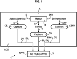
Fig. 1 ] représente schématiquement une partie d'un dispositif de suivi suivant l'invention. - [
Fig. 2 ] représente schématiquement une partie du dispositif de suivi suivant un mode de réalisation de l'invention. - [
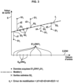
Fig. 3 ] représente un diagramme montrant des sorties d'un modèle calculé par le dispositif de suivi suivant un mode de réalisation de l'invention en ordonnées, en fonction d'entrées du modèle en abscisses. - [
Fig. 4 ] représente un diagramme montrant des sorties d'un modèle calculé par le dispositif de suivi suivant un autre mode de réalisation de l'invention en ordonnées, en fonction d'entrées du modèle en abscisses. - [
Fig. 5 ] représente un diagramme montrant des sorties d'un modèle calculé par le dispositif de suivi suivant un autre mode de réalisation de l'invention en ordonnées, en fonction d'entrées du modèle en abscisses. - [
Fig. 6 ] représente un organigramme d'un procédé de suivi suivant l'invention.
- [
Fig. 1 ] schematically represents part of a tracking device according to the invention. - [
Fig. 2 ] schematically represents a part of the tracking device according to an embodiment of the invention. - [
Fig. 3 ] represents a diagram showing outputs of a model calculated by the tracking device according to an embodiment of the invention on the ordinate, as a function of inputs of the model on the abscissa. - [
Fig. 4 ] represents a diagram showing outputs of a model calculated by the tracking device according to another embodiment of the invention on the ordinate, as a function of inputs of the model on the abscissa. - [
Fig. 5 ] represents a diagram showing outputs of a model calculated by the tracking device according to another embodiment of the invention on the ordinate, as a function of inputs of the model on the abscissa. - [
Fig. 6 ] represents a flowchart of a monitoring method according to the invention.
Aux
- des valeurs E1i de variables E d'entrée (grandeurs physiques) du moteur M lors du vol Vi,
- des valeurs ENV1i de variables ENV (grandeurs physiques) de l'environnement du moteur M lors du vol Vi, et
- des valeurs S1i de variables S de sortie (grandeurs physiques) du moteur M lors du vol Vi.
- values E1 i of input variables E (physical quantities) of the engine M during flight V i ,
- ENV1 i values of ENV variables (physical quantities) of the environment of the engine M during the flight V i , and
- values S1 i of output variables S (physical quantities) of the engine M during flight V i .
Les valeurs E1i, ENV1i et S1i sont acquises pendant le vol Vi et sont associées l'une à l'autre pour chaque vol Vi considéré.The values E1 i , ENV1 i and S1 i are acquired during the flight V i and are associated with each other for each flight V i considered.
Le module ACQ d' acquisition peut être partiellement ou totalement embarqué sur le ou les moteurs M de l'aéronef ou sur l'aéronef. L'aéronef peut être par exemple un avion ou un hélicoptère. Le moteur M de propulsion de l'aéronef peut être une turbomachine, telle que par exemple un turboréacteur, ou autres. Le module ACQ d'acquisition peut comporter des premiers capteurs CE pour mesurer les valeurs E1i des variables E d'entrée du moteur lors du vol Vi, et/ou des deuxièmes capteurs CENV pour mesurer les valeurs ENV1i des variables ENV d'environnement du moteur M lors du vol Vi et/ou des troisièmes capteurs CS pour mesurer les valeurs S1i des variables S de sortie du moteur M lors du vol Vi.The ACQ acquisition module may be partially or completely embedded on the engine(s) M of the aircraft or on the aircraft. The aircraft may be, for example, an airplane or a helicopter. The propulsion engine M of the aircraft may be a turbomachine, such as, for example, a turbojet, or others. The ACQ acquisition module may comprise first CE sensors for measuring the values E1 i of the input variables E of the engine during the flight V i , and/or second CENV sensors for measuring the values ENV1 i of the environmental variables ENV of the engine M during the flight V i and/or third CS sensors for measuring the values S1 i of the output variables S of the engine M during the flight V i .
Les variables E d'entrée du moteur sont des variables de commande sur lesquelles des commandes du pilote de l'aéronef peuvent agir pour commander le moteur. Les variables E d'entrée du moteur peuvent comprendre par exemple une vitesse de rotation du moteur M et/ou une commande du pilote envoyée au moteur M et/ou un couple de commande du moteur M et/ou autres. Les variables ENV d'environnement du moteur M sont des variables extérieures au moteur M et non contrôlables, et peuvent comprendre par exemple une température extérieure et/ou une pression extérieure et/ou un taux d'humidité et/ou une présence de pollution et/ou autres. Les variables S de sortie du moteur M sont des variables résultant des variables E d'entrée et des variables ENV d'environnement et peuvent comprendre par exemple une température du moteur M et/ou un couple de rotation du rotor du moteur M et/ou une consommation instantanée de carburant du moteur M et/ou autres.The engine input variables E are control variables on which commands from the aircraft pilot can act to control the engine. The engine input variables E may include, for example, a rotational speed of the engine M and/or a pilot command sent to the engine M and/or a control torque of the engine M and/or others. The environment variables ENV of the engine M are variables external to the engine M and non-controllable, and may include, for example, an external temperature and/or an external pressure and/or a humidity level and/or a presence of pollution and/or others. The output variables S of the engine M are variables resulting from the input variables E and the environment variables ENV and may include, for example, a temperature of the engine M and/or a rotational torque of the rotor of the engine M and/or an instantaneous fuel consumption of the engine M and/or others.
Le module ACQ d' acquisition peut par exemple enregistrer dans une mémoire embarquée sur l'aéronef, par exemple dans son calculateur de bord ou dans un boîtier embarqué sur l'aéronef, les données DVi de vols Vi comportant les valeurs E1i, ENV1i et S1i mentionnées ci-dessus. Les données DVi de vols Vi peuvent être extraites de la mémoire au sol après chaque vol Vi pour être envoyées aux autres modules décrits ci-dessous du dispositif 1 de suivi.The acquisition ACQ module can for example record in a memory on board the aircraft, for example in its on-board computer or in a box on board the aircraft, the data DV i of flights V i comprising the values E1 i , ENV1 i and S1 i mentioned above. The data DV i of flights V i can be extracted from the ground memory after each flight V i to be sent to the other modules described below of the
Ainsi qu'illustré à la
Suivant un mode de réalisation de l'invention, d'une manière générale pour des deuxièmes valeurs E2i quelconques des variables E d'entrée du moteur du vol Vi et de deuxièmes valeurs ENV2i des variables ENV d'environnement, chaque modèle fi individuel de vol V permet de calculer par le module APPR des estimations de valeurs S2i=fi(E2i, ENV2i) des variables S de sortie du moteur du vol Vi en fonction de ces deuxièmes valeurs E2i et ENV2i des variables ENV d'environnement du moteur du vol Vi (ou inversement), de telle sorte que, lorsque pour le vol Vi les deuxièmes valeurs E2i, ENV2i des variables E d'entrée du moteur et des variables ENV d'environnement du moteur sont égales aux premières valeurs E1i, ENV1i des variables E d'entrée du moteur et des variables ENV d'environnement du moteur M, les deuxièmes valeurs S2 des variables S de sortie du moteur M approchent ou sont sensiblement égales aux premières valeurs S1i des variables S de sortie du moteur M pour le vol Vi . Les premières valeurs E1i, ENV1i, Si des variables E d'entrée de moteur, des variables ENV d'environnement du moteur M et des variables S de sortie du moteur M sont un ensemble de données d'apprentissage du modèle fi individuel de vol. Par exemple, dans ce qui suit, les modèles fi peuvent n'être utilisés que sur les variables de références, ENVR et ER.Le dispositif 1 de suivi comporte un module MUT d'utilisation des modèles fi individuels de vol Vi, ayant été calculés par le module APPR d'apprentissage. Le module MUT d'utilisation est configuré pour calculer, pour chaque vol Vi, les estimations des valeurs S2i=fi(ER, ENVR) des variables S de sortie du moteur correspondant à des valeurs ER de référence des variables E d'entrée du moteur M et à des valeurs ENVR de référence des variables ENV d'environnement du moteur M. Ces estimations de valeurs S2i=fi(ER, ENVR) sont donc calculées par le module MUT d'utilisation appliquant le modèle fi individuel de vol Vi aux valeurs ER de référence des variables E d'entrée du moteur M et aux valeurs ENVR de référence des variables ENV d'environnement du moteur M. Les valeurs ER, ENVR de référence appartiennent à un ensemble prescrit de données DR de référence et qui sont identiques pour la pluralité i des modèles fi individuels de vol Vi. Le module MUT d'utilisation comporte un accès ACC permettant de prescrire ou d'entrer les données DR de référence. Le module MUT d'utilisation du modèle fi applique le modèle fi sur un ensemble DR de référence de données (variables ENVR de vol, variables ER d'entrée). Cet ensemble DR de référence peut être des données précédemment stockées, ou des données simulées. Cet ensemble DR fixé de référence peut être un ou plusieurs vols passés, ou un ou plusieurs vols simulés, ou enfin un ou plusieurs points spécifiques de l'espace de validité du modèle appris fi. Le module d'utilisation MUT de modèle comporte comme entrées le modèle fi et les données DR de références et comme sortie des estimations de grandeurs physiques. L'ensemble DR de référence permet de comparer plusieurs modèles fi appris dans des conditions différentes.According to an embodiment of the invention, generally for any second values E2 i of the input variables E of the engine of the flight V i and second values ENV2 i of the environment ENV variables, each individual model f i of flight V makes it possible to calculate by the APPR module estimates of values S2 i = f i (E2 i , ENV2 i ) of the output variables S of the engine of the flight V i as a function of these second values E2 i and ENV2 i of the environment ENV variables of the engine of the flight V i (or vice versa), such that, when for the flight V i the second values E2 i , ENV2 i of the input variables E of the engine and of the environment ENV variables of the engine are equal to the first values E1 i , ENV1 i of the input variables E of the engine and of the environment ENV variables of the engine M, the second values S2 of the output variables S of the engine M approach or are substantially equal to the first values S1 i of the variables S of engine output M for flight V i . The first values E1 i , ENV1 i , S i of engine input variables E, engine environment variables ENV and engine output variables S are a training data set of the individual flight model f i . For example, in the following, models f i may be used only on the reference variables, ENV R and E R . The
Suivant un mode de réalisation de l'invention, le modèle fi individuel de vol Vi utilise un algorithme pouvant être n'importe quel algorithme de régression tel qu'une régression linéaire, ou un processus gaussien, ou une régression à processus gaussien linéaire, ou une forêt aléatoire, ou un réseau de neurones, ou une régression par la méthode des moindres carrés ou une régression polynomiale d'ordre supérieur ou égal à 2, cet algorithme liant les valeurs calculées des variables S de sortie du moteur M aux valeurs des variables E d'entrée du moteur M et aux variables ENV d'environnement du moteur M. Le module MUT estime la fiabilité du modèle, en comparant l'ensemble d'apprentissage et l'ensemble DR de référence, et/ou en utilisant l'erreur d'apprentissage. Dans le premier cas, un exemple possible de réalisation est l'utilisation d'une méthode de régression fournissant une telle estimation, telle que les processus gaussiens ou toute autre méthode probabiliste. Une autre possibilité est d'utiliser la distance entre les deux ensembles, telle que la distance de Chamfer. Pour l'erreur d'apprentissage, il est possible d'utiliser toute technique d'estimation, comme par exemple tester le modèle sur un ensemble de données non utilisés lors de l'apprentissage (cet ensemble est souvent dénommé ensemble de validation dans l'état de l'art).According to one embodiment of the invention, the individual flight model V i uses an algorithm that can be any regression algorithm such as a linear regression, or a Gaussian process, or a linear Gaussian process regression, or a random forest, or a neural network, or a regression by the least squares method or a polynomial regression of order greater than or equal to 2, this algorithm linking the calculated values of the output variables S of the engine M to the values of the input variables E of the engine M and to the environment variables ENV of the engine M. The MUT module estimates the reliability of the model, in comparing the training set and the reference DR set, and/or using the training error. In the first case, a possible example of implementation is the use of a regression method providing such an estimate, such as Gaussian processes or any other probabilistic method. Another possibility is to use the distance between the two sets, such as the Chamfer distance. For the training error, it is possible to use any estimation technique, such as testing the model on a data set not used during training (this set is often called a validation set in the state of the art).
Suivant un autre mode de réalisation de l'invention, le modèle fi individuel de vol Vi peut lier les valeurs calculées des variables S de sortie du moteur M aux valeurs des variables E d'entrée du moteur M et aux variables ENV d'environnement du moteur M.According to another embodiment of the invention, the individual flight model V i can link the calculated values of the output variables S of the engine M to the values of the input variables E of the engine M and to the environment variables ENV of the engine M.
Le module MUT d'utilisation est configuré pour également calculer, pour chaque vol Vi, une erreur εi associée aux estimations de valeurs S de sortie calculées par le modèle fi individuel de vol Vi. Cette erreur εi est donc calculée par le module MUT d'utilisation à partir du modèle fi individuel de vol Vi.The MUT usage module is configured to also calculate, for each flight V i , an error ε i associated with the output value estimates S calculated by the individual flight model f i V i . This error ε i is therefore calculated by the MUT usage module from the individual flight model f i V i .
L'information INF de suivi décrite ci-dessous ou les estimation de valeurs S2i=fi(ER, ENVR) des variables S de sortie associées à l'erreur εi permettent à l'utilisateur de surveiller chaque vol Vi l'un après l'autre et de pouvoir observer des dérives ou des phénomènes anormaux du vol Vi. Par exemple, le module MUT d'utilisation est configuré pour surveiller si les deuxièmes valeurs S2i augmentent puis diminuent entre les vols Vi-1, Vi, Vi+1 et si l'erreur εi associée reste faible (l'erreur εi associée reste sous un seuil prescrit), pour dans l'affirmative à la fois sur ces deux conditions déclencher automatiquement une alarme sur une ou plusieurs sorties physiques SP de présentation d'informations à un utilisateur (écran d'affichage et/ou autres), cette alarme indiquant qu'il existe un problème sur le moteur M surveillé ou sur l'aéronef ayant ce moteur M surveillé. Le dispositif et le procédé de suivi suivant l'invention peuvent permettre de comparer les différents modèles fi entre eux, en utilisant les modèles fi sur l'ensemble de référence.The tracking information INF described below or the estimates of values S2 i =f i (E R , ENV R ) of the output variables S associated with the error ε i allow the user to monitor each flight V i one after the other and to be able to observe drifts or abnormal phenomena of the flight V i . For example, the MUT module of use is configured to monitor whether the second values S2 i increase then decrease between flights V i-1 , V i , V i+1 and whether the associated error ε i remains low (the associated error ε i remains below a prescribed threshold), in order to, in the affirmative, on both these conditions, automatically trigger an alarm on one or more physical outputs SP for presenting information to a user (display screen and/or others), this alarm indicating that there is a problem on the engine M monitored or on the aircraft having this engine M monitored. The tracking device and method according to the invention can make it possible to compare the different models f i with each other, using the models f i on the reference set.
Le dispositif 1 de suivi peut comporter une ou plusieurs sorties physiques SP de présentation d'informations à un utilisateur (écran d'affichage et/ou autres), pour fournir l'information INF de suivi du moteur pour le vol Vi. Cette information INF de suivi est déterminée par le module MUT d'utilisation au moins à partir des deuxièmes valeurs S2i=fi(ER, ENVR) des variables S de sortie du moteur ayant été calculées et à partir de l'erreur εi associée au modèle fi individuel de vol Vi, ayant été calculée. Par exemple, cette information INF est le couple (S2i, εi). Le dispositif 1 peut comporter un module de suivi automatique de ruptures, tendances et anomalies dans le couple (S2i, εi), mis en oeuvre par un calculateur et ayant en entrées les estimations de grandeurs physiques et les estimations d'erreurs, et en sorties : une information INF signalant des ruptures et/ou des tendances et/ou des anomalies. En variante, l'utilisateur peut également utiliser une approche visuelle, pour remarquer les tendances, anomalies et ruptures, ou tout algorithme automatique de suivi de séries temporelles, mis en oeuvre par un calculateur. En fonction du résultat de ce suivi, une opération de maintenance ou un conseil d'utilisation du moteur M surveillé peut être émis à destination du client exploitant le moteur M surveillé et/ou l'aéronef.The
Suivant un mode de réalisation de l'invention, illustré à la
- les valeurs S1i des variables S de sortie du moteur M, et
- des estimations de valeurs S3i des variables S de sortie du moteur M, qui sont calculées en appliquant le modèle fi individuel de vol Vi aux premières valeurs E1i de variables E d'entrée du moteur et aux premières valeurs ENV1i de variables ENV d'environnement du moteur M, associées aux premières valeurs S1i des variables S de sortie du moteur M. Cette distance d peut être calculée comme étant la moyenne des distances individuelles d1, d2, d3, d4, d5 entre chaque première valeur S1i et chaque troisième valeur S3i. Par exemple, cette erreur εi peut être calculée en supposant que les premières valeurs ENV1i des variables ENV d'environnement sont les mêmes pour les différentes valeurs E1i et S1i. Par exemple, à la
figure 3 , le modèle fi individuel de vol Vi peut être une régression linéaire liant les deuxièmes valeurs de sortie S2i aux premières valeurs ER, ENVR et liant les troisièmes valeurs de sortie S3i aux premières valeurs E1i, ENV1i.
- the values S1 i of the output variables S of the motor M, and
- estimates of values S3 i of the output variables S of the engine M, which are calculated by applying the individual flight model f i to the first values E1 i of the input variables E of the engine and to the first values ENV1 i of the environmental variables ENV of the engine M, associated with the first values S1 i of the output variables S of the engine M. This distance d can be calculated as the average of the individual distances d1, d2, d3, d4, d5 between each first value S1 i and each third value S3 i . For example, this error ε i can be calculated by assuming that the first values ENV1 i of the environmental variables ENV are the same for the different values E1 i and S1 i . For example, at
figure 3 , the individual flight model V i can be a linear regression linking the second values output S2 i to the first values E R , ENV R and linking the third output values S3 i to the first values E1 i , ENV1 i .
Suivant un mode de réalisation de l'invention, illustré à la
- les valeurs ER de référence des variables E d'entrée du moteur M, et
- les premières valeurs E1i de variables E d'entrée du moteur.
- the reference E R values of the input E variables of the motor M, and
- the first values E1 i of input variables E of the motor.
Cette distance d(ER, E1i) peut être une distance entre des ensembles de points, par exemple une distance de Hausdorff. Par exemple, cette erreur εi peut être calculée en supposant que les premières valeurs ENV1i des variables ENV d'environnement sont les mêmes pour les différentes valeurs E1i et S1i. Par exemple, à la
Suivant un mode de réalisation de l'invention, illustré à la
L'erreur εi associée au modèle fi individuel de vol Vi comprend ou est cette estimation EM d'erreur de modélisation du modèle fi individuel de vol. Le module APPR d'apprentissage peut être configuré pour calculer par apprentissage, à partir des premières données DVi de chaque vol Vi, une estimation EM d'erreur de modélisation du modèle fi individuel de vol sur les variables S de sortie du moteur M, ainsi qu'illustré aux
- une erreur CEM calculée en fonction des premières valeurs E1i de variables E d'entrée du moteur et/ou des premières valeurs ENV1i de variables ENV d'environnement du moteur M, et
- les estimations de valeurs S2i des variables S de sortie du moteur M, qui sont calculées en appliquant le modèle fi individuel de vol Vi aux valeurs ER de référence des variables E d'entrée du moteur M et aux valeurs ENVR de référence des variables ENV d'environnement du moteur M. Cette distance d' peut être calculée comme étant la moyenne des distances individuelles d'1, d'2, d'3 entre chaque deuxième valeur S2i et l'erreur. Par exemple, cette estimation EM d'erreur de modélisation peut être calculée en supposant que les premières valeurs ENV1i des variables ENV d'environnement sont les mêmes pour les différentes valeurs ER et ENVR. Par exemple, à la
figure 5 , le modèle fi individuel de vol Vi peut être régression à processus gaussien linéaire, liant les deuxièmes valeurs de sortie S2i aux premières valeurs ER, ENVR et liant les troisièmes valeurs de sortie S3i aux premières valeurs E1i, ENV1i.
- an EMC error calculated based on the first values E1 i of motor input variables E and/or the first values ENV1 i of motor environment variables ENV of motor M, and
- the estimates of values S2 i of the output variables S of the engine M, which are calculated by applying the individual flight model f i to the reference values E R of the input variables E of the engine M and to the reference values ENV R of the environment variables ENV of the engine M. This distance d' can be calculated as the average of the individual distances d'1, d'2, d'3 between each second value S2 i and the error. For example, this estimate EM of modeling error can be calculated by assuming that the first values ENV1 i of the environment variables ENV are the same for the different values E R and ENV R . For example, at
figure 5 , the individual flight model V i can be linear Gaussian process regression, relating the second output values S2 i to the first values E R , ENV R and relating the third output values S3 i to the first values E1 i , ENV1 i .
Suivant un mode de réalisation de l'invention, au moins certaines (ou toutes) des valeurs ER de référence et/ou au moins certaines (ou toutes) des valeurs ENVR de référence et/ou au moins certaines (ou toutes) des valeurs SR de référence sont prescrites en association les unes aux autres dans l'ensemble prescrit de données DR de référence.According to one embodiment of the invention, at least some (or all) of the reference E R values and/or at least some (or all) of the reference ENV R values and/or at least some (or all) of the reference S R values are prescribed in association with each other in the prescribed set of reference DR data.
Suivant un mode de réalisation de l'invention, au moins certaines (ou toutes) des valeurs ER de référence et/ou au moins certaines (ou toutes) des valeurs ENVR de référence et/ou au moins certaines (ou toutes) des valeurs SR de référence sont des premières données DV de vol ayant été obtenues par le module ACQ d'acquisition pour au moins un vol Vi effectué. Autrement dit, le ou les vols VR de référence peuvent être un ou des vols Vi effectués.According to one embodiment of the invention, at least some (or all) of the reference E R values and/or at least some (or all) of the reference ENV R values and/or at least some (or all) of the reference S R values are first flight DV data having been obtained by the acquisition ACQ module for at least one flight V i performed. In other words, the reference flight(s) V R may be one or more flights V i performed.
Suivant un mode de réalisation de l'invention, au moins certaines (ou toutes) des valeurs ER de référence et/ou au moins certaines (ou toutes) des valeurs ENVR de référence et/ou au moins certaines (ou toutes) des valeurs SR de référence sont des premières données DV de vol ayant été simulées pour au moins un vol Vi non effectué réellement par l'aéronef. Autrement dit, le ou les vols VR de référence peuvent être un ou des vols Vi simulés et non effectués réellement par l'aéronef.According to one embodiment of the invention, at least some (or all) of the reference E R values and/or at least some (or all) of the reference ENV R values and/or at least some (or all) of the reference S R values are first flight DV data having been simulated for at least one flight V i not actually performed by the aircraft. In other words, the reference flight(s) V R may be one or more simulated flights V i not actually performed by the aircraft.
Le dispositif 1 de suivi permet de mettre en oeuvre un procédé de suivi temporel de l'état d'au moins un moteur M de propulsion d'au moins un aéronef A, qui comporte les étapes décrites ci-dessous en référence à la
Au cours d'une première étape 11, on acquiert par le module ACQ d'acquisition les données DVi décrites ci-dessus.During a
Au cours d'une deuxième étape 12 postérieure à la première étape 11, on calcule par le module APPR d'apprentissage le modèle fi individuel de vol décrit ci-dessus.During a
Au cours d'une troisième étape 13 postérieure à la deuxième étape 12 ou simultanée à la deuxième étape 12, on calcule par le module MUT d'utilisation des modèles fi individuels de vol Vi pour chaque vol Vi les deuxièmes valeurs S2i=fi(ER, ENVR) et l'erreur εi associée à S2i et au modèle (fi) individuel de vol Vi, ainsi que décrit ci-dessus.During a
Le procédé de suivi peut mettre en oeuvre l'un et/ou l'autre des modes de réalisation décrits ci-dessus.The tracking method may implement one and/or the other of the embodiments described above.
Le dispositif 1 de suivi et ses modules APPR, MUT, MTF peuvent être mis en oeuvre par un ou plusieurs calculateurs, tels que par exemple un ou plusieurs ordinateurs, ou autres moyens de calcul. Le dispositif 1 de suivi peut comporter un programme d'ordinateur, enregistré dans une mémoire permanente de celui-ci, pour mettre en oeuvre les modules APPR, MUT, MTF et pour exécuter les étapes du procédé de suivi.The
Bien entendu, les modes de réalisation, caractéristiques, possibilités et exemples décrits ci-dessus peuvent être combinés l'un avec l'autre ou être sélectionnés indépendamment l'un de l'autre, dans le cadre défini par les revendications suivantes.Of course, the embodiments, features, possibilities and examples described above can be combined with each other or selected independently of each other, within the scope defined by the following claims.
Claims (11)
- A device for monitoring over time a state of at least one propulsion engine (M) of at least one aircraft (A), wherein the device comprisesa module (ACQ) for acquiring data (DVi) of flights (Vi) of the at least one propulsion engine (M) of the at least one aircraft (A), comprising, in association for each flight (Vi), values (E1i) of input variables (E) of the engine during the flight (Vi), values (ENV1i) of environment variables (ENV) of the engine (M) during the flight (Vi) and values (S1i) of output variables (S) of the engine (M) during the flight (Vi),a learning module (APPR) configured to compute by learning from the data (DVi) of each flight (Vi) an individual flight model (fi) for the flight (Vi), linking the input variables (E) of the engine (M), the environment variables (ENV) of the engine (M) and the output variables (S) of the engine (M),and characterized by comprisinga using module (MUT) for using the individual flight (Vi) models (fi), configured to compute, for each flight (Vi):estimates of the values (S2i=fi(ER, ENVR)) of the output variables (S) of the engine, which are obtained by applying the individual flight (Vi) model (fi) to reference values (ER) of the input variables (E) of the engine (M) and to reference values (ENVR) of the environment variables (ENV) of the engine (M), andan error (εi) associated with said estimates of the values (S2i=fi(ER, ENVR)) of the output variables (S) of the engine, which have been generated by the individual flight (Vi) model (fi) and which have been obtained by applying the individual flight (Vi) model (fi) to the reference values (ER) of the input variables (E) of the engine (M) and to the reference values (ENVR) of the environment variables (ENV) of the engine (M),wherein the reference values (ER, ENVR, SR) belong to a prescribed set of reference data (DR), which are identical for the plurality (i) of individual flight (Vi) models (fi).
- The device according to claim 1, comprising at least one physical output (SP) for presenting information to a user, to supply an item of engine monitoring information (INF) for the flight (Vi) which is determined by the using module (MUT) at least from the estimates of the values (S2i=fi(ER, ENVR)) of the output variables (S) of the engine and from the error (εi) associated with these estimates and with the individual flight (Vi) model (fi).
- The device according to claim 2, wherein the item of engine monitoring information (INF) for the flight (Vi) is formed by the pair constituted by the estimates of the values (S2i=fi(ER, ENVR)) of the output variables (S) of the engine and the error (εi) associated with the estimates and with the individual flight (Vi) model (fi).
- The device according to any one of the preceding claims, characterized in that the error (εi) associated with the estimates and with the individual flight (Vi) model (fi) comprises a distance computed betweenthe values (S1i) of the output variables (S) of the engine (M) andestimates of the values (S3i) of the output variables (S) of the engine (M), computed by the individual flight (Vi) model (fi) applied to the values (E1i) of the input variables (E) of the engine and to the values (ENV1i) of the environment parameters (ENV) of the engine (M), associated with the values (S1i) of the output variables (S) of the engine (M).
- The device according to any one of the preceding claims, characterized in that the error (εi) associated with the individual flight (Vi) model (fi) comprises a distance computed betweenthe reference values (ER) of the input variables (E) of the engine (M) associated with the reference values (ENVR) of the environment variables (ENV) of the engine andthe values (E1i) of the input variables (E) of the engine associated with the values (ENVi) of the environment variables (ENV) of the engine of the flight (Vi).
- The device according to any one of the preceding claims, characterized in that the learning module (APPR) is configured to compute, by learning from the data (DVi) of each flight (Vi), an estimate of modeling error of the individual flight model (fi) on the output variables (S) of the engine (M),
wherein the error (εi) associated with the individual flight (Vi) model (fi) comprises said estimate of modeling error of the individual flight model (fi). - The device according to any one of the preceding claims, characterized in that at least some of the reference values (ER) of the reference input variables (E) of the engine (M) and/or of the reference values (ENVR) of the environment variables (ENV) of the engine (M) and/or of the reference values (SR) of the output variables (S) of the engine (M) are prescribed in association with one another in the prescribed set of reference data (DR).
- The device according to any one of the preceding claims, characterized in that at least some of the reference values (ER) of the reference input variables (E) of the engine (M) and/or of the reference values (ENVR) of the environment variables (ENV) of the engine (M) and/or of the reference values (SR) of the output variables (S) of the engine (M) are flight data (DV) which have been obtained by the acquisition module (ACQ) for at least one flight (Vi) carried out.
- The device according to any one of the preceding claims, characterized in that at least some of the reference values (ER) of the reference input variables (E) of the engine (M) and/or of the reference values (ENVR) of the environment variables (ENV) of the engine (M) and/or of the reference values (SR) of the output variables (S) of the engine (M) are flight data (DV) simulated for at least one flight (Vi) not carried out.
- A method for monitoring over time a state of at least one propulsion engine (M) of at least one aircraft (A), in whichdata (DVi) of flight (Vi) of the at least one propulsion engine (M) of the at least one aircraft (A), comprising, in association for each flight (Vi), values (E1i) of input variables (E) of the engine during the flight (Vi), values (ENV1i) of environment variables (ENV) of the engine (M) during the flight (Vi) and values (S1i) of output variables (S) of the engine (M) during the flight (Vi), are acquired (11) by an acquisition module (ACQ),an individual flight model (fi) for the flight (Vi), which links the input variables (E) of the engine (M), the environment variables (ENV) of the engine (M) and the output variables (S) of the engine (M), is computed (12) by a learning module (APPR) from the data (DVi) for each flight (Vi),and characterized by the fact thatestimates of the values (S2i=fi(ER, ENVR)) of the output variables (S) of the engine, which are obtained by applying the individual flight (Vi) model (fi) to reference values (ER) of the input variables (E) of the engine (M) and to reference values (ENVR) of the environment variables (ENV) of the engine (M), and an error (εi) associated with said estimates of the values (S2i=fi(ER, ENVR)) of the output variables (S) of the engine, which have been generated by the individual flight (Vi) model (fi) and which have been obtained by applying the individual flight (Vi) model (fi) to the reference values (ER) of the input variables (E) of the engine (M) and to the reference values (ENVR) of the environment variables (ENV) of the engine (M), are computed (13) by a using module (MUT) using the individual flight (Vi) models (fi), for each flight (Vi),wherein the reference values (ER, ENVR, SR) belong to a prescribed set of reference data (DR) which are identical for the plurality (i) of the individual flight (Vi) models (fi).
- A computer program comprising code instructions for implementing the method for monitoring over time a state of at least one propulsion engine (M) of at least one aircraft as claimed in claim 10, when it is implemented on a calculator of the aircraft.
Applications Claiming Priority (2)
| Application Number | Priority Date | Filing Date | Title |
|---|---|---|---|
| FR1911082A FR3101669B1 (en) | 2019-10-07 | 2019-10-07 | Aircraft engine tracking computer device, method and program |
| PCT/FR2020/051741 WO2021069824A1 (en) | 2019-10-07 | 2020-10-05 | Apparatus, method and computer program for monitoring an aircraft engine |
Publications (2)
| Publication Number | Publication Date |
|---|---|
| EP4042007A1 EP4042007A1 (en) | 2022-08-17 |
| EP4042007B1 true EP4042007B1 (en) | 2025-01-01 |
Family
ID=69104736
Family Applications (1)
| Application Number | Title | Priority Date | Filing Date |
|---|---|---|---|
| EP20796633.4A Active EP4042007B1 (en) | 2019-10-07 | 2020-10-05 | Apparatus, method and computer program for monitoring an aircraft engine |
Country Status (4)
| Country | Link |
|---|---|
| US (1) | US11807388B2 (en) |
| EP (1) | EP4042007B1 (en) |
| FR (1) | FR3101669B1 (en) |
| WO (1) | WO2021069824A1 (en) |
Families Citing this family (2)
| Publication number | Priority date | Publication date | Assignee | Title |
|---|---|---|---|---|
| CN113377027A (en) * | 2021-05-26 | 2021-09-10 | 中国航空工业集团公司沈阳飞机设计研究所 | An aircraft propulsion system test system |
| CN114744824A (en) * | 2022-05-11 | 2022-07-12 | 星河智源(深圳)科技有限公司 | Energy-saving and environment-friendly intelligent output motor capable of independently controlling rotating speed |
Family Cites Families (28)
| Publication number | Priority date | Publication date | Assignee | Title |
|---|---|---|---|---|
| US6216066B1 (en) * | 1998-07-01 | 2001-04-10 | General Electric Company | System and method for generating alerts through multi-variate data assessment |
| US6799154B1 (en) * | 2000-05-25 | 2004-09-28 | General Electric Comapny | System and method for predicting the timing of future service events of a product |
| US6832205B1 (en) * | 2000-06-30 | 2004-12-14 | General Electric Company | System and method for automatically predicting the timing and costs of service events in a life cycle of a product |
| US6466858B1 (en) * | 2000-11-02 | 2002-10-15 | General Electric Company | Methods and apparatus for monitoring gas turbine engine operation |
| US7457732B2 (en) * | 2001-08-17 | 2008-11-25 | General Electric Company | System and method for measuring quality of baseline modeling techniques |
| US7383165B2 (en) * | 2001-08-17 | 2008-06-03 | General Electric Company | System and method for diagnosing faults utilizing baseline modeling techniques |
| US6823675B2 (en) * | 2002-11-13 | 2004-11-30 | General Electric Company | Adaptive model-based control systems and methods for controlling a gas turbine |
| US6962043B2 (en) * | 2003-01-30 | 2005-11-08 | General Electric Company | Method and apparatus for monitoring the performance of a gas turbine system |
| US7734400B2 (en) * | 2003-07-24 | 2010-06-08 | Honeywell International Inc. | Fault detection system and method using augmented data and fuzzy logic |
| US7031812B1 (en) * | 2004-03-15 | 2006-04-18 | Howell Instruments, Inc. | System and method for monitoring aircraft engine health and determining engine power available, and applications thereof |
| US7062370B2 (en) * | 2004-03-30 | 2006-06-13 | Honeywell International Inc. | Model-based detection, diagnosis of turbine engine faults |
| US7487029B2 (en) * | 2004-05-21 | 2009-02-03 | Pratt & Whitney Canada | Method of monitoring gas turbine engine operation |
| JP5043839B2 (en) * | 2005-07-11 | 2012-10-10 | ブルックス オートメーション インコーポレイテッド | Intelligent condition monitoring and fault diagnosis system for predictive maintenance |
| US7286923B2 (en) * | 2005-09-30 | 2007-10-23 | General Electric Company | System and method for estimating turbine engine deterioration rate with noisy data |
| US20090048730A1 (en) * | 2007-08-17 | 2009-02-19 | General Electric Company | Method and system for planning repair of an engine |
| US8165826B2 (en) * | 2008-09-30 | 2012-04-24 | The Boeing Company | Data driven method and system for predicting operational states of mechanical systems |
| US8600917B1 (en) * | 2011-04-18 | 2013-12-03 | The Boeing Company | Coupling time evolution model with empirical regression model to estimate mechanical wear |
| US8720258B2 (en) | 2012-09-28 | 2014-05-13 | United Technologies Corporation | Model based engine inlet condition estimation |
| FR3003032B1 (en) | 2013-03-07 | 2015-04-03 | Turbomeca | METHOD AND SYSTEM FOR CONTROLLING THE HEALTH OF AN AIRCRAFT TURBOMACHINE |
| GB201315654D0 (en) * | 2013-09-03 | 2013-10-16 | Rolls Royce Plc | Operating parameter monitoring method |
| FR3028331B1 (en) * | 2014-11-10 | 2016-12-30 | Snecma | METHOD FOR MONITORING AN AIRCRAFT ENGINE IN OPERATION IN A GIVEN ENVIRONMENT |
| FR3046268B1 (en) * | 2015-12-23 | 2019-05-10 | Safran Aircraft Engines | AIRCRAFT FLIGHT DATA OPERATION SYSTEM |
| FR3052273B1 (en) * | 2016-06-02 | 2018-07-06 | Airbus | PREDICTION OF TROUBLES IN AN AIRCRAFT |
| US20180268288A1 (en) * | 2017-03-14 | 2018-09-20 | General Electric Company | Neural Network for Steady-State Performance Approximation |
| US10508597B2 (en) | 2017-04-12 | 2019-12-17 | General Electric Company | Systems and methods for icing detection of compressors |
| US10604278B2 (en) * | 2017-04-18 | 2020-03-31 | General Electric Company | Methods and apparatus to monitor health information of a turbine engine |
| FR3095271B1 (en) * | 2019-04-18 | 2021-07-30 | Safran | Helicopter health monitoring system |
| FR3095424B1 (en) * | 2019-04-23 | 2024-10-04 | Safran | System and method for monitoring an aircraft engine |
-
2019
- 2019-10-07 FR FR1911082A patent/FR3101669B1/en active Active
-
2020
- 2020-10-05 WO PCT/FR2020/051741 patent/WO2021069824A1/en not_active Ceased
- 2020-10-05 EP EP20796633.4A patent/EP4042007B1/en active Active
- 2020-10-05 US US17/765,309 patent/US11807388B2/en active Active
Also Published As
| Publication number | Publication date |
|---|---|
| US11807388B2 (en) | 2023-11-07 |
| FR3101669B1 (en) | 2022-04-08 |
| US20220371745A1 (en) | 2022-11-24 |
| WO2021069824A1 (en) | 2021-04-15 |
| FR3101669A1 (en) | 2021-04-09 |
| EP4042007A1 (en) | 2022-08-17 |
Similar Documents
| Publication | Publication Date | Title |
|---|---|---|
| EP2912526B1 (en) | System for monitoring a set of components of a device | |
| EP2500267B1 (en) | Monitoring of a flight control actuator of an aircraft | |
| EP3956646B1 (en) | System for monitoring the health of a helicopter | |
| FR2970358A1 (en) | PROGNOSTIC OF DURATION BEFORE MAINTENANCE BY FUSION BETWEEN MODELING AND SIMULATION, FOR ELECTRONIC EQUIPMENTS ON BOARD IN AN AIRCRAFT | |
| EP2966526B1 (en) | A method and a system for merging health indicators of a device | |
| FR3052273A1 (en) | PREDICTION OF TROUBLES IN AN AIRCRAFT | |
| FR2965915A1 (en) | SYSTEM FOR MONITORING AN AIRCRAFT ENGINE TEST BENCH | |
| FR3035232A1 (en) | SYSTEM FOR MONITORING THE HEALTH CONDITION OF AN ENGINE AND ASSOCIATED CONFIGURATION METHOD | |
| EP3215903B1 (en) | Tool for validating a system for monitoring an aircraft engine | |
| EP0657723A1 (en) | Method and apparatus for detecting a load dimensioning overrun of an aircraft | |
| FR3046268A1 (en) | AIRCRAFT FLIGHT DATA OPERATION SYSTEM | |
| EP4042007B1 (en) | Apparatus, method and computer program for monitoring an aircraft engine | |
| FR3095424A1 (en) | System and method for monitoring an aircraft engine | |
| FR2991486A1 (en) | METHOD AND DEVICE FOR ASSISTANCE IN FOLLOWING MISSION OF AN AIRCRAFT | |
| FR2963960A1 (en) | PARTICLE MONITORING IN A LUBRICATION SYSTEM | |
| EP4464997B1 (en) | Method and device for monitoring the health of a mechanical system of a vehicle by using thresholds that vary depending on operating parameters of the system | |
| EP3489831A1 (en) | Method and device for monitoring a data generator process of a metric for the prediction of abnormalities | |
| CA2837523A1 (en) | System for recommending helicopter engine maintenance | |
| FR2957170A1 (en) | Equipment monitoring system designing tool for engine of aircraft, involves processing unit evaluating quantification of monitoring system based on quality value of result corresponding to output quality value associated with output module | |
| EP4559769B1 (en) | Method for monitoring the temperature of the brakes of an aircraft landing gear | |
| CA2928844A1 (en) | Engine failure management process and device for an aircraft turbine engine | |
| FR3003986A1 (en) | METHOD FOR DETECTING AND TAKING INTO ACCOUNT A CHANGE ABRUPTED FROM AT LEAST ONE DEVICE MONITORING INDICATOR. | |
| FR3113747A1 (en) | Electronic system for implementing a critical function and associated method | |
| FR2979013A1 (en) | AIRCRAFT ENGINE TEST BENCH MONITORING SYSTEM | |
| FR2966878A1 (en) | System for monitoring validity of temperature measurement chain of exhaust gases of jet engine of aircraft, has computer analyzing results of statistical test on abnormality detection indicator to assess validity of chain |
Legal Events
| Date | Code | Title | Description |
|---|---|---|---|
| STAA | Information on the status of an ep patent application or granted ep patent |
Free format text: STATUS: UNKNOWN |
|
| STAA | Information on the status of an ep patent application or granted ep patent |
Free format text: STATUS: THE INTERNATIONAL PUBLICATION HAS BEEN MADE |
|
| PUAI | Public reference made under article 153(3) epc to a published international application that has entered the european phase |
Free format text: ORIGINAL CODE: 0009012 |
|
| STAA | Information on the status of an ep patent application or granted ep patent |
Free format text: STATUS: REQUEST FOR EXAMINATION WAS MADE |
|
| 17P | Request for examination filed |
Effective date: 20220503 |
|
| AK | Designated contracting states |
Kind code of ref document: A1 Designated state(s): AL AT BE BG CH CY CZ DE DK EE ES FI FR GB GR HR HU IE IS IT LI LT LU LV MC MK MT NL NO PL PT RO RS SE SI SK SM TR |
|
| DAV | Request for validation of the european patent (deleted) | ||
| DAX | Request for extension of the european patent (deleted) | ||
| GRAP | Despatch of communication of intention to grant a patent |
Free format text: ORIGINAL CODE: EPIDOSNIGR1 |
|
| STAA | Information on the status of an ep patent application or granted ep patent |
Free format text: STATUS: GRANT OF PATENT IS INTENDED |
|
| RIC1 | Information provided on ipc code assigned before grant |
Ipc: B64D 45/00 20060101ALI20240830BHEP Ipc: G05B 23/02 20060101ALI20240830BHEP Ipc: F02C 9/00 20060101AFI20240830BHEP |
|
| INTG | Intention to grant announced |
Effective date: 20240918 |
|
| GRAS | Grant fee paid |
Free format text: ORIGINAL CODE: EPIDOSNIGR3 |
|
| GRAA | (expected) grant |
Free format text: ORIGINAL CODE: 0009210 |
|
| STAA | Information on the status of an ep patent application or granted ep patent |
Free format text: STATUS: THE PATENT HAS BEEN GRANTED |
|
| AK | Designated contracting states |
Kind code of ref document: B1 Designated state(s): AL AT BE BG CH CY CZ DE DK EE ES FI FR GB GR HR HU IE IS IT LI LT LU LV MC MK MT NL NO PL PT RO RS SE SI SK SM TR |
|
| REG | Reference to a national code |
Ref country code: GB Ref legal event code: FG4D Free format text: NOT ENGLISH |
|
| REG | Reference to a national code |
Ref country code: CH Ref legal event code: EP |
|
| REG | Reference to a national code |
Ref country code: DE Ref legal event code: R096 Ref document number: 602020044119 Country of ref document: DE |
|
| REG | Reference to a national code |
Ref country code: IE Ref legal event code: FG4D Free format text: LANGUAGE OF EP DOCUMENT: FRENCH |
|
| REG | Reference to a national code |
Ref country code: LT Ref legal event code: MG9D |
|
| REG | Reference to a national code |
Ref country code: NL Ref legal event code: MP Effective date: 20250101 |
|
| REG | Reference to a national code |
Ref country code: AT Ref legal event code: MK05 Ref document number: 1756467 Country of ref document: AT Kind code of ref document: T Effective date: 20250101 |
|
| PG25 | Lapsed in a contracting state [announced via postgrant information from national office to epo] |
Ref country code: NL Free format text: LAPSE BECAUSE OF FAILURE TO SUBMIT A TRANSLATION OF THE DESCRIPTION OR TO PAY THE FEE WITHIN THE PRESCRIBED TIME-LIMIT Effective date: 20250101 |
|
| PG25 | Lapsed in a contracting state [announced via postgrant information from national office to epo] |
Ref country code: FI Free format text: LAPSE BECAUSE OF FAILURE TO SUBMIT A TRANSLATION OF THE DESCRIPTION OR TO PAY THE FEE WITHIN THE PRESCRIBED TIME-LIMIT Effective date: 20250101 |
|
| PG25 | Lapsed in a contracting state [announced via postgrant information from national office to epo] |
Ref country code: PL Free format text: LAPSE BECAUSE OF FAILURE TO SUBMIT A TRANSLATION OF THE DESCRIPTION OR TO PAY THE FEE WITHIN THE PRESCRIBED TIME-LIMIT Effective date: 20250101 |
|
| PG25 | Lapsed in a contracting state [announced via postgrant information from national office to epo] |
Ref country code: ES Free format text: LAPSE BECAUSE OF FAILURE TO SUBMIT A TRANSLATION OF THE DESCRIPTION OR TO PAY THE FEE WITHIN THE PRESCRIBED TIME-LIMIT Effective date: 20250101 |
|
| PG25 | Lapsed in a contracting state [announced via postgrant information from national office to epo] |
Ref country code: NO Free format text: LAPSE BECAUSE OF FAILURE TO SUBMIT A TRANSLATION OF THE DESCRIPTION OR TO PAY THE FEE WITHIN THE PRESCRIBED TIME-LIMIT Effective date: 20250401 Ref country code: IS Free format text: LAPSE BECAUSE OF FAILURE TO SUBMIT A TRANSLATION OF THE DESCRIPTION OR TO PAY THE FEE WITHIN THE PRESCRIBED TIME-LIMIT Effective date: 20250501 |
|
| PG25 | Lapsed in a contracting state [announced via postgrant information from national office to epo] |
Ref country code: HR Free format text: LAPSE BECAUSE OF FAILURE TO SUBMIT A TRANSLATION OF THE DESCRIPTION OR TO PAY THE FEE WITHIN THE PRESCRIBED TIME-LIMIT Effective date: 20250101 |
|
| PG25 | Lapsed in a contracting state [announced via postgrant information from national office to epo] |
Ref country code: LV Free format text: LAPSE BECAUSE OF FAILURE TO SUBMIT A TRANSLATION OF THE DESCRIPTION OR TO PAY THE FEE WITHIN THE PRESCRIBED TIME-LIMIT Effective date: 20250101 Ref country code: PT Free format text: LAPSE BECAUSE OF FAILURE TO SUBMIT A TRANSLATION OF THE DESCRIPTION OR TO PAY THE FEE WITHIN THE PRESCRIBED TIME-LIMIT Effective date: 20250502 |
|
| PG25 | Lapsed in a contracting state [announced via postgrant information from national office to epo] |
Ref country code: GR Free format text: LAPSE BECAUSE OF FAILURE TO SUBMIT A TRANSLATION OF THE DESCRIPTION OR TO PAY THE FEE WITHIN THE PRESCRIBED TIME-LIMIT Effective date: 20250402 Ref country code: BG Free format text: LAPSE BECAUSE OF FAILURE TO SUBMIT A TRANSLATION OF THE DESCRIPTION OR TO PAY THE FEE WITHIN THE PRESCRIBED TIME-LIMIT Effective date: 20250101 |
|
| PG25 | Lapsed in a contracting state [announced via postgrant information from national office to epo] |
Ref country code: AT Free format text: LAPSE BECAUSE OF FAILURE TO SUBMIT A TRANSLATION OF THE DESCRIPTION OR TO PAY THE FEE WITHIN THE PRESCRIBED TIME-LIMIT Effective date: 20250101 |
|
| PG25 | Lapsed in a contracting state [announced via postgrant information from national office to epo] |
Ref country code: CZ Free format text: LAPSE BECAUSE OF FAILURE TO SUBMIT A TRANSLATION OF THE DESCRIPTION OR TO PAY THE FEE WITHIN THE PRESCRIBED TIME-LIMIT Effective date: 20250101 |
|
| PG25 | Lapsed in a contracting state [announced via postgrant information from national office to epo] |
Ref country code: SE Free format text: LAPSE BECAUSE OF FAILURE TO SUBMIT A TRANSLATION OF THE DESCRIPTION OR TO PAY THE FEE WITHIN THE PRESCRIBED TIME-LIMIT Effective date: 20250101 |
|
| REG | Reference to a national code |
Ref country code: DE Ref legal event code: R097 Ref document number: 602020044119 Country of ref document: DE |
|
| PG25 | Lapsed in a contracting state [announced via postgrant information from national office to epo] |
Ref country code: SM Free format text: LAPSE BECAUSE OF FAILURE TO SUBMIT A TRANSLATION OF THE DESCRIPTION OR TO PAY THE FEE WITHIN THE PRESCRIBED TIME-LIMIT Effective date: 20250101 |
|
| PG25 | Lapsed in a contracting state [announced via postgrant information from national office to epo] |
Ref country code: DK Free format text: LAPSE BECAUSE OF FAILURE TO SUBMIT A TRANSLATION OF THE DESCRIPTION OR TO PAY THE FEE WITHIN THE PRESCRIBED TIME-LIMIT Effective date: 20250101 |
|
| PG25 | Lapsed in a contracting state [announced via postgrant information from national office to epo] |
Ref country code: IT Free format text: LAPSE BECAUSE OF FAILURE TO SUBMIT A TRANSLATION OF THE DESCRIPTION OR TO PAY THE FEE WITHIN THE PRESCRIBED TIME-LIMIT Effective date: 20250101 |
|
| PG25 | Lapsed in a contracting state [announced via postgrant information from national office to epo] |
Ref country code: EE Free format text: LAPSE BECAUSE OF FAILURE TO SUBMIT A TRANSLATION OF THE DESCRIPTION OR TO PAY THE FEE WITHIN THE PRESCRIBED TIME-LIMIT Effective date: 20250101 |
|
| PG25 | Lapsed in a contracting state [announced via postgrant information from national office to epo] |
Ref country code: RO Free format text: LAPSE BECAUSE OF FAILURE TO SUBMIT A TRANSLATION OF THE DESCRIPTION OR TO PAY THE FEE WITHIN THE PRESCRIBED TIME-LIMIT Effective date: 20250101 |
|
| PG25 | Lapsed in a contracting state [announced via postgrant information from national office to epo] |
Ref country code: SK Free format text: LAPSE BECAUSE OF FAILURE TO SUBMIT A TRANSLATION OF THE DESCRIPTION OR TO PAY THE FEE WITHIN THE PRESCRIBED TIME-LIMIT Effective date: 20250101 |
|
| PLBE | No opposition filed within time limit |
Free format text: ORIGINAL CODE: 0009261 |
|
| STAA | Information on the status of an ep patent application or granted ep patent |
Free format text: STATUS: NO OPPOSITION FILED WITHIN TIME LIMIT |
|
| 26N | No opposition filed |
Effective date: 20251002 |
|
| PGFP | Annual fee paid to national office [announced via postgrant information from national office to epo] |
Ref country code: DE Payment date: 20251020 Year of fee payment: 6 |
|
| PGFP | Annual fee paid to national office [announced via postgrant information from national office to epo] |
Ref country code: GB Payment date: 20251029 Year of fee payment: 6 |
|
| PGFP | Annual fee paid to national office [announced via postgrant information from national office to epo] |
Ref country code: FR Payment date: 20251024 Year of fee payment: 6 |