EP4042007B1 - Vorrichtung, verfahren und computerprogramm zur überwachung eines flugzeugtriebwerks - Google Patents
Vorrichtung, verfahren und computerprogramm zur überwachung eines flugzeugtriebwerks Download PDFInfo
- Publication number
- EP4042007B1 EP4042007B1 EP20796633.4A EP20796633A EP4042007B1 EP 4042007 B1 EP4042007 B1 EP 4042007B1 EP 20796633 A EP20796633 A EP 20796633A EP 4042007 B1 EP4042007 B1 EP 4042007B1
- Authority
- EP
- European Patent Office
- Prior art keywords
- engine
- flight
- variables
- values
- env
- Prior art date
- Legal status (The legal status is an assumption and is not a legal conclusion. Google has not performed a legal analysis and makes no representation as to the accuracy of the status listed.)
- Active
Links
Images



Classifications
-
- B—PERFORMING OPERATIONS; TRANSPORTING
- B64—AIRCRAFT; AVIATION; COSMONAUTICS
- B64D—EQUIPMENT FOR FITTING IN OR TO AIRCRAFT; FLIGHT SUITS; PARACHUTES; ARRANGEMENT OR MOUNTING OF POWER PLANTS OR PROPULSION TRANSMISSIONS IN AIRCRAFT
- B64D45/00—Aircraft indicators or protectors not otherwise provided for
-
- F—MECHANICAL ENGINEERING; LIGHTING; HEATING; WEAPONS; BLASTING
- F02—COMBUSTION ENGINES; HOT-GAS OR COMBUSTION-PRODUCT ENGINE PLANTS
- F02C—GAS-TURBINE PLANTS; AIR INTAKES FOR JET-PROPULSION PLANTS; CONTROLLING FUEL SUPPLY IN AIR-BREATHING JET-PROPULSION PLANTS
- F02C9/00—Controlling gas-turbine plants; Controlling fuel supply in air- breathing jet-propulsion plants
-
- G—PHYSICS
- G05—CONTROLLING; REGULATING
- G05B—CONTROL OR REGULATING SYSTEMS IN GENERAL; FUNCTIONAL ELEMENTS OF SUCH SYSTEMS; MONITORING OR TESTING ARRANGEMENTS FOR SUCH SYSTEMS OR ELEMENTS
- G05B23/00—Testing or monitoring of control systems or parts thereof
- G05B23/02—Electric testing or monitoring
- G05B23/0205—Electric testing or monitoring by means of a monitoring system capable of detecting and responding to faults
- G05B23/0218—Electric testing or monitoring by means of a monitoring system capable of detecting and responding to faults characterised by the fault detection method dealing with either existing or incipient faults
- G05B23/0243—Electric testing or monitoring by means of a monitoring system capable of detecting and responding to faults characterised by the fault detection method dealing with either existing or incipient faults model based detection method, e.g. first-principles knowledge model
- G05B23/0254—Electric testing or monitoring by means of a monitoring system capable of detecting and responding to faults characterised by the fault detection method dealing with either existing or incipient faults model based detection method, e.g. first-principles knowledge model based on a quantitative model, e.g. mathematical relationships between inputs and outputs; functions: observer, Kalman filter, residual calculation, Neural Networks
-
- B—PERFORMING OPERATIONS; TRANSPORTING
- B64—AIRCRAFT; AVIATION; COSMONAUTICS
- B64D—EQUIPMENT FOR FITTING IN OR TO AIRCRAFT; FLIGHT SUITS; PARACHUTES; ARRANGEMENT OR MOUNTING OF POWER PLANTS OR PROPULSION TRANSMISSIONS IN AIRCRAFT
- B64D45/00—Aircraft indicators or protectors not otherwise provided for
- B64D2045/0085—Devices for aircraft health monitoring, e.g. monitoring flutter or vibration
-
- F—MECHANICAL ENGINEERING; LIGHTING; HEATING; WEAPONS; BLASTING
- F05—INDEXING SCHEMES RELATING TO ENGINES OR PUMPS IN VARIOUS SUBCLASSES OF CLASSES F01-F04
- F05D—INDEXING SCHEME FOR ASPECTS RELATING TO NON-POSITIVE-DISPLACEMENT MACHINES OR ENGINES, GAS-TURBINES OR JET-PROPULSION PLANTS
- F05D2270/00—Control
- F05D2270/40—Type of control system
- F05D2270/44—Type of control system active, predictive, or anticipative
-
- F—MECHANICAL ENGINEERING; LIGHTING; HEATING; WEAPONS; BLASTING
- F05—INDEXING SCHEMES RELATING TO ENGINES OR PUMPS IN VARIOUS SUBCLASSES OF CLASSES F01-F04
- F05D—INDEXING SCHEME FOR ASPECTS RELATING TO NON-POSITIVE-DISPLACEMENT MACHINES OR ENGINES, GAS-TURBINES OR JET-PROPULSION PLANTS
- F05D2270/00—Control
- F05D2270/70—Type of control algorithm
- F05D2270/71—Type of control algorithm synthesized, i.e. parameter computed by a mathematical model
-
- G—PHYSICS
- G05—CONTROLLING; REGULATING
- G05B—CONTROL OR REGULATING SYSTEMS IN GENERAL; FUNCTIONAL ELEMENTS OF SUCH SYSTEMS; MONITORING OR TESTING ARRANGEMENTS FOR SUCH SYSTEMS OR ELEMENTS
- G05B2219/00—Program-control systems
- G05B2219/30—Nc systems
- G05B2219/45—Nc applications
- G05B2219/45071—Aircraft, airplane, ship cleaning manipulator, paint stripping
Definitions
- the invention relates to a device, a method and a computer program for temporal monitoring of the state of at least one propulsion engine of at least one aircraft.
- aircraft such as airplanes and helicopters, where engines, which may be turbomachines, are monitored.
- the document US 2017/185937A1 relates to a system for evaluating flight data of an aircraft, a system calculating for each flight estimates of the values of variables obtained by applying a learning model to acquired observation data.
- the document US 8,600,917 describes a method and apparatus for monitoring wear in an aircraft engine, having an engine flight data collection component, using an output model to provide a prediction of a parameter based on values of other parameters, and calculating residuals, representing the respective differences between each measurement of the parameter and each corresponding prediction of the parameter.
- the document US 2017/352204A1 relates to a system for predicting failures on an aircraft, having an analysis of the current behavior of a flight parameter to detect any deviation from a model of this parameter, having been pre-constructed in a preliminary learning phase from series of training data concerning the parameter, collected during flights of a set of aircraft.
- the document US 2018/170580A1 relates to a method of monitoring an aircraft, providing for calculating by a regression model, a standardized value of an endogenous parameter in relation to an exogenous parameter specific to the environment.
- a problem arising on aircraft engines is that the transfer function may change over time locally and the available data may not cover the entire flight envelope.
- the flight often does not cover the entire operating range of the engine, and the use of a global model and a comparison with the measured variables is not sufficient to monitor the engine.
- Modeling parameter tracking is not robust to changes in the flight envelope, because the parameters can change without the engine state being affected.
- the residuals or the values of the variables can also be affected by changes in the environment or inputs.
- the state-of-the-art solutions are not robust to external conditions. In the event of absence of data or little data on a part of the flight envelope, it is possible that the residuals or the parameters, estimated on data that is too far away, do not allow the change in the transfer function to be detected.
- the invention aims to obtain a device, a method and a computer program for the temporal monitoring of the state of at least one propulsion engine of at least one aircraft, which makes it possible to solve the problem set out above.
- the invention there is no need to have a parametric model or a global existing model. If the phenomenon to be detected covers a part of the variable space that is not or only slightly covered during the flight analyzed, it is still possible to observe it by applying the individual flight models to the reference values.
- the invention thus makes it possible to detect changes in the transfer function of the monitored engine that would not have been detected, and also makes it possible to avoid false alarms.
- the advantage of the invention compared to the state of the art is to be able to compare flights that do not have the same distribution of variables. The invention avoids making an interpretation error when comparing the models in two different domains. The invention makes it possible to compare in the same domain.
- the device comprises at least one physical output for presenting information to a user, for providing engine tracking information for the flight which is determined by the user module at least from the estimates of values of the engine output variables and from the error associated with these estimates and with the individual flight model.
- the engine tracking information for the flight is formed by the pair consisting of the estimates of the values of the engine output variables and the error associated with the estimates and the individual flight model.
- the learning module is configured to calculate by learning from the data of each flight, an estimate of modeling error of the individual flight model on the engine output variables, the error associated with the individual flight model comprising said individual flight model modeling error estimate.
- At least some of the reference values of the engine reference input variables and/or the reference values of the engine environment variables and/or the reference values of the engine output variables are prescribed in association with each other in the prescribed set of reference data.
- At least some of the reference values of the engine reference input variables and/or the reference values of the engine environment variables and/or the reference values of the Engine output variables are flight data that have been obtained by the acquisition module for at least one flight performed.
- At least some of the reference values of the engine reference input variables and/or the reference values of the engine environmental variables and/or the reference values of the engine output variables are simulated flight data for at least one unperformed flight.
- a second subject of the invention is a computer program comprising code instructions for implementing the method for temporally monitoring the state of at least one propulsion engine of at least one aircraft as described above, when it is implemented on a computer of the aircraft.
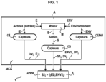
- E1 i , ENV1 i and S1 i are acquired during the flight V i and are associated with each other for each flight V i considered.
- the ACQ acquisition module may be partially or completely embedded on the engine(s) M of the aircraft or on the aircraft.
- the aircraft may be, for example, an airplane or a helicopter.
- the propulsion engine M of the aircraft may be a turbomachine, such as, for example, a turbojet, or others.
- the ACQ acquisition module may comprise first CE sensors for measuring the values E1 i of the input variables E of the engine during the flight V i , and/or second CENV sensors for measuring the values ENV1 i of the environmental variables ENV of the engine M during the flight V i and/or third CS sensors for measuring the values S1 i of the output variables S of the engine M during the flight V i .
- the engine input variables E are control variables on which commands from the aircraft pilot can act to control the engine.
- the engine input variables E may include, for example, a rotational speed of the engine M and/or a pilot command sent to the engine M and/or a control torque of the engine M and/or others.
- the environment variables ENV of the engine M are variables external to the engine M and non-controllable, and may include, for example, an external temperature and/or an external pressure and/or a humidity level and/or a presence of pollution and/or others.
- the output variables S of the engine M are variables resulting from the input variables E and the environment variables ENV and may include, for example, a temperature of the engine M and/or a rotational torque of the rotor of the engine M and/or an instantaneous fuel consumption of the engine M and/or others.
- the acquisition ACQ module can for example record in a memory on board the aircraft, for example in its on-board computer or in a box on board the aircraft, the data DV i of flights V i comprising the values E1 i , ENV1 i and S1 i mentioned above.
- the data DV i of flights V i can be extracted from the ground memory after each flight V i to be sent to the other modules described below of the tracking device 1.
- the tracking device 1 comprises a learning APPR module for generating an individual flight model f i for each flight V i .
- the learning APPR module thus makes it possible to calculate several individual flight models f i for several successive flights V i , V i+1 over time t.
- the index i relates to the flight V i and therefore to the time.
- the learning APPR module is configured to calculate by learning from the data DV i , E1 i , ENV1 i and S1 i of each flight V i the individual flight model f i , linking for this flight V i the input variables E of the engine M, the environment variables ENV of the engine M and the output variables S of the engine M.
- the data DV i , E1 i , ENV1 i and S1 i are learning data of the model f i .
- the model learning APPR module learns the model f i which links the inputs E, the flight ENV variables and the outputs S thanks to the newly acquired data and possibly a part of the past data.
- the part of the past data can be determined by a sliding window in time, or any other device weighting the different data of the previous flights.
- the first values E1 i , ENV1 i , S i of engine input variables E, engine environment variables ENV and engine output variables S are a training data set of the individual flight model f i .
- models f i may be used only on the reference variables, ENV R and E R .
- the tracking device 1 includes a MUT module for using the individual flight models V i , having been calculated by the APPR learning module.
- the reference E R , ENV R values belong to a prescribed set of reference DR data and which are identical for the plurality i of individual flight models f i V i .
- the MUT usage module comprises an ACC access for prescribing or entering the reference DR data.
- the MUT module for using the model f i applies the model f i to a reference DR set of data (flight ENV R variables, input E R variables).
- This reference DR set can be previously stored data, or simulated data.
- This fixed reference DR set can be one or more past flights, or one or more simulated flights, or finally one or more specific points in the validity space of the learned model f i .
- the MUT model use module has as inputs the model f i and the reference DR data and as output estimates of physical quantities.
- the reference DR set makes it possible to compare several learned models f i under different conditions.
- the individual flight model V i uses an algorithm that can be any regression algorithm such as a linear regression, or a Gaussian process, or a linear Gaussian process regression, or a random forest, or a neural network, or a regression by the least squares method or a polynomial regression of order greater than or equal to 2, this algorithm linking the calculated values of the output variables S of the engine M to the values of the input variables E of the engine M and to the environment variables ENV of the engine M.
- the MUT module estimates the reliability of the model, in comparing the training set and the reference DR set, and/or using the training error.
- a possible example of implementation is the use of a regression method providing such an estimate, such as Gaussian processes or any other probabilistic method.
- Another possibility is to use the distance between the two sets, such as the Chamfer distance.
- any estimation technique such as testing the model on a data set not used during training (this set is often called a validation set in the state of the art).
- the individual flight model V i can link the calculated values of the output variables S of the engine M to the values of the input variables E of the engine M and to the environment variables ENV of the engine M.
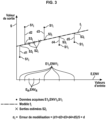
- the MUT usage module is configured to also calculate, for each flight V i , an error ⁇ i associated with the output value estimates S calculated by the individual flight model f i V i . This error ⁇ i is therefore calculated by the MUT usage module from the individual flight model f i V i .
- the MUT module of use is configured to monitor whether the second values S2 i increase then decrease between flights V i-1 , V i , V i+1 and whether the associated error ⁇ i remains low (the associated error ⁇ i remains below a prescribed threshold), in order to, in the affirmative, on both these conditions, automatically trigger an alarm on one or more physical outputs SP for presenting information to a user (display screen and/or others), this alarm indicating that there is a problem on the engine M monitored or on the aircraft having this engine M monitored.
- the tracking device and method according to the invention can make it possible to compare the different models f i with each other, using the models f i on the reference set.
- the tracking device 1 may comprise one or more physical outputs SP for presenting information to a user (display screen and/or others), to provide the engine tracking information INF for the flight Vi.
- this information INF is the torque (S2 i , ⁇ i ).
- the device 1 may comprise a module for automatic tracking of breaks, trends and anomalies in the torque (S2 i , ⁇ i ), implemented by a computer and having as inputs the estimates of physical quantities and the estimates of errors, and as outputs: information INF signaling breaks and/or trends and/or anomalies.
- the user may also use a visual approach, to notice trends, anomalies and breaks, or any automatic algorithm for tracking time series, implemented by a computer.
- a maintenance operation or advice on the use of the monitored M engine may be issued to the customer operating the monitored M engine and/or the aircraft.
- This distance d(E R , E1 i ) can be a distance between sets of points, for example a Hausdorff distance.
- this error ⁇ i can be calculated by assuming that the first values ENV1 i of the environment ENV variables are the same for the different values E1 i and S1 i .
- the individual flight model V i can be a linear regression relating the second output values S2 i to the first values E R , ENV R and relating the third output values S3 i to the first values E1 i , ENV1 i .
- the APPR learning module is configured to calculate by learning, from the first data DV i of each flight V i , an estimate EM of modeling error of the individual flight model f i on the output variables S of the engine M.
- At least some (or all) of the reference E R values and/or at least some (or all) of the reference ENV R values and/or at least some (or all) of the reference S R values are prescribed in association with each other in the prescribed set of reference DR data.
- At least some (or all) of the reference E R values and/or at least some (or all) of the reference ENV R values and/or at least some (or all) of the reference S R values are first flight DV data having been obtained by the acquisition ACQ module for at least one flight V i performed.
- the reference flight(s) V R may be one or more flights V i performed.
- At least some (or all) of the reference E R values and/or at least some (or all) of the reference ENV R values and/or at least some (or all) of the reference S R values are first flight DV data having been simulated for at least one flight V i not actually performed by the aircraft.
- the reference flight(s) V R may be one or more simulated flights V i not actually performed by the aircraft.
- the tracking device 1 makes it possible to implement a method for temporally tracking the state of at least one propulsion engine M of at least one aircraft A, which comprises the steps described below with reference to the figure 6 . These steps are performed automatically by the tracking device 1.
- the DV i data described above are acquired by the ACQ acquisition module.
- the individual flight model f i described above is calculated by the APPR learning module.
- the tracking method may implement one and/or the other of the embodiments described above.
- the tracking device 1 and its APPR, MUT, MTF modules can be implemented by one or more calculators, such as for example one or more computers, or other calculation means.
- the tracking device 1 can comprise a computer program, recorded in a permanent memory thereof, to implement the APPR, MUT, MTF modules and to execute the steps of the tracking method.
Landscapes
- Engineering & Computer Science (AREA)
- Physics & Mathematics (AREA)
- Combustion & Propulsion (AREA)
- Chemical & Material Sciences (AREA)
- Mathematical Physics (AREA)
- General Physics & Mathematics (AREA)
- Automation & Control Theory (AREA)
- Evolutionary Computation (AREA)
- Artificial Intelligence (AREA)
- Mechanical Engineering (AREA)
- General Engineering & Computer Science (AREA)
- Aviation & Aerospace Engineering (AREA)
- Combined Controls Of Internal Combustion Engines (AREA)
- Testing And Monitoring For Control Systems (AREA)
- Testing Of Engines (AREA)
- Management, Administration, Business Operations System, And Electronic Commerce (AREA)
Claims (11)
- Vorrichtung zur zeitlichen Überwachung des Zustands mindestens eines Triebwerks (M) zum Antrieb mindestens eines Luftfahrzeugs (A), wobei die Vorrichtung ein Modul (ACQ) zur Erfassung von Daten (DVi) von Flügen (Vi) des mindestens eines Triebwerks (M) zum Antrieb des mindestens einen Luftfahrzeugs (A), die in Verbindung für jeden Flug (Vi) Werte (E1i) von Eingangsvariablen (E) des Triebwerks während des Fluges (Vi), Werte (ENV1i) von Umgebungsvariablen (ENV) des Triebwerks (M) während des Fluges (Vi) und Werte (S1i) von Ausgangsvariablen (S) des Triebwerks (M) während des Fluges (Vi) aufweisen, ein Lernmodul (APPR), das ausgelegt ist, um durch Lernen ausgehend von den Daten (DVi) jedes Fluges (Vi) ein individuelles Flugmodell (fi) für den Flug (Vi) zu berechnen, das die Eingangsvariablen (E) des Triebwerks (M), die Umgebungsvariablen (ENV) des Triebwerks (M) und die Ausgangsvariablen (S) des Triebwerks (M) verbindet, umfasst,
und gekennzeichnet ist durch aufweisend ein Modul (MUT) zur Verwendung der individuellen Modelle (fi) des Fluges (Vi), das ausgelegt ist, um für jeden Flug (Vi) zu berechnen:
Schätzungen der Werte (S2i=fi(ER, ENVR)) der Ausgangsvariablen (S) des Triebwerks, die durch Anwendung des individuellen Modells (fi) des Fluges (Vi) auf Referenzwerte (ER) der Eingangsvariablen (E) des Triebwerks (M) und auf Referenzwerte (ENVR) der Umgebungsvariablen (ENV) des Triebwerks (M) erhalten werden, und einen Fehler (εi), der den Schätzungen der der Werte (S2i=fi(ER, ENVR)) der Ausgangsvariablen (S) des Triebwerks zugeordnet ist, die durch das individuelle Modell (fi) des Fluges (Vi) erzeugt wurden und die durch Anwendung des individuellen Modells (fi) des Fluges (Vi) auf die Referenzwerte (ER) der Eingangsvariablen (E) des Triebwerks (M) und auf die Referenzwerte (ENVR) der Umgebungsvariablen (ENV) des Triebwerks (M) erhalten wurden, wobei die Referenzwerte (ER, ENVR, SR) zu einem vorgeschriebenen Satz von Referenzdaten (DR) gehören, die für die Mehrzahl (i) der individuellen Modelle (fi) des Fluges (Vi) identisch sind. - Vorrichtung nach Anspruch 1, aufweisend mindestens einen physikalischen Ausgang (SP) zur Darstellung von Informationen für einen Benutzer, um eine Überwachungsinformation (INF) des Triebwerks für den Flug (Vi) bereitzustellen, die durch das Benutzungsmodul (MUT) mindestens ausgehend von den Schätzungen von Werten (S2i=fi(ER, ENVR)) der Ausgangsvariablen (S) des Triebwerks und ausgehend vom Fehler (εi), der diesen Schätzungen und dem individuellen Modell (fi) des Fluges (Vi) zugeordnet ist, bestimmt wird.
- Vorrichtung nach Anspruch 2, wobei die Überwachungsinformation (INF) des Triebwerks für den Flug (Vi) durch das Paar gebildet wird, das aus den Schätzungen der Werte (S2i=fi(ER, ENVR)) der Ausgangsvariablen (S) des Triebwerks und dem Fehler (εi), der den Schätzungen und dem individuellen Modell (fi) des Fluges (Vi) zugeordnet ist, besteht.
- Vorrichtung nach einem beliebigen der vorhergehenden Ansprüche, dadurch gekennzeichnet, dass der Fehler (εi), der den Schätzungen und dem individuellen Modell (fi) des Fluges (Vi) zugeordnet ist, einen berechneten Abstand umfasst, der zwischen den Werten (S1i) der Ausgangsvariablen (S) des Triebwerks (M) und Schätzungen der Werte (S3i) der Ausgangsvariablen (S) des Triebwerks (M) berechnet wurde, die durch das individuelle Modell (fi) des Fluges (Vi) berechnet werden, das auf die Werte (E1i) der Eingangsvariablen (E) des Triebwerks und auf die Werte (ENV1i) der Umgebungsparameter (ENV) des Triebwerks (M) angewendet wird, die den Werten (S1i) der Ausgangsvariablen (S) des Triebwerks (M) zugeordnet sind.
- Vorrichtung nach einem beliebigen der vorhergehenden Ansprüche, dadurch gekennzeichnet, dass der Fehler (εi), der dem individuellen Modell (fi) des Fluges (Vi) zugeordnet ist, einen Abstand umfasst, der zwischen den Referenzwerten (ER) der Eingangsvariablen (E) des Triebwerks (M), die den Referenzwerten (ENVR) der Umgebungsvariablen (ENV) des Triebwerks zugeordnet sind, und den Werten (E1i) der Eingangsvariablen (E) des Triebwerks, die den Werten (ENVi) der Umgebungsvariablen (ENV) des Triebwerks des Fluges (Vi) zugeordnet sind, berechnet wird.
- Vorrichtung nach einem beliebigen der vorhergehenden Ansprüche, dadurch gekennzeichnet, dass das Lernmodul (APPR) ausgelegt ist, um durch Lernen ausgehend von den Daten (DVi) jedes Fluges (Vi) eine Modellierungsfehlerschätzung des individuellen Flugmodells (fi) auf den Ausgangsvariablen (S) des Triebwerks (M) zu berechnen,
wobei der Fehler (εi), der dem individuellen Modell (fi) des Fluges (Vi) zugeordnet ist, die Modellierungsfehlerschätzung des individuellen Flugmodells (fi) umfasst. - Vorrichtung nach einem beliebigen der vorhergehenden Ansprüche, dadurch gekennzeichnet, dass mindestens einige der Referenzwerte (ER) der Referenzeingangsvariablen (E) des Triebwerks (M) und/oder der Referenzwerte (ENVR) der Umgebungsvariablen (ENV) des Triebwerks (M) und/oder der Referenzwerte (SR) der Ausgangsvariablen (S) des Triebwerks (M) in Verbindung miteinander in dem vorgeschriebenen Satz von Referenzdaten (DR) vorgeschrieben sind.
- Vorrichtung nach einem beliebigen der vorhergehenden Ansprüche, dadurch gekennzeichnet, dass mindestens einige der Referenzwerte (ER) der Referenzeingangsvariablen (E) des Triebwerks (M) und/oder der Referenzwerte (ENVR) der Umgebungsvariablen (ENV) des Triebwerks (M) und/oder der Referenzwerte (SR) der Ausgangsvariablen (S) des Triebwerks (M) Flugdaten (DV) sind, die von dem Erfassungsmodul (ACQ) für mindestens einen durchgeführten Flug (Vi) erhalten wurden.
- Vorrichtung nach einem beliebigen der vorhergehenden Ansprüche, dadurch gekennzeichnet, dass mindestens einige der Referenzwerte (ER) der Referenzeingangsvariablen (E) des Triebwerks (M) und/oder der Referenzwerte (ENVR) der Umgebungsvariablen (ENV) des Triebwerks (M) und/oder der Referenzwerte (SR) der Ausgangsvariablen (S) des Triebwerks (M) simulierte Flugdaten (DV) für mindestens einen nicht durchgeführten Flug (Vi) sind.
- Verfahren zur zeitlichen Überwachung des Zustands mindestens eines Triebwerks (M) zum Antrieb mindestens eines Luftfahrzeugs (A), wobei durch ein Erfassungsmodul (ACQ) Daten (DVi) von Flügen (Vi) des mindestens einen Triebwerks (M) zum Antrieb des mindestens einen Luftfahrzeugs (A) erfasst (11) werden, die in Verbindung für jeden Flug (Vi) Werte (E1i) von Eingangsvariablen (E) des Triebwerks während des Fluges (Vi), Werte (ENV1i) von Umgebungsvariablen (ENV) des Triebwerks (M) während des Fluges (Vi) und Werte (S1i) von Ausgangsvariablen (S) des Triebwerks (M) während des Fluges (Vi) aufweisen, durch ein Lernmodul (APPR) ausgehend von den Daten (DVi) jedes Fluges (Vi) ein individuelles Flugmodell (fi) für den Flug (Vi) berechnet (12) wird, das die Eingangsvariablen (E) des Triebwerks (M), die Umgebungsvariablen (ENV) des Triebwerks (M) und die Ausgangsvariablen (S) des Triebwerks (M) verbindet,und dadurch gekennzeichnet, dassdurch ein Modul (MUT) zur Verwendung der individuellen Modelle (fi) des Fluges (Vi) für jeden Flug (Vi) berechnet (13) werden:
Schätzungen der Werte (S2i=fi(ER, ENVR)) der Ausgangsvariablen (S) des Triebwerks, die durch Anwendung des individuellen Modells (fi) des Fluges (Vi) auf Referenzwerte (ER) der Eingangsvariablen (E) des Triebwerks (M) und auf Referenzwerte (ENVR) der Umgebungsvariablen (ENV) des Triebwerks (M), und ein Fehler (εi), der den Schätzungen der Werte (S2i=fi(ER, ENVR)) der Ausgangsvariablen (S) des Triebwerks zugeordnet ist, die durch das individuelle Modell (fi) des Fluges (Vi) erzeugt wurden und die durch Anwendung des individuellen Modells (fi) des Fluges (Vi) auf die Referenzwerte (ER) der Eingangsvariablen (E) des Triebwerks (M) und auf die Referenzwerte (ENVR) der Umgebungsvariablen (ENV) des Triebwerks (M) erhalten wurden, wobei die Referenzwerte (ER, ENVR, SR) zu einem vorgeschriebenen Satz von Referenzdaten (DR) gehören, die für die Mehrzahl (i) der individuellen Modelle (fi) des Fluges (Vi) identisch sind. - Rechnerprogramm, das Codeanweisungen zur Ausführung des Verfahrens zur zeitlichen Überwachung des Zustands von mindestens einem Triebwerk (M) zum Antrieb mindestens eines Flugzeugs nach Anspruch 10 aufweist, wenn es auf einem Rechner des Luftfahrzeugs ausgeführt wird.
Applications Claiming Priority (2)
| Application Number | Priority Date | Filing Date | Title |
|---|---|---|---|
| FR1911082A FR3101669B1 (fr) | 2019-10-07 | 2019-10-07 | Dispositif, procédé et programme d’ordinateur de suivi de moteur d’aéronef |
| PCT/FR2020/051741 WO2021069824A1 (fr) | 2019-10-07 | 2020-10-05 | Dispositif, procédé et programme d'ordinateur de suivi de moteur d'aéronef |
Publications (2)
| Publication Number | Publication Date |
|---|---|
| EP4042007A1 EP4042007A1 (de) | 2022-08-17 |
| EP4042007B1 true EP4042007B1 (de) | 2025-01-01 |
Family
ID=69104736
Family Applications (1)
| Application Number | Title | Priority Date | Filing Date |
|---|---|---|---|
| EP20796633.4A Active EP4042007B1 (de) | 2019-10-07 | 2020-10-05 | Vorrichtung, verfahren und computerprogramm zur überwachung eines flugzeugtriebwerks |
Country Status (4)
| Country | Link |
|---|---|
| US (1) | US11807388B2 (de) |
| EP (1) | EP4042007B1 (de) |
| FR (1) | FR3101669B1 (de) |
| WO (1) | WO2021069824A1 (de) |
Families Citing this family (2)
| Publication number | Priority date | Publication date | Assignee | Title |
|---|---|---|---|---|
| CN113377027A (zh) * | 2021-05-26 | 2021-09-10 | 中国航空工业集团公司沈阳飞机设计研究所 | 一种飞机推进系统试验系统 |
| CN114744824A (zh) * | 2022-05-11 | 2022-07-12 | 星河智源(深圳)科技有限公司 | 可独立控制转速节能环保的智能输出电机 |
Family Cites Families (28)
| Publication number | Priority date | Publication date | Assignee | Title |
|---|---|---|---|---|
| US6216066B1 (en) * | 1998-07-01 | 2001-04-10 | General Electric Company | System and method for generating alerts through multi-variate data assessment |
| US6799154B1 (en) * | 2000-05-25 | 2004-09-28 | General Electric Comapny | System and method for predicting the timing of future service events of a product |
| US6832205B1 (en) * | 2000-06-30 | 2004-12-14 | General Electric Company | System and method for automatically predicting the timing and costs of service events in a life cycle of a product |
| US6466858B1 (en) * | 2000-11-02 | 2002-10-15 | General Electric Company | Methods and apparatus for monitoring gas turbine engine operation |
| US7457732B2 (en) * | 2001-08-17 | 2008-11-25 | General Electric Company | System and method for measuring quality of baseline modeling techniques |
| US7383165B2 (en) * | 2001-08-17 | 2008-06-03 | General Electric Company | System and method for diagnosing faults utilizing baseline modeling techniques |
| US6823675B2 (en) * | 2002-11-13 | 2004-11-30 | General Electric Company | Adaptive model-based control systems and methods for controlling a gas turbine |
| US6962043B2 (en) * | 2003-01-30 | 2005-11-08 | General Electric Company | Method and apparatus for monitoring the performance of a gas turbine system |
| US7734400B2 (en) * | 2003-07-24 | 2010-06-08 | Honeywell International Inc. | Fault detection system and method using augmented data and fuzzy logic |
| US7031812B1 (en) * | 2004-03-15 | 2006-04-18 | Howell Instruments, Inc. | System and method for monitoring aircraft engine health and determining engine power available, and applications thereof |
| US7062370B2 (en) * | 2004-03-30 | 2006-06-13 | Honeywell International Inc. | Model-based detection, diagnosis of turbine engine faults |
| US7487029B2 (en) * | 2004-05-21 | 2009-02-03 | Pratt & Whitney Canada | Method of monitoring gas turbine engine operation |
| JP5043839B2 (ja) * | 2005-07-11 | 2012-10-10 | ブルックス オートメーション インコーポレイテッド | 予知保全用インテリジェント状態監視及び障害診断システム |
| US7286923B2 (en) * | 2005-09-30 | 2007-10-23 | General Electric Company | System and method for estimating turbine engine deterioration rate with noisy data |
| US20090048730A1 (en) * | 2007-08-17 | 2009-02-19 | General Electric Company | Method and system for planning repair of an engine |
| US8165826B2 (en) * | 2008-09-30 | 2012-04-24 | The Boeing Company | Data driven method and system for predicting operational states of mechanical systems |
| US8600917B1 (en) * | 2011-04-18 | 2013-12-03 | The Boeing Company | Coupling time evolution model with empirical regression model to estimate mechanical wear |
| US8720258B2 (en) | 2012-09-28 | 2014-05-13 | United Technologies Corporation | Model based engine inlet condition estimation |
| FR3003032B1 (fr) | 2013-03-07 | 2015-04-03 | Turbomeca | Procede et systeme de controle de la sante d'une turbomachine d'aeronef |
| GB201315654D0 (en) * | 2013-09-03 | 2013-10-16 | Rolls Royce Plc | Operating parameter monitoring method |
| FR3028331B1 (fr) * | 2014-11-10 | 2016-12-30 | Snecma | Procede de surveillance d'un moteur d'aeronef en fonctionnement dans un environnement donne |
| FR3046268B1 (fr) * | 2015-12-23 | 2019-05-10 | Safran Aircraft Engines | Systeme d'exploitation de donnees de vol d'un aeronef |
| FR3052273B1 (fr) * | 2016-06-02 | 2018-07-06 | Airbus | Prediction de pannes dans un aeronef |
| US20180268288A1 (en) * | 2017-03-14 | 2018-09-20 | General Electric Company | Neural Network for Steady-State Performance Approximation |
| US10508597B2 (en) | 2017-04-12 | 2019-12-17 | General Electric Company | Systems and methods for icing detection of compressors |
| US10604278B2 (en) * | 2017-04-18 | 2020-03-31 | General Electric Company | Methods and apparatus to monitor health information of a turbine engine |
| FR3095271B1 (fr) * | 2019-04-18 | 2021-07-30 | Safran | Système de surveillance de la santé d’un hélicoptère |
| FR3095424B1 (fr) * | 2019-04-23 | 2024-10-04 | Safran | Système et procédé de surveillance d’un moteur d’aéronef |
-
2019
- 2019-10-07 FR FR1911082A patent/FR3101669B1/fr active Active
-
2020
- 2020-10-05 WO PCT/FR2020/051741 patent/WO2021069824A1/fr not_active Ceased
- 2020-10-05 EP EP20796633.4A patent/EP4042007B1/de active Active
- 2020-10-05 US US17/765,309 patent/US11807388B2/en active Active
Also Published As
| Publication number | Publication date |
|---|---|
| US11807388B2 (en) | 2023-11-07 |
| FR3101669B1 (fr) | 2022-04-08 |
| US20220371745A1 (en) | 2022-11-24 |
| WO2021069824A1 (fr) | 2021-04-15 |
| FR3101669A1 (fr) | 2021-04-09 |
| EP4042007A1 (de) | 2022-08-17 |
Similar Documents
| Publication | Publication Date | Title |
|---|---|---|
| EP2912526B1 (de) | System zur überwachung einer gruppe von komponenten einer vorrichtung | |
| EP2500267B1 (de) | Überwachung eines Stellglieds zur Flugsteuerung eines Luftfahrzeugs | |
| EP3956646B1 (de) | System zur überwachung des gesundheitszustandes eines hubschraubers | |
| FR2970358A1 (fr) | Pronostic de duree avant maintenance par fusion entre modelisation et simulation, pour equipements electroniques embarques dans un aeronef | |
| EP2966526B1 (de) | Verfahren und system zur zusammenführung von überwachungsindikatoren einer vorrichtung | |
| FR3052273A1 (fr) | Prediction de pannes dans un aeronef | |
| FR2965915A1 (fr) | Systeme de surveillance d'un banc d'essai de moteur d'aeronef | |
| FR3035232A1 (fr) | Systeme de surveillance de l'etat de sante d'un moteur et procede de configuration associe | |
| EP3215903B1 (de) | Werkzeug zur validierung eines systems zur überwachung eines flugzeugtriebwerks | |
| EP0657723A1 (de) | Verfahren und Vorrichtung zum Bestimmen einer Lastdimensionierungsüberschreitung eines Flugzeuges | |
| FR3046268A1 (fr) | Systeme d'exploitation de donnees de vol d'un aeronef | |
| EP4042007B1 (de) | Vorrichtung, verfahren und computerprogramm zur überwachung eines flugzeugtriebwerks | |
| FR3095424A1 (fr) | Système et procédé de surveillance d’un moteur d’aéronef | |
| FR2991486A1 (fr) | Procede et dispositif d'assistance au suivi de mission d'un aeronef | |
| FR2963960A1 (fr) | Surveillance des particules dans un systeme de lubrification | |
| EP4464997B1 (de) | Verfahren und vorrichtung zur überwachung des status eines mechanischen systems eines fahrzeugs unter verwendung von schwellen, die abhängig von den betriebsparametern des systems variieren | |
| EP3489831A1 (de) | Verfahren und vorrichtung zur überwachung eines datenerzeugungsprozesses eines metrischen systems zur vorhersage von störungen | |
| CA2837523A1 (fr) | Systeme de prescription de maintenance d'un moteur d'helicoptere | |
| FR2957170A1 (fr) | Outil de conception d'un systeme de surveillance d'un moteur d'aeronef | |
| EP4559769B1 (de) | Verfahren zur überwachung der temperatur der bremsen eines flugzeugfahrwerks | |
| CA2928844A1 (fr) | Procede et dispositif de gestion de pannes avec un systeme de gestion d'un turbomoteur d'un aeronef | |
| FR3003986A1 (fr) | Procede de detection et de prise en compte d'un changement abrupt d'au moins un indicateur de surveillance d'un dispositif. | |
| FR3113747A1 (fr) | Système électronique pour la mise en œuvre d’une fonction critique et procédé associé | |
| FR2979013A1 (fr) | Systeme de surveillance en banc d'essai de moteur d'aeronef | |
| FR2966878A1 (fr) | Systeme de surveillance d'une chaine de mesure de temperature d'un turboreacteur |
Legal Events
| Date | Code | Title | Description |
|---|---|---|---|
| STAA | Information on the status of an ep patent application or granted ep patent |
Free format text: STATUS: UNKNOWN |
|
| STAA | Information on the status of an ep patent application or granted ep patent |
Free format text: STATUS: THE INTERNATIONAL PUBLICATION HAS BEEN MADE |
|
| PUAI | Public reference made under article 153(3) epc to a published international application that has entered the european phase |
Free format text: ORIGINAL CODE: 0009012 |
|
| STAA | Information on the status of an ep patent application or granted ep patent |
Free format text: STATUS: REQUEST FOR EXAMINATION WAS MADE |
|
| 17P | Request for examination filed |
Effective date: 20220503 |
|
| AK | Designated contracting states |
Kind code of ref document: A1 Designated state(s): AL AT BE BG CH CY CZ DE DK EE ES FI FR GB GR HR HU IE IS IT LI LT LU LV MC MK MT NL NO PL PT RO RS SE SI SK SM TR |
|
| DAV | Request for validation of the european patent (deleted) | ||
| DAX | Request for extension of the european patent (deleted) | ||
| GRAP | Despatch of communication of intention to grant a patent |
Free format text: ORIGINAL CODE: EPIDOSNIGR1 |
|
| STAA | Information on the status of an ep patent application or granted ep patent |
Free format text: STATUS: GRANT OF PATENT IS INTENDED |
|
| RIC1 | Information provided on ipc code assigned before grant |
Ipc: B64D 45/00 20060101ALI20240830BHEP Ipc: G05B 23/02 20060101ALI20240830BHEP Ipc: F02C 9/00 20060101AFI20240830BHEP |
|
| INTG | Intention to grant announced |
Effective date: 20240918 |
|
| GRAS | Grant fee paid |
Free format text: ORIGINAL CODE: EPIDOSNIGR3 |
|
| GRAA | (expected) grant |
Free format text: ORIGINAL CODE: 0009210 |
|
| STAA | Information on the status of an ep patent application or granted ep patent |
Free format text: STATUS: THE PATENT HAS BEEN GRANTED |
|
| AK | Designated contracting states |
Kind code of ref document: B1 Designated state(s): AL AT BE BG CH CY CZ DE DK EE ES FI FR GB GR HR HU IE IS IT LI LT LU LV MC MK MT NL NO PL PT RO RS SE SI SK SM TR |
|
| REG | Reference to a national code |
Ref country code: GB Ref legal event code: FG4D Free format text: NOT ENGLISH |
|
| REG | Reference to a national code |
Ref country code: CH Ref legal event code: EP |
|
| REG | Reference to a national code |
Ref country code: DE Ref legal event code: R096 Ref document number: 602020044119 Country of ref document: DE |
|
| REG | Reference to a national code |
Ref country code: IE Ref legal event code: FG4D Free format text: LANGUAGE OF EP DOCUMENT: FRENCH |
|
| REG | Reference to a national code |
Ref country code: LT Ref legal event code: MG9D |
|
| REG | Reference to a national code |
Ref country code: NL Ref legal event code: MP Effective date: 20250101 |
|
| REG | Reference to a national code |
Ref country code: AT Ref legal event code: MK05 Ref document number: 1756467 Country of ref document: AT Kind code of ref document: T Effective date: 20250101 |
|
| PG25 | Lapsed in a contracting state [announced via postgrant information from national office to epo] |
Ref country code: NL Free format text: LAPSE BECAUSE OF FAILURE TO SUBMIT A TRANSLATION OF THE DESCRIPTION OR TO PAY THE FEE WITHIN THE PRESCRIBED TIME-LIMIT Effective date: 20250101 |
|
| PG25 | Lapsed in a contracting state [announced via postgrant information from national office to epo] |
Ref country code: FI Free format text: LAPSE BECAUSE OF FAILURE TO SUBMIT A TRANSLATION OF THE DESCRIPTION OR TO PAY THE FEE WITHIN THE PRESCRIBED TIME-LIMIT Effective date: 20250101 |
|
| PG25 | Lapsed in a contracting state [announced via postgrant information from national office to epo] |
Ref country code: PL Free format text: LAPSE BECAUSE OF FAILURE TO SUBMIT A TRANSLATION OF THE DESCRIPTION OR TO PAY THE FEE WITHIN THE PRESCRIBED TIME-LIMIT Effective date: 20250101 |
|
| PG25 | Lapsed in a contracting state [announced via postgrant information from national office to epo] |
Ref country code: ES Free format text: LAPSE BECAUSE OF FAILURE TO SUBMIT A TRANSLATION OF THE DESCRIPTION OR TO PAY THE FEE WITHIN THE PRESCRIBED TIME-LIMIT Effective date: 20250101 |
|
| PG25 | Lapsed in a contracting state [announced via postgrant information from national office to epo] |
Ref country code: NO Free format text: LAPSE BECAUSE OF FAILURE TO SUBMIT A TRANSLATION OF THE DESCRIPTION OR TO PAY THE FEE WITHIN THE PRESCRIBED TIME-LIMIT Effective date: 20250401 Ref country code: IS Free format text: LAPSE BECAUSE OF FAILURE TO SUBMIT A TRANSLATION OF THE DESCRIPTION OR TO PAY THE FEE WITHIN THE PRESCRIBED TIME-LIMIT Effective date: 20250501 |
|
| PG25 | Lapsed in a contracting state [announced via postgrant information from national office to epo] |
Ref country code: HR Free format text: LAPSE BECAUSE OF FAILURE TO SUBMIT A TRANSLATION OF THE DESCRIPTION OR TO PAY THE FEE WITHIN THE PRESCRIBED TIME-LIMIT Effective date: 20250101 |
|
| PG25 | Lapsed in a contracting state [announced via postgrant information from national office to epo] |
Ref country code: LV Free format text: LAPSE BECAUSE OF FAILURE TO SUBMIT A TRANSLATION OF THE DESCRIPTION OR TO PAY THE FEE WITHIN THE PRESCRIBED TIME-LIMIT Effective date: 20250101 Ref country code: PT Free format text: LAPSE BECAUSE OF FAILURE TO SUBMIT A TRANSLATION OF THE DESCRIPTION OR TO PAY THE FEE WITHIN THE PRESCRIBED TIME-LIMIT Effective date: 20250502 |
|
| PG25 | Lapsed in a contracting state [announced via postgrant information from national office to epo] |
Ref country code: GR Free format text: LAPSE BECAUSE OF FAILURE TO SUBMIT A TRANSLATION OF THE DESCRIPTION OR TO PAY THE FEE WITHIN THE PRESCRIBED TIME-LIMIT Effective date: 20250402 Ref country code: BG Free format text: LAPSE BECAUSE OF FAILURE TO SUBMIT A TRANSLATION OF THE DESCRIPTION OR TO PAY THE FEE WITHIN THE PRESCRIBED TIME-LIMIT Effective date: 20250101 |
|
| PG25 | Lapsed in a contracting state [announced via postgrant information from national office to epo] |
Ref country code: AT Free format text: LAPSE BECAUSE OF FAILURE TO SUBMIT A TRANSLATION OF THE DESCRIPTION OR TO PAY THE FEE WITHIN THE PRESCRIBED TIME-LIMIT Effective date: 20250101 |
|
| PG25 | Lapsed in a contracting state [announced via postgrant information from national office to epo] |
Ref country code: CZ Free format text: LAPSE BECAUSE OF FAILURE TO SUBMIT A TRANSLATION OF THE DESCRIPTION OR TO PAY THE FEE WITHIN THE PRESCRIBED TIME-LIMIT Effective date: 20250101 |
|
| PG25 | Lapsed in a contracting state [announced via postgrant information from national office to epo] |
Ref country code: SE Free format text: LAPSE BECAUSE OF FAILURE TO SUBMIT A TRANSLATION OF THE DESCRIPTION OR TO PAY THE FEE WITHIN THE PRESCRIBED TIME-LIMIT Effective date: 20250101 |
|
| REG | Reference to a national code |
Ref country code: DE Ref legal event code: R097 Ref document number: 602020044119 Country of ref document: DE |
|
| PG25 | Lapsed in a contracting state [announced via postgrant information from national office to epo] |
Ref country code: SM Free format text: LAPSE BECAUSE OF FAILURE TO SUBMIT A TRANSLATION OF THE DESCRIPTION OR TO PAY THE FEE WITHIN THE PRESCRIBED TIME-LIMIT Effective date: 20250101 |
|
| PG25 | Lapsed in a contracting state [announced via postgrant information from national office to epo] |
Ref country code: DK Free format text: LAPSE BECAUSE OF FAILURE TO SUBMIT A TRANSLATION OF THE DESCRIPTION OR TO PAY THE FEE WITHIN THE PRESCRIBED TIME-LIMIT Effective date: 20250101 |
|
| PG25 | Lapsed in a contracting state [announced via postgrant information from national office to epo] |
Ref country code: IT Free format text: LAPSE BECAUSE OF FAILURE TO SUBMIT A TRANSLATION OF THE DESCRIPTION OR TO PAY THE FEE WITHIN THE PRESCRIBED TIME-LIMIT Effective date: 20250101 |
|
| PG25 | Lapsed in a contracting state [announced via postgrant information from national office to epo] |
Ref country code: EE Free format text: LAPSE BECAUSE OF FAILURE TO SUBMIT A TRANSLATION OF THE DESCRIPTION OR TO PAY THE FEE WITHIN THE PRESCRIBED TIME-LIMIT Effective date: 20250101 |
|
| PG25 | Lapsed in a contracting state [announced via postgrant information from national office to epo] |
Ref country code: RO Free format text: LAPSE BECAUSE OF FAILURE TO SUBMIT A TRANSLATION OF THE DESCRIPTION OR TO PAY THE FEE WITHIN THE PRESCRIBED TIME-LIMIT Effective date: 20250101 |
|
| PG25 | Lapsed in a contracting state [announced via postgrant information from national office to epo] |
Ref country code: SK Free format text: LAPSE BECAUSE OF FAILURE TO SUBMIT A TRANSLATION OF THE DESCRIPTION OR TO PAY THE FEE WITHIN THE PRESCRIBED TIME-LIMIT Effective date: 20250101 |
|
| PLBE | No opposition filed within time limit |
Free format text: ORIGINAL CODE: 0009261 |
|
| STAA | Information on the status of an ep patent application or granted ep patent |
Free format text: STATUS: NO OPPOSITION FILED WITHIN TIME LIMIT |
|
| 26N | No opposition filed |
Effective date: 20251002 |
|
| PGFP | Annual fee paid to national office [announced via postgrant information from national office to epo] |
Ref country code: DE Payment date: 20251020 Year of fee payment: 6 |
|
| PGFP | Annual fee paid to national office [announced via postgrant information from national office to epo] |
Ref country code: GB Payment date: 20251029 Year of fee payment: 6 |
|
| PGFP | Annual fee paid to national office [announced via postgrant information from national office to epo] |
Ref country code: FR Payment date: 20251024 Year of fee payment: 6 |