EP4042023B1 - Séparateur dental - Google Patents
Séparateur dental Download PDFInfo
- Publication number
- EP4042023B1 EP4042023B1 EP20803793.7A EP20803793A EP4042023B1 EP 4042023 B1 EP4042023 B1 EP 4042023B1 EP 20803793 A EP20803793 A EP 20803793A EP 4042023 B1 EP4042023 B1 EP 4042023B1
- Authority
- EP
- European Patent Office
- Prior art keywords
- dental
- zone
- evacuator
- baffle
- housing
- Prior art date
- Legal status (The legal status is an assumption and is not a legal conclusion. Google has not performed a legal analysis and makes no representation as to the accuracy of the status listed.)
- Active
Links
Images


Classifications
-
- F—MECHANICAL ENGINEERING; LIGHTING; HEATING; WEAPONS; BLASTING
- F04—POSITIVE - DISPLACEMENT MACHINES FOR LIQUIDS; PUMPS FOR LIQUIDS OR ELASTIC FLUIDS
- F04F—PUMPING OF FLUID BY DIRECT CONTACT OF ANOTHER FLUID OR BY USING INERTIA OF FLUID TO BE PUMPED; SIPHONS
- F04F5/00—Jet pumps, i.e. devices in which flow is induced by pressure drop caused by velocity of another fluid flow
-
- A—HUMAN NECESSITIES
- A61—MEDICAL OR VETERINARY SCIENCE; HYGIENE
- A61C—DENTISTRY; APPARATUS OR METHODS FOR ORAL OR DENTAL HYGIENE
- A61C17/00—Devices for cleaning, polishing, rinsing or drying teeth, teeth cavities or prostheses; Saliva removers; Dental appliances for receiving spittle
- A61C17/06—Saliva removers; Accessories therefor
- A61C17/065—Saliva removers; Accessories therefor characterised by provisions for processing the collected matter, e.g. for separating solids or air
-
- A—HUMAN NECESSITIES
- A61—MEDICAL OR VETERINARY SCIENCE; HYGIENE
- A61M—DEVICES FOR INTRODUCING MEDIA INTO, OR ONTO, THE BODY; DEVICES FOR TRANSDUCING BODY MEDIA OR FOR TAKING MEDIA FROM THE BODY; DEVICES FOR PRODUCING OR ENDING SLEEP OR STUPOR
- A61M1/00—Suction or pumping devices for medical purposes; Devices for carrying-off, for treatment of, or for carrying-over, body-liquids; Drainage systems
-
- B—PERFORMING OPERATIONS; TRANSPORTING
- B01—PHYSICAL OR CHEMICAL PROCESSES OR APPARATUS IN GENERAL
- B01D—SEPARATION
- B01D21/00—Separation of suspended solid particles from liquids by sedimentation
-
- B—PERFORMING OPERATIONS; TRANSPORTING
- B01—PHYSICAL OR CHEMICAL PROCESSES OR APPARATUS IN GENERAL
- B01D—SEPARATION
- B01D21/00—Separation of suspended solid particles from liquids by sedimentation
- B01D21/0039—Settling tanks provided with contact surfaces, e.g. baffles, particles
-
- F—MECHANICAL ENGINEERING; LIGHTING; HEATING; WEAPONS; BLASTING
- F04—POSITIVE - DISPLACEMENT MACHINES FOR LIQUIDS; PUMPS FOR LIQUIDS OR ELASTIC FLUIDS
- F04F—PUMPING OF FLUID BY DIRECT CONTACT OF ANOTHER FLUID OR BY USING INERTIA OF FLUID TO BE PUMPED; SIPHONS
- F04F5/00—Jet pumps, i.e. devices in which flow is induced by pressure drop caused by velocity of another fluid flow
- F04F5/14—Jet pumps, i.e. devices in which flow is induced by pressure drop caused by velocity of another fluid flow the inducing fluid being elastic fluid
- F04F5/24—Jet pumps, i.e. devices in which flow is induced by pressure drop caused by velocity of another fluid flow the inducing fluid being elastic fluid displacing liquids, e.g. containing solids, or liquids and elastic fluids
Definitions
- the invention relates to a dental separator for the dental treatment area.
- a dental separator is a typically compact component that is used in dental treatment stations to separate solid particles from the air-liquid mixture that is sucked out of a patient's mouth.
- a known construction of a dental separator is shown, for example, in WO 2000/071050 A1 presented. From the US 5,018,971 A and US 5,613,851 A Examples of dental separators are also known.
- Dental separators with jet pumps are used in the US 6,276,936 B1 , WO 95/12365 A1 , EP 2 977 613 A1 and DE 20 2010 010 802 U1 disclosed. Further examples of dental separators, which, however, do not have a jet pump, are shown here US 2018/289457 A1 and FR 2 622 566 A1 .
- the object of the invention is to provide a dental separator which achieves improved separation between air and particle-laden liquid.
- the invention relates to a dental separator with a housing, in the upper region of which a dewatering zone for separating particle-containing liquid from an air stream loaded with the liquid is formed, the housing having an inlet for the loaded air stream which opens tangentially into the dewatering zone , and a separation zone for separating the particles from the particle-containing liquid is formed in the housing below the drainage zone, which sinks from the drainage zone into the separation zone.
- the dewatering zone comprises a curved flow path and the inlet has a jet pump with a propellant media connection for a propellant medium, a suction media connection for a suction medium and an outlet, the outlet opening tangentially into the flow path.
- the jet pump includes a Venturi nozzle in which the propellant medium is forced through a restriction at high pressure in order to generate a negative pressure there. Due to this negative pressure, a suction medium is sucked in through the suction medium connection, which opens into the nozzle in the area of the narrowing, and mixed with the propellant medium.
- the jet pump is characterized by its simple structure and high operational reliability.
- the jet pump is installed in the dental treatment unit as an air jet pump.
- compressed air flows through the Venturi nozzle.
- the resulting suction is used for suction.
- a saliva ejector can be connected to the suction media connection and a compressed air source can be connected to the driving media connection.
- the compressed air source is unlocked and the compressed air flows through the nozzle to create a negative pressure on the saliva ejector.
- the air-saliva mixture with dispersed solid particles sucked in by the saliva ejector is then mixed with the compressed air in the nozzle and enters the annular flow path at high speed.
- the compressed air source can be, for example, a pressurized gas bottle, with a controllable valve being arranged between the gas bottle and the jet pump in order to be able to selectively activate the jet pump.
- a pump such as an air pump, which can be activated selectively, can also be used.
- the housing is preferably round in cross section and runs along an axis that is essentially vertical in the installation situation.
- the inlet is at the top of the housing.
- An outlet or outlets for the dewatered air flow or the ultimately particle-free liquid are located at the bottom of the housing.
- the housing can consist of several parts.
- the housing can comprise a lower housing part and an upper housing part placed thereon, it being preferred that the lower housing part is closed at its bottom and open at the top, and that the upper housing part is closed at the top using a lid and a Has a floor that divides the interior of the housing into a drainage zone and a separation zone.
- the inlet is preferably located on the upper part of the housing.
- the inlet preferably opens tangentially into the flow path.
- the flow path can run inwards in a helical manner by almost a full revolution until it ends at an outlet.
- the baffle plates are distributed evenly and all at the same height over the extent of the flow channel and are inclined upwards from the horizontal in the flow direction at an acute angle of, for example, 10°-40° or preferably 20°-30°.
- a curvature of the baffle plates in the direction of flow can also be provided.
- the distance visible in the plan view between the front edges and rear edges of successive baffle leaves is preferably smaller than half the circumferential extent and preferably smaller than a quarter of the circumferential extent of the baffle leaves. Further preferably, the front edges and trailing edges of successive baffle blades are aligned or the baffle blades even overlap.
- a design corresponding to one or more of the preferred embodiments described above results in an overall step-shaped contour of the baffle leaves.
- This contour means that the air flow in the flow path is hardly swirled by the baffle leaves and that air movement in the separation zone below the baffle ring is effectively prevented. In this way, agitation of the liquid collected there can be avoided and sedimentation of the particles contained in the liquid can be promoted. Nevertheless, the air flow is effectively drained.
- the baffle plates can protrude radially from a curved wall within the housing, which defines the inside of the flow path.
- web-like guide projections which protrude into the flow channel are provided on a wall which forms the outer boundary of the flow channel and which can be the wall of an insert inserted in the housing or a wall of the housing jacket.
- the guide projections can have the shape of webs that are inclined backwards from the vertical at an acute angle of, for example, between 5° and 30° and are slightly convexly curved.
- the lower ends of the guide projections can rest on the top of a corresponding baffle plate. It is preferably provided that, in one embodiment variant, a gap can be formed between the outer edge of the baffle leaves and the inner surface of a wall, which forms the outer boundary of the flow channel. The gap should connect to the point of contact in the direction of drainage, i.e. against the direction of flow, so that water separated on the guide projection can run down.
- the boundary walls of the flow channel together with baffle contours, i.e. baffle plates and possibly guide projections, can be formed on an insert which is accommodated in the housing and preferably in the upper housing part.
- the insert can be manufactured overall as an injection molded part.
- a collecting zone in the form of, for example, a groove curved around the axis of the dental separator in order to collect the water separated from the air flow at the baffle contours. From this collection zone, the water can be led into the separation zone through, for example, a downpipe.
- a sedimentation zone is formed, which is delimited at the top by means of a filter in the form of at least one sieve tray and optionally one or more fills, the sieve trays and optionally fills depleting suspended particles from the water.
- a suction area can be formed above the filter medium.
- the housing further includes an outlet for the treated air stream located at the distal end of the curved flow path Drainage zone leads to the outside.
- the outlet is accordingly arranged in the upper area of the housing, for example on the upper housing part.
- a Venturi nozzle with a constriction can be formed within the outlet, into which a suction pipe leading from the suction area of the separation zone opens. Due to the air flow, the outlet designed in this way acts as an air jet pump, with which the cleaned liquid can be sucked out of the dewatering zone and directed outwards together with the previously dewatered air flow.
- the invention further relates to a dental treatment unit comprising a saliva ejector, a pressure source and a dental separator according to the invention, the saliva ejector being connected to the suction media connection and a pressure source being connected to the driving media connection.
- a dental treatment unit comprising a saliva ejector, a pressure source and a dental separator according to the invention, the saliva ejector being connected to the suction media connection and a pressure source being connected to the driving media connection.
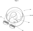
- the separator 200 according to the invention shown in Figures 9 comprises a housing made of plastic with a round cross-section, which in this case is composed of a lower housing part 210 and an upper housing part 220.
- the lower housing part 210 is closed at its bottom and open at the top.
- the upper housing part 220 is also open at the top, being closed at the top by a cover 220a.
- the bottom 268 of the upper housing part 220 which delimits the interior of the upper housing part 220 from the interior of the lower housing part 210, will be described in more detail below.
- the housing encloses a multi-part interior, with an air guide insert 260 being inserted in the area of the upper housing part 220, which defines a drainage space 221 that runs inwards in a helical manner by almost a full revolution.
- the air guide insert 260 is adjoined by a sedimentation area described in more detail below.
- the air-liquid mixture coming from the saliva ejector is introduced tangentially into the drainage space 221 via the inlet connection 222 arranged on the upper housing part 220 and guided all around via a special cascade-shaped unit, which will be described in more detail below.
- the particle-containing liquid i.e. the particle-containing water-saliva mixture, is separated from the stream by centrifugal forces and collisions of the air flow with baffles.
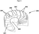
- the baffles include, on the one hand, web-like guide projections 262 on the outer surface 263 of the air guide insert 260, which delimits the helical drainage space 221 to the outside.
- the guide projections 262 have the shape of webs that are slightly inclined from the vertical and are slightly convexly curved, the inclination with respect to the flow direction being such that the webs are slightly at the bottom are inclined backwards and the curvature is convex with respect to the direction of flow.
- the impact projections include a ring of radial blades 264, which extend from the inner lateral surface 265 of the air guide insert 260, which delimits the helical drainage space 221 inwards, to the outer lateral surface 263 and delimit the drainage space 221 downwards.
- the leaflets 264 are distributed evenly and all at the same height over the circumference of the inner lateral surface 265 or over the extent of the helical drainage space 221.
- the leaves 264 are inclined from the horizontal at an acute angle of approximately 20°-30° so that they form slightly inclined impact contours for the air flow in the drainage space 221. Since the leaflets 264 are also at a short distance from one another, with the front edge of each leaflet 264 ending at the rear edge of the subsequent leaflet 264, a step-shaped contour results.
- the lower ends of the guide projections 262 rest on the surface of a corresponding leaflet 264, with the point of contact being followed by a gap 266 formed between the leaflet 264 and the outer jacket 263, through which water deposited on the guide projection 262 drains downwards out of the drainage space 221 can. The water is guided into this gap 266 through the contour of the guide projections 262.
- Water can also escape downwards from the drainage space 221 through the spaces between the leaves 264 or steps.
- the dewatered air flow is directed at the end of the drainage space 221 through an outlet port 228, with a constriction being arranged in the outlet port 228 at which the emerging air creates a negative pressure due to the Venturi effect generated.
- a suction pipe 229 which is immersed in the lower housing part, opens into this negative pressure area for sucking in purified water. This process will be described later.
- the particle-containing liquid separated from the air-liquid mixture in the drainage space 221 flows along a slightly inclined path 267 on the bottom 268 of the upper housing part 220 through an opening 269 into a downpipe 211 arranged centrally in the lower housing part 210 into a first sedimentation zone 212 on the floor the lower housing part 210.
- the liquid driven by the liquid coming in the downpipe 211, rises upwards in an annular rising zone 213, which is delimited on the outside by the jacket of the lower housing part 210 and on the inside by the downpipe 211.
- a sieve plate 251 is inserted in the rising zone 213, through which the liquid passes on its way up.
- Various fillings which are not shown in the figures, are applied to the sieve base 251. Individual beds can also be separated from each other via floors. The water rises with the particles into this bed or beds, with the heavier particles already sedimenting in the first sedimentation zone 212 and the suspended particles remaining in the beds.
- the fills can consist of different materials such as activated carbon, zinc shavings, coarse-pored zeolite or other materials, with the respective layers having different grain sizes. It may be preferable to provide a coarser grain in the lower layers and to provide increasingly finer grains towards the top in order to achieve a classification of the separated particles and to collect the smallest suspended particles in the finest layer at the top.
- cascade-shaped staircase structure which is formed in the drainage space 221 by the leaves 264, as well as the guide projections 262.
- the shown construction of the separator 200 according to this embodiment variant ensures in a very advantageous manner that the water passes through a rest zone as it slowly rises into the various layers and is not swirled in the apparatus. Only after passing through the various layers is it then sucked off the surface through the suction pipe 229. However, the water underneath is at rest, so that sedimentation or the collection of suspended particles can be carried out optimally here. The entrainment of suspended particles, even of very small grain sizes, is effectively avoided.
- the housing is made of plastic and is simply put together in several parts.
- the air guide insert 260 is designed as a separate injection molded part and is easily inserted into the upper housing part 220.
- the separator 200 fills with suspended particles during use, which usually consist of amalgam and other substances from dental treatment, when the maximum capacity is reached, the entire housing can be closed with special screw caps and transported as a whole for further processing.
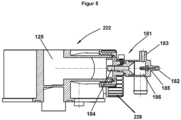
- a special feature of the present dental separator lies in the design of the inlet connection 222, as shown in Figure 5 can be recognized.
- the core of the jet pump 181 is a Venturi nozzle 185, through which pressurized air is driven to generate a negative pressure in a mixing chamber 186. Due to this negative pressure, an air-saliva mixture is sucked in by a saliva ejector through the suction media connection 182, which opens into the mixing chamber 186, and mixed with the compressed air from the propulsion media connection 182.
- the resulting air-saliva mixture flows at high speed through the outlet 184 into the flow path and takes the course already described above.
- the design of the impact contours described in the exemplary embodiment is particularly advantageous at the high media speeds that result from the design of the inlet connection 222 according to the invention and from the use of compressed air as a driving medium, since it allows very good air guidance even at high media speeds.
Landscapes
- Health & Medical Sciences (AREA)
- Engineering & Computer Science (AREA)
- Veterinary Medicine (AREA)
- Public Health (AREA)
- General Health & Medical Sciences (AREA)
- Animal Behavior & Ethology (AREA)
- Life Sciences & Earth Sciences (AREA)
- Chemical & Material Sciences (AREA)
- Fluid Mechanics (AREA)
- Epidemiology (AREA)
- Dentistry (AREA)
- Heart & Thoracic Surgery (AREA)
- Mechanical Engineering (AREA)
- Chemical Kinetics & Catalysis (AREA)
- Physics & Mathematics (AREA)
- General Engineering & Computer Science (AREA)
- Hematology (AREA)
- Biomedical Technology (AREA)
- Anesthesiology (AREA)
- Vascular Medicine (AREA)
- Dental Tools And Instruments Or Auxiliary Dental Instruments (AREA)
Claims (15)
- Séparateur dentaire (200) avec un boîtier, dans la région supérieure duquel est réalisée une zone de déshydratation (221) pour séparer un liquide contenant des particules d'un courant d'air chargé du liquide, le boîtier présentant une entrée (222) pour le courant d'air chargé, qui débouche tangentiellement dans la zone de déshydratation (221), et une zone de séparation étant réalisée dans le boîtier sous la zone de déshydratation (221) pour séparer les particules du liquide contenant des particules qui descend de la zone de déshydratation (221) dans la zone de séparation,
caractérisé en ce que
la zone de déshydratation (221) comprend une voie d'écoulement incurvée et l'entrée (222) présente une pompe à jet (181) avec un raccord de milieu de propulsion (182) pour un milieu de propulsion, un raccord de milieu d'aspiration (183) pour un milieu d'aspiration et une sortie (184), la sortie (184) débouchant tangentiellement dans la voie d'écoulement. - Séparateur dentaire (200) selon la revendication 1, caractérisé en ce que la zone de déshydratation (221) comprend une voie d'écoulement incurvée qui est délimitée sur son côté inférieur par une couronne de lamelles déflectrices (264).
- Séparateur dentaire (200) selon la revendication 2, caractérisé en ce que les lamelles déflectrices (264) sont réparties uniformément et/ou toutes à la même hauteur sur l'étendue du canal d'écoulement et/ou en ce que les lamelles déflectrices (264) sont inclinées vers le haut par rapport à l'horizontale selon un angle aigu de préférence de 10° à 40° et encore de préférence de 20° à 30° dans la direction d'écoulement.
- Séparateur dentaire (200) selon la revendication 2 ou 3, caractérisé en ce que la distance perceptible en vue de dessus entre les bords avant et les bords arrière de lamelles déflectrices successives (264) est inférieure à la moitié de l'étendue circonférentielle et de préférence inférieure à un quart de l'étendue circonférentielle des lamelles déflectrices (264).
- Séparateur dentaire (200) selon l'une quelconque des revendications 2 à 4, caractérisé en ce que les lamelles déflectrices (264) partent radialement à l'intérieur du boîtier à partir d'une paroi incurvée, qui définit le côté intérieur de la voie d'écoulement.
- Séparateur dentaire (200) selon l'une quelconque des revendications 2 à 5, caractérisé en ce que des protubérances de guidage (262) de type nervures qui font saillie dans le canal d'écoulement sont prévues sur une paroi (263) qui forme la délimitation extérieure du canal d'écoulement, il étant de préférence prévu que les extrémités inférieures des protubérances de guidage (262) reposent sur le côté supérieur d'une lamelle déflectrice (264) correspondante, il étant encore de préférence prévu qu'entre le bord extérieur de la lamelle déflectrice (264) et la surface intérieure de la paroi qui forme la délimitation extérieure du canal d'écoulement, il est réalisé respectivement une fente (266) qui se raccorde au point de contact dans la direction du flux sortant sur le côté supérieur de la lamelle déflectrice (264).
- Séparateur dentaire (200) selon l'une quelconque des revendications 2 à 6, caractérisé en ce que les parois de délimitation du canal d'écoulement ainsi que les lamelles déflectrices (264) sont réalisées sur un insert qui est logé dans le boîtier et de préférence dans la partie de boîtier supérieure (220).
- Séparateur dentaire (200) selon l'une quelconque des revendications 2 à 7, caractérisé en ce qu'une zone de collecte est prévue sous la couronne de lamelles déflectrices (264) pour collecter l'eau séparée du courant d'air au niveau des contours déflecteurs.
- Séparateur dentaire (200) selon l'une quelconque des revendications précédentes, caractérisé en ce qu'une zone de sédimentation (212) est réalisée dans la région de fond du boîtier, qui est délimitée vers le haut par un filtre (251) par rapport à une région d'aspiration.
- Séparateur dentaire (200) selon l'une quelconque des revendications précédentes, caractérisé en ce que le boîtier présente en outre une sortie (228) pour le courant d'air traité, qui, à l'extrémité distale de la voie d'écoulement incurvée, mène de la zone de déshydratation (221) vers l'extérieur.
- Séparateur dentaire (200) selon les revendications 9 et 10, caractérisé en ce qu'à l'intérieur de la sortie (228) est réalisée une buse Venturi (185) avec un rétrécissement dans lequel débouche un tube d'aspiration (229) menant hors de la région d'aspiration de la zone de séparation.
- Unité de traitement dentaire comprenant un aspirateur de salive, une source de pression et un séparateur dentaire (200) selon l'une quelconque des revendications précédentes, l'aspirateur de salive étant relié au raccord de milieu d'aspiration (183) et une source de pression étant reliée au raccord de milieu de propulsion (182).
- Unité de traitement dentaire selon la revendication 12, caractérisée en ce que la source de pression consiste en une bouteille de gaz sous pression, de préférence remplie d'air comprimé, une soupape commandable étant de préférence agencée entre la bouteille de gaz et la pompe à jet (181) afin de pouvoir activer sélectivement la pompe à jet (181).
- Unité de traitement dentaire selon la revendication 13, caractérisée en ce qu'une soupape commandable est agencée entre la bouteille de gaz et la pompe à jet (181).
- Unité de traitement dentaire selon la revendication 13, caractérisée en ce que la source de pression consiste en une pompe, de préférence une pompe à air.
Applications Claiming Priority (2)
| Application Number | Priority Date | Filing Date | Title |
|---|---|---|---|
| ATA50954/2019A AT523130B1 (de) | 2019-11-08 | 2019-11-08 | Dentalabscheider |
| PCT/EP2020/081274 WO2021089773A1 (fr) | 2019-11-08 | 2020-11-06 | Évacuateur dentaire |
Publications (3)
| Publication Number | Publication Date |
|---|---|
| EP4042023A1 EP4042023A1 (fr) | 2022-08-17 |
| EP4042023C0 EP4042023C0 (fr) | 2024-01-03 |
| EP4042023B1 true EP4042023B1 (fr) | 2024-01-03 |
Family
ID=73198295
Family Applications (1)
| Application Number | Title | Priority Date | Filing Date |
|---|---|---|---|
| EP20803793.7A Active EP4042023B1 (fr) | 2019-11-08 | 2020-11-06 | Séparateur dental |
Country Status (5)
| Country | Link |
|---|---|
| EP (1) | EP4042023B1 (fr) |
| CN (1) | CN114729650B (fr) |
| AT (1) | AT523130B1 (fr) |
| BR (1) | BR112022008054A2 (fr) |
| WO (1) | WO2021089773A1 (fr) |
Family Cites Families (24)
| Publication number | Priority date | Publication date | Assignee | Title |
|---|---|---|---|---|
| US3485246A (en) * | 1966-07-05 | 1969-12-23 | George K Austin Jr | Aspirator device |
| DE3248471A1 (de) * | 1982-12-29 | 1984-07-05 | Robert Krups Stiftung & Co KG, 5650 Solingen | Zahn- und mundpflegeeinrichtung |
| DE3542134A1 (de) * | 1985-11-28 | 1987-06-04 | Duerr Dental Gmbh Co Kg | Geraet zum abscheiden feiner feststoffpartikel aus abwasser |
| DE8702001U1 (de) * | 1987-02-10 | 1987-03-26 | Pregenzer, Bruno, Oberperfuß | Abscheider |
| CH675549A5 (fr) * | 1987-10-31 | 1990-10-15 | Emda | |
| AT395941B (de) * | 1991-04-12 | 1993-04-26 | Trawoeger Werner | Abscheider zur trennung eines feststoff-fluessigkeitsgemisches |
| AT400393B (de) * | 1993-11-05 | 1995-12-27 | Trawoeger Werner | Abscheider |
| DE4340193B4 (de) * | 1993-11-25 | 2004-02-26 | Dürr Dental GmbH & Co. KG | Saugeinheit für dentale Zwecke |
| US6276936B1 (en) * | 1999-09-30 | 2001-08-21 | Michael Forster | Dental separator for solids from a solids/liquid mixture |
| ATE278364T1 (de) | 1999-05-20 | 2004-10-15 | Bruno Pregenzer | Abscheider zur abtrennung von feststoffen aus einem an einem zahnärztlichen behandlungsplatz anfallenden flüssigkeits-feststoffgemisch |
| US20050089408A1 (en) * | 2003-05-09 | 2005-04-28 | Solomon Jason D. | Fluid ejector pumps |
| EP1516594A1 (fr) * | 2003-09-18 | 2005-03-23 | Dentalman A/S | Système d'aspiration unitaire dentaire portable |
| DE102006014682B4 (de) * | 2006-03-28 | 2017-02-02 | DüRR DENTAL AG | Saugmaschine |
| DE102006058955B4 (de) * | 2006-12-12 | 2014-07-24 | DüRR DENTAL AG | Saugvorrichtung für dentale, medizinische und industrielle Zwecke |
| DE202010010802U1 (de) * | 2010-07-29 | 2011-11-02 | DüRR DENTAL AG | Feststoffabscheider |
| AT510883B1 (de) * | 2010-12-20 | 2013-03-15 | Alfred Konzett | Abscheider zum abscheiden von feststoffen aus einem zahnärztlichen abwassergemisch |
| CN103041461B (zh) * | 2013-01-09 | 2015-05-13 | 江苏岱洛医疗科技有限公司 | 医用抽吸装置 |
| US9687760B2 (en) * | 2013-05-06 | 2017-06-27 | Gregory S. Antoun | Separation devices, systems and methods for separation of particulates from liquid |
| US10342647B2 (en) * | 2013-10-22 | 2019-07-09 | Crosstex International, Inc. | Apparatus and method for removing amalgam and waste particles from dental office suction effluent |
| EP2977613A1 (fr) * | 2014-07-25 | 2016-01-27 | BPR Swiss GmbH | Dispositif d'aspiration à des fins médicales et industrielles |
| DE102014221203A1 (de) * | 2014-10-20 | 2016-05-04 | Ksb Aktiengesellschaft | Strahlpumpe |
| CN204337070U (zh) * | 2014-12-12 | 2015-05-20 | 上海森徳科技发展有限公司 | 静音正压吸唾系统 |
| WO2017015045A1 (fr) * | 2015-07-17 | 2017-01-26 | Dayco Ip Holdings, Llc | Dispositifs pour produire un vide à l'aide de l'effet venturi ayant une pluralité de sous-voies de passage et de sorties motrices dans la section motrice |
| US10359055B2 (en) * | 2017-02-10 | 2019-07-23 | Carnot Compression, Llc | Energy recovery-recycling turbine integrated with a capillary tube gas compressor |
-
2019
- 2019-11-08 AT ATA50954/2019A patent/AT523130B1/de active
-
2020
- 2020-11-06 EP EP20803793.7A patent/EP4042023B1/fr active Active
- 2020-11-06 CN CN202080078053.9A patent/CN114729650B/zh active Active
- 2020-11-06 BR BR112022008054A patent/BR112022008054A2/pt unknown
- 2020-11-06 WO PCT/EP2020/081274 patent/WO2021089773A1/fr not_active Ceased
Also Published As
| Publication number | Publication date |
|---|---|
| EP4042023C0 (fr) | 2024-01-03 |
| CN114729650B (zh) | 2024-05-24 |
| WO2021089773A1 (fr) | 2021-05-14 |
| AT523130A1 (de) | 2021-05-15 |
| BR112022008054A2 (pt) | 2022-07-12 |
| EP4042023A1 (fr) | 2022-08-17 |
| CN114729650A (zh) | 2022-07-08 |
| AT523130B1 (de) | 2022-10-15 |
Similar Documents
| Publication | Publication Date | Title |
|---|---|---|
| EP1062047B1 (fr) | Separateur cyclone | |
| EP0649346B1 (fr) | Dispositif pour le chargement central de bassins circulaires | |
| DE112012001826B4 (de) | Filter | |
| EP0400431B1 (fr) | Dispositif séparateur | |
| CH669742A5 (fr) | ||
| WO2012013292A1 (fr) | Séparateur de solides | |
| EP2558181A1 (fr) | Cartouche filtrante, en particulier pour le nettoyage des eaux résiduaires dentaires | |
| EP2422862B1 (fr) | Séparateur pour la séparation d'un mélange à une ou plusieurs phases | |
| DE112018004424T5 (de) | Austragsverarbeitungseinrichtung für ein Fahrzeugdruckluftbremsenfüllsystem | |
| DE68905234T2 (de) | Rundfilter mit filtereinsatz. | |
| EP4042023B1 (fr) | Séparateur dental | |
| DE69116513T2 (de) | Sortiervorrichtung zum Entfernen von Knoten aus einer flüssigen Suspension von Fasern und Knoten | |
| DE10393196T5 (de) | Zentrifugalabscheider | |
| DE2256678A1 (de) | Fliehkraftabscheider | |
| EP4041123B1 (fr) | Separateur dental | |
| DE3034400A1 (de) | Fliehkraftabscheider zur abscheidung von schmutzteilchen und fluessigkeiten aus einem gasstrom | |
| DE10217967C1 (de) | Filtervorrichtung zur Filterung von Fluiden | |
| DE69936605T2 (de) | Eine Abscheider-Zentrifuge | |
| DE4318522A1 (de) | Vorrichtung zur zentrischen Beschickung von Becken wie Rundsandfängen, Sandklassierern oder Absetzbecken in Rundbauweise | |
| DE19738912A1 (de) | Vorrichtung und Verfahren zum Abscheiden von Feststoffen aus einem Trägerstrom sowie deren Verwendung | |
| DE2430162C3 (de) | An ein Auftrags- und Aufnahmegerät für eine Reinigungsflüssigkeit zur Naßbzw. Feuchtreinigung oder an ähnliche Geräte anschlieBbare Vorrichtung zum Ansaugen eines Mehrstoffgemisches, zum Trennen und Fördern der festen, flüssigen und gasförmigen Komponenten des Mehrstoffgemisches sowie Zurückgewinnen und Bereitstellen der flüssigen Komponente | |
| AT402817B (de) | Sedimentationsbecken, speziell für kreislaufsysteme | |
| DE10317772A1 (de) | Staubabscheider | |
| DE4330458A1 (de) | Vorrichtung zum Entfernen von Flüssigkeit aus einem Luft-Flüssigkeits-Separator | |
| DE3040848A1 (de) | Strahlpumpe |
Legal Events
| Date | Code | Title | Description |
|---|---|---|---|
| STAA | Information on the status of an ep patent application or granted ep patent |
Free format text: STATUS: UNKNOWN |
|
| STAA | Information on the status of an ep patent application or granted ep patent |
Free format text: STATUS: THE INTERNATIONAL PUBLICATION HAS BEEN MADE |
|
| PUAI | Public reference made under article 153(3) epc to a published international application that has entered the european phase |
Free format text: ORIGINAL CODE: 0009012 |
|
| STAA | Information on the status of an ep patent application or granted ep patent |
Free format text: STATUS: REQUEST FOR EXAMINATION WAS MADE |
|
| 17P | Request for examination filed |
Effective date: 20220511 |
|
| AK | Designated contracting states |
Kind code of ref document: A1 Designated state(s): AL AT BE BG CH CY CZ DE DK EE ES FI FR GB GR HR HU IE IS IT LI LT LU LV MC MK MT NL NO PL PT RO RS SE SI SK SM TR |
|
| DAV | Request for validation of the european patent (deleted) | ||
| DAX | Request for extension of the european patent (deleted) | ||
| GRAP | Despatch of communication of intention to grant a patent |
Free format text: ORIGINAL CODE: EPIDOSNIGR1 |
|
| STAA | Information on the status of an ep patent application or granted ep patent |
Free format text: STATUS: GRANT OF PATENT IS INTENDED |
|
| INTG | Intention to grant announced |
Effective date: 20230609 |
|
| GRAS | Grant fee paid |
Free format text: ORIGINAL CODE: EPIDOSNIGR3 |
|
| GRAA | (expected) grant |
Free format text: ORIGINAL CODE: 0009210 |
|
| STAA | Information on the status of an ep patent application or granted ep patent |
Free format text: STATUS: THE PATENT HAS BEEN GRANTED |
|
| AK | Designated contracting states |
Kind code of ref document: B1 Designated state(s): AL AT BE BG CH CY CZ DE DK EE ES FI FR GB GR HR HU IE IS IT LI LT LU LV MC MK MT NL NO PL PT RO RS SE SI SK SM TR |
|
| REG | Reference to a national code |
Ref country code: GB Ref legal event code: FG4D Free format text: NOT ENGLISH |
|
| REG | Reference to a national code |
Ref country code: DE Ref legal event code: R096 Ref document number: 502020006637 Country of ref document: DE |
|
| REG | Reference to a national code |
Ref country code: CH Ref legal event code: EP |
|
| REG | Reference to a national code |
Ref country code: IE Ref legal event code: FG4D Free format text: LANGUAGE OF EP DOCUMENT: GERMAN |
|
| U01 | Request for unitary effect filed |
Effective date: 20240103 |
|
| U07 | Unitary effect registered |
Designated state(s): AT BE BG DE DK EE FI FR IT LT LU LV MT NL PT SE SI Effective date: 20240108 |
|
| PG25 | Lapsed in a contracting state [announced via postgrant information from national office to epo] |
Ref country code: ES Free format text: LAPSE BECAUSE OF FAILURE TO SUBMIT A TRANSLATION OF THE DESCRIPTION OR TO PAY THE FEE WITHIN THE PRESCRIBED TIME-LIMIT Effective date: 20240103 |
|
| PG25 | Lapsed in a contracting state [announced via postgrant information from national office to epo] |
Ref country code: ES Free format text: LAPSE BECAUSE OF FAILURE TO SUBMIT A TRANSLATION OF THE DESCRIPTION OR TO PAY THE FEE WITHIN THE PRESCRIBED TIME-LIMIT Effective date: 20240103 |
|
| PG25 | Lapsed in a contracting state [announced via postgrant information from national office to epo] |
Ref country code: IS Free format text: LAPSE BECAUSE OF FAILURE TO SUBMIT A TRANSLATION OF THE DESCRIPTION OR TO PAY THE FEE WITHIN THE PRESCRIBED TIME-LIMIT Effective date: 20240503 |
|
| PG25 | Lapsed in a contracting state [announced via postgrant information from national office to epo] |
Ref country code: GR Free format text: LAPSE BECAUSE OF FAILURE TO SUBMIT A TRANSLATION OF THE DESCRIPTION OR TO PAY THE FEE WITHIN THE PRESCRIBED TIME-LIMIT Effective date: 20240404 |
|
| PG25 | Lapsed in a contracting state [announced via postgrant information from national office to epo] |
Ref country code: RS Free format text: LAPSE BECAUSE OF FAILURE TO SUBMIT A TRANSLATION OF THE DESCRIPTION OR TO PAY THE FEE WITHIN THE PRESCRIBED TIME-LIMIT Effective date: 20240403 Ref country code: HR Free format text: LAPSE BECAUSE OF FAILURE TO SUBMIT A TRANSLATION OF THE DESCRIPTION OR TO PAY THE FEE WITHIN THE PRESCRIBED TIME-LIMIT Effective date: 20240103 |
|
| PG25 | Lapsed in a contracting state [announced via postgrant information from national office to epo] |
Ref country code: CZ Free format text: LAPSE BECAUSE OF FAILURE TO SUBMIT A TRANSLATION OF THE DESCRIPTION OR TO PAY THE FEE WITHIN THE PRESCRIBED TIME-LIMIT Effective date: 20240103 |
|
| PG25 | Lapsed in a contracting state [announced via postgrant information from national office to epo] |
Ref country code: RS Free format text: LAPSE BECAUSE OF FAILURE TO SUBMIT A TRANSLATION OF THE DESCRIPTION OR TO PAY THE FEE WITHIN THE PRESCRIBED TIME-LIMIT Effective date: 20240403 Ref country code: NO Free format text: LAPSE BECAUSE OF FAILURE TO SUBMIT A TRANSLATION OF THE DESCRIPTION OR TO PAY THE FEE WITHIN THE PRESCRIBED TIME-LIMIT Effective date: 20240403 Ref country code: IS Free format text: LAPSE BECAUSE OF FAILURE TO SUBMIT A TRANSLATION OF THE DESCRIPTION OR TO PAY THE FEE WITHIN THE PRESCRIBED TIME-LIMIT Effective date: 20240503 Ref country code: HR Free format text: LAPSE BECAUSE OF FAILURE TO SUBMIT A TRANSLATION OF THE DESCRIPTION OR TO PAY THE FEE WITHIN THE PRESCRIBED TIME-LIMIT Effective date: 20240103 Ref country code: GR Free format text: LAPSE BECAUSE OF FAILURE TO SUBMIT A TRANSLATION OF THE DESCRIPTION OR TO PAY THE FEE WITHIN THE PRESCRIBED TIME-LIMIT Effective date: 20240404 Ref country code: CZ Free format text: LAPSE BECAUSE OF FAILURE TO SUBMIT A TRANSLATION OF THE DESCRIPTION OR TO PAY THE FEE WITHIN THE PRESCRIBED TIME-LIMIT Effective date: 20240103 |
|
| PG25 | Lapsed in a contracting state [announced via postgrant information from national office to epo] |
Ref country code: PL Free format text: LAPSE BECAUSE OF FAILURE TO SUBMIT A TRANSLATION OF THE DESCRIPTION OR TO PAY THE FEE WITHIN THE PRESCRIBED TIME-LIMIT Effective date: 20240103 |
|
| PG25 | Lapsed in a contracting state [announced via postgrant information from national office to epo] |
Ref country code: PL Free format text: LAPSE BECAUSE OF FAILURE TO SUBMIT A TRANSLATION OF THE DESCRIPTION OR TO PAY THE FEE WITHIN THE PRESCRIBED TIME-LIMIT Effective date: 20240103 |
|
| REG | Reference to a national code |
Ref country code: DE Ref legal event code: R097 Ref document number: 502020006637 Country of ref document: DE |
|
| PG25 | Lapsed in a contracting state [announced via postgrant information from national office to epo] |
Ref country code: SM Free format text: LAPSE BECAUSE OF FAILURE TO SUBMIT A TRANSLATION OF THE DESCRIPTION OR TO PAY THE FEE WITHIN THE PRESCRIBED TIME-LIMIT Effective date: 20240103 |
|
| PG25 | Lapsed in a contracting state [announced via postgrant information from national office to epo] |
Ref country code: SK Free format text: LAPSE BECAUSE OF FAILURE TO SUBMIT A TRANSLATION OF THE DESCRIPTION OR TO PAY THE FEE WITHIN THE PRESCRIBED TIME-LIMIT Effective date: 20240103 |
|
| PG25 | Lapsed in a contracting state [announced via postgrant information from national office to epo] |
Ref country code: SM Free format text: LAPSE BECAUSE OF FAILURE TO SUBMIT A TRANSLATION OF THE DESCRIPTION OR TO PAY THE FEE WITHIN THE PRESCRIBED TIME-LIMIT Effective date: 20240103 Ref country code: SK Free format text: LAPSE BECAUSE OF FAILURE TO SUBMIT A TRANSLATION OF THE DESCRIPTION OR TO PAY THE FEE WITHIN THE PRESCRIBED TIME-LIMIT Effective date: 20240103 Ref country code: RO Free format text: LAPSE BECAUSE OF FAILURE TO SUBMIT A TRANSLATION OF THE DESCRIPTION OR TO PAY THE FEE WITHIN THE PRESCRIBED TIME-LIMIT Effective date: 20240103 |
|
| PLBE | No opposition filed within time limit |
Free format text: ORIGINAL CODE: 0009261 |
|
| STAA | Information on the status of an ep patent application or granted ep patent |
Free format text: STATUS: NO OPPOSITION FILED WITHIN TIME LIMIT |
|
| 26N | No opposition filed |
Effective date: 20241007 |
|
| U20 | Renewal fee for the european patent with unitary effect paid |
Year of fee payment: 5 Effective date: 20241126 |
|
| REG | Reference to a national code |
Ref country code: CH Ref legal event code: PL |
|
| PG25 | Lapsed in a contracting state [announced via postgrant information from national office to epo] |
Ref country code: MC Free format text: LAPSE BECAUSE OF FAILURE TO SUBMIT A TRANSLATION OF THE DESCRIPTION OR TO PAY THE FEE WITHIN THE PRESCRIBED TIME-LIMIT Effective date: 20240103 |
|
| REG | Reference to a national code |
Ref country code: CH Ref legal event code: PL |
|
| GBPC | Gb: european patent ceased through non-payment of renewal fee |
Effective date: 20241106 |
|
| PG25 | Lapsed in a contracting state [announced via postgrant information from national office to epo] |
Ref country code: CH Free format text: LAPSE BECAUSE OF NON-PAYMENT OF DUE FEES Effective date: 20241130 |
|
| PG25 | Lapsed in a contracting state [announced via postgrant information from national office to epo] |
Ref country code: GB Free format text: LAPSE BECAUSE OF NON-PAYMENT OF DUE FEES Effective date: 20241106 |
|
| PG25 | Lapsed in a contracting state [announced via postgrant information from national office to epo] |
Ref country code: IE Free format text: LAPSE BECAUSE OF NON-PAYMENT OF DUE FEES Effective date: 20241106 |
|
| U1N | Appointed representative for the unitary patent procedure changed after the registration of the unitary effect |
Representative=s name: LORENZ SEIDLER GOSSEL PART. MBB; DE |
|
| U20 | Renewal fee for the european patent with unitary effect paid |
Year of fee payment: 6 Effective date: 20251125 |
|
| PG25 | Lapsed in a contracting state [announced via postgrant information from national office to epo] |
Ref country code: HU Free format text: LAPSE BECAUSE OF FAILURE TO SUBMIT A TRANSLATION OF THE DESCRIPTION OR TO PAY THE FEE WITHIN THE PRESCRIBED TIME-LIMIT; INVALID AB INITIO Effective date: 20201106 |
|
| PG25 | Lapsed in a contracting state [announced via postgrant information from national office to epo] |
Ref country code: CY Free format text: LAPSE BECAUSE OF FAILURE TO SUBMIT A TRANSLATION OF THE DESCRIPTION OR TO PAY THE FEE WITHIN THE PRESCRIBED TIME-LIMIT; INVALID AB INITIO Effective date: 20201106 |