EP4042087B1 - Prévention de la croissance microbiologique dans des échangeurs de chaleur - Google Patents
Prévention de la croissance microbiologique dans des échangeurs de chaleur Download PDFInfo
- Publication number
- EP4042087B1 EP4042087B1 EP20785751.7A EP20785751A EP4042087B1 EP 4042087 B1 EP4042087 B1 EP 4042087B1 EP 20785751 A EP20785751 A EP 20785751A EP 4042087 B1 EP4042087 B1 EP 4042087B1
- Authority
- EP
- European Patent Office
- Prior art keywords
- heat exchanger
- fluid
- partitions
- electrical connector
- plates
- Prior art date
- Legal status (The legal status is an assumption and is not a legal conclusion. Google has not performed a legal analysis and makes no representation as to the accuracy of the status listed.)
- Active
Links
Images
Classifications
-
- A—HUMAN NECESSITIES
- A23—FOODS OR FOODSTUFFS; TREATMENT THEREOF, NOT COVERED BY OTHER CLASSES
- A23B—PRESERVATION OF FOODS, FOODSTUFFS OR NON-ALCOHOLIC BEVERAGES; CHEMICAL RIPENING OF FRUIT OR VEGETABLES
- A23B2/00—Preservation of foods or foodstuffs, in general
- A23B2/40—Preservation of foods or foodstuffs, in general by heating loose unpacked materials
-
- A—HUMAN NECESSITIES
- A23—FOODS OR FOODSTUFFS; TREATMENT THEREOF, NOT COVERED BY OTHER CLASSES
- A23B—PRESERVATION OF FOODS, FOODSTUFFS OR NON-ALCOHOLIC BEVERAGES; CHEMICAL RIPENING OF FRUIT OR VEGETABLES
- A23B2/00—Preservation of foods or foodstuffs, in general
- A23B2/40—Preservation of foods or foodstuffs, in general by heating loose unpacked materials
- A23B2/42—Preservation of foods or foodstuffs, in general by heating loose unpacked materials while they are progressively transported through the apparatus
- A23B2/46—Preservation of foods or foodstuffs, in general by heating loose unpacked materials while they are progressively transported through the apparatus with transport through tubes
-
- A—HUMAN NECESSITIES
- A61—MEDICAL OR VETERINARY SCIENCE; HYGIENE
- A61L—METHODS OR APPARATUS FOR STERILISING MATERIALS OR OBJECTS IN GENERAL; DISINFECTION, STERILISATION OR DEODORISATION OF AIR; CHEMICAL ASPECTS OF BANDAGES, DRESSINGS, ABSORBENT PADS OR SURGICAL ARTICLES; MATERIALS FOR BANDAGES, DRESSINGS, ABSORBENT PADS OR SURGICAL ARTICLES
- A61L2/00—Disinfection or sterilisation of materials or objects, in general; Accessories therefor
- A61L2/02—Disinfection or sterilisation of materials or objects, in general; Accessories therefor using physical processes
- A61L2/03—Electric current
-
- F—MECHANICAL ENGINEERING; LIGHTING; HEATING; WEAPONS; BLASTING
- F28—HEAT EXCHANGE IN GENERAL
- F28D—HEAT-EXCHANGE APPARATUS, NOT PROVIDED FOR IN ANOTHER SUBCLASS, IN WHICH THE HEAT-EXCHANGE MEDIA DO NOT COME INTO DIRECT CONTACT
- F28D7/00—Heat-exchange apparatus having stationary tubular conduit assemblies for both heat-exchange media, the media being in contact with different sides of a conduit wall
- F28D7/16—Heat-exchange apparatus having stationary tubular conduit assemblies for both heat-exchange media, the media being in contact with different sides of a conduit wall the conduits being arranged in parallel spaced relation
-
- F—MECHANICAL ENGINEERING; LIGHTING; HEATING; WEAPONS; BLASTING
- F28—HEAT EXCHANGE IN GENERAL
- F28F—DETAILS OF HEAT-EXCHANGE AND HEAT-TRANSFER APPARATUS, OF GENERAL APPLICATION
- F28F13/00—Arrangements for modifying heat-transfer, e.g. increasing, decreasing
- F28F13/16—Arrangements for modifying heat-transfer, e.g. increasing, decreasing by applying an electrostatic field to the body of the heat-exchange medium
-
- F—MECHANICAL ENGINEERING; LIGHTING; HEATING; WEAPONS; BLASTING
- F28—HEAT EXCHANGE IN GENERAL
- F28F—DETAILS OF HEAT-EXCHANGE AND HEAT-TRANSFER APPARATUS, OF GENERAL APPLICATION
- F28F19/00—Preventing the formation of deposits or corrosion, e.g. by using filters or scrapers
- F28F19/004—Preventing the formation of deposits or corrosion, e.g. by using filters or scrapers by using protective electric currents, voltages, cathodes, anodes, electric short-circuits
-
- F—MECHANICAL ENGINEERING; LIGHTING; HEATING; WEAPONS; BLASTING
- F28—HEAT EXCHANGE IN GENERAL
- F28F—DETAILS OF HEAT-EXCHANGE AND HEAT-TRANSFER APPARATUS, OF GENERAL APPLICATION
- F28F2265/00—Safety or protection arrangements; Arrangements for preventing malfunction
- F28F2265/20—Safety or protection arrangements; Arrangements for preventing malfunction for preventing development of microorganisms
Definitions
- the proposed technology relates generally to the field of heat exchangers. It relates specifically to plate heat exchangers and heat exchangers in marine applications. The technology also relates to the prevention of the growth of microorganisms on the inside surfaces of heat exchangers.
- Heat exchangers are systems that are used to transfer heat between two or more fluids. Typically, the fluids are separated by a solid partition to prevent mixing. Heat exchangers are used in both cooling and heating processes.
- Microbiological growth in heat exchangers is a recognized problem. Such growth can negatively affect the performance of the heat exchanger, for example with respect to flow rates and heat conductance. Microbiological growth is particularly a problem in marine applications, in which sea water is supplied to the heat exchangers. Sea water can be high in nutrients and the temperature of the supplied sea water is often within a range that is favorable for microbiological growth.
- Liquid food products such as beverages and liquid dairy products, also have a high nutrient content.
- Heat exchangers used in the processing of such products typically have high rates of microbiological growth and require a frequent cleaning to prevent a drop in quality of the product.
- the production must be interrupted for cleaning and chemicals are commonly used in the cleaning, which contributes to a decreased efficiency and increased production costs.
- microbiological growth is particularly a problem in plate heat exchanger that cannot be disassembled for manual cleaning.
- the proposed technology aims at preventing or reducing microbiological growth in heat exchangers, and in particular on the partitions of heat exchangers. It is also an object to reduce microbial growth in heat exchanger used in the processing of liquid food products, and specifically in plate heat exchangers.
- a heat exchanger assembly comprising: a heat exchanger forming, or comprising, one or more partitions, or walls, separating, or configured to separate or keep distinct, a first fluid and a second fluid and through which heat can be transferred, or conducted, between the first fluid and the second fluid.
- the assembly further comprises: a first electrical connector and a second electrical connector that are operationally connected to the one or more partitions, or walls, of the heat exchanger.
- the assembly comprises an electrical power source operationally connected to the first electrical connector and the second electrical connector and configured to supply an electric current, and/or an electric potential, to the one or more partitions, or walls, of the heat exchanger via the first electrical connector and the second electrical connector.
- a partition is here and throughout these specifications understood to encompass a wall. It is understood that the first aspect of the proposed technology is directed to a heat exchanger assembly for reducing, inhibiting, or preventing growth of microorganisms in the heat exchanger forming part of the assembly. Operationally connected is here understood to only specify that there is an electrical connection by which a current can be supplied.
- the first and second electrical connectors being operationally connected to the one or more partitions encompasses the connectors being operationally connected to each of the one or more partitions. It is also understood to encompass the electrical connectors being directly connected to the partitions, and the electrical connectors being directly connected to one of the partitions, which in turn is electrically connected to the other partitions, for example by way of being pressed together, by welding, or by brazing.
- the first fluid and the second fluid may be liquids.
- the assembly allows for the prevention of growth of microorganisms on the one or more partitions.
- the electrical power source may be configured to supply an electric current or electric potential for reducing, inhibiting, or preventing growth of microorganisms in the heat exchanger, or on the one or more partitions of the heat exchanger.
- the assembly allows for a reduction of the generation or growth of a biofilm on the one or more partitions.
- Microorganisms are here understood to encompass unicellular organisms that may exist in single-celled forms or in colonies of cells, and microscopic multicellular organisms.
- the growth conditions may depend on microbial nutrients, temperature, and oxygen level in the fluids. For example, sea water at about 40 degrees C provides better growth condition than chlorinated tap water at about 10 degrees C.
- the one or more partitions are electrically conductive. They may be formed of a metal or a combination of metals, e.g. an alloy. It is also understood that one of the electrical connectors, such as the second electrical connector, may be grounded or earthed, for example by way of the hull of a ship. If an alternating electric current is supplied by the electrical power source, this means that the neutral and earth are shared and that the phase is provided by the other electrical connector.
- the heat exchanger may be a shell and tube heat exchanger, plate heat exchanger, plate and shell heat exchanger, plate fin heat exchanger, or a pillow plate heat exchanger.
- the first electrical connector and the second electrical connector may be spaced apart at, or on, the heat exchanger.
- the one or more partitions may extend from a first end of the heat exchanger to an opposite second end of the heat exchanger, and the first electric connector and the second electrical connector may connect to the one or more partitions at the first end and the second end, respectively, of the heat exchanger.
- the heat exchanger may be a shell and tube heat exchanger comprising a tube bundle with straight tubes forming the one or more partitions and a shell enclosing the tube bundle.
- the first electrical connector and the second electrical connector may be connected to each of the tubes at opposite ends of the tube bundle.
- the one or more partitions may further contain or enclose the first fluid and the second fluid inside the heat exchanger. This means that both the first fluid and the second fluid are surrounded by the one or more partitions when they pass through the heat exchanger, and that the flow of the first fluid and the second fluid is restricted, or contained, by the one or more partitions when passing through the heat exchanger.
- the one or more partitions may form a plurality of partitions.
- the heat exchanger may further comprise a shell configured to contain the first fluid and/or the second fluid.
- the shell may be the two outermost plates in a plate heat exchanger, or the shell of a shell and tube heat exchanger.
- the one or more, or plurality of, partitions may form one or more, or a plurality of, first channels through which the first fluid can flow.
- the heat exchanger may be a shell and tube heat exchanger comprising a tube bundle with tubes constituting the partitions forming a plurality of first channels.
- the one or more, or plurality of, partitions may form one or more, or a plurality of, second channels through which the second fluid can flow.
- the heat exchanger may be a plate heat exchanger comprising a plurality of plates forming the one or more partitions, the one or more first channels, and the one or more second channels.
- a method for reducing, inhibiting, or preventing microbiological growth in a heat exchanger of a heat exchanger assembly according to the first aspect of the proposed technology.
- the method comprises: supplying an electric current, and/or an electric potential, to the one or more partitions of the heat exchanger with the electrical power source.
- the method may further comprise: providing a flow of the first fluid and a flow of the second fluid in, or through, the heat exchanger.
- the electric current, and/or an electric potential may be configured for reducing, inhibiting, or preventing growth of microorganisms in the heat exchanger, or on the one or more partitions of the heat exchanger.
- a system for preventing microbiological growth in a heat exchanger forming one or more partitions separating a first fluid and a second fluid and through which heat can be transferred between the first fluid and the second fluid.
- the system comprises: a first electrical connector and a second electrical connector adapted for operationally connecting to the one or more partitions of the heat exchanger.
- the assembly comprises: an electrical power source adapted for operationally connecting to the first electrical connector and the second electrical connector and configured to supply an electric current, and/or an electric potential, to the one or more partitions of the heat exchanger via the first electrical connector and the second electrical connector.
- the electrical power source may be configured to supply an electric current or electric potential for reducing, inhibiting, or preventing growth of microorganisms in the heat exchanger, or on the one or more partitions of the heat exchanger.
- a method for reducing, inhibiting, or preventing microbiological growth in a heat exchanger forming one or more partitions separating a first fluid and a second fluid and through which heat can be transferred between the first fluid and the second fluid.
- the method comprises: providing a system according to the third aspect of the proposed technology, operationally connecting the first electrical connector and the second electrical connector to the one or more partitions of the heat exchanger, and supplying an electric current, and/or an electric potential, to the one or more partitions of the heat exchanger with the electrical power source.
- the method may further comprise: providing a flow of the first fluid and a flow of the second fluid in the heat exchanger.
- the electric current, and/or an electric potential may be configured for reducing, inhibiting, or preventing growth of microorganisms in the heat exchanger, or on the one or more partitions of the heat exchanger.
- a pasteurizer for heat treatment of a liquid food product, or of a liquid constituent of a food product, wherein the pasteurizer comprises a heat exchanger assembly according to the first aspect of the proposed technology for heating or cooling the liquid food product.
- the first fluid may be the liquid food product.
- the second fluid may be a heating fluid, such as hot water or steam, or a cooling liquid, such as cold water, a brine solution, or an alcohol solution, such as glycol.
- a liquid constituent of a food product is here to be regarded as a liquid food product.
- the pasteurizer may further comprise an additional heat exchanger assembly according to the first aspect of the proposed technology for cooling the liquid food product.
- the first fluid may be the liquid food product.
- the second fluid may be a cooling liquid, such as cold water, a brine solution, or an alcohol solution, such as glycol.
- the two heat exchanger assemblies may be operationally connected to provide a regenerative heating and cooling.
- the heat exchanger may have more than one partition, or a plurality of partitions. Neighboring partitions, or all of the partitions, may be electrically connected or coupled to one another, or the partitions may be configured to be on, or share, the same electric potential, or the heat exchanger is configured with the partitions on, or sharing, the same electric potential. This means that the partitions are not electrically insulated from one another, for example by non-conductive spacers separating the partitions. This also means that the voltage difference between partitions is small or insignificant.
- the partitions being electrically connected may be achieved by the partitions contacting each other, for example by pressing the partitions together.
- partitions being joined, for example by soldering, welding, or brazing, or by the partitions being connected by an electrically conductive connector or support.
- the electric potential within the heat exchanger is minimized and that no significant electric poles are generated that can induce chemical reactions with negative impact on the first fluid and/or the second fluid.
- the first fluid and the second fluid may contain water, an electric potential within the heat exchanger can produce hydrogen and oxygen by electrolysis in the fluids.
- the heat exchanger may be electrically insulated from the surroundings.
- the heat exchanger assembly may comprise an electrically insulating support supporting the heat exchanger.
- the electrically insulating support may be formed of an electrically non-conductive thermoplastic material. This contributes to electrically insulating the partitions of the heat exchanger from the surroundings, which in extension contributes to an improved prevention of microbiological growth.
- the heat exchanger assembly may comprise a plurality of conduits that are connected to the heat exchanger and configured to supply the first fluid and the second fluid to the heat exchanger.
- the plurality of conduits may further be configured to drain the first fluid and the second fluid from the heat exchanger.
- the plurality of conduits may be electrically insulating.
- the conduits may be formed of an electrically non-conductive thermoplastic material. This contributes to electrically insulating the partitions of the heat exchanger from the surroundings.
- the heat exchanger assembly may further comprise a plurality of joints operationally connecting the plurality of conduits to the heat exchanger, wherein the joints are electrically insulating.
- the joints may be formed of an electrically non-conductive thermoplastic material. This contributes to electrically insulating the partitions of the heat exchanger from the surroundings.
- the heat exchanger may be configured to handle sea water.
- the first fluid may be sea water. This means that the first fluid contains salts and typically also significant amounts of nutrients for microorganisms.
- the heat exchanger may be configured to handle liquid food products, or liquid constituents of a food product.
- the first fluid may be a beverage, or liquid constituents of a beverage.
- the heat exchanger may be configured to handle a beverage or its constituent.
- the first fluid may be a liquid dairy product, or a liquid constituent of a dairy product.
- the first fluid may be colostrum from dairy cattle.
- the heat exchanger may be configured to handle liquid dairy products or constituents.
- the heat exchanger may be a plate heat exchanger comprising a plurality of plates, or parallel plates, forming the one or more partitions.
- the heat exchanger may be composed of 20 plates, of which two are outer plates and 18 are inner plates forming 18 partitions separating the first fluid and the second fluid.
- the plurality of plates are of an electrically conductive material.
- the plates may be formed by a metal or a combination of metals, e.g. an alloy.
- the plates may be formed of stainless steel, titanium, or a titanium alloy.
- the plurality of plates may be electrically connected or coupled to one another, or the plurality of plates may be configured to be on the same electric potential. For example, this may be achieved by the plates being structurally connected, or physically connected or contacting, for example by being pressed together by metal clamps or screws, or by neighboring plates being joined together by welding or brazing. This means that the plates are not electrically insulated from one another, for example by non-conductive spacers separating the plates. This also means that the plates cannot be on different electrical potential, such as one plate being on a negative potential and a neighboring plate being on a positive potential.
- the first electrical connector and the second electrical connector may be structurally connected to different plates of the plurality of plates. This has the effect that the electrical power source can generate an electric potential that on average has a component that is transverse to the plates. It is contemplated that this contributes to an improved performance. Structurally connected to a plate is here understood to encompass the electrical connector being connected directly, or forming physical connection, to the plate. Alternatively, the first electrical connector and the second electrical connector may be structurally connected to the same plates of the plurality of plates.
- the electrical connectors can be structurally connected to two, or more than two plates, at the same time.
- the conditions for microbial growth may be greater, or more favorable, in the first fluid than in the second fluid, and the first electrical connector may be structurally connected to a pair of adjacent, or juxtaposed, plates of the plurality of plates.
- the pair of adjacent plates may enclose the first fluid or provide a channel for the first fluid.
- the pair of adjacent plates may be structurally and/or electrically connected, to one another, or configured to be on the same electric potential.
- the second electrical connector may be structurally connected to the pair of adjacent plates. Structurally connected is understood to encompass two elements being physically contacting, for example by being pressed or soldered together. This contributes to an optimized travel of the current through the plate heat exchanger for preventing microbiological growth.
- the first electrical connector and the second electrical connector may be structurally connected to the heat exchanger, or to the plurality of plates, on opposite sides of the heat exchanger. This has the effect that the electrical power source can generate an electric potential having a component that is parallel to and crosses the plates. Structurally connected to the heat exchanger is here understood to encompass the electrical connector being connected directly, or forming physical connection, to the heat exchanger. It is contemplated that this contributes to an optimized travel of the current for preventing microbiological growth.
- the plates of the heat exchanger may have the same outer shape, or similar outer shapes, and the plates may be oriented in the same direction, or to form a stack of plates.
- a plate, or each plate, of the plurality of parallel plates may have four side sections and four corner sections, each corner section being located between two side sections, wherein the first electrical connector is structurally connected to a first corner section, and the second electrical connector is structurally connected to a second corner section, wherein the second corner section is diagonal to the first corner section.
- the second corner section being diagonal to the first corner section means that said corner sections are connected by a side section, a corner section, and an additional side section on either side of the first corner section.
- a plate, or each plate, of the plurality of parallel plates may have a generally rectangular shape with four corners, and the first electrical connector and the second electrical connector may be structurally connected at different corners that are located diagonally with respect to one another, or with respect to the plates.
- the heat exchanger may be a shell and tube heat exchanger comprising a tube bundle forming the one or more partitions and a shell enclosing the tube bundle.
- the heat exchanger may be a straight-tube heat exchanger.
- the first electrical connector may be connected to each of the tubes by way of a first tube support supporting the tube bundle, for example at a first end of the tube bundle.
- the second electrical connector may be connected to each of the tubes by way of a second tube support supporting the tube bundle, for example at a second end of the tube bundle.
- Each of the tubes of the tube bundle may have an inlet at the first tube support and an outlet at the second tube support.
- the first tube support may be a first tube sheet or a first tube plate connecting to the shell and separating the first fluid and the second fluid.
- the second tube support may be a second tube sheet or a second tube plate connecting to the shell and separating the first fluid and the second fluid.
- the first tube support and the shell may form a first enclosed space configured to contain the first fluid.
- the heat exchanger may further comprise an inlet, for example formed by the shell, arranged to allow the first fluid to enter first enclosed space from outside the shell.
- the second tube support and the shell may form a second enclosed space configured to contain the first fluid.
- the heat exchanger may further comprise an outlet, for example formed by the shell, arranged to allow the first fluid to exit the first enclosed space to the outside the shell.
- the first tube support and the second tube support may be electrically insulated from the shell.
- the first tube support, the second tube support, and the shell may form a third enclosed space configured to contain the second fluid and through which the tubes extend, wherein the heat exchanger further comprises inlets and outlets arranged to allow the second fluid to enter and leave the third enclosed space, respectively, and to allow the second fluid to pass outside the tubes in the third enclosed space.
- the tubes may extend from the first enclosed space to the second enclosed space via the third enclosed space and allow a flow of the first fluid from the first enclosed space to the second enclosed space without mixing with the second fluid.
- the inlets and outlets for the second fluid may be formed by the shell.
- the third enclosed space may have cylindrical outer shape, which may have a circular or rectangular cross-section.
- the heat exchanger may be a U-tube heat exchanger.
- the first electrical connector may be connected to each of the tubes by way of a first tube support supporting the tube bundle, for example at a first end of the tube bundle.
- the second electrical connector may be connected to each of the tubes at a second end of the tube bundle.
- Each of the tubes of the tube bundle may have an inlet and an outlet at the first tube support.
- the first tube support may be a first tube sheet or a first tube plate connecting to the shell and separating the first fluid and the second fluid.
- the first tube support and the shell may form a first enclosed space configured to contain the first fluid.
- the heat exchanger may further comprise an inlet, for example formed by the shell, arranged to allow the first fluid to enter first enclosed space from outside the shell.
- the first tube support and the shell may form a second enclosed space configured to contain the first fluid.
- the heat exchanger may further comprise an outlet, for example formed by the shell, arranged to allow the first fluid to exit the first enclosed space to outside the shell.
- the first tube support may be electrically insulated from the shell.
- the first tube support and the shell may form a third enclosed space configured to contain the second fluid and through which the tubes extend, wherein the heat exchanger further comprises inlets and outlets arranged to allow the second fluid to enter and leave the third enclosed space, respectively, and to allow the second fluid to pass the outer surfaces of the tubes in the third enclosed space.
- the inlets and outlets for the second fluid may be formed by the shell.
- the electric current may be an alternating current.
- the alternating current may have a square wave form. This means that the peak voltage is approximately equal to the root-mean square voltage. It has been found that this type of current inhibits microbiological growth.
- the alternating current may be below 10 mA, below 1 mA, between 0.1 mA and 1 mA, or between 0.3 mA and 0.7 mA. It has been found that this current is sufficient for inhibiting microbiological growth.
- the alternating current may have a frequency below 100 Hz, below 10 Hz, or below 1 Hz.
- the alternating current may be supplied at a peak voltage below 120 V, in the range 40 V to 100 V, or in the range 70 to 90 V. Additionally or alternatively, the alternating current may have a duty cycle of about 50 %.
- the first fluid and/or the second fluid may contain or comprise water and the heat exchanger assembly may be configured for avoiding or preventing electrolysis of the water, or the heat exchanger assembly may be configured to avoid or prevent the heat exchanger from functioning as an electrolytic cell during operation. For example, this can be achieved by having neighboring, or all, partitions and any surrounding shell on the same electric potential.
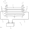
- FIG. 1 An embodiment of a heat exchanger assembly 10 is schematically illustrated in Fig. 1 . It is composed of a heat exchanger 12, a first electrical connector 14, a second electrical connector 16, and an electrical power source 18.
- the heat exchanger 14 is a plate heat exchanger having four parallel plates 20. The plates are rectangular and of stainless steel. This means that each plate 20 has four side sections 28 and four corner sections 3 as indicated in Fig. 1 .
- the plates 20 are joined at the edges (not shown) and forms three channels in which a first fluid 22 and a second fluid 24 flow as indicated by the dashed lines in Fig. 1 .
- the first fluid 22 is sea water and the second fluid 24 is fresh water.
- the flows of the first fluid 22 and the second fluid 24 are generated or provided by pumps (not shown).
- the flow directions of the first fluid 22 and the second fluid 24 are indicated by arrows in Fig. 1 , which shows concurrent flows.
- the flows can be countercurrent, which is achieved by reversing the flow of either the first fluid 22 or the second fluid 24.
- the two central plates 20 form two partitions 26 between which the first fluid 22 flows, thus separating the first fluid 22 from the second fluid 24. Heat can be transferred between the first fluid 22 and the second fluid 24 through the two partitions 26.
- the first fluid 22 has a higher temperature than the second fluid 24 and heat is transferred from the former to the latter.
- the first electrical connector 14 and the second electrical connector 16 are electrical wires that are attached to the inner plates 20 by clamps (not shown).
- the first electrical connector 14 is connected to the lower inner plates 20 and the second electrical connector is connected to the other upper inner plate 20, as is shown in Fig. 1 .
- This means that the first electrical connector 14 and a second electrical connector 16 are structurally connected to different inner plates 20, and also operationally connected to the separating partitions 26. They are also attached at diagonally opposite corner sections 30 of the inner plates 20, as is shown in Fig. 1 .
- first electrical connector 14 and the second electrical connector 16 are spaced apart at the heat exchanger 12, that they are structurally connected to the heat exchanger 12 on opposite sides of the heat exchanger 12, and that they are structurally connected at different corners that are located diagonally with respect to one another.
- first electrical connector 14 is connected to both inner plates 20 and the second connector 16 is also connected only to both inner plates 20.
- the first electrical connector 14 and the second electrical connector 16 are connected to the output terminals of the electrical power source 18. This way the electrical power source 18 can supply an electric current and an electric potential to the separating partitions 26 via the first electrical connector 14 and the second electrical connector 16.
- the second electrical connector 16 is electrically grounded to earth.
- the electrical power source 18 supplies an alternating electric current in the form of a square wave to the first electrical connector 14 and the second electrical connector 16, and in extension to the one or more separating partitions 26.
- the alternating current has an electric peak current between 0.3 mA and 0.7 mA, a frequency below 1 Hz, and a duty cycle of about 50 %.
- the alternating current is supplied at a peak voltage in the range 70 to 90 V.
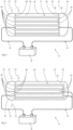
- the heat exchanger 12 is a shell and tube heat exchanger. It has a tube bundle of straight tubes 44 forming the one or more partitions 26 and a shell 46 that encloses the tube bundle.
- Each of the straight tubes 44 are supported at one end by a first tube plate 48 constituting a first tube support and at the other end by a second tube plate 50 constituting a second tube support.
- Each of the straight tubes 44 has an inlet at the first tube plate 48 and an outlet at the second tube plate 50.
- the straight tubes 44, the first tube plate 48 and the second tube plate 50 are of metal and are welded together. This way the components in question are electrically connected to one another and are on the same electric potential.
- the first electrical connector 14 and the second electrical connector 16 are composed of the first tube plate 48 and the second tube plate 50, respectively, and of electric cables connecting the tube plates 48 and 50 to the electrical power source 18. This way, the electrical power source 18 is configured to supply an electric current to the tubes 44, and in extension to the separating partitions 26.
- the first tube plate 48 and the second tube plate 50 connect to the shell 46 and separates the first fluid 22 from the second fluid 24.
- the tube plates 48 and 50 are electrically insulated from the shell 46 by way of a rubber gasket (not shown).
- the first tube plate 48 and the shell 46 forms a first enclosed space 52 that can contain the first fluid 22.
- the heat exchanger 12 has an inlet in the shell 46 through which the first fluid enters the first enclosed space 52.
- the second tube plate 50 and the shell 46 form a second enclosed space 54 that can contain the first fluid 22.
- the heat exchanger 12 has an outlet in the shell 46 through which the first fluid 12 can leave the second enclosed space 54.
- the inlets of the tubes 44 open to the first enclosed space 52 and the outlets of the tubes 44 open to the second enclosed space 54.
- the first tube plate 48, the second tube plate 50, and the shell 46 form a third enclosed space 56 that can contain the second fluid 24.
- the heat exchanger 12 has an inlet and outlet in the shell 46 through which the second fluid 24 can enter and leave the third enclosed space 56.
- Each tube 44 extends from the first enclosed space 52 to the second enclosed space 54 via the third enclosed space 56, thus constituting a first channel through which the first fluid 22 can flow from the first enclosed space 52 to the second enclosed space 54 and pass the second fluid 24 without mixing, thus allowing a heat transfer between the fluids 22 and 24.
- the inlets and outlets to the third enclosed space 56 are positioned such that the second fluid 24 passes the tubes 44. This way, the third enclosed space 56 constitutes a second channel through which the second fluid 24 can flow.
- FIG. 3 Another embodiment of a heat exchanger assembly 10 is schematically illustrated in Fig. 3 .
- the heat exchanger 12 is a shell and tube heat exchanger. It has a tube bundle of tubes 44 that are bent in a U-shape as shown in Fig. 2 .
- the tubes 44 form the one or more partitions 26.
- the embodiment shown in Fig. 3 differs from the embodiment shown in Fig. 2 in that it has no second tube plate 50. Instead, the tubes 44 are supported only by the first tube plate 48.
- the second enclosed space 54 is formed by the first tube plate 48 and the shell 46
- the third enclosed space 56 is formed by the first tube plate 48 and the shell 46, as is shown in Fig. 3 .
- the first enclosed space 52 and the second enclosed space 54 are separated by an extension of the first tube plate 48.
- Each tube 44 extends from the first enclosed space 52 into the third enclosed space 56, bends and returns to the second enclosed space 54 that is juxtaposed to the first enclosed space 52.
- the first electrical connector 14 is composed of the first tube plate 48 and of an electric cable connecting the first tube plate 48 to the electrical power source 18.
- the second electrical connector 16 is composed of electric cables connecting the electrical power source 18 to each of the tubes 44 on the other end of the tube bundle.
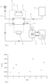
- FIG. 2 A test setup used in a proof-of-concept is illustrated in Fig. 2 .
- the setup included a heat exchanger assembly 10 as described in relation to Fig.1 .
- the electric conductivity of the stainless steel plates 20 of the heat exchanger 12 is high. Therefore, a 51 kOhm resistor (not shown) was placed in series with the heat exchanger 12 to limit the current.
- the test setup has a first tank 32 containing water and a heater 36 arranged to heat the water in the first tank 32.
- the setup further has a jacketed tank 38 containing brackish sea water that constitutes a first fluid 22.
- the jacketed tank 38 is coupled to the first tank 32 so that heat can be received therefrom.
- the test setup also has a second tank 34 containing colder tap water constituting a second fluid 24.
- the test setup further has pressure gauge 40.
- the different components are connected as indicated in Fig. 2 .
- the setup has a number of valves and pumps (not shown) that generates and controls the flows indicated by arrows in Fig. 2 .
- the setup is coupled to a drain 42 such that the tap water in the second tank 34 can empty from the setup after passing the heat exchanger 12.
- the setup also has a number of thermometers (not shown) for measuring the temperature of the first fluid 22 and the second fluid 24 at the respective inlet of the heat exchanger 12.
- the pressure drop ( ⁇ P) of the first fluid 22 was used to characterize the performance of the heat exchanger 12.
- the input temperature (Th,in) of the first fluid 22 was held approximately constant at 40 degrees C
- the input temperature (Tc,in) of the second fluid 24 was held approximately constant at 10 degrees C.
- the electrical power source 18 was operated at a peak current of about 0.54 mA, a peak voltage of about 80 V, and a frequency of 5 Hz.
- the heat exchanger 12 was dismantled and biofilm samples were taken from the inner surfaces of the separating partitions 26 of the heat exchanger 12 facing the first fluid 22 (sea water). Sterile cotton swabs were used, and the same swabbing pattern was repeated. Approximately 2 cm 2 were swabbed each time.
- the electrification of the heat exchanger 12 clearly results in a drop in the count of bacteria, both in total number and in the number of viable bacteria.
- the total number of bacteria is reduced to about 9 %.
- the effect is even greater for viable bacteria, for which the number of bacteria is reduced to less than 3 %. It can be concluded that the electrification greatly reduces the bacterial growth on the partitions of the heat exchanger facing the first fluid 22 (sea water).
- Fig. 3 is a graph showing the pressure drop ( ⁇ P) of the first fluid 22 over the heat exchanger 12 as a function of time. Crosses indicate the results for the electrified setup run, and circles indicate the results for the non-electrified setup run. It can be seen in the graph of Fig. 3 that the pressure drop ( ⁇ P) increases with time for the non-electrified test run, while it is more or less constant for the electrified test run. After 14 days, the pressure difference is about 25% higher without electric current. It is contemplated that this change is caused by the greater microbiological growth in the non-electrified test run than in the electrified test run, and that the growth restricts the flow of the first fluid 22 through the heat exchanger 12.
Landscapes
- Engineering & Computer Science (AREA)
- Physics & Mathematics (AREA)
- General Engineering & Computer Science (AREA)
- Mechanical Engineering (AREA)
- Thermal Sciences (AREA)
- Life Sciences & Earth Sciences (AREA)
- Health & Medical Sciences (AREA)
- Epidemiology (AREA)
- Animal Behavior & Ethology (AREA)
- General Health & Medical Sciences (AREA)
- Public Health (AREA)
- Veterinary Medicine (AREA)
- Polymers & Plastics (AREA)
- Food Science & Technology (AREA)
- Chemical & Material Sciences (AREA)
- Zoology (AREA)
- Wood Science & Technology (AREA)
- Heat-Exchange Devices With Radiators And Conduit Assemblies (AREA)
- Food Preservation Except Freezing, Refrigeration, And Drying (AREA)
Claims (10)
- Ensemble d'échangeur de chaleur (10) comprenant :- un échangeur de chaleur (12) comprenant une pluralité de séparations (26) configurées pour séparer un premier fluide (22) et un deuxième fluide (24) et à travers lesquelles de la chaleur peut être transférée entre le premier fluide (22) et le deuxième fluide (24), dans lequel les séparations (26) sont connectées électriquement l'une à l'autre et partagent le même potentiel électrique,- un premier connecteur électrique (14) et un deuxième connecteur électrique (16) qui sont connectés de façon opérationnelle à la pluralité de séparations (26) de l'échangeur de chaleur (12), et- une source d'alimentation électrique (18) connectée de façon opérationnelle au premier connecteur électrique (14) et au deuxième connecteur électrique (16) et configurée pour fournir un courant électrique à la pluralité de séparations (26) de l'échangeur de chaleur (12) via le premier connecteur électrique (14) et le deuxième connecteur électrique (16) pour réduire la croissance de micro-organismes dans l'échangeur de chaleur.
- Ensemble d'échangeur de chaleur (10) selon la revendication 1, dans lequel l'échangeur de chaleur (12) est configuré pour traiter un produit alimentaire liquide.
- Ensemble d'échangeur de chaleur (10) selon la revendication 1 ou 2, dans lequel les séparations (26) sont structurellement reliées les unes aux autres.
- Ensemble d'échangeur de chaleur (10) selon l'une quelconque des revendications 1 à 3, dans lequel la pluralité de séparations forme une pluralité de premiers canaux à travers lesquels le premier fluide peut s'écouler.
- Ensemble d'échangeur de chaleur (10) selon la revendication 4, dans lequel l'échangeur de chaleur (12) est un échangeur de chaleur à calandre comprenant un faisceau tubulaire avec des tubes (44) constituant les séparations formant la pluralité de premiers canaux.
- Ensemble d'échangeur de chaleur (10) selon la revendication 4, dans lequel la pluralité de séparations (26) forme une pluralité de deuxièmes canaux à travers lesquels le deuxième fluide peut s'écouler, dans lequel l'échangeur de chaleur (12) est un échangeur de chaleur à plaques (12) comprenant une pluralité de plaques (20) formant la pluralité de séparations (26), et dans lequel la pluralité de plaques (20) forme la pluralité de premiers canaux, et la pluralité de deuxièmes canaux.
- Ensemble d'échangeur de chaleur (10) selon la revendication 6, dans lequel les conditions de croissance microbienne est meilleure dans le premier fluide (22) que dans le deuxième fluide (24), et le premier connecteur électrique (14) peut être structurellement connecté à une paire de plaques adjacentes (20) de la pluralité de plaques (20), dans lequel la paire de plaques adjacentes (20) entoure le premier fluide (22).
- Ensemble d'échangeur de chaleur (10) selon la revendication 6 ou 7, dans lequel le premier connecteur électrique (14) et le deuxième connecteur électrique (16) sont structurellement connectés à l'échangeur de chaleur (12) sur des côtés opposés de l'échangeur de chaleur (12).
- Procédé de réduction de la croissance microbiologique dans un échangeur de chaleur (12) d'un ensemble d'échangeur de chaleur (10) selon l'une quelconque des revendications 1 à 8, dans lequel le procédé comprend : la fourniture d'un écoulement du premier fluide (22) et d'un écoulement du deuxième fluide (24) dans l'échangeur de chaleur (12), et l'alimentation en courant électrique de la pluralité de séparations (26) de l'échangeur de chaleur (12) à l'aide de la source d'alimentation électrique (18).
- Pasteurisateur pour le traitement thermique d'un produit alimentaire liquide, dans lequel le pasteurisateur comprend un ensemble d'échangeur de chaleur (10) selon l'une quelconque des revendications 1 à 8 pour chauffer ou refroidir le produit alimentaire liquide.
Priority Applications (1)
| Application Number | Priority Date | Filing Date | Title |
|---|---|---|---|
| EP24220180.4A EP4501365A3 (fr) | 2019-10-07 | 2020-10-06 | Prévention de la croissance microbiologique dans des échangeurs de chaleur |
Applications Claiming Priority (3)
| Application Number | Priority Date | Filing Date | Title |
|---|---|---|---|
| EP19201662.4A EP3805689A1 (fr) | 2019-10-07 | 2019-10-07 | Prévention de la croissance microbiologique dans des échangeurs de chaleur |
| SE2050606A SE544965C2 (en) | 2020-05-26 | 2020-05-26 | A heat exchanger assembly, a pasteurizer, and a method for reducing microbiological growth |
| PCT/EP2020/077902 WO2021069395A1 (fr) | 2019-10-07 | 2020-10-06 | Prévention de la croissance microbiologique dans des échangeurs de chaleur |
Related Child Applications (1)
| Application Number | Title | Priority Date | Filing Date |
|---|---|---|---|
| EP24220180.4A Division EP4501365A3 (fr) | 2019-10-07 | 2020-10-06 | Prévention de la croissance microbiologique dans des échangeurs de chaleur |
Publications (3)
| Publication Number | Publication Date |
|---|---|
| EP4042087A1 EP4042087A1 (fr) | 2022-08-17 |
| EP4042087C0 EP4042087C0 (fr) | 2025-01-15 |
| EP4042087B1 true EP4042087B1 (fr) | 2025-01-15 |
Family
ID=72717885
Family Applications (2)
| Application Number | Title | Priority Date | Filing Date |
|---|---|---|---|
| EP20785751.7A Active EP4042087B1 (fr) | 2019-10-07 | 2020-10-06 | Prévention de la croissance microbiologique dans des échangeurs de chaleur |
| EP24220180.4A Pending EP4501365A3 (fr) | 2019-10-07 | 2020-10-06 | Prévention de la croissance microbiologique dans des échangeurs de chaleur |
Family Applications After (1)
| Application Number | Title | Priority Date | Filing Date |
|---|---|---|---|
| EP24220180.4A Pending EP4501365A3 (fr) | 2019-10-07 | 2020-10-06 | Prévention de la croissance microbiologique dans des échangeurs de chaleur |
Country Status (10)
| Country | Link |
|---|---|
| US (1) | US12203712B2 (fr) |
| EP (2) | EP4042087B1 (fr) |
| JP (2) | JP2022552446A (fr) |
| CN (1) | CN114502906A (fr) |
| AU (1) | AU2020362245B2 (fr) |
| CA (1) | CA3153411A1 (fr) |
| ES (1) | ES3009835T3 (fr) |
| HU (1) | HUE071242T2 (fr) |
| PL (1) | PL4042087T3 (fr) |
| WO (1) | WO2021069395A1 (fr) |
Families Citing this family (3)
| Publication number | Priority date | Publication date | Assignee | Title |
|---|---|---|---|---|
| CN116518766A (zh) * | 2023-04-27 | 2023-08-01 | 浙江大学 | 一种抑制微生物污垢生长的换热器及方法 |
| EP4516889A1 (fr) * | 2023-08-29 | 2025-03-05 | EPFF Electrical Pipe For Fluid transport AB | Prévention de la croissance microbiologique dans des systèmes de traitement |
| EP4517098A1 (fr) * | 2023-08-29 | 2025-03-05 | EPFF Electrical Pipe For Fluid transport AB | Prévention de la croissance microbiologique dans un équipement de traitement |
Family Cites Families (27)
| Publication number | Priority date | Publication date | Assignee | Title |
|---|---|---|---|---|
| GB1323417A (en) * | 1969-08-28 | 1973-07-18 | Courtaulds Ltd | Protecting composite structures from corrosion |
| US4056142A (en) * | 1972-09-09 | 1977-11-01 | Gea Luftkuhlergesellschaft Happel Gmbh & Co. Kg | Heat exchange arrangement |
| FR2319102B1 (fr) | 1975-07-21 | 1986-05-16 | Sgn Soc Gen Tech Nouvelle | Dispositif permettant d'eviter les depots et incrustations sur les parois d'echange |
| US4586562A (en) * | 1983-08-10 | 1986-05-06 | Eltech Systems Corporation | Plate and frame heat exchanger assembly with anodic protection |
| SE8404682D0 (sv) * | 1984-09-19 | 1984-09-19 | Alfa Laval Thermal Ab | Korrosionsskydd for vermevexlare |
| CA2115719C (fr) * | 1994-02-15 | 2000-05-09 | Gordon M. Cameron | Systeme de protection cathodique par anode scrificielle et methode connexe |
| JP4028169B2 (ja) | 2000-11-29 | 2007-12-26 | 株式会社東芝 | 海水に接する構造物および熱交換器の防汚装置 |
| DE10128774A1 (de) * | 2001-06-13 | 2002-12-19 | Outokumpu Oy | Plattenwärmeaustauscher mit anodischem Korrosionsschutz |
| GB2400808B (en) * | 2003-04-23 | 2006-07-12 | Emt Res Asa | Method for flow improvement and reduction of fouling in process equipment |
| DE10324228B4 (de) * | 2003-05-28 | 2006-02-16 | Rittal Gmbh & Co. Kg | Kühlvorrichtung für eine Offshore-Windenergieanlage |
| JP2005147479A (ja) | 2003-11-13 | 2005-06-09 | Pentel Corp | 熱交換器及びその電気化学的制御方法 |
| JP4444001B2 (ja) | 2004-05-28 | 2010-03-31 | 株式会社日阪製作所 | 熱交換装置 |
| JP4552805B2 (ja) * | 2005-08-19 | 2010-09-29 | 株式会社デンソー | 積層型熱交換器及びその製造方法 |
| US7398643B2 (en) * | 2006-05-16 | 2008-07-15 | Dana Canada Corporation | Combined EGR cooler and plasma reactor |
| WO2009051735A2 (fr) * | 2007-10-18 | 2009-04-23 | Roberts, Wayne | Echangeur de chaleur à haute efficacité résistant à la corrosion et ses procédés d'utilisation |
| DE102010004418A1 (de) | 2010-01-13 | 2011-07-14 | GEA TDS GmbH, 31157 | UHT-Anlage zur Wärmebehandlung von temperatursensiblen Lebensmittelprodukten und Verfahren zur Wärmebehandlung von temperatursensiblen Lebensmittelprodukten in einer UHT-Anlage |
| GB201005565D0 (en) | 2010-04-01 | 2010-05-19 | Ceresto Oy | Heat exchanger |
| US8834947B2 (en) | 2010-04-27 | 2014-09-16 | Conopco, Inc. | In-line heating process |
| SE535236C2 (sv) | 2010-10-22 | 2012-06-05 | Alfa Laval Corp Ab | Värmeväxlarplatta och plattvärmeväxlare |
| BR112015008522B1 (pt) * | 2012-10-16 | 2021-01-19 | The Abell Foundation, Inc. | placa de troca de calor e trocador de calor |
| FR3008485B1 (fr) * | 2013-07-12 | 2015-08-21 | Valeo Systemes Thermiques | Echangeur de chaleur |
| KR101789541B1 (ko) | 2015-01-19 | 2017-10-26 | 두산중공업 주식회사 | 열교환기 및 이를 포함한 발전 시스템 |
| US20160265856A1 (en) * | 2015-03-09 | 2016-09-15 | Micro Climate Control Limited | Heat exchangers |
| JP6470093B2 (ja) | 2015-04-15 | 2019-02-13 | 株式会社フロンティアエンジニアリング | 飲食物の製造装置 |
| US10989481B2 (en) * | 2016-05-20 | 2021-04-27 | Modine Manufacturing Company | Heat exchanger and heat exchange system |
| EP3315841B1 (fr) * | 2016-11-01 | 2019-03-27 | EPFF Electrical Pipe For Fluid transport AB | Réduction de la croissance microbiologique dans des tuyaux |
| EP3332653A1 (fr) | 2016-12-09 | 2018-06-13 | Tetra Laval Holdings & Finance S.A. | Échangeur thermique tubulaire |
-
2020
- 2020-10-06 ES ES20785751T patent/ES3009835T3/es active Active
- 2020-10-06 EP EP20785751.7A patent/EP4042087B1/fr active Active
- 2020-10-06 US US17/766,579 patent/US12203712B2/en active Active
- 2020-10-06 CA CA3153411A patent/CA3153411A1/fr active Pending
- 2020-10-06 CN CN202080071013.1A patent/CN114502906A/zh active Pending
- 2020-10-06 AU AU2020362245A patent/AU2020362245B2/en active Active
- 2020-10-06 JP JP2022546723A patent/JP2022552446A/ja active Pending
- 2020-10-06 WO PCT/EP2020/077902 patent/WO2021069395A1/fr not_active Ceased
- 2020-10-06 HU HUE20785751A patent/HUE071242T2/hu unknown
- 2020-10-06 EP EP24220180.4A patent/EP4501365A3/fr active Pending
- 2020-10-06 PL PL20785751.7T patent/PL4042087T3/pl unknown
-
2025
- 2025-02-05 JP JP2025017646A patent/JP2025074083A/ja active Pending
Also Published As
| Publication number | Publication date |
|---|---|
| ES3009835T3 (en) | 2025-04-01 |
| EP4042087C0 (fr) | 2025-01-15 |
| HUE071242T2 (hu) | 2025-08-28 |
| US20230417497A1 (en) | 2023-12-28 |
| PL4042087T3 (pl) | 2025-03-31 |
| JP2022552446A (ja) | 2022-12-15 |
| JP2025074083A (ja) | 2025-05-13 |
| US12203712B2 (en) | 2025-01-21 |
| AU2020362245B2 (en) | 2025-09-18 |
| EP4042087A1 (fr) | 2022-08-17 |
| CA3153411A1 (fr) | 2021-04-15 |
| WO2021069395A1 (fr) | 2021-04-15 |
| EP4501365A3 (fr) | 2025-04-23 |
| US20250137740A1 (en) | 2025-05-01 |
| CN114502906A (zh) | 2022-05-13 |
| AU2020362245A1 (en) | 2022-05-19 |
| EP4501365A2 (fr) | 2025-02-05 |
Similar Documents
| Publication | Publication Date | Title |
|---|---|---|
| EP4042087B1 (fr) | Prévention de la croissance microbiologique dans des échangeurs de chaleur | |
| Cappato et al. | Ohmic heating in dairy processing: Relevant aspects for safety and quality | |
| Kozempel et al. | Inactivation of microorganisms with microwaves at reduced temperaturas | |
| US4417132A (en) | Apparatus for heating electrically conductive flowable media | |
| Wu et al. | Development of an innovative induction heating technique for the treatment of liquid food: Principle, experimental validation and application | |
| US4194953A (en) | Process for producing chlorate and chlorate cell construction | |
| EP0032464A1 (fr) | Appareil pour chauffer des milieux liquides électriquement conducteurs | |
| US12618622B2 (en) | Prevention of microbiological growth in heat exchangers | |
| SE544965C2 (en) | A heat exchanger assembly, a pasteurizer, and a method for reducing microbiological growth | |
| EP3805689A1 (fr) | Prévention de la croissance microbiologique dans des échangeurs de chaleur | |
| JP4995164B2 (ja) | 冷却可能な電極体およびそれを備えた連続式通電加熱装置 | |
| US2324837A (en) | Electric heater | |
| CN105466249B (zh) | 一种模组式管板换热器及其换热方法 | |
| CN217383893U (zh) | 原管换热注射用水降温设备 | |
| CN109618439B (zh) | 星形-星形式三相感应热反应器 | |
| JP2015021708A (ja) | 多管式熱交換器 | |
| CN105466251B (zh) | 一种模组式管板换热器及其换热方法 | |
| JPH0418982A (ja) | 被処理水の電気化学的処理方法 | |
| US12590732B2 (en) | Heating system and methods | |
| RU2625668C1 (ru) | Электробаромембранный аппарат плоскокамерного типа | |
| CN217058447U (zh) | 一种便携式牛奶冷却器 | |
| JP2005069509A (ja) | 熱交換装置 | |
| WO2011015987A1 (fr) | Générateur dozone | |
| CN1759206A (zh) | 用于对卤化物化合物执行电解过程的设备 | |
| US20120061251A1 (en) | Mixed Oxidant Electrolytic Cell |
Legal Events
| Date | Code | Title | Description |
|---|---|---|---|
| STAA | Information on the status of an ep patent application or granted ep patent |
Free format text: STATUS: UNKNOWN |
|
| STAA | Information on the status of an ep patent application or granted ep patent |
Free format text: STATUS: THE INTERNATIONAL PUBLICATION HAS BEEN MADE |
|
| PUAI | Public reference made under article 153(3) epc to a published international application that has entered the european phase |
Free format text: ORIGINAL CODE: 0009012 |
|
| STAA | Information on the status of an ep patent application or granted ep patent |
Free format text: STATUS: REQUEST FOR EXAMINATION WAS MADE |
|
| 17P | Request for examination filed |
Effective date: 20220502 |
|
| AK | Designated contracting states |
Kind code of ref document: A1 Designated state(s): AL AT BE BG CH CY CZ DE DK EE ES FI FR GB GR HR HU IE IS IT LI LT LU LV MC MK MT NL NO PL PT RO RS SE SI SK SM TR |
|
| DAV | Request for validation of the european patent (deleted) | ||
| DAX | Request for extension of the european patent (deleted) | ||
| RAP1 | Party data changed (applicant data changed or rights of an application transferred) |
Owner name: ALFA LAVAL CORPORATE AB |
|
| RAP3 | Party data changed (applicant data changed or rights of an application transferred) |
Owner name: ALFA LAVAL CORPORATE AB |
|
| P01 | Opt-out of the competence of the unified patent court (upc) registered |
Effective date: 20240228 |
|
| GRAP | Despatch of communication of intention to grant a patent |
Free format text: ORIGINAL CODE: EPIDOSNIGR1 |
|
| STAA | Information on the status of an ep patent application or granted ep patent |
Free format text: STATUS: GRANT OF PATENT IS INTENDED |
|
| INTG | Intention to grant announced |
Effective date: 20241008 |
|
| GRAS | Grant fee paid |
Free format text: ORIGINAL CODE: EPIDOSNIGR3 |
|
| GRAA | (expected) grant |
Free format text: ORIGINAL CODE: 0009210 |
|
| STAA | Information on the status of an ep patent application or granted ep patent |
Free format text: STATUS: THE PATENT HAS BEEN GRANTED |
|
| AK | Designated contracting states |
Kind code of ref document: B1 Designated state(s): AL AT BE BG CH CY CZ DE DK EE ES FI FR GB GR HR HU IE IS IT LI LT LU LV MC MK MT NL NO PL PT RO RS SE SI SK SM TR |
|
| REG | Reference to a national code |
Ref country code: CH Ref legal event code: EP Ref country code: GB Ref legal event code: FG4D |
|
| REG | Reference to a national code |
Ref country code: DE Ref legal event code: R096 Ref document number: 602020044868 Country of ref document: DE |
|
| REG | Reference to a national code |
Ref country code: IE Ref legal event code: FG4D |
|
| U01 | Request for unitary effect filed |
Effective date: 20250205 |
|
| U07 | Unitary effect registered |
Designated state(s): AT BE BG DE DK EE FI FR IT LT LU LV MT NL PT RO SE SI Effective date: 20250211 |
|
| P04 | Withdrawal of opt-out of the competence of the unified patent court (upc) registered |
Free format text: CASE NUMBER: APP_6418/2025 Effective date: 20250207 |
|
| REG | Reference to a national code |
Ref country code: GR Ref legal event code: EP Ref document number: 20250400185 Country of ref document: GR Effective date: 20250314 |
|
| REG | Reference to a national code |
Ref country code: ES Ref legal event code: FG2A Ref document number: 3009835 Country of ref document: ES Kind code of ref document: T3 Effective date: 20250401 |
|
| PG25 | Lapsed in a contracting state [announced via postgrant information from national office to epo] |
Ref country code: RS Free format text: LAPSE BECAUSE OF FAILURE TO SUBMIT A TRANSLATION OF THE DESCRIPTION OR TO PAY THE FEE WITHIN THE PRESCRIBED TIME-LIMIT Effective date: 20250415 |
|
| PG25 | Lapsed in a contracting state [announced via postgrant information from national office to epo] |
Ref country code: IS Free format text: LAPSE BECAUSE OF FAILURE TO SUBMIT A TRANSLATION OF THE DESCRIPTION OR TO PAY THE FEE WITHIN THE PRESCRIBED TIME-LIMIT Effective date: 20250515 |
|
| PG25 | Lapsed in a contracting state [announced via postgrant information from national office to epo] |
Ref country code: HR Free format text: LAPSE BECAUSE OF FAILURE TO SUBMIT A TRANSLATION OF THE DESCRIPTION OR TO PAY THE FEE WITHIN THE PRESCRIBED TIME-LIMIT Effective date: 20250115 |
|
| REG | Reference to a national code |
Ref country code: HU Ref legal event code: AG4A Ref document number: E071242 Country of ref document: HU |
|
| PG25 | Lapsed in a contracting state [announced via postgrant information from national office to epo] |
Ref country code: SM Free format text: LAPSE BECAUSE OF FAILURE TO SUBMIT A TRANSLATION OF THE DESCRIPTION OR TO PAY THE FEE WITHIN THE PRESCRIBED TIME-LIMIT Effective date: 20250115 |
|
| PGFP | Annual fee paid to national office [announced via postgrant information from national office to epo] |
Ref country code: GR Payment date: 20250911 Year of fee payment: 6 |
|
| PGFP | Annual fee paid to national office [announced via postgrant information from national office to epo] |
Ref country code: PL Payment date: 20250912 Year of fee payment: 6 |
|
| U20 | Renewal fee for the european patent with unitary effect paid |
Year of fee payment: 6 Effective date: 20250909 |
|
| PGFP | Annual fee paid to national office [announced via postgrant information from national office to epo] |
Ref country code: GB Payment date: 20250828 Year of fee payment: 6 |
|
| PGFP | Annual fee paid to national office [announced via postgrant information from national office to epo] |
Ref country code: IE Payment date: 20250909 Year of fee payment: 6 Ref country code: CZ Payment date: 20250923 Year of fee payment: 6 |
|
| PG25 | Lapsed in a contracting state [announced via postgrant information from national office to epo] |
Ref country code: SK Free format text: LAPSE BECAUSE OF FAILURE TO SUBMIT A TRANSLATION OF THE DESCRIPTION OR TO PAY THE FEE WITHIN THE PRESCRIBED TIME-LIMIT Effective date: 20250115 |
|
| REG | Reference to a national code |
Ref country code: CH Ref legal event code: U11 Free format text: ST27 STATUS EVENT CODE: U-0-0-U10-U11 (AS PROVIDED BY THE NATIONAL OFFICE) Effective date: 20251101 |
|
| PGFP | Annual fee paid to national office [announced via postgrant information from national office to epo] |
Ref country code: HU Payment date: 20250929 Year of fee payment: 6 |
|
| PLBE | No opposition filed within time limit |
Free format text: ORIGINAL CODE: 0009261 |
|
| STAA | Information on the status of an ep patent application or granted ep patent |
Free format text: STATUS: NO OPPOSITION FILED WITHIN TIME LIMIT |
|
| 26N | No opposition filed |
Effective date: 20251016 |
|
| PGFP | Annual fee paid to national office [announced via postgrant information from national office to epo] |
Ref country code: NO Payment date: 20251009 Year of fee payment: 6 |
|
| PGFP | Annual fee paid to national office [announced via postgrant information from national office to epo] |
Ref country code: TR Payment date: 20251002 Year of fee payment: 6 |
|
| PGFP | Annual fee paid to national office [announced via postgrant information from national office to epo] |
Ref country code: CH Payment date: 20251101 Year of fee payment: 6 |
|
| PGFP | Annual fee paid to national office [announced via postgrant information from national office to epo] |
Ref country code: ES Payment date: 20251104 Year of fee payment: 6 |