EP4042537B1 - Procédé de fonctionnement de système de production d'énergie et système de production d'énergie comprenant ledit procédé - Google Patents
Procédé de fonctionnement de système de production d'énergie et système de production d'énergie comprenant ledit procédé Download PDFInfo
- Publication number
- EP4042537B1 EP4042537B1 EP20772278.6A EP20772278A EP4042537B1 EP 4042537 B1 EP4042537 B1 EP 4042537B1 EP 20772278 A EP20772278 A EP 20772278A EP 4042537 B1 EP4042537 B1 EP 4042537B1
- Authority
- EP
- European Patent Office
- Prior art keywords
- sub
- converter
- faulty
- generator
- generators
- Prior art date
- Legal status (The legal status is an assumption and is not a legal conclusion. Google has not performed a legal analysis and makes no representation as to the accuracy of the status listed.)
- Active
Links
Images


Classifications
-
- H—ELECTRICITY
- H02—GENERATION; CONVERSION OR DISTRIBUTION OF ELECTRIC POWER
- H02J—ELECTRIC POWER NETWORKS; CIRCUIT ARRANGEMENTS OR SYSTEMS FOR SUPPLYING OR DISTRIBUTING ELECTRIC POWER; SYSTEMS FOR STORING ELECTRIC ENERGY
- H02J3/00—Circuit arrangements for AC mains or AC distribution networks
- H02J3/38—Arrangements for feeding a single network from two or more generators or sources in parallel; Arrangements for feeding already energised networks from additional generators or sources in parallel
- H02J3/381—Dispersed generators
-
- H—ELECTRICITY
- H02—GENERATION; CONVERSION OR DISTRIBUTION OF ELECTRIC POWER
- H02J—ELECTRIC POWER NETWORKS; CIRCUIT ARRANGEMENTS OR SYSTEMS FOR SUPPLYING OR DISTRIBUTING ELECTRIC POWER; SYSTEMS FOR STORING ELECTRIC ENERGY
- H02J1/00—Circuit arrangements for DC mains or DC distribution networks
- H02J1/10—Parallel operation of DC sources
- H02J1/102—Parallel operation of DC sources being switching converters
-
- H—ELECTRICITY
- H02—GENERATION; CONVERSION OR DISTRIBUTION OF ELECTRIC POWER
- H02J—ELECTRIC POWER NETWORKS; CIRCUIT ARRANGEMENTS OR SYSTEMS FOR SUPPLYING OR DISTRIBUTING ELECTRIC POWER; SYSTEMS FOR STORING ELECTRIC ENERGY
- H02J1/00—Circuit arrangements for DC mains or DC distribution networks
- H02J1/08—Three-wire DC power distribution systems; Systems having more than three wires
- H02J1/082—DC supplies with two or more different DC voltage levels
-
- H—ELECTRICITY
- H02—GENERATION; CONVERSION OR DISTRIBUTION OF ELECTRIC POWER
- H02J—ELECTRIC POWER NETWORKS; CIRCUIT ARRANGEMENTS OR SYSTEMS FOR SUPPLYING OR DISTRIBUTING ELECTRIC POWER; SYSTEMS FOR STORING ELECTRIC ENERGY
- H02J1/00—Circuit arrangements for DC mains or DC distribution networks
- H02J1/08—Three-wire DC power distribution systems; Systems having more than three wires
- H02J1/084—Three-wire DC power distribution systems; Systems having more than three wires for selectively connecting the load or loads to one or several among a plurality of power lines or power sources
- H02J1/086—Three-wire DC power distribution systems; Systems having more than three wires for selectively connecting the load or loads to one or several among a plurality of power lines or power sources for providing alternative feeding paths between load or loads and source or sources when the main path fails
-
- H—ELECTRICITY
- H02—GENERATION; CONVERSION OR DISTRIBUTION OF ELECTRIC POWER
- H02J—ELECTRIC POWER NETWORKS; CIRCUIT ARRANGEMENTS OR SYSTEMS FOR SUPPLYING OR DISTRIBUTING ELECTRIC POWER; SYSTEMS FOR STORING ELECTRIC ENERGY
- H02J7/00—Circuit arrangements for charging or discharging batteries or for supplying loads from batteries
- H02J7/34—Parallel operation in networks using both storage and other DC sources, e.g. providing buffering
- H02J7/35—Parallel operation in networks using both storage and other DC sources, e.g. providing buffering with light sensitive cells
-
- H—ELECTRICITY
- H02—GENERATION; CONVERSION OR DISTRIBUTION OF ELECTRIC POWER
- H02J—ELECTRIC POWER NETWORKS; CIRCUIT ARRANGEMENTS OR SYSTEMS FOR SUPPLYING OR DISTRIBUTING ELECTRIC POWER; SYSTEMS FOR STORING ELECTRIC ENERGY
- H02J2101/00—Supply or distribution of decentralised, dispersed or local electric power generation
- H02J2101/20—Dispersed power generation using renewable energy sources
- H02J2101/22—Solar energy
- H02J2101/24—Photovoltaics
-
- Y—GENERAL TAGGING OF NEW TECHNOLOGICAL DEVELOPMENTS; GENERAL TAGGING OF CROSS-SECTIONAL TECHNOLOGIES SPANNING OVER SEVERAL SECTIONS OF THE IPC; TECHNICAL SUBJECTS COVERED BY FORMER USPC CROSS-REFERENCE ART COLLECTIONS [XRACs] AND DIGESTS
- Y02—TECHNOLOGIES OR APPLICATIONS FOR MITIGATION OR ADAPTATION AGAINST CLIMATE CHANGE
- Y02E—REDUCTION OF GREENHOUSE GAS [GHG] EMISSIONS, RELATED TO ENERGY GENERATION, TRANSMISSION OR DISTRIBUTION
- Y02E10/00—Energy generation through renewable energy sources
- Y02E10/50—Photovoltaic [PV] energy
- Y02E10/56—Power conversion systems, e.g. maximum power point trackers
Definitions
- the invention relates to a method for operating an energy generation system (EEA).
- the invention relates to the operation of an EEA, in which a fault within the EEA is detected and its damaging effect on components of the EEA is avoided, or at least reduced.
- the EEA can in particular be a regenerative EEA with several DC sub-generators, which are connected in parallel to one another and each via a DC/DC converter to a common DC load in order to supply it.
- An error case can occur in particular if one, possibly several, of the DC sub-generators have an error, for example a short-circuit error.
- the invention further relates to an EEA that is designed and set up for such a method.
- the electrolyzer Since the electrolyzer operates as a DC consumer, it is advantageous in order to avoid conversion losses if the island network is also designed as a DC network.
- the EEA within the island network can have several DC sub-generators designed as photovoltaic (PV) sub-generators, each via a DC/DC converter and in parallel with one another with an input of the electrolyzer or another DC load are connected.
- the DC/DC converters can be used to decouple a voltage from the DC sub-generators from a voltage at the input of the electrolyzer.
- the operating point of the electrolyzer in particular its power consumption, can be adjusted via the output voltage of the DC/DC converter.
- a higher-level control unit can regulate the output voltage of the DC/DC converters in such a way that, on the one hand, there is always a balance between the total power generated and consumed in the island network, and on the other hand, the maximum possible power of regeneratively generated power from the PV sub-generators can always be harvested .
- a DC sub-generator usually includes one or more DC sources.
- the DC sources of a DC sub-generator are - depending on the size of the EEA - connected to the DC/DC converter assigned to the DC sub-generator via one or more fuses.
- a resulting current from the fault-free DC sources of the EEA into the faulty DC source is not sufficiently high to at least one of the fuses over which the faulty DC source is connected connected to its assigned DC/DC converter.
- the fault current generated will not be sufficient without further measures to isolate the faulty DC source from the remaining fault-free DC sources by tripping a fuse connected downstream of the faulty DC source.
- the resulting current which represents a fault current, is not safely interrupted and, depending on the current strength and duration of the fault current, can damage or even destroy other components of the EEA, in particular the affected DC/DC converter.
- the font DE 10 2015 007 443 A1 discloses a method and a device for the supplementary feeding of electricity from at least one power source into a final power network with several consumption points.
- the final power network is connected to a higher-level power supply, with the consumption points being protected against the higher-level power supply via at least one overcurrent fuse.
- a control unit records the current flowing in from the higher-level power supply and the current flowing from the power source into the final power network.
- the instantaneous sum value formed from the currents is compared with a predetermined maximum current in order to reduce the current flowing in from the power source when the maximum current is exceeded.
- the method can be used to prevent an overload in the final power network.
- the publication DE 10 2013 111 869 A1 discloses a PV system with an inverter, which is connected to a power supply network via an AC isolator, and at least one PV sub-generator, each of which has at least one PV string and which is connected to a DC connection area of the inverter via DC lines is.
- the PV sub-generator is assigned a DC separation unit close to the generator, a DC short-circuit switch connected downstream in the energy flow direction when feeding in for short-circuiting the at least one PV string and a reverse current protection connected downstream of the DC short-circuit switch in the energy flow direction.
- an AC short-circuit switch is arranged in front of the AC isolating element in the energy flow direction.
- PV photovoltaic
- a PV string is connected to a power converter via first power lines, a DC-DC converter and further power lines.
- the arc detection device includes capacitors that form bypass current paths for the DC-DC converter and a current sensor that is arranged on one of the further power lines between the DC/DC converter and the power converter.
- PV system is known with a large number of PV modules and DC/DC converters assigned to them, which are connected to a central inverter in parallel on the output side.
- the inverter converts an intermediate circuit direct voltage generated by the DC/DC converters into a sinusoidal alternating voltage.
- the PV modules are electrically decoupled by their individual DC/DC converters.
- the publication US 2012/0319489 A1 discloses a multiple PV string photovoltaic (PV) array system in which each PV string is connected in series with a first terminal of a string equalizer module.
- the string equalizer module can equalize a voltage of a maximum power operating point of the PV string before the PV strings are combined to produce a single, composite DC bus voltage on a DC bus.
- PV strings can absorb power from or output power to other PV strings to balance the voltage of the maximum power operating point of each corresponding PV string.
- the invention is based on the object of specifying a method for operating an EEA with several DC sub-generators connected in parallel, with which damage to the EEA is reliably avoided in the event of a fault.
- a faulty DC source of a DC sub-generator should, if possible, be separated from the remaining fault-free DC sources by tripping a fuse.
- the resulting fault current should be controlled in such a way that damage to overcurrent-sensitive components of the EEA is ruled out in any case - even if it is not possible to trip the fuse. It is also an object of the invention to demonstrate an EEA suitable for carrying out the method.
- Each of the DC/DC converters can therefore be connected to only one DC source on the input side.
- a power flow from the DC sources can be cascaded into several stages within the corresponding DC sub-generator.
- Each individual stage can have a separate fuse.
- a so-called main string fuse can protect a generator box that contains many so-called string fuses.
- several fuses of different types can be connected in series between a DC source and the DC/DC converter.
- a tripping threshold of the fuses can increase with increasing distance from the DC source and with decreasing distance to the DC/DC converter.
- Each of the DC sub-generators can be monitored for an error by detecting an electrical parameter of the DC sub-generators, in particular a current and/or a voltage, in succession over time. It is not necessary for each of the DC sources within a DC sub-generator to be monitored separately. In particular, if a plurality of DC sources connected in parallel are connected to a shared DC/DC converter as a DC sub-generator, it is sufficient to combine the DC sources into groups, in other words the corresponding DC sub-generator , to monitor. During monitoring, for example, it can be detected whether a reverse current flows into a faulty DC sub-generator that is affected by a short-circuit fault. The monitoring then does not directly provide the faulty DC source, but still the DC sub-generator that contains the faulty DC source.
- those DC/DC converters that are not assigned to a faulty DC sub-generator are now operated with the aim that their common total current I Rest corresponds to a default value.
- This can be done via coordinated control of those DC/DC converters that do not comply with this assigned to the faulty DC sub-generator.
- the coordinated regulation can be carried out by means of a control unit that acts on all DC/DC converters.
- the control unit In coordinated control, the control unit must take into account the default value to be adjusted.
- the control unit can have the currents of all DC/DC converters involved in the coordinated control in detail. However, this is not absolutely necessary.
- the control unit has, in addition to the default value to be adjusted, the common total current I rest of the DC/DC converters involved in the coordinated control.
- the common total current I Rest can optionally also contain a portion that flows from the DC load in the direction of the DC/DC converter that is assigned to the faulty DC sub-generator. Since fewer values have to be measured and/or communicated during the coordinated control, the coordinated control can be simplified overall and the corresponding control unit can be designed more simply. A fault current corresponding to the total current I Rest therefore does not flow uncontrolled, but rather is controlled in particular in terms of its current strength in such a way that the total current I Rest corresponds to the specified value.
- the default value can be chosen so that damage to an overcurrent-sensitive component of the EEA, in particular the DC/DC converter that is assigned to the faulty DC sub-generator or, which is equivalent, to the faulty DC source, is excluded is.
- the overcurrent-sensitive component can in particular be a freewheeling diode of the corresponding DC/DC converter.
- the total current I Rest can be limited upwards via the default value. By regulating the DC/DC converters in question with the aim of ensuring that the common total current I Rest corresponds to the specified value, the total current I Rest is also limited downwards at the same time.
- the default value can be chosen so that the fuse connected in series to the DC/DC converter and the faulty DC source, or - in the case of several fuses - one or more of the fuses connected in series to the DC/DC converter and reliably trigger the fuses connected to the faulty DC source.
- the fuse that is closest to the faulty DC source will be triggered first, since it is usually relative to the further fuses within the DC sub-generator, on the one hand, has a relatively low triggering threshold, and on the other hand, not only is flowed through by the total current I Rest generated outside the faulty DC sub-generator, but also by a fault current generated within the faulty DC sub-generator.
- the error current generated within the faulty DC sub-generator is generally significantly lower than the total current I Rest generated outside the faulty DC sub-generator. Both currents add up and thus support the desired tripping of the fuse in the event of a fault.
- At least one current (I 2 - I n ) can be reduced by a respective DC/DC converter that is not assigned to the faulty DC sub-generator. Alternatively, however, several or all currents (I 2 - I n ) can also be reduced by the respective DC/DC converters in order to set the total current I Rest to the default value. Conversely, if the total current I Rest falls below or threatens to fall below the specified value, at least one current (I 2 - I n ) can pass through a respective DC/DC converter, and possibly also several or all of the currents through the respective DC/DC converters. DC converters that are not assigned to the faulty DC sub-generator can be increased.
- a current flowing through the DC/DC converter can be detected.
- a faulty one can occur DC sub-generator can be indexed when the current flowing from the DC/DC converter assigned to the DC sub-generator in the direction of the DC load falls below a current threshold value I TH , or in particular when that of the DC sub-generator assigned to the DC sub-generator DC/DC converter current flowing towards the DC load changes its current direction.
- a current flowing from the DC/DC converter in the direction of the DC load is evaluated as a positive current and a current flowing from the direction of the DC load to the DC/DC converter is evaluated as a negative current.
- a negative current flowing via the DC/DC converter in the direction of the DC load also indicates that a faulty DC sub-generator is connected to the input side of the DC/DC converter in question.
- an input current or an output current of the DC/DC converter can be detected.
- a voltage of the DC sub-generator in each case in order to monitor the DC sub-generators for a fault.
- a faulty DC sub-generator is indicated when the voltage detected at the DC sub-generator falls below a voltage threshold value U TH .
- the detection of the voltages can advantageously take place on the input side of the DC/DC converters assigned to the respective DC sub-generators.
- the output voltages of the DC/DC converters can also be detected.
- measuring units can be used that are already available in the DC/DC converters.
- the aim of such a choice of the default value is to trigger the fuse and thus the faulty DC source from the remaining non-faulty DC sources within the faulty DC sub-generator, as well as from the remaining non-faulty DC sources outside the faulty DC Separate the sub-generator.
- a de-energized state is brought about between the DC/DC converters, in which the faulty DC source or the faulty DC sub-generator can be galvanically isolated from the common DC load via an electromechanical switching element.
- Such switching elements are usually present in the EEA in question anyway. However, since the switching operation takes place in a de-energized state, it is not absolutely necessary for the switching elements to have arc-extinguishing means. They can therefore be designed to be significantly more cost-effective.
- an error indicated when monitoring the DC sub-generators, and optionally also a successful or unsuccessful tripping of the fuse can be signaled by the EEA.
- This can be done, for example, by an EEA communication unit.
- an EEA operator can be informed promptly about the error and any necessary repair measures. He can do this in advance Take precautions to repair the faulty DC source or EEA as efficiently as possible.
- a power generation system comprises several DC sub-generators, which are each connected in parallel to one another via a DC/DC converter to a common DC load.
- Each of the DC sub-generators has a DC source which is connected to the DC/DC converter assigned to the respective DC sub-generator via at least one fuse connected in series with the DC source.
- the energy generation system also has a control unit which is designed and set up to carry out the method according to the invention.
- the control unit can be a separately designed control unit of the EEA. Alternatively or cumulatively, however, it is also possible for the control unit to be contained within a control unit of a DC/DC converter or within several control units of the DC/DC converters. In other words, the control unit can therefore also be distributed across the control units of several DC/DC converters of the EEA. This results in the advantages already mentioned in connection with the process.
- the DC sub-generators each have several DC sources which are connected in parallel to one another via at least one fuse to the DC/DC converter assigned to the respective DC sub-generator.
- the DC sources can also be connected via a series connection of several fuses to the DC/DC converter assigned to the respective DC sub-generator.
- a tripping threshold or limit load integral of the fuses may increase the further the fuse in the series connection is from the DC source, or, equivalently, the closer the fuse in the series connection is to the corresponding DC/DC -Transducer is arranged.
- the DC sources of one or more DC sub-generators can include a photovoltaic (PV) string and/or a battery.
- the common DC load can in particular include an electrolyzer.
- the EEA can include a buck converter as a DC/DC converter.
- a DC/DC converter several or possibly all DC/DC converters of the EEA can each include a buck converter and/or each include a DC/DC converter that has a step-down function, i.e. designed and is set up to convert an input voltage into a smaller output voltage.
- the overcurrent-sensitive component of the DC/DC converter assigned to the faulty DC source, or, which is equivalent, of the DC/DC converter assigned to the faulty DC sub-generator can comprise a separate freewheeling diode connected in parallel to a semiconductor switch of the DC/DC converter .
- the overcurrent-sensitive component of the DC/DC converter can also include a semiconductor switch of the DC/DC converter, in particular a body diode of the semiconductor switch.
- MPP Maximum PowerPoint
- a voltage U 1 - U n of the DC source 2.1 - 2.n which is assigned to the respective MPP and is present at an input 10.1 - 10.n of the DC/DC converter 4.1 - 4.n assigned to it, is converted into a common one Output voltage U a converted.
- the electrolyzer 21 is supplied as a common DC load 20 with the output voltage U a . This ensures that the maximum possible regenerative power is always converted by the EEA 1 and supplied to the DC load 20.
- the DC sub-generators 5.1 - 5.n are monitored for a possible error 30, for example a possible short-circuit error.
- the monitoring takes place in Fig. 1 in such a way that measuring devices (in Fig. 1 not shown).
- the measuring devices can be used to measure a voltage U 1 - U n present at the input 10.1 - 10.n of the DC/DC converters 4.1 - 4.n and/or a voltage U 1 - U n via the output 11.1 - 11.n of the DC/DC converters 4.1 - 4.n current I 1 - I n flowing in the direction of the DC load 20 can be detected.
- the error 30 is recognized by the control unit 15 on the basis of the detected currents I 1 - I n and/or voltages U 1 - U n .
- the default value is chosen so that, on the one hand, damage to an overcurrent-sensitive component of the DC/DC converter 4.1, which is connected to the faulty DC sub-generator 5.1, is excluded. Specifically, the default value can be selected so that it is smaller than a limit load integral of the overcurrent-sensitive component of the corresponding DC/DC converter 2.1. On the other hand, however, the default value is chosen as high as possible so that a fuse 9.1 connected downstream of the faulty DC source 2.1 safely trips and thus separates the faulty DC source 2.1 from the remaining fault-free DC sources 2.2 - 2.n.
- Fig. 1 Only one faulty DC sub-generator 5.1 is shown, the method can also be transferred to a case with several faulty DC sub-generators present at the same time. This applies at least as long as a number of error-free DC sub-generators outweighs a number of faulty DC sub-generators.
- a limit load integral of the fuses 9.1 - 9.n within each of the series connections increases as the distance of the fuse 9.1 - 9.n from the DC source 2.1 - 2.n assigned to it increases.
- a DC separation unit 13.1 - 13.n is also arranged between each of the DC sub-generators 5.1 - 5.n and the DC/DC converter 4.1 - 4.n assigned to it, with which the corresponding DC sub-generator 5.1 - 5.n can be galvanically isolated from the DC/DC converter 4.1 - 4.n assigned to it.
- the DC separation units 13.1 - 13.n can advantageously be designed to be free of means for extinguishing an arc and therefore relatively inexpensive.
- error 30 is detected by the control unit 15 by monitoring the DC sub-generators 5.1 - 5.n.
- the remaining DC/DC converters 4.2 - 4.n each of which is assigned to an error-free DC sub-generator 5.2 - 5.n, are operated via the control unit 15 with the aim that the total current I generated by them remains a assumes default value.
- the default value is chosen so (low) that, on the one hand, an overcurrent-sensitive component of the DC/DC converter 4.1 assigned to the faulty DC sub-generator 5.1 is protected and its damage is avoided.
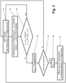
- the Fig. 3 shows a variant of the method according to the invention in the form of a flow chart, as with the EEA 1 according to Fig. 1 or according to EEA 1 Fig. 2 can be carried out.
- the method starts in a first step S1 with MPP operation of all error-free DC sub-generators 5.1 - 5.n. Since at the beginning of the method it is assumed, for example, that there are no faulty DC sources 2.1, and therefore no faulty DC sub-generators 5.1, the number of all fault-free DC sub-generators at the beginning also corresponds to the number of all available DC sub-generators 5.1 - 5.n of EEA 1.
- a second step S2 all DC sub-generators 5.1 - 5.n of EEA 1 that are currently in operation are monitored for an error 30. Monitoring is carried out by sending a voltage U 1 - U n of the DC sub-generators 5.1 - 5.n and/or a voltage via the output 11.1 - 11.n of the DC/DC converters 4.1 - 4.n in the direction of the DC -Last 20 flowing current I 1 - I n is detected and transmitted to the control unit 15.
- the control unit 15 checks whether one of the detected voltages U 1 - U n falls below a voltage threshold value U TH and/or one of the detected currents I 1 - I n falls below a current threshold value I TH .
- the method jumps to a fourth step S4, in which all remaining DC/DC converters 4.1 - 4.n that are in operation, which are not assigned to the faulty DC sub-generator 5.k, via the control unit 15 with the goal operated so that their total current I Rest assumes a default value. This limits the total current I Rest both upwards and downwards.
- a fifth step S5 it is checked whether the total current I Rest was able to trigger a fuse 9.k connected downstream of the faulty DC source 2.k. This can be checked, for example, by detecting current I k and/or voltage U k of the DC/DC converter 4.k assigned to the faulty DC sub-generator 5.k.
- the fuse 9.k has not tripped if a current I k flowing via the output 11.k of the DC/DC converter 4.k in the direction of the DC load still exceeds the current threshold value I TH falls below and/or a voltage U k present at the input 11.k of the DC/DC converter 4.k continues to fall below the voltage threshold value U TH .
- the method assumes that the fuse 9.k connected downstream of the faulty DC source 2.k has tripped and as a result the faulty DC source 2.k has been separated from the common DC load 20 .
- the DC sub-generator which was previously indicated as a faulty DC sub-generator 5.k, shows signs of failure after the fuse 9.k again exclusively error-free DC sources 2.k, can therefore again be referred to as an error-free DC sub-generator and can continue to be operated. Accordingly, when fuse 9.k is triggered, the method jumps back to the first step S1, in which all error-free DC sub-generators are again operated in their MPP.
- the number of DC sub-generators continues to correspond to the total number of sub-generators of EEA 1. However, the DC sub-generator 5.k, which was previously identified as faulty, now has at least one less DC source 2.k.
- step S5 If, however, it is concluded in the fifth step S5 that a fuse 9.k downstream of the faulty DC source 2.k has not tripped, then in a sixth step S6 all remaining DC/DC converters 4.1 - 4.n, which are not assigned to the faulty DC sub-generator 5.k, deactivated, whereby their total current I Rest assumes the value 0A. Thereafter, in a seventh step S7, the faulty DC sub-generator 5.k is electrically isolated from the common DC load 20 and from the remaining fault-free DC sub-generators via the DC isolation unit 13.k assigned to it. The method then jumps to the first step S1, in which all error-free DC sub-generators are again operated in their respective MPP. However, the EEA 1 will now continue to be operated without the DC sub-generator 5.k, which was previously identified as faulty; the number of error-free sub-generators has reduced by 1 in this case.
Landscapes
- Engineering & Computer Science (AREA)
- Power Engineering (AREA)
- Dc-Dc Converters (AREA)
- Direct Current Feeding And Distribution (AREA)
- Protection Of Static Devices (AREA)
Claims (12)
- Procédé pour faire fonctionner un système de production énergétique (EEA ; 1) comportant plusieurs générateurs partiels DC (5.1 - 5.n) reliés à une charge DC commune (20) en parallèle les uns aux autres respectivement par un transducteur DC/DC (4.1 - 4.n), chacun des générateurs partiels DC (5. 1 - 5.n) ayant une source DC (2.1 - 2.n) reliée par au moins un fusible (9.1 - 9.n) monté en série avec la source DC (2.1 - 2.n) au transducteur DC/DC (4.1 - 4.n) associé au générateur partiel DC (5.1 - 5.n) respectif,
comprenant les étapes suivantes :- surveillance de chacun des générateurs partiels DC (5.1 - 5.n) pour détecter un défaut de court-circuit,- durant laquelle, lorsque la surveillance des générateurs partiels DC (5.1 - 5.n) indique un générateur partiel DC (5.1) défectueux,- les transducteurs DC/DC (4.2 - 4.n) qui ne sont pas associés au générateur partiel DC (5.1) défectueux sont exploités avec un courant total commun IRest qui correspond à une valeur par défaut,- la valeur par défaut étant choisie de telle sorte qu'une intégrale de temps formée par le courant total IRest dépasse une intégrale de charge limite du fusible (9.1) oud'un des fusibles (9.1) monté(s) en série entre la source DC (2.1) défectueuse et le transducteur DC/DC (4.1) associé à la source DC (2.1) défectueuse, afin de déclencher ce fusible (9.1). - Procédé pour faire fonctionner un système de production énergétique (EEA ; 1) comportant plusieurs générateurs partiels DC (5.1 - 5.n) reliés à une charge DC commune (20) en parallèle les uns aux autres respectivement par un transducteur DC/DC (4.1 - 4.n), chacun des générateurs partiels DC (5. 1 - 5.n) ayant une source DC (2.1 - 2.n) reliée par au moins un fusible (9.1 - 9.n) monté en série avec la source DC (2.1 - 2.n) au transducteur DC/DC (4.1 - 4.n) associé au générateur partiel DC (5.1 - 5.n) respectif,
comprenant les étapes suivantes :- surveillance de chacun des générateurs partiels DC (5.1 - 5.n) pour détecter un défaut de court-circuit,- durant laquelle, lorsque la surveillance des générateurs partiels DC (5.1 - 5.n) indique un générateur partiel DC (5.1) défectueux,- les transducteurs DC/DC (4.2 - 4.n) qui ne sont pas associés au générateur partiel DC (5.1) défectueux sont exploités avec un courant total commun IRest qui correspond à une valeur par défaut,- la valeur par défaut étant choisie de telle sorte qu'une intégrale de temps formée par le courant total IRest soit inférieure à une intégrale de charge limite d'un composant sensible aux surintensités du transducteur DC/DC (4.1) associé à la source DC (2.1) défectueuse. - Procédé selon l'une des revendications précédentes, dans lequel,- lors de la surveillance des générateurs partiels DC (5.1 - 5.n), un courant (I1 - In) passant par le transducteur DC/DC (4.1 - 4.n) est détecté, et une source DC défectueuse (2.1) est indiquée lorsque le courant (I1) passant par le transducteur DC/DC associé (4. 1) en direction de la charge DC (20) passe en dessous d'une valeur limite de courant ITH, en particulier lorsque le courant (I1) circulant depuis le transducteur DC/DC (4.1) associé en direction de la charge DC (20) change de direction, et/ou- dans lequel, pour la surveillance des générateurs partiels DC (5.1 - 5.n), une tension (U1 - Un) des générateurs partiels DC (5.1 - 5.n) est respectivement détectée, et dans lequel un générateur partiel DC (5.1) défectueux est indiqué lorsque la tension U1 détectée du générateur partiel DC (5.1) est inférieure à une valeur limite de tension UTH.
- Procédé selon la revendication 3, dans lequel un courant d'entrée ou un courant de sortie du transducteur DC/DC (4.1 - 4.n) est détecté en tant que courant (I1 - In) détecté circulant à travers le transducteur DC/DC (4.1 - 4.n).
- Procédé selon l'une des revendications précédentes, dans lequel la valeur par défaut est choisie de telle sorte qu'une intégrale de temps formée par le courant total IRest dépasse une intégrale de charge limite du fusible (9.1) ou d'un des fusibles (9.1) monté(s) en série entre la source DC défectueuse (2.1) et le transducteur DC/DC (4.1) associé à la source DC défectueuse (2.1), afin de déclencher ce fusible (9.1), et dans lequel, si le fusible (9.1) ne se déclenche pas à la valeur par défaut sélectionnée, les transducteurs DC/DC (4.2 - 4.n) qui ne sont pas associés au générateur partiel DC (5.1) défectueux sont désactivés afin de régler le courant total IRest à une valeur de courant de 0A, et, en option, le string partiel DC (5.1) défectueux est séparé de la charge DC commune (20) par un dispositif de séparation DC (13.1).
- Procédé selon l'une des revendications précédentes, dans lequel un défaut (30) indiqué lors de la surveillance des générateurs partiels DC (5.1 - 5.n), éventuellement aussi un déclenchement réussi ou non du fusible (9.1), est signalé par l'EEA (1), en particulier par une unité de communication de l'EEA (1).
- Système de production énergétique (EEA ; 1) avec plusieurs générateurs partiels DC (5.1 - 5.n) reliés à une charge DC (20) commune en parallèle les uns aux autres respectivement par un transducteur DC/DC (4.1 - 4.n), chacun des générateurs partiels DC (5.1 - 5.n) ayant une source DC (2.1 - 2.n) reliée par au moins un fusible (9.1 - 9.n) monté en série avec la source DC (2.1 - 2.n) au transducteur DC/DC (4.1 - 4.n) associé au générateur partiel DC (5.1 - 5.n) respectif, caractérisé en ce que le système de production d'énergie (1) comporte en outre une unité de commande (15) qui est conçue et agencée pour exécuter un procédé selon l'une des revendications précédentes.
- Système de production énergétique (1) selon la revendication 7, dans laquelle les générateurs partiels DC (5.1 - 5.n) présentent chacun plusieurs sources DC (2.1 - 2.n) reliées en parallèle les unes aux autres par au moins un fusible au transducteur DC/DC (4.1 - 4.n) associé au générateur partiel DC (5.1 - 5.n) respectif.
- Système de production énergétique (1) selon la revendication 7 ou 8, dans laquelle les sources DC (2.1 - 2.n) comprennent un string photovoltaïque (PV) (3.1 - 3.n) et/ou une batterie.
- Système de production énergétique (1) selon l'une des revendications 7 à 9, dans laquelle la charge DC commune (20) comprend un électrolyseur (21).
- Système de production énergétique (1) selon l'une des revendications 7 à 10, dans laquelle les transducteurs DC/DC (4.1 - 4.n) comprennent un convertisseur abaisseur et/ou dans laquelle les transducteurs DC/DC (4.1 - 4.n) sont conçus et agencés pour une fonction abaisseur.
- Système de production énergétique (1) selon l'une des revendications 7 à 11, dans laquelle le composant sensible aux surintensités du transducteur DC/DC (4.1) associé à la source DC (2.1) défectueuse comprend une diode de roue libre séparée connectée en parallèle à un commutateur à semi-conducteur (6.1) du transducteur DC/DC (4.1) ou un commutateur à semi-conducteur (6.1) du transducteur DC/DC (4.1), en particulier une diode de corps du commutateur à semi-conducteur (6.1).
Applications Claiming Priority (2)
| Application Number | Priority Date | Filing Date | Title |
|---|---|---|---|
| DE102019127198.3A DE102019127198B4 (de) | 2019-10-09 | 2019-10-09 | Verfahren zum betrieb einer energieerzeugungsanlage und energieerzeugungsanlage mit dem verfahren |
| PCT/EP2020/075742 WO2021069181A1 (fr) | 2019-10-09 | 2020-09-15 | Procédé de fonctionnement de système de production d'énergie et système de production d'énergie comprenant ledit procédé |
Publications (3)
| Publication Number | Publication Date |
|---|---|
| EP4042537A1 EP4042537A1 (fr) | 2022-08-17 |
| EP4042537C0 EP4042537C0 (fr) | 2023-12-20 |
| EP4042537B1 true EP4042537B1 (fr) | 2023-12-20 |
Family
ID=72521624
Family Applications (1)
| Application Number | Title | Priority Date | Filing Date |
|---|---|---|---|
| EP20772278.6A Active EP4042537B1 (fr) | 2019-10-09 | 2020-09-15 | Procédé de fonctionnement de système de production d'énergie et système de production d'énergie comprenant ledit procédé |
Country Status (7)
| Country | Link |
|---|---|
| US (1) | US12549011B2 (fr) |
| EP (1) | EP4042537B1 (fr) |
| JP (1) | JP7618660B2 (fr) |
| CN (1) | CN114503386B (fr) |
| AU (1) | AU2020362873B2 (fr) |
| DE (1) | DE102019127198B4 (fr) |
| WO (1) | WO2021069181A1 (fr) |
Families Citing this family (4)
| Publication number | Priority date | Publication date | Assignee | Title |
|---|---|---|---|---|
| EP4164079A1 (fr) | 2021-10-07 | 2023-04-12 | Siemens Energy Global GmbH & Co. KG | Système de transmission électrique pour consommateurs flexibles |
| JP7705696B2 (ja) * | 2022-05-16 | 2025-07-10 | 株式会社Tmeic | 電力変換装置 |
| DE102022117791A1 (de) * | 2022-07-15 | 2024-01-18 | Sma Solar Technology Ag | Vorrichtung und verfahren zur spannungsangleichung mehrerer zweipole, sowie dc-energieverteilungsanlage |
| CN121546932A (zh) * | 2026-01-16 | 2026-02-17 | 深圳市三和电力科技有限公司 | 三段式电解槽制氢供电系统及其供电控制方法 |
Family Cites Families (21)
| Publication number | Priority date | Publication date | Assignee | Title |
|---|---|---|---|---|
| DE10136147B4 (de) * | 2001-07-25 | 2004-11-04 | Kolm, Hendrik, Dipl.-Ing. | Photovoltaischer Wechselstromerzeuger |
| US10374505B2 (en) * | 2004-12-16 | 2019-08-06 | John Wood | Power coupler |
| US20090266397A1 (en) * | 2008-04-23 | 2009-10-29 | Gm Global Technology Operations, Inc. | Solar battery charging system and optional solar hydrogen production system for vehicle propulsion |
| US8217534B2 (en) * | 2009-05-20 | 2012-07-10 | General Electric Company | Power generator distributed inverter |
| US20110090607A1 (en) * | 2009-10-20 | 2011-04-21 | Luebke Charles J | String and system employing direct current electrical generating modules and a number of string protectors |
| FI125404B (fi) * | 2011-04-21 | 2015-09-30 | Abb Oy | Järjestely sulakkeen valvomiseksi |
| US20120319489A1 (en) * | 2011-06-15 | 2012-12-20 | Mccaslin Shawn R | Power Shuffling Solar String Equalization System |
| CN104756341B (zh) * | 2011-07-14 | 2017-04-05 | 维斯塔斯风力系统集团公司 | 发电系统和操作发电系统的方法 |
| WO2013094839A1 (fr) * | 2011-12-23 | 2013-06-27 | (주)케이디파워 | Système de génération de puissance photovoltaïque à onduleurs multiples |
| US20130222951A1 (en) * | 2012-02-28 | 2013-08-29 | General Electric Company | Fault protection circuit for photovoltaic power system |
| WO2014062168A1 (fr) * | 2012-10-16 | 2014-04-24 | Volterra Semiconductor Corporation | Systèmes et procédés pour la commande de régulateurs à recherche de point de puissance maximum |
| DE102013111869A1 (de) * | 2012-11-05 | 2014-05-08 | Sma Solar Technology Ag | Photovoltaikanlage und Vorrichtung zum Betreiben einer Photovoltaikanlage |
| DE102012112184A1 (de) * | 2012-12-12 | 2014-06-12 | Sma Solar Technology Ag | Verfahren und Vorrichtung zum Schutz mehrerer Strings eines Photovoltaikgenerators vor Rückströmen |
| US9525290B2 (en) * | 2013-10-25 | 2016-12-20 | Saft | Bypassable battery modules |
| WO2015168830A1 (fr) * | 2014-05-04 | 2015-11-12 | Abb Technology Ag | Protection contre les défauts dans les systèmes de distribution de courant continu basés sur des convertisseurs |
| DE102015007443A1 (de) * | 2015-06-15 | 2016-12-15 | Ads-Tec Gmbh | Verfahren zur Einspeisung von ergänzendem Strom in ein Endstromnetz |
| EP3211784B1 (fr) * | 2016-02-25 | 2021-03-31 | GE Energy Power Conversion Technology Ltd | Sous-module double pour un convertisseur de fréquence multipoints modulaire et convertisseur de fréquence multipoints modulaire en étant dote |
| KR101695672B1 (ko) * | 2016-09-26 | 2017-01-23 | 대한기술(주) | 멀티 솔라셀 어레이의 지락 영역 검출 및 태양광 발전 유지를 위한 전류 차단 트립 방법, 이를 위한 지락 영역 검출 및 태양광 발전 유지 시스템 |
| JP6673237B2 (ja) * | 2017-01-23 | 2020-03-25 | オムロン株式会社 | アーク検出装置 |
| DE102018124998B4 (de) * | 2018-10-10 | 2020-06-18 | Vacon Oy | Leistungselektronischer Umrichter und Verfahren zum Steuern desselben |
| JP7151574B2 (ja) * | 2019-03-20 | 2022-10-12 | 横河電機株式会社 | 電源システム及び電源装置 |
-
2019
- 2019-10-09 DE DE102019127198.3A patent/DE102019127198B4/de active Active
-
2020
- 2020-09-15 AU AU2020362873A patent/AU2020362873B2/en active Active
- 2020-09-15 WO PCT/EP2020/075742 patent/WO2021069181A1/fr not_active Ceased
- 2020-09-15 EP EP20772278.6A patent/EP4042537B1/fr active Active
- 2020-09-15 CN CN202080071090.7A patent/CN114503386B/zh active Active
- 2020-09-15 JP JP2022520970A patent/JP7618660B2/ja active Active
-
2022
- 2022-04-08 US US17/716,067 patent/US12549011B2/en active Active
Also Published As
| Publication number | Publication date |
|---|---|
| CN114503386B (zh) | 2024-12-24 |
| JP2022551132A (ja) | 2022-12-07 |
| CN114503386A (zh) | 2022-05-13 |
| US12549011B2 (en) | 2026-02-10 |
| EP4042537C0 (fr) | 2023-12-20 |
| US20220231513A1 (en) | 2022-07-21 |
| AU2020362873A1 (en) | 2022-04-07 |
| AU2020362873B2 (en) | 2026-01-29 |
| JP7618660B2 (ja) | 2025-01-21 |
| DE102019127198B4 (de) | 2023-01-19 |
| WO2021069181A1 (fr) | 2021-04-15 |
| DE102019127198A1 (de) | 2021-04-15 |
| EP4042537A1 (fr) | 2022-08-17 |
Similar Documents
| Publication | Publication Date | Title |
|---|---|---|
| EP4042537B1 (fr) | Procédé de fonctionnement de système de production d'énergie et système de production d'énergie comprenant ledit procédé | |
| EP3047556B1 (fr) | Circuit pour onduleur photovoltaïque permettant l'équilibrage d'une mise hors circuit au moyen d'interrupteurs de court-circuit, et utilisations du circuit | |
| EP2297830B1 (fr) | Disjoncteur rapide pour une batterie haute puissance dans un réseau autonome de courant continu | |
| EP2847843B1 (fr) | Installation photovoltaïque et procédé de fonctionnement d'une installation photovoltaïque pour l'alimentation en puissance électrique d'un réseau électrique moyenne tension | |
| EP2296244A1 (fr) | Procédé et dispositif destinés à la connexion d'au moins une chaîne d'installation photovoltaïque et d'un onduleur | |
| EP0432639A2 (fr) | Dispositif de surveillance pour accumulateurs | |
| DE102010060398A1 (de) | Verfahren zum Betreiben einer Photovoltaikanlage zur Einspeisung von elektrischer Leistung in ein Mittelspannungsnetz | |
| DE102012109012B4 (de) | Schaltungsanordnung für ein Solarkraftwerk mit einer Gleichspannungsquelle für eine Offsetspannung | |
| EP3980795B1 (fr) | Procédé et onduleur photovoltaïque permettant de déterminer la capacité d'installation d'une installation photovoltaïque contre la terre | |
| DE102012112184A1 (de) | Verfahren und Vorrichtung zum Schutz mehrerer Strings eines Photovoltaikgenerators vor Rückströmen | |
| EP2926455B1 (fr) | Dispositif d'interruption de courants continus dans des branches de dérivation d'un noeud de réseau de tension continue | |
| DE102021114207B4 (de) | Schaltungsanordnung und Verfahren zur Bereitstellung elektrischer Leistung für große DC-Lasten | |
| DE102019201068A1 (de) | Stromversorgungssystem | |
| DE102014214984A1 (de) | Kurzschlussschutzvorrichtung | |
| DE102018116013B4 (de) | Energieerzeugungsanlage, Wechselrichter und Verfahren zur Vorladung von Gleichspannungs-Zwischenkreisen von Wechselrichtern | |
| DE102019125296B4 (de) | Verfahren zum detektieren eines kurzschlusses einer dc-last und gleichrichter mit einem derartigen verfahren | |
| EP3783783A1 (fr) | Agencement de régulation d'un flux de puissance dans un réseau à tension alternative et procédé de protection de l'agencement | |
| EP2500208A2 (fr) | Agencement de circuit de protection | |
| DE102011121197B4 (de) | Verfahren zur Inbetriebnahme eines Wechselrichters und Wechselrichter | |
| WO2020200494A1 (fr) | Réseau électrique | |
| DE102015115284B3 (de) | Schutzvorrichtung für eine elektrische Energieversorgungseinrichtung und elektrische Energieversorgungseinrichtung mit einer derartigen Schutzvorrichtung | |
| DE202020101757U1 (de) | Sicherungsanordnung in MMC-Zelle | |
| WO2023232627A1 (fr) | Agencement d'accélération de déclenchement de disjoncteur, agencement de transformateur de courant, et système de stockage d'énergie | |
| DE102010060399A1 (de) | Photovoltaikanlage zur Einspeisung von elektrischer Leistung in ein Energieversorgungsnetz und Verfahren zum Betreiben einer solchen Anlage | |
| AT524421B1 (de) | Verfahren zur zeitstaffelungsschutzkompatiblen selektiven netzkurzschlusserkennenden Überwachung des Betriebes eines elektrischen Energienetzes |
Legal Events
| Date | Code | Title | Description |
|---|---|---|---|
| STAA | Information on the status of an ep patent application or granted ep patent |
Free format text: STATUS: UNKNOWN |
|
| STAA | Information on the status of an ep patent application or granted ep patent |
Free format text: STATUS: THE INTERNATIONAL PUBLICATION HAS BEEN MADE |
|
| PUAI | Public reference made under article 153(3) epc to a published international application that has entered the european phase |
Free format text: ORIGINAL CODE: 0009012 |
|
| STAA | Information on the status of an ep patent application or granted ep patent |
Free format text: STATUS: REQUEST FOR EXAMINATION WAS MADE |
|
| 17P | Request for examination filed |
Effective date: 20220422 |
|
| AK | Designated contracting states |
Kind code of ref document: A1 Designated state(s): AL AT BE BG CH CY CZ DE DK EE ES FI FR GB GR HR HU IE IS IT LI LT LU LV MC MK MT NL NO PL PT RO RS SE SI SK SM TR |
|
| STAA | Information on the status of an ep patent application or granted ep patent |
Free format text: STATUS: EXAMINATION IS IN PROGRESS |
|
| 17Q | First examination report despatched |
Effective date: 20220926 |
|
| DAV | Request for validation of the european patent (deleted) | ||
| DAX | Request for extension of the european patent (deleted) | ||
| GRAP | Despatch of communication of intention to grant a patent |
Free format text: ORIGINAL CODE: EPIDOSNIGR1 |
|
| STAA | Information on the status of an ep patent application or granted ep patent |
Free format text: STATUS: GRANT OF PATENT IS INTENDED |
|
| INTG | Intention to grant announced |
Effective date: 20230629 |
|
| GRAJ | Information related to disapproval of communication of intention to grant by the applicant or resumption of examination proceedings by the epo deleted |
Free format text: ORIGINAL CODE: EPIDOSDIGR1 |
|
| STAA | Information on the status of an ep patent application or granted ep patent |
Free format text: STATUS: EXAMINATION IS IN PROGRESS |
|
| INTC | Intention to grant announced (deleted) | ||
| GRAP | Despatch of communication of intention to grant a patent |
Free format text: ORIGINAL CODE: EPIDOSNIGR1 |
|
| STAA | Information on the status of an ep patent application or granted ep patent |
Free format text: STATUS: GRANT OF PATENT IS INTENDED |
|
| GRAS | Grant fee paid |
Free format text: ORIGINAL CODE: EPIDOSNIGR3 |
|
| GRAA | (expected) grant |
Free format text: ORIGINAL CODE: 0009210 |
|
| STAA | Information on the status of an ep patent application or granted ep patent |
Free format text: STATUS: THE PATENT HAS BEEN GRANTED |
|
| INTG | Intention to grant announced |
Effective date: 20231102 |
|
| AK | Designated contracting states |
Kind code of ref document: B1 Designated state(s): AL AT BE BG CH CY CZ DE DK EE ES FI FR GB GR HR HU IE IS IT LI LT LU LV MC MK MT NL NO PL PT RO RS SE SI SK SM TR |
|
| REG | Reference to a national code |
Ref country code: GB Ref legal event code: FG4D Free format text: NOT ENGLISH |
|
| REG | Reference to a national code |
Ref country code: DE Ref legal event code: R096 Ref document number: 502020006465 Country of ref document: DE |
|
| REG | Reference to a national code |
Ref country code: CH Ref legal event code: EP |
|
| REG | Reference to a national code |
Ref country code: IE Ref legal event code: FG4D Free format text: LANGUAGE OF EP DOCUMENT: GERMAN |
|
| U01 | Request for unitary effect filed |
Effective date: 20231222 |
|
| U07 | Unitary effect registered |
Designated state(s): AT BE BG DE DK EE FI FR IT LT LU LV MT NL PT SE SI Effective date: 20240109 |
|
| PG25 | Lapsed in a contracting state [announced via postgrant information from national office to epo] |
Ref country code: GR Free format text: LAPSE BECAUSE OF FAILURE TO SUBMIT A TRANSLATION OF THE DESCRIPTION OR TO PAY THE FEE WITHIN THE PRESCRIBED TIME-LIMIT Effective date: 20240321 |
|
| PG25 | Lapsed in a contracting state [announced via postgrant information from national office to epo] |
Ref country code: ES Free format text: LAPSE BECAUSE OF FAILURE TO SUBMIT A TRANSLATION OF THE DESCRIPTION OR TO PAY THE FEE WITHIN THE PRESCRIBED TIME-LIMIT Effective date: 20231220 |
|
| PG25 | Lapsed in a contracting state [announced via postgrant information from national office to epo] |
Ref country code: GR Free format text: LAPSE BECAUSE OF FAILURE TO SUBMIT A TRANSLATION OF THE DESCRIPTION OR TO PAY THE FEE WITHIN THE PRESCRIBED TIME-LIMIT Effective date: 20240321 Ref country code: ES Free format text: LAPSE BECAUSE OF FAILURE TO SUBMIT A TRANSLATION OF THE DESCRIPTION OR TO PAY THE FEE WITHIN THE PRESCRIBED TIME-LIMIT Effective date: 20231220 |
|
| PG25 | Lapsed in a contracting state [announced via postgrant information from national office to epo] |
Ref country code: RS Free format text: LAPSE BECAUSE OF FAILURE TO SUBMIT A TRANSLATION OF THE DESCRIPTION OR TO PAY THE FEE WITHIN THE PRESCRIBED TIME-LIMIT Effective date: 20231220 Ref country code: NO Free format text: LAPSE BECAUSE OF FAILURE TO SUBMIT A TRANSLATION OF THE DESCRIPTION OR TO PAY THE FEE WITHIN THE PRESCRIBED TIME-LIMIT Effective date: 20240320 Ref country code: HR Free format text: LAPSE BECAUSE OF FAILURE TO SUBMIT A TRANSLATION OF THE DESCRIPTION OR TO PAY THE FEE WITHIN THE PRESCRIBED TIME-LIMIT Effective date: 20231220 |
|
| PG25 | Lapsed in a contracting state [announced via postgrant information from national office to epo] |
Ref country code: IS Free format text: LAPSE BECAUSE OF FAILURE TO SUBMIT A TRANSLATION OF THE DESCRIPTION OR TO PAY THE FEE WITHIN THE PRESCRIBED TIME-LIMIT Effective date: 20240420 |
|
| PG25 | Lapsed in a contracting state [announced via postgrant information from national office to epo] |
Ref country code: CZ Free format text: LAPSE BECAUSE OF FAILURE TO SUBMIT A TRANSLATION OF THE DESCRIPTION OR TO PAY THE FEE WITHIN THE PRESCRIBED TIME-LIMIT Effective date: 20231220 |
|
| PG25 | Lapsed in a contracting state [announced via postgrant information from national office to epo] |
Ref country code: SK Free format text: LAPSE BECAUSE OF FAILURE TO SUBMIT A TRANSLATION OF THE DESCRIPTION OR TO PAY THE FEE WITHIN THE PRESCRIBED TIME-LIMIT Effective date: 20231220 |
|
| PG25 | Lapsed in a contracting state [announced via postgrant information from national office to epo] |
Ref country code: SM Free format text: LAPSE BECAUSE OF FAILURE TO SUBMIT A TRANSLATION OF THE DESCRIPTION OR TO PAY THE FEE WITHIN THE PRESCRIBED TIME-LIMIT Effective date: 20231220 Ref country code: SK Free format text: LAPSE BECAUSE OF FAILURE TO SUBMIT A TRANSLATION OF THE DESCRIPTION OR TO PAY THE FEE WITHIN THE PRESCRIBED TIME-LIMIT Effective date: 20231220 Ref country code: RO Free format text: LAPSE BECAUSE OF FAILURE TO SUBMIT A TRANSLATION OF THE DESCRIPTION OR TO PAY THE FEE WITHIN THE PRESCRIBED TIME-LIMIT Effective date: 20231220 Ref country code: IS Free format text: LAPSE BECAUSE OF FAILURE TO SUBMIT A TRANSLATION OF THE DESCRIPTION OR TO PAY THE FEE WITHIN THE PRESCRIBED TIME-LIMIT Effective date: 20240420 Ref country code: CZ Free format text: LAPSE BECAUSE OF FAILURE TO SUBMIT A TRANSLATION OF THE DESCRIPTION OR TO PAY THE FEE WITHIN THE PRESCRIBED TIME-LIMIT Effective date: 20231220 |
|
| PG25 | Lapsed in a contracting state [announced via postgrant information from national office to epo] |
Ref country code: PL Free format text: LAPSE BECAUSE OF FAILURE TO SUBMIT A TRANSLATION OF THE DESCRIPTION OR TO PAY THE FEE WITHIN THE PRESCRIBED TIME-LIMIT Effective date: 20231220 |
|
| PG25 | Lapsed in a contracting state [announced via postgrant information from national office to epo] |
Ref country code: PL Free format text: LAPSE BECAUSE OF FAILURE TO SUBMIT A TRANSLATION OF THE DESCRIPTION OR TO PAY THE FEE WITHIN THE PRESCRIBED TIME-LIMIT Effective date: 20231220 |
|
| REG | Reference to a national code |
Ref country code: DE Ref legal event code: R097 Ref document number: 502020006465 Country of ref document: DE |
|
| PLBE | No opposition filed within time limit |
Free format text: ORIGINAL CODE: 0009261 |
|
| STAA | Information on the status of an ep patent application or granted ep patent |
Free format text: STATUS: NO OPPOSITION FILED WITHIN TIME LIMIT |
|
| U20 | Renewal fee for the european patent with unitary effect paid |
Year of fee payment: 5 Effective date: 20240925 |
|
| 26N | No opposition filed |
Effective date: 20240923 |
|
| PG25 | Lapsed in a contracting state [announced via postgrant information from national office to epo] |
Ref country code: MC Free format text: LAPSE BECAUSE OF FAILURE TO SUBMIT A TRANSLATION OF THE DESCRIPTION OR TO PAY THE FEE WITHIN THE PRESCRIBED TIME-LIMIT Effective date: 20231220 |
|
| REG | Reference to a national code |
Ref country code: CH Ref legal event code: PL |
|
| PG25 | Lapsed in a contracting state [announced via postgrant information from national office to epo] |
Ref country code: CH Free format text: LAPSE BECAUSE OF NON-PAYMENT OF DUE FEES Effective date: 20240930 |
|
| PG25 | Lapsed in a contracting state [announced via postgrant information from national office to epo] |
Ref country code: IE Free format text: LAPSE BECAUSE OF NON-PAYMENT OF DUE FEES Effective date: 20240915 |
|
| PGFP | Annual fee paid to national office [announced via postgrant information from national office to epo] |
Ref country code: GB Payment date: 20250923 Year of fee payment: 6 |
|
| U20 | Renewal fee for the european patent with unitary effect paid |
Year of fee payment: 6 Effective date: 20250923 |
|
| PG25 | Lapsed in a contracting state [announced via postgrant information from national office to epo] |
Ref country code: CY Free format text: LAPSE BECAUSE OF FAILURE TO SUBMIT A TRANSLATION OF THE DESCRIPTION OR TO PAY THE FEE WITHIN THE PRESCRIBED TIME-LIMIT; INVALID AB INITIO Effective date: 20200915 |
|
| PG25 | Lapsed in a contracting state [announced via postgrant information from national office to epo] |
Ref country code: HU Free format text: LAPSE BECAUSE OF FAILURE TO SUBMIT A TRANSLATION OF THE DESCRIPTION OR TO PAY THE FEE WITHIN THE PRESCRIBED TIME-LIMIT; INVALID AB INITIO Effective date: 20200915 |