EP4043087B1 - Systèmes et procédés de nettoyage pneumatique d'un filtre de système d'extraction - Google Patents
Systèmes et procédés de nettoyage pneumatique d'un filtre de système d'extraction Download PDFInfo
- Publication number
- EP4043087B1 EP4043087B1 EP22157076.5A EP22157076A EP4043087B1 EP 4043087 B1 EP4043087 B1 EP 4043087B1 EP 22157076 A EP22157076 A EP 22157076A EP 4043087 B1 EP4043087 B1 EP 4043087B1
- Authority
- EP
- European Patent Office
- Prior art keywords
- nozzle
- air
- chamber
- filter
- conduit
- Prior art date
- Legal status (The legal status is an assumption and is not a legal conclusion. Google has not performed a legal analysis and makes no representation as to the accuracy of the status listed.)
- Active
Links
Images


Classifications
-
- B—PERFORMING OPERATIONS; TRANSPORTING
- B01—PHYSICAL OR CHEMICAL PROCESSES OR APPARATUS IN GENERAL
- B01D—SEPARATION
- B01D46/00—Filters or filtering processes specially modified for separating dispersed particles from gases or vapours
- B01D46/10—Particle separators, e.g. dust precipitators, using filter plates, sheets or pads having plane surfaces
-
- B—PERFORMING OPERATIONS; TRANSPORTING
- B01—PHYSICAL OR CHEMICAL PROCESSES OR APPARATUS IN GENERAL
- B01D—SEPARATION
- B01D35/00—Filtering devices having features not specifically covered by groups B01D24/00 - B01D33/00, or for applications not specifically covered by groups B01D24/00 - B01D33/00; Auxiliary devices for filtration; Filter housing constructions
- B01D35/16—Cleaning-out devices, e.g. for removing the cake from the filter casing or for evacuating the last remnants of liquid
-
- B—PERFORMING OPERATIONS; TRANSPORTING
- B01—PHYSICAL OR CHEMICAL PROCESSES OR APPARATUS IN GENERAL
- B01D—SEPARATION
- B01D46/00—Filters or filtering processes specially modified for separating dispersed particles from gases or vapours
- B01D46/02—Particle separators, e.g. dust precipitators, having hollow filters made of flexible material
- B01D46/04—Cleaning filters
-
- B—PERFORMING OPERATIONS; TRANSPORTING
- B01—PHYSICAL OR CHEMICAL PROCESSES OR APPARATUS IN GENERAL
- B01D—SEPARATION
- B01D46/00—Filters or filtering processes specially modified for separating dispersed particles from gases or vapours
- B01D46/66—Regeneration of the filtering material or filter elements inside the filter
- B01D46/70—Regeneration of the filtering material or filter elements inside the filter by acting counter-currently on the filtering surface, e.g. by flushing on the non-cake side of the filter
- B01D46/71—Regeneration of the filtering material or filter elements inside the filter by acting counter-currently on the filtering surface, e.g. by flushing on the non-cake side of the filter with pressurised gas, e.g. pulsed air
Definitions
- a wide range of industrial, commercial, hobby and other applications result in airborne components that can be removed with proper extraction and filtering.
- Metal working operations for example, range from cutting, welding, soldering, assembly, and other processes that may generate smoke and fumes. In smaller shops it may be convenient simply to open ambient air passages or to use suction or discharge air from fans to maintain air spaces relatively clear. In other applications, enclosed and/or cart-type fume extraction systems are used. In industrial settings, more complex fixed systems may be employed for extracting fumes from specific works cells, metal working locations, and so forth. In other settings, such as machine shops, woodworking shops, worksites where cutting, sanding and other operations are performed, dust, fumes, particulate and other types of airborne components may be generated that it may be desirable to collect and extract from work areas and controlled spaces.
- a pneumatically driven guide e.g., extension guide
- the guide is coupled to a first end of a conduit (e.g., an extension member), which has a nozzle secured to a second end.
- Pressurized air provided to the nozzle through the conduit increases until a pressure at the nozzle reaches a threshold pressure level.
- the nozzle releases a pulse or burst of air directed to a filter medium.
- the force from the pulsed air dislodges airborne components from the filter media, which are collected and/or removed from the airborne extractor system, resulting in a cleaned filter, thereby improving the efficiency and extending the life of the filter and the system.
- the guide is configured as a cam with a groove, joint, or slot incorporated on a surface of the guide (e.g., etched, drilled, or otherwise integrally formed).
- a pin or other follower is arranged on an interior wall of the chamber opposite the surface of the guide, configured to allow movement of the guide based on the path of the groove.
- the guide is forced outward (e.g., to extend away from the compressed air source). The movement of the guide is partially controlled by the cam and follower, such that the outward movement is paired with rotational movement driven by a pattern of the groove.
- a spring or other device is used to bias the nozzle, conduit, and/or guide toward the compressed air source and/or into the chamber.
- the pressure at the nozzle increases sufficiently to overwhelm the biasing force to extend the nozzle to a first position.
- the pressure at the nozzle reaches a threshold pressure level, the air is released in a pulse.
- the pressure at the nozzle decreases, resulting in the nozzle, conduit, and/or guide returning to a second position toward the compressed air source and/or into the chamber.
- the movement from the first to the second position can be rapid, causing a substantial impact, the force from which may serve to further dislodge debris or other contaminants from the filter media.
- the extension and/or return movement can be regulated (e.g., by one or more of the grooves, a series of bumpers, a pneumatic buffer, etc.) to cause vibrations in the system to dislodge contaminants from the filter media.
- the pneumatically driven filter cleaning device is powered by compressed air, released in pulses from a nozzle or other diffuser.
- the device is configured to index the nozzle directed at various positions of a surface of the filter media, changes in position being driven in response to changes in pressure at the nozzle. For example, the changes follow a ratcheting motion guided by a cam and follower (or other guiding mechanism).
- a filter cleaning operation may be controlled by a computing platform or control circuitry, such as in response to a monitored condition (e.g., via one or more sensors). Sensor data of the monitored conditions may be used to determine when filter replacement is needed, and provide an alert to an operator.
- a monitored condition e.g., via one or more sensors.
- Sensor data of the monitored conditions may be used to determine when filter replacement is needed, and provide an alert to an operator.
- the disclosed pneumatic device employs an air ratcheting mechanism.
- the mechanism may operate on pressurized air provided via an air compressor without the use of a mechanical motor, as is employed in conventional systems.
- a pneumatic filter cleaning device for an airborne extractor system includes a nozzle secured to a first end of a conduit; and a chamber enclosing a movable guide coupled to a second end of the conduit, wherein the nozzle is configured to release a pulse of air when a pressure at the chamber or the nozzle reaches a threshold pressure level.
- the guide is configured to move to a first position as a pressure at the nozzle increases to the threshold pressure level, the first position corresponding to a first distance of the nozzle extending from the chamber. In examples, the guide is configured to move to a second position corresponding to a second distance of the nozzle from the chamber following release of the pulse of air, the second distance being less than the first distance.
- the guide comprises a cam having a groove paired with a follower secured to an opposing surface of the chamber.
- the groove is configured to guide rotation of the guide as a change in pressure at the nozzle forces the nozzle to move from the first position to the second position, movement of the nozzle causing movement of the movable guide.
- the cam is configured to force extension of the conduit to the first position at a first rate of movement in response to an increase in pressure at the nozzle, and to force retraction of the conduit to the second position at a second rate of movement greater than the first rate in response to the pulse of air.
- a spring is configured to bias the nozzle toward the second position.
- a bumper within the chamber is configured to limit movement of the conduit.
- pressurized air is provided by an air compressor connected to the chamber.
- conveyance of the pressurized air from the air compressor is regulated by a valve.
- the nozzle is oriented toward a surface of a filter element. In some examples, the nozzle is a first nozzle arranged at a first position on the conduit, the device further comprising a second nozzle arranged at a second position on the conduit.
- a pneumatic filter cleaning device for an airborne extractor system includes a nozzle secured to a first end of a conduit; and a chamber enclosing a movable guide coupled to a second end of the conduit, wherein the nozzle is configured to release a pulse of air when a pressure at the nozzle reaches a threshold pressure level; and a valve configured to convey pressurized air into the filter cleaning device in response to a control signal from control circuitry.
- control circuitry is configured to monitor one or more operating conditions of a filter media; determine a value of the one or more operating conditions; and compare the value to a list of threshold operating condition values.
- control circuitry is configured to control the valve to open to convey pressurized air in response to the value exceeding a first threshold operating condition value of the list of threshold operating condition values.
- control circuitry is configured to generate an alert in response to the value exceeding a second threshold operating condition value of the list of threshold operating condition values.
- the one or more operating conditions comprises a static pressure, a change in pressure, an air flow rate, a change in air flow rate, a charge, an amount of detritus collected at the filter element, or a time of filter use.
- a pneumatic filter cleaning device for an airborne extractor system includes a nozzle secured to a first end of a conduit; and a chamber configured to receive pressurized air and coupled to a second end of the conduit, wherein the nozzle is configured to release a pulse of air when a pressure at the chamber or the nozzle reaches a threshold pressure level.
- a guide is configured to regulate rotation of the nozzle, wherein a change in pressure at the chamber or the nozzle forces the nozzle to release the pulse of air thereby rotating the nozzle from a first position to a second position.
- the guide is a bushing configured to slow or interrupt rotation of the nozzle from the first position to the second position.
- Coupled means to affix, couple, connect, join, fasten, link, and/or otherwise secure.
- connect means to attach, affix, couple, join, fasten, link, and/or otherwise secure.
- first and second may be used to enumerate different components or elements of the same type, and do not necessarily imply any particular order.
- circuits and “circuitry” refer to any analog and/or digital components, power and/or control elements, such as a microprocessor, digital signal processor (DSP), software, and the like, discrete and/or integrated components, or portions and/or combinations thereof, including physical electronic components (i.e., hardware) and any software and/or firmware ("code") which may configure the hardware, be executed by the hardware, and or otherwise be associated with the hardware.
- DSP digital signal processor
- code software and/or firmware
- a particular processor and memory may comprise a first "circuit” when executing a first one or more lines of code and may comprise a second "circuit” when executing a second one or more lines of code.
- circuitry is "operable” and/or “configured” to perform a function whenever the circuitry comprises the necessary hardware and/or code (if any is necessary) to perform the function, regardless of whether performance of the function is disabled or enabled (e.g., by a user-configurable setting, factory trim, etc.).
- control circuit may include digital and/or analog circuitry, discrete and/or integrated circuitry, microprocessors, digital signal processors (DSPs), and/or other logic circuitry, and/or associated software, hardware, and/or firmware.
- DSPs digital signal processors
- Control circuits or control circuitry may be located on one or more circuit boards that form part or all of a controller.
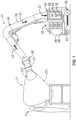
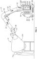
- FIG. 1 illustrates an extraction system 10 for extracting airborne components, such as smoke, fumes, particulate matter, and more generally, workspace air as indicated by reference numeral 12 from a work area 14.
- the extraction system 10 comprises a base unit 16 coupled to conduits 18 that channel air to and from a hood 20.
- the hood 20 is designed to be placed at or near (e.g., above) the work area 14 and, when the base unit 16 is activated, serves to create region of air around the area and to extract the workspace air, directing extracted air 12 to the base unit 16 for processing.
- a stand-alone base unit 16 or cart-type unit is described, the present disclosure is not limited to any particular physical configuration. More generally, systems and arrangements provided herein may be implemented as fixed or semi-fixed installations, such as those used in industrial, commercial, hobby, and other settings. That is, certain of the components of the base unit described herein may serve multiple workspaces, work cells, weld cells, work locations and areas, and so forth, by common conduits that direct positive-pressure air to and channel air and airborne components from one or more workspaces. Operator controls may be positioned at the work area and/or remotely from such workspaces to control operation of the system 10.
- airborne components evacuated from the work area 14 may be in an aerosol form, such as solid, liquid or gaseous phase particles that are suspended in air.
- airborne components may form smoke, fumes (including chemical fumes), or clouds of components generated by an operation performed in the area.
- the airborne components may be at least temporarily airborne but not suspended in the air, such as in the case of larger particulates, such as droplets, mist (e.g., from oils, coolants, and so forth), dust (e.g., from drywall, grain, minerals, cements, or other dust sources), chips, debris, and so forth.
- the system 10 is configured to collect and extract any such airborne components.
- air or "airborne”
- the fluid in which the airborne components are found and that is circulated by the system may be, more generally, a gaseous substance that need not contain the same constituents, or in the same ratios as found in atmospheric air.
- gasses are intended nevertheless be included in the term “air” or “airborne”.
- the same principles of fluid dynamics and borne component removal may be applied to other "fluids” than air or gasses (including liquids), and to that extent the teachings of the present disclosure are intended to extend to those applications.
- the base unit 16 includes a blower 22 driven by a drive motor 24.
- the drive motor 24 (as well as other functions of the extraction system 10) is controlled by control circuitry 26 which may provide drive signals to the motor for fixed-speed or variable-speed operation.
- the cart may best be designed with a small and highly efficient drive motor on the blower. In some examples, more than one motor and/or blower, fan or compressor may be used. The motor or motors may operate on a fixed speed or variable speeds.
- the base unit 16 may be designed to draw power from any source, such as the power grid, battery sources, engine-generator sets, and so forth.
- the control circuitry 26 typically includes processing circuitry and memory for carrying out drive operations as desired by the operator or in response to system inputs as described below.
- control circuitry 26 may communicate with an operator interface for receiving operator settings, speed settings, on-off commands, and so forth.
- control circuitry 26 may include and/or communicate with an interface (e.g., a remote interface) designed to receive signals from remote inputs, remote systems, and so forth.
- the control circuitry 26, via a remote interface, may also provide data to such remote systems such as sensors for monitoring and/or controlling operation of the extraction system 10.
- the conduits 18 extend between the base unit 16 and the hood 20, which may include a positive pressure air conduit and/or a return air conduit.
- the positive pressure air conduit provides air to the hood, while the return air conduit is under a negative or slight suction pressure to draw air containing the airborne components from the work area 14.
- the extracted air 12 returning from the hood 20 in conduit 18 may be directed through a filter 38.
- the air 12 may be reintroduced into the blower 22 as a semi-controlled system.
- the system may also include components designed to allow for adjustment of the individual or relative flow rates of one or both of the positive and negative pressure air streams.
- adjustment of the positive pressure air flow and/or the return air flow may be optimized for specific operations of the system.
- Several different techniques are presently contemplated for such adjustment and may include, for example, a bypass valve, a louver, or other mechanical device which may be adjusted to limit the flow of air from the suction filter and, consequently, the intake of air into the blower 22 from the ambient surroundings.
- Such adjustment may advantageously allow for relative mass or volumetric flow rates of the positive pressure and return airstreams to enhance creation of the air region and extraction of workspace air 204.
- user inputs may be provided via an operator interface to control one or both adjustments, communicated to the control circuitry 26 to regulate their operation (e.g., via small adjustment motors and/or actuator assemblies).
- adjustments to flow rates for the positive and negative pressure airstreams may be made by altering the speed of one or more motors and/or blowers, fans or compressors.
- other and additional components and functionalities may be built into the system.
- One or more support structures 48 are provided adjacent to the lower joint 42 or joint 44 to aid in supporting the arm as it is extended toward and/or retracted from a work area.
- the joints may include smooth inner walls that can be deformed so as to permit extension, retraction and, more generally, positioning of the conduits 18 with respect to the base unit 16, while adding little or no head loss as compared to a linear section of conduit.
- the base unit 16 has a filter 38 disposed in a filter enclosure or filter box 36.
- the filter enclosure 36 defines a region around or adjacent to the filter 38 from which air is drawn during operation of the system 10. That is, as disclosed herein, the returning or negative airstream enters the base unit 16, and this airstream, bearing the airborne components (e.g., debris, particles, etc.) enters into the region and then through an outer periphery of the filter 38.
- the filter medium is cylinder-like, but any suitable configuration may be used.
- the filter 38 is hollow, and is closed by a cap. Because debris may be released from the filter element during cleaning, the collection tray 28 is placed near a bottom region of the base unit 16 to allow the debris to be collected and/or separated from the filter element.
- return flow air 12 enters a filter enclosure 36 containing a filter 38, where the air 12 is filtered to remove particulate matter and other components borne by the airstream.
- the assembly may be designed for pressure cleaning, in a process that may direct pressurized air against one or more filter elements to promote the release of the captured particulate.
- air is drawn into the blower 22 which is driven by motor 24 as described above.
- multiple motors and/or blowers may be employed. For example, one motor and blower set may be used for the outgoing or positive air stream, while another motor and blower set may be used for the return or negative air stream.
- One or both air streams may be filtered by a common filter or dedicated filters.
- the system 10 may be equipped for filtering of components and debris from the air stream 12 returning to the base unit 16.
- this debris may collect in one or more filters, filter media, and/or filter elements 38 and/or the filter enclosure 36.
- the collected debris may be cleared or cleaned from the filter elements 38, such as by application of pressurized air (or other fluid), typically in pulses or puffs against the filter medium, as disclosed herein.
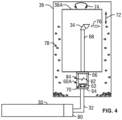
- a valve or other regulating device 80 may be arranged between the air compressor 30 and the conduit 32, which is in turn coupled to a chamber or housing 60.
- the valve 80 is manually, mechanically, and/or electronically controlled to initiate a pneumatic filter cleaning operation (e.g., in response to a sensor data, a control command, a change in pressure, and/or reaching a threshold pressure level).
- the chamber 60 encloses a movable guide 62 (e.g., extension guide), which is coupled to a second end of a conduit 68 supporting the nozzle 34 at a first end.
- a pressure at the nozzle 34 increases, forcing the nozzle 34 to extend away from the chamber 60.
- a threshold pressure level e.g., an adjustable or tunable pressure level
- a pulse of air 76 is released.
- the pulse of air 76 is directed toward a wall of the filter 38, forcing debris or other contaminants 78 to dislodge from the filter media.
- the debris may collect within the filter 38.
- the debris 78 may collect in a different portion of the system 10 (e.g., the collection tray 28) for removal.
- the groove 82 is configured to guide rotation of the guide 62, as shown by arrows 70, in response to linear movement 72 of the nozzle 34 and the guide. Due to the coupled relationship between the guide and the nozzle 34, the nozzle 34 experiences both linear (72) and rotational (74) movement, thus directing the pulsed air 74 at various locations of the filter 38.
- the nozzle 34 and the guide 62 move to a first position (e.g., full extension from the chamber 60) as pressure at the nozzle 34 increases.
- a threshold pressure level e.g., determined by a valve at the nozzle
- the pulsed air 74 is released, causing the pressure at the nozzle 34 to decrease, often rapidly.
- the nozzle 34 and the guide 62 change from the first position to a second position at or proximate to the chamber 60.
- a spring or other mechanism 62 is employed to bias the nozzle 34 toward the second position.
- one or more bumpers 64 and 66 can be included (e.g., within the chamber 60), which can limit or arrest movement of the guide 62.
- the groove 82 can be configured to control linear or rotational movement of the nozzle 34 and/or the guide 62 at variable rates and/or over variable positions, as is suitable for a particular application.
- following the groove 82 may force extension of the guide 62 to the first position at a first rate of movement (e.g., linearly or rotationally) in response to an increase in pressure at the nozzle.
- the groove 82 may force retraction of the guide 62 to the second position at a second rate, greater rate to force a shock or rapid impact, which may dislodge debris 78 from the filter 38.
- the nozzle 34 and/or the chamber 60 are offset from a center of the filter 38 and/or filter enclosure 36.
- the chamber 60 of the pneumatic filter cleaning device is configured to receive pressurized air and release a pulse of air when a pressure at the chamber 60 (or the nozzle 34) reaches a threshold pressure level.
- the chamber 60 is coupled to a second end of the conduit 68, which releases the pressurized air to the nozzle 34.
- the guide 62 is a bushing configured to slow or interrupt rotation of the nozzle 34 as the pulsed air drives the nozzle 34.
- the nozzle 34 may be directed at one or more angles relative to the surface of the filter 38.
- the bushing (which may support the conduit 68 and/or the chamber 60) may be configured to regulate rotation of the nozzle.
- the bushing may create friction between mated surfaces (of the bushing/guide 62, the chamber 60, and/or conduit 68), and/or may have a surface designed to regulate movement (e.g., a saw tooth pattern, an uneven surface, different materials with different friction coefficients, etc.).
Landscapes
- Chemical & Material Sciences (AREA)
- Chemical Kinetics & Catalysis (AREA)
- Filtering Of Dispersed Particles In Gases (AREA)
Claims (11)
- Dispositif de nettoyage de filtre de pneumatique pour un système d'extracteur d'air en suspension, caractérisé en ce que le dispositif de nettoyage de filtre de pneumatique comprend :une buse (34) arrimée sur une première extrémité d'un conduit (68) ; etune chambre (60) enfermant un guide mobile (62) couplé à une deuxième extrémité du conduit (68), dans lequel la buse (34) est configurée pour libérer une impulsion d'air (76) lorsqu'une pression au niveau de la chambre (60) ou de la buse (34) atteint un niveau de pression seuil,dans lequel le guide mobile (62) comprend une came ayant une rainure (82) appariée avec un poussoir arrimé sur une surface opposée de la chambre (60),dans lequel une augmentation de la pression au niveau de la buse (34) amène la came à tourner d'une première quantité par rapport au poussoir, forçant la buse (34) dans une première position par rapport à la chambre (60), etla libération de l'impulsion d'air (76) fait passer la pression au-dessous du niveau de pression seuil, ce qui entraîne ensuite la rotation de la came d'une deuxième quantité par rapport au poussoir, forçant la buse (34) dans une deuxième position par rapport à la chambre (60).
- Dispositif selon la revendication 1, dans lequel la première position correspond à une première distance de la buse (34) s'étendant à partir de la chambre (60) et de préférence dans lequel la deuxième position correspond à une deuxième distance de la buse (34) à partir de la chambre (60) suite à la libération de l'impulsion d'air (76), la deuxième distance étant inférieure à la première distance.
- Dispositif selon la revendication 1, dans lequel la rainure (82) est configurée pour guider la rotation du guide (62) lorsqu'un changement de pression au niveau de la buse (34) force la buse (34) à se déplacer de la première position à la deuxième position, le déplacement de la buse (34) provoquant le déplacement du guide mobile (62) ou dans lequel la came est configurée pour forcer l'extension du conduit (68) vers la première position à une première vitesse de déplacement en réponse à une augmentation de pression au niveau de la buse (34), et pour forcer la rétraction du conduit (68) vers la deuxième position à une deuxième vitesse de déplacement supérieure à la première vitesse en réponse à l'impulsion d'air (76).
- Dispositif selon la revendication 1, comprenant en outre un ressort configuré pour solliciter la buse (34) vers la deuxième position.
- Dispositif selon la revendication 1, comprenant en outre un butoir (64) au sein de la chambre (60) configuré pour limiter le mouvement du conduit (68).
- Dispositif selon la revendication 1, dans lequel l'air sous pression est fourni par un compresseur d'air (30) relié à la chambre (60) et de préférence dans lequel le transport de l'air sous pression depuis le compresseur d'air (30) est régulé par une vanne (80).
- Dispositif selon la revendication 1, dans lequel la buse (34) est orientée vers une surface d'un élément de filtre (38).
- Dispositif selon la revendication 1, dans lequel la buse (34) est une première buse (34A) agencée à une première position sur le conduit (68), le dispositif comprenant en outre une deuxième buse (34B) agencée à une deuxième position sur le conduit (68).
- Dispositif selon la revendication 1, comprenant en outre une vanne (80) configurée pour transporter de l'air sous pression jusque dans le dispositif de nettoyage de filtre en réponse à un signal de commande provenant d'une circuiterie de commande (22).
- Dispositif selon la revendication 9, comprenant en outre une circuiterie de commande (22) configurée pour :surveiller une ou plusieurs conditions de fonctionnement d'un milieu filtrant ;déterminer une valeur des une ou plusieurs conditions de fonctionnement ; etcomparer la valeur à une liste de valeurs de conditions de fonctionnement seuil.
- Dispositif selon la revendication 10, dans lequel la circuiterie de commande (22) est configurée pour commander la vanne (80) pour s'ouvrir afin de transporter de l'air sous pression en réponse à la valeur dépassant une première valeur de condition de fonctionnement seuil de la liste de valeurs de condition de fonctionnement seuil ou dans lequel la circuiterie de commande (22) est configurée pour générer une alerte en réponse à la valeur dépassant une deuxième valeur de condition de fonctionnement seuil de la liste de valeurs de condition de fonctionnement seuil ou dans lequel les une ou plusieurs conditions de fonctionnement comprennent une pression statique, un changement de pression, un débit d'air, un changement du débit d'air, une charge, une quantité de détritus collectée au niveau de l'élément filtrant, ou un temps d'utilisation du filtre.
Applications Claiming Priority (2)
| Application Number | Priority Date | Filing Date | Title |
|---|---|---|---|
| US202163149875P | 2021-02-16 | 2021-02-16 | |
| US17/668,817 US12605669B2 (en) | 2021-02-16 | 2022-02-10 | Systems and methods for pneumatic cleaning of an extraction system filter |
Publications (2)
| Publication Number | Publication Date |
|---|---|
| EP4043087A1 EP4043087A1 (fr) | 2022-08-17 |
| EP4043087B1 true EP4043087B1 (fr) | 2025-07-02 |
Family
ID=80735396
Family Applications (1)
| Application Number | Title | Priority Date | Filing Date |
|---|---|---|---|
| EP22157076.5A Active EP4043087B1 (fr) | 2021-02-16 | 2022-02-16 | Systèmes et procédés de nettoyage pneumatique d'un filtre de système d'extraction |
Country Status (3)
| Country | Link |
|---|---|
| US (1) | US12605669B2 (fr) |
| EP (1) | EP4043087B1 (fr) |
| CA (1) | CA3148957C (fr) |
Family Cites Families (15)
| Publication number | Priority date | Publication date | Assignee | Title |
|---|---|---|---|---|
| DE8304087U1 (de) * | 1983-02-14 | 1983-06-30 | Brückner Trockentechnik GmbH & Co KG, 7250 Leonberg | Vorrichtung zur umluftbehandlung von fortlaufend transportierten textilen warenbahnen, insbesondere spannrahmentrockner |
| US4491458A (en) * | 1983-03-28 | 1985-01-01 | The Air Preheater Company, Inc. | Method for detecting an overload of a fabric filter |
| GB8704582D0 (en) * | 1987-02-26 | 1987-04-01 | Dowty Mining Machinery Ltd | Fluid filtering systems |
| US5002594A (en) * | 1989-08-31 | 1991-03-26 | Ransburg Corporation | Filter pulse-down cartridge cleaning mechanism |
| US5228993A (en) * | 1990-02-09 | 1993-07-20 | Mordeki Drori | Cleanable filter system with longitudinally movable and rotatable cleaning member |
| DE4224100C2 (de) * | 1991-08-02 | 1997-06-05 | Barmag Barmer Maschf | Spulspindel |
| US5182832A (en) * | 1992-04-27 | 1993-02-02 | Mcmahon Michael R | Air filter cleaning apparatus |
| US5584900A (en) * | 1994-12-19 | 1996-12-17 | Zaiser; Gregory H. | Apparatus for cleaning cylindrical air filters |
| JP3108639B2 (ja) * | 1996-11-12 | 2000-11-13 | 核燃料サイクル開発機構 | サイクロン式集塵装置 |
| CA2286884A1 (fr) | 1998-10-19 | 2000-04-19 | Texas Electroniques Canada Inc. | Ensemble de gaines reglables pour l'evacuation de fumees et de poussieres et nettoyeur de filtre |
| KR100451550B1 (ko) * | 2002-08-13 | 2004-10-06 | 인천광역시(인천대학 총장) | 용적형 오일 펌프 |
| US20070107391A1 (en) | 2005-11-16 | 2007-05-17 | Christian Reining | Filtration device with a filter bag and a cleaning device for a filter bag |
| WO2009114128A1 (fr) * | 2008-03-10 | 2009-09-17 | Martin, Charles, E. | Filtre à écoulement radial avec dispositif de pulvérisation en déplacement |
| US8499409B2 (en) | 2008-10-08 | 2013-08-06 | Christian Reining | Cleaning device comprising a cleaning head and method for cleaning hose-type tube filters |
| US11724225B2 (en) * | 2019-06-26 | 2023-08-15 | Gita Green, Inc. | Filtering medium cleaning apparatus and method |
-
2022
- 2022-02-10 US US17/668,817 patent/US12605669B2/en active Active
- 2022-02-15 CA CA3148957A patent/CA3148957C/fr active Active
- 2022-02-16 EP EP22157076.5A patent/EP4043087B1/fr active Active
Also Published As
| Publication number | Publication date |
|---|---|
| US20220258092A1 (en) | 2022-08-18 |
| EP4043087A1 (fr) | 2022-08-17 |
| US12605669B2 (en) | 2026-04-21 |
| CA3148957C (fr) | 2024-02-27 |
| CA3148957A1 (fr) | 2022-08-16 |
Similar Documents
| Publication | Publication Date | Title |
|---|---|---|
| US9505041B2 (en) | Optimized airborne component extractor | |
| CN105339100B (zh) | 用挡板收集碎屑的空气承载成分抽出器 | |
| MX2015004985A (es) | Sistema de evacuacion de emanaciones. | |
| EP4043087B1 (fr) | Systèmes et procédés de nettoyage pneumatique d'un filtre de système d'extraction | |
| EP4529972B1 (fr) | Systèmes et procédés d'élimination de filtre et/ou de débris pour un filtre de système d'extraction |
Legal Events
| Date | Code | Title | Description |
|---|---|---|---|
| PUAI | Public reference made under article 153(3) epc to a published international application that has entered the european phase |
Free format text: ORIGINAL CODE: 0009012 |
|
| STAA | Information on the status of an ep patent application or granted ep patent |
Free format text: STATUS: THE APPLICATION HAS BEEN PUBLISHED |
|
| AK | Designated contracting states |
Kind code of ref document: A1 Designated state(s): AL AT BE BG CH CY CZ DE DK EE ES FI FR GB GR HR HU IE IS IT LI LT LU LV MC MK MT NL NO PL PT RO RS SE SI SK SM TR |
|
| STAA | Information on the status of an ep patent application or granted ep patent |
Free format text: STATUS: REQUEST FOR EXAMINATION WAS MADE |
|
| 17P | Request for examination filed |
Effective date: 20230214 |
|
| RBV | Designated contracting states (corrected) |
Designated state(s): AL AT BE BG CH CY CZ DE DK EE ES FI FR GB GR HR HU IE IS IT LI LT LU LV MC MK MT NL NO PL PT RO RS SE SI SK SM TR |
|
| STAA | Information on the status of an ep patent application or granted ep patent |
Free format text: STATUS: EXAMINATION IS IN PROGRESS |
|
| 17Q | First examination report despatched |
Effective date: 20230721 |
|
| GRAP | Despatch of communication of intention to grant a patent |
Free format text: ORIGINAL CODE: EPIDOSNIGR1 |
|
| STAA | Information on the status of an ep patent application or granted ep patent |
Free format text: STATUS: GRANT OF PATENT IS INTENDED |
|
| INTG | Intention to grant announced |
Effective date: 20250225 |
|
| GRAS | Grant fee paid |
Free format text: ORIGINAL CODE: EPIDOSNIGR3 |
|
| GRAA | (expected) grant |
Free format text: ORIGINAL CODE: 0009210 |
|
| STAA | Information on the status of an ep patent application or granted ep patent |
Free format text: STATUS: THE PATENT HAS BEEN GRANTED |
|
| P01 | Opt-out of the competence of the unified patent court (upc) registered |
Free format text: CASE NUMBER: APP_21049/2025 Effective date: 20250502 |
|
| AK | Designated contracting states |
Kind code of ref document: B1 Designated state(s): AL AT BE BG CH CY CZ DE DK EE ES FI FR GB GR HR HU IE IS IT LI LT LU LV MC MK MT NL NO PL PT RO RS SE SI SK SM TR |
|
| REG | Reference to a national code |
Ref country code: GB Ref legal event code: FG4D |
|
| REG | Reference to a national code |
Ref country code: CH Ref legal event code: EP |
|
| REG | Reference to a national code |
Ref country code: DE Ref legal event code: R096 Ref document number: 602022016658 Country of ref document: DE |
|
| REG | Reference to a national code |
Ref country code: IE Ref legal event code: FG4D |
|
| REG | Reference to a national code |
Ref country code: NL Ref legal event code: MP Effective date: 20250702 |
|
| PG25 | Lapsed in a contracting state [announced via postgrant information from national office to epo] |
Ref country code: PT Free format text: LAPSE BECAUSE OF FAILURE TO SUBMIT A TRANSLATION OF THE DESCRIPTION OR TO PAY THE FEE WITHIN THE PRESCRIBED TIME-LIMIT Effective date: 20251103 |
|
| PG25 | Lapsed in a contracting state [announced via postgrant information from national office to epo] |
Ref country code: NL Free format text: LAPSE BECAUSE OF FAILURE TO SUBMIT A TRANSLATION OF THE DESCRIPTION OR TO PAY THE FEE WITHIN THE PRESCRIBED TIME-LIMIT Effective date: 20250702 |
|
| REG | Reference to a national code |
Ref country code: AT Ref legal event code: MK05 Ref document number: 1808647 Country of ref document: AT Kind code of ref document: T Effective date: 20250702 |
|
| PG25 | Lapsed in a contracting state [announced via postgrant information from national office to epo] |
Ref country code: IS Free format text: LAPSE BECAUSE OF FAILURE TO SUBMIT A TRANSLATION OF THE DESCRIPTION OR TO PAY THE FEE WITHIN THE PRESCRIBED TIME-LIMIT Effective date: 20251102 |
|
| PG25 | Lapsed in a contracting state [announced via postgrant information from national office to epo] |
Ref country code: NO Free format text: LAPSE BECAUSE OF FAILURE TO SUBMIT A TRANSLATION OF THE DESCRIPTION OR TO PAY THE FEE WITHIN THE PRESCRIBED TIME-LIMIT Effective date: 20251002 |
|
| REG | Reference to a national code |
Ref country code: LT Ref legal event code: MG9D |
|
| PG25 | Lapsed in a contracting state [announced via postgrant information from national office to epo] |
Ref country code: AT Free format text: LAPSE BECAUSE OF FAILURE TO SUBMIT A TRANSLATION OF THE DESCRIPTION OR TO PAY THE FEE WITHIN THE PRESCRIBED TIME-LIMIT Effective date: 20250702 |
|
| PG25 | Lapsed in a contracting state [announced via postgrant information from national office to epo] |
Ref country code: FI Free format text: LAPSE BECAUSE OF FAILURE TO SUBMIT A TRANSLATION OF THE DESCRIPTION OR TO PAY THE FEE WITHIN THE PRESCRIBED TIME-LIMIT Effective date: 20250702 |
|
| PG25 | Lapsed in a contracting state [announced via postgrant information from national office to epo] |
Ref country code: HR Free format text: LAPSE BECAUSE OF FAILURE TO SUBMIT A TRANSLATION OF THE DESCRIPTION OR TO PAY THE FEE WITHIN THE PRESCRIBED TIME-LIMIT Effective date: 20250702 |
|
| PG25 | Lapsed in a contracting state [announced via postgrant information from national office to epo] |
Ref country code: GR Free format text: LAPSE BECAUSE OF FAILURE TO SUBMIT A TRANSLATION OF THE DESCRIPTION OR TO PAY THE FEE WITHIN THE PRESCRIBED TIME-LIMIT Effective date: 20251003 |
|
| PG25 | Lapsed in a contracting state [announced via postgrant information from national office to epo] |
Ref country code: SE Free format text: LAPSE BECAUSE OF FAILURE TO SUBMIT A TRANSLATION OF THE DESCRIPTION OR TO PAY THE FEE WITHIN THE PRESCRIBED TIME-LIMIT Effective date: 20250702 Ref country code: CZ Free format text: LAPSE BECAUSE OF FAILURE TO SUBMIT A TRANSLATION OF THE DESCRIPTION OR TO PAY THE FEE WITHIN THE PRESCRIBED TIME-LIMIT Effective date: 20250702 |
|
| PG25 | Lapsed in a contracting state [announced via postgrant information from national office to epo] |
Ref country code: LV Free format text: LAPSE BECAUSE OF FAILURE TO SUBMIT A TRANSLATION OF THE DESCRIPTION OR TO PAY THE FEE WITHIN THE PRESCRIBED TIME-LIMIT Effective date: 20250702 |
|
| PG25 | Lapsed in a contracting state [announced via postgrant information from national office to epo] |
Ref country code: PL Free format text: LAPSE BECAUSE OF FAILURE TO SUBMIT A TRANSLATION OF THE DESCRIPTION OR TO PAY THE FEE WITHIN THE PRESCRIBED TIME-LIMIT Effective date: 20250702 Ref country code: BG Free format text: LAPSE BECAUSE OF FAILURE TO SUBMIT A TRANSLATION OF THE DESCRIPTION OR TO PAY THE FEE WITHIN THE PRESCRIBED TIME-LIMIT Effective date: 20250702 |
|
| PG25 | Lapsed in a contracting state [announced via postgrant information from national office to epo] |
Ref country code: RS Free format text: LAPSE BECAUSE OF FAILURE TO SUBMIT A TRANSLATION OF THE DESCRIPTION OR TO PAY THE FEE WITHIN THE PRESCRIBED TIME-LIMIT Effective date: 20251002 |
|
| PG25 | Lapsed in a contracting state [announced via postgrant information from national office to epo] |
Ref country code: ES Free format text: LAPSE BECAUSE OF FAILURE TO SUBMIT A TRANSLATION OF THE DESCRIPTION OR TO PAY THE FEE WITHIN THE PRESCRIBED TIME-LIMIT Effective date: 20250702 |
|
| PG25 | Lapsed in a contracting state [announced via postgrant information from national office to epo] |
Ref country code: SM Free format text: LAPSE BECAUSE OF FAILURE TO SUBMIT A TRANSLATION OF THE DESCRIPTION OR TO PAY THE FEE WITHIN THE PRESCRIBED TIME-LIMIT Effective date: 20250702 |
|
| PG25 | Lapsed in a contracting state [announced via postgrant information from national office to epo] |
Ref country code: DK Free format text: LAPSE BECAUSE OF FAILURE TO SUBMIT A TRANSLATION OF THE DESCRIPTION OR TO PAY THE FEE WITHIN THE PRESCRIBED TIME-LIMIT Effective date: 20250702 |
|
| PGFP | Annual fee paid to national office [announced via postgrant information from national office to epo] |
Ref country code: DE Payment date: 20260227 Year of fee payment: 5 |
|
| PGFP | Annual fee paid to national office [announced via postgrant information from national office to epo] |
Ref country code: IT Payment date: 20260219 Year of fee payment: 5 |
|
| PG25 | Lapsed in a contracting state [announced via postgrant information from national office to epo] |
Ref country code: EE Free format text: LAPSE BECAUSE OF FAILURE TO SUBMIT A TRANSLATION OF THE DESCRIPTION OR TO PAY THE FEE WITHIN THE PRESCRIBED TIME-LIMIT Effective date: 20250702 Ref country code: SK Free format text: LAPSE BECAUSE OF FAILURE TO SUBMIT A TRANSLATION OF THE DESCRIPTION OR TO PAY THE FEE WITHIN THE PRESCRIBED TIME-LIMIT Effective date: 20250702 |