EP4043655A1 - Ensemble pied et dispositif de montage comprenant un tel ensemble pied - Google Patents
Ensemble pied et dispositif de montage comprenant un tel ensemble pied Download PDFInfo
- Publication number
- EP4043655A1 EP4043655A1 EP21156806.8A EP21156806A EP4043655A1 EP 4043655 A1 EP4043655 A1 EP 4043655A1 EP 21156806 A EP21156806 A EP 21156806A EP 4043655 A1 EP4043655 A1 EP 4043655A1
- Authority
- EP
- European Patent Office
- Prior art keywords
- foot
- support
- foot unit
- pivot axis
- mounting device
- Prior art date
- Legal status (The legal status is an assumption and is not a legal conclusion. Google has not performed a legal analysis and makes no representation as to the accuracy of the status listed.)
- Granted
Links
Images


Classifications
-
- E—FIXED CONSTRUCTIONS
- E03—WATER SUPPLY; SEWERAGE
- E03D—WATER-CLOSETS OR URINALS WITH FLUSHING DEVICES; FLUSHING VALVES THEREFOR
- E03D11/00—Other component parts of water-closets, e.g. noise-reducing means in the flushing system, flushing pipes mounted in the bowl, seals for the bowl outlet, devices preventing overflow of the bowl contents; devices forming a water seal in the bowl after flushing, devices eliminating obstructions in the bowl outlet or preventing backflow of water and excrements from the waterpipe
- E03D11/13—Parts or details of bowls; Special adaptations of pipe joints or couplings for use with bowls, e.g. provisions in bowl construction preventing backflow of waste-water from the bowl in the flushing pipe or cistern, provisions for a secondary flushing, for noise-reducing
- E03D11/14—Means for connecting the bowl to the wall, e.g. to a wall outlet
- E03D11/143—Mounting frames for toilets and urinals
- E03D11/146—Mounting frames for toilets and urinals with incorporated cistern
-
- E—FIXED CONSTRUCTIONS
- E03—WATER SUPPLY; SEWERAGE
- E03D—WATER-CLOSETS OR URINALS WITH FLUSHING DEVICES; FLUSHING VALVES THEREFOR
- E03D11/00—Other component parts of water-closets, e.g. noise-reducing means in the flushing system, flushing pipes mounted in the bowl, seals for the bowl outlet, devices preventing overflow of the bowl contents; devices forming a water seal in the bowl after flushing, devices eliminating obstructions in the bowl outlet or preventing backflow of water and excrements from the waterpipe
- E03D11/13—Parts or details of bowls; Special adaptations of pipe joints or couplings for use with bowls, e.g. provisions in bowl construction preventing backflow of waste-water from the bowl in the flushing pipe or cistern, provisions for a secondary flushing, for noise-reducing
-
- E—FIXED CONSTRUCTIONS
- E03—WATER SUPPLY; SEWERAGE
- E03D—WATER-CLOSETS OR URINALS WITH FLUSHING DEVICES; FLUSHING VALVES THEREFOR
- E03D1/00—Water flushing devices with cisterns ; Setting up a range of flushing devices or water-closets; Combinations of several flushing devices
- E03D1/01—Shape or selection of material for flushing cisterns
- E03D1/012—Details of shape of cisterns, e.g. for connecting to wall, for supporting or connecting flushing-device actuators
-
- E—FIXED CONSTRUCTIONS
- E03—WATER SUPPLY; SEWERAGE
- E03D—WATER-CLOSETS OR URINALS WITH FLUSHING DEVICES; FLUSHING VALVES THEREFOR
- E03D11/00—Other component parts of water-closets, e.g. noise-reducing means in the flushing system, flushing pipes mounted in the bowl, seals for the bowl outlet, devices preventing overflow of the bowl contents; devices forming a water seal in the bowl after flushing, devices eliminating obstructions in the bowl outlet or preventing backflow of water and excrements from the waterpipe
- E03D11/13—Parts or details of bowls; Special adaptations of pipe joints or couplings for use with bowls, e.g. provisions in bowl construction preventing backflow of waste-water from the bowl in the flushing pipe or cistern, provisions for a secondary flushing, for noise-reducing
- E03D11/135—Supports for bowls
-
- E—FIXED CONSTRUCTIONS
- E03—WATER SUPPLY; SEWERAGE
- E03D—WATER-CLOSETS OR URINALS WITH FLUSHING DEVICES; FLUSHING VALVES THEREFOR
- E03D11/00—Other component parts of water-closets, e.g. noise-reducing means in the flushing system, flushing pipes mounted in the bowl, seals for the bowl outlet, devices preventing overflow of the bowl contents; devices forming a water seal in the bowl after flushing, devices eliminating obstructions in the bowl outlet or preventing backflow of water and excrements from the waterpipe
- E03D11/13—Parts or details of bowls; Special adaptations of pipe joints or couplings for use with bowls, e.g. provisions in bowl construction preventing backflow of waste-water from the bowl in the flushing pipe or cistern, provisions for a secondary flushing, for noise-reducing
- E03D11/14—Means for connecting the bowl to the wall, e.g. to a wall outlet
- E03D11/143—Mounting frames for toilets and urinals
Definitions
- the present invention relates to a foot unit for a sanitary mounting device for attaching at least one sanitary item according to claim 1 and a mounting device according to claim 11.
- Mounting devices for fastening sanitary articles are known from the prior art. Such mounting devices are permanently installed behind a pretext and are used to store sanitary articles, such as cisterns, toilet bowls, urinals, fittings, sinks, control elements, electrical elements, etc.
- sanitary articles such as cisterns, toilet bowls, urinals, fittings, sinks, control elements, electrical elements, etc.
- EP 2 662 502 such a mounting device.
- a mounting device with a footrest has become known.
- the footrest can be inserted into a hollow profile in positions offset by 90°.
- the entire footrest must be pulled out of the hollow profile and reinserted. Alignment of the footrests is very laborious and complicated, especially when space is tight.
- the invention is based on an object Specify foot unit for a sanitary mounting device, which overcomes the disadvantages of the prior art.
- it is an object of the present invention to specify a foot unit for a sanitary mounting device which can be more easily adapted to given structures.
- the foot unit is provided for a sanitary assembly device, which in turn is used to store sanitary elements.
- the foot unit comprises a connecting element with a connecting section for connecting the foot unit to the mounting device and a foot element with a bearing surface with which the foot element can be supported on a carrier structure.
- the connecting element and the foot element are connected to one another via a swivel joint.
- the swivel joint has a swivel section on the foot element side and a swivel section on the connecting element side, which swivel sections are in each case pivotably engaged with one another.
- the foot element can be pivoted via the pivot joint about a pivot axis relative to the stationary connecting element between a first position and a second position.
- the arrangement of the swivel joint allows the possibility of a simple adjustment of the foot element to given structures.
- This means that the pivoting of the footrest allows easy adaptation to the structures provided by the customer. By simply pivoting, it can be achieved that in the event of a possible collision of the foot element with fixed structures, for example the support structure, it can be avoided by pivoting the foot element accordingly.
- the foot element can also be adapted to different support structures by pivoting.
- the support structure is, for example, a profile rail or the floor of a building.
- the swivel joint is preferably designed in such a way that the adjustment can be carried out without tools. This means that the pivoting can be done by hand without using a tool.
- the pivot axis is oriented substantially at right angles to said bearing surface. Seen in the installed position, the pivot axis runs essentially in the vertical. Preferably, the pivoting angle between the first position and the second position is between 45° and 360°. The pivoting angle is particularly preferably 90° or a multiple of 90°.
- the foot element preferably has a first pair of side faces and a second pair of side faces, with the two side faces of each pair of side faces being parallel and spaced apart from one another.
- the pivot axis is offset laterally to the center between the two side surfaces.
- the pivot axis is offset laterally to the middle between two opposite side surfaces and in the middle between the other two opposite side surfaces.
- the side surfaces can also be referred to as stop surfaces.
- the side faces can hit the side walls of a profile or the wall of a building.
- the foot element has an upper side where the pivoting section on the foot element side is arranged.
- the foot element is designed like a plate.
- the swivel joint preferably has a first stop and a further stop, with the foot element being able to swivel between the two stops.
- the foot element is in said first position when the foot element strikes the first stop and in said second position when the foot element strikes the second stop.
- the two stops are in such a way that the pivoting angle described above can be achieved.
- Said stops are preferably each provided with a stop section on the foot element side and a stop section on the connecting element side.
- the two stop sections each form the stop.
- the pivot joint by a cylinder pin with a circular-cylindrical outer surface extending around the pivot axis and a cylinder opening with a circular-cylindrical inner surface extending around the pivot axis, the outer surface being in contact with the inner surface and the outer surface and inner surface sliding relative to one another during the pivoting movement.
- the cylinder hole is the link-side pivot portion.
- the cylinder hole is the base-side pivot portion.
- the pivot joint is provided by an outer sphere having a part-spherical outer surface and an inner sphere having a part-spherical inner surface, the outer surface being in contact with the inner surface, and during pivoting movement, the outer surface and inner surface sliding relative to one another.
- the inner sphere is the pivoting portion on the link member side.
- the inner sphere is the base-side pivoting portion.
- the connecting section is preferably provided by a hollow profile which can be connected to the sanitary mounting device; or which is provided by the sanitary fixture.
- the hollow profile preferably has a square cross section and the pivot axis runs parallel and laterally offset to the central axis of the hollow profile.
- the side surfaces of the foot unit preferably run parallel to the side surfaces of the hollow profile in the first layer and the second layer.
- the hollow profile is preferably arranged in a corner of two side surfaces and is at a distance of 0 to 5 millimeters from the two side surfaces.
- the swivel joint has a latching structure which upon reaching the first position and/or when the second position is reached, locking between the foot element and the connecting element is provided.
- the installer can be given haptic feedback when the first or second position is reached. Furthermore, the foot element is held in the first or second position.
- the foot part preferably includes a through-opening for passing through a fastening screw.
- a mounting device for attaching at least one sanitary item comprises two spaced-apart supports designed as hollow profiles, which each extend along a central axis, and at least one crossbar which is firmly connected to the supports and connects the supports to one another, and wherein one foot unit is arranged per support according to the above description.
- the foot unit is preferably connected to the respective support with the connecting section.
- the support itself can also provide the connection section.
- the pivot axis is preferably positioned relative to the support in such a way that at least two adjoining side faces are flush with at least one outside of the support or are essentially flush with at least one outside of the support both in the first position and in the second position.
- the supports preferably span a front plane with their front surfaces, on which a planking arrangement can be arranged.
- the pivot axis is supported in such a way that the foot element does not penetrate the front plane either in the first position or in the second position. Accordingly, the foot element does not extend through the front plane. This means that the foot element lies behind the front plane in every position with regard to the planking arrangement. In this respect, there is no collision of the planking arrangement with the foot element.
- the supports each have a side surface lying on the outside, with the pivot axis being positioned relative to the support in such a way that the foot element is flush or substantially flush with said side surface both in the first position and in the second position.
- the side surface lying on the outside lies on the outside of the support, i.e. on the side facing away from the other support.
- the connecting element and the connecting section are preferably an integral part of the support.
- the foot unit projects into the support with the connecting section.
- the support has a square cross-section and the pivot axis is parallel to and laterally offset from the central axis of the support.
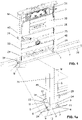
- 1a , 2 and 2a are perspective views of an assembly device 2 shown.
- the assembly device 2 comprises two supports 28 which are arranged at a distance from one another and which are connected to one another via at least one traverse 44 .
- a lower traverse, a middle traverse and an upper traverse are arranged.
- the lower crosshead is typically provided as a compression crosshead and the middle crosshead is typically provided as a tension crosshead.
- a toilet bowl, for example, can be stored on the pressure traverse and the tension traverse.
- a cistern 30 with corresponding actuating elements 31 is arranged between the middle cross member and the upper cross member in the variant shown.
- the assembly device 2 can also be used to store other sanitary elements.
- Each of the two supports 28 has a foot unit 1 .
- the mounting device 2 can be supported on a support structure 7 via the foot unit 1 .
- a profile element 32 is thereby provided for the support structure 7 .
- the profile element 32 has the shape of a U-profile.
- the support structure 7 can also be provided by a floor of a supporting structure, such as a building.
- the foot unit 1 comprises a connecting element 3 and a foot element 5 .
- the foot element 5 can be pivoted relative to the connecting element 3 .
- the connecting element 3 is connected to the support 28 or is provided by the support 28 .
- the foot element 5 can be pivoted from a first position into a second position relative to the stationary connecting element 3 or relative to the respective support 28 .
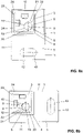
- the foot element 5 is shown in the first position and in the Figures 2 and 2a the foot element 5 is shown in the second position.
- a wider profile element 32 used than in the Figures 2 and 2a As shown by the figures, in the variant according to the Figures 1 and 1a a wider profile element 32 used than in the Figures 2 and 2a .
- the pivotability of the foot element 5 means that the foot unit 1 can be adapted to the conditions specified by the support structure 7 .
- the front surfaces 33 of the two supports 28 span a front plane.
- a paneling arrangement can be arranged on this front plane or on the front surfaces 33 .
- the foot elements 5 can be swiveled in such a way that the foot elements 5 do not penetrate the front plane or extend beyond the two front surfaces 33 either in the first position or in the second position. In this way it can be achieved that there is no collision between the foot elements 5 and planking.
- the pivot axis is such that the side surfaces of the foot element 5 are flush with an outer side surface 45 of the support in the first and the second position.
- FIGS 3 to 5b show a first embodiment of the foot unit 1 according to the present invention
- the Figures 6 to 8b show a second embodiment of the foot unit 1 according to the present invention. Based on Figures 3 to 8b the foot unit 1 will now be explained in detail. In the two embodiments, the same parts are provided with the same reference numbers and reference is made to the respective description.
- the foot unit 1 comprises a connecting element 3 with a connecting section 4 for connecting the foot unit 1 to the mounting device 2 and a foot element 5 with a bearing surface 6, with which the foot element 5 can be supported on the carrier structure 7.
- the bearing surface 6 extends horizontally in the installed position.
- the connecting element 3 and the foot element 5 are connected to one another via a swivel joint 8 .
- the foot element 5 can be pivoted relative to the connecting element 3 from the first position into the second position and from the second position back into the first position via the pivot joint 8 .
- the swivel joint 8 comprises a swivel section 9 on the foot element side and a swivel section 10 on the connecting element side.
- the two swivel sections 9, 10 are connected to one another.
- the pivoting sections 9, 10 can be pivoted relative to one another.
- the foot element 5 can be pivoted about a pivot axis S relative to the stationary connecting element 3 via the pivot joint 8 .
- the pivot axis S is essentially at right angles to the support surface 6 and runs essentially parallel to the central axis M of the supports 28. Viewed in the installed position, the pivot axis S runs in the vertical.
- pivoting angle between the first position and the second position is 90° in the embodiment shown.
- Other Pivot angles are also conceivable.
- the foot element 5 is designed as a foot plate.
- the foot element 5 has a first pair of side surfaces 11 and a second pair of side surfaces 12 .
- the side faces 11 of one pair are parallel and spaced from each other and the side faces 12 of the other pair are also parallel and spaced from each other.
- the side surfaces 11 and the side surfaces 12 are each at a right angle to one another.
- the side faces 11, 12 extend at right angles to the bearing surface 6 with respect to the bearing surface 6.
- the foot element 5 has an upper side 34 on the upper side.
- the pivoting section 9 on the side of the foot element is arranged on the upper side 34 in each case.
- the foot element 5 has the shape of a rectangle when viewed from above.
- the side surfaces 11 are the side surfaces of the broad side of the rectangle and the side surfaces 12 are the side surfaces of the narrow side of the rectangle. In other variants, it would also be conceivable for the side faces to be at a different angle to one another.
- the pivot axis S is centered between the two side surfaces 11 and laterally offset from the center between the two side surfaces 12. In other words, the pivot axis S is offset from the center of the footplate.
- the swivel joint 8 has a first stop 13 and a second stop 14 .
- the first stop 13 and the second stop 14 each provide a stop for the foot element 5 in the first or second position. This means that the foot element 5 can be pivoted between the two stops 13 , 14 .
- each of the stops 13, 14 has a stop section on the foot element side and a stop section on the connecting element side.
- the pivot joint 8 is provided by a cylinder pin 15 and a cylinder hole 17 .
- the pivoting section 9 on the foot element side is designed as a cylinder pin 15 and the pivoting section 10 on the connecting element side is designed as a cylinder opening 17 .
- the cylinder pin 15 has an outer surface 16 extending around the pivot axis S.
- the cylinder opening 17 has a pivot axis S extending around Inner surface 18 on. The outer surface 16 slides further pivoting movement relative to the inner surface 18 .
- the connecting section 4 is provided by a hollow profile 23 .
- An insert element 36 is mounted in the hollow profile 23, in which the pivoting section 10 on the connecting element side is formed.
- the insert element 36 is fixed here via a screw 37 on the hollow profile 23 .
- Said swivel joint 8 is inside the hollow profile 23.
- the insert element 36 comprises the stop section of the two stops on the connecting element side.
- a recess 38 extends from the side of the insert element 36 to the cylinder opening 17.
- the recess 38 is essentially used for easy installation of the insert element 36 on the pivoting section 9 on the foot element side.
- a flange section 39 extends from the Outer surface 16 away. This flange section 39 engages in a correspondingly designed recess 40 which extends laterally to the cylinder opening 17 . The engagement between the flange section 39 and the recess 40 means that the foot element 5 and the connecting element 3 cannot separate in the direction of the pivot axis S in the connected state.
- the pivot joint 8 is provided by an outer ball 19 having a partially spherical outer surface 20 and an inner ball 21 having a partially spherical inner surface 22 .
- the outer surface 20 is in contact with the inner surface 22 and during the pivoting movement the outer surface 20 and the inner surface 21 slide relative to one another.
- the outer sphere 19 is formed with incisions 41 .
- the incisions 41 allow the outer sphere 19 to snap over the inner sphere 21 during assembly.
- the stops 13 , 14 are provided by a comb 42 which is arranged on the outer sphere 19 and by correspondingly designed stop structures in the inner sphere 21 .
- the swivel joint 8 also has a latching structure 25.
- the latching structure 25 is arranged in such a way that when the first position is reached and/or when the second position is reached, a latching between the foot element 5 and the connecting element 3 provided.
- the locking structure is designed as a locking element 26 which is arranged on the connecting element 3 and as a corresponding locking recess 27 which is arranged on the foot element 5 .
- the latching element 26 engages in the latching recess 27 .
- the latching element 26 is preferably spring-loaded and engages in the latching recess 27 which is arranged on the outside of the flange section 39 .
- the connecting section 4 is provided by a hollow profile 23 in the embodiment shown.
- the hollow profile 23 protrudes from below into the respective support 28 and is connected to the support 28 there.
- the foot unit 1 can be arranged at different heights. It will be on the Figures 1 to 2a referred.
- Said side surfaces 11, 12 are parallel to the outer sides of the hollow profile 23.
- Two side surfaces 11, 12 are particularly preferably arranged essentially flush with the outer side 29 of the supports 28 and at a distance from the thickness of the support profile to the outer side 24 of the hollow profile 23.
- the foot element 5 also has an opening 43 through which a screw can be passed for attachment to the support structure.
Landscapes
- Health & Medical Sciences (AREA)
- Life Sciences & Earth Sciences (AREA)
- Engineering & Computer Science (AREA)
- Hydrology & Water Resources (AREA)
- Public Health (AREA)
- Water Supply & Treatment (AREA)
- Toilet Supplies (AREA)
Priority Applications (2)
| Application Number | Priority Date | Filing Date | Title |
|---|---|---|---|
| EP21156806.8A EP4043655B1 (fr) | 2021-02-12 | 2021-02-12 | Ensemble pied et dispositif de montage comprenant un tel ensemble pied |
| CN202210070523.8A CN114922267A (zh) | 2021-02-12 | 2022-01-21 | 脚单元和安装装置 |
Applications Claiming Priority (1)
| Application Number | Priority Date | Filing Date | Title |
|---|---|---|---|
| EP21156806.8A EP4043655B1 (fr) | 2021-02-12 | 2021-02-12 | Ensemble pied et dispositif de montage comprenant un tel ensemble pied |
Publications (2)
| Publication Number | Publication Date |
|---|---|
| EP4043655A1 true EP4043655A1 (fr) | 2022-08-17 |
| EP4043655B1 EP4043655B1 (fr) | 2024-06-05 |
Family
ID=74595136
Family Applications (1)
| Application Number | Title | Priority Date | Filing Date |
|---|---|---|---|
| EP21156806.8A Active EP4043655B1 (fr) | 2021-02-12 | 2021-02-12 | Ensemble pied et dispositif de montage comprenant un tel ensemble pied |
Country Status (2)
| Country | Link |
|---|---|
| EP (1) | EP4043655B1 (fr) |
| CN (1) | CN114922267A (fr) |
Citations (7)
| Publication number | Priority date | Publication date | Assignee | Title |
|---|---|---|---|---|
| US2810917A (en) * | 1952-07-29 | 1957-10-29 | J A Zurn Mfg Co | Lavatory carrier |
| DE1803775A1 (de) * | 1967-10-26 | 1969-06-19 | Ankarsrums Bruk Ab | Stuezenvorrichtung fuer eine Badewanne |
| EP1659229A2 (fr) | 2004-10-22 | 2006-05-24 | VIEGA GmbH & Co. KG. | Pied de montage et élément sanitaire |
| DE202006011801U1 (de) * | 2006-08-01 | 2006-09-28 | Mayr, Frank | Rahmenkonstruktion für die Montage eines Sanitärgegenstandes |
| EP2662502A1 (fr) | 2012-05-09 | 2013-11-13 | Geberit International AG | Dispositif de montage destiné à la fixation dýun appareil sanitaire |
| EP2740849A1 (fr) * | 2011-09-21 | 2014-06-11 | Fominaya, S.A. | Châssis encastrable destiné à fixer des éléments sanitaires et procédé de fabrication correspondant |
| WO2020220059A1 (fr) * | 2019-04-29 | 2020-11-05 | Christian Micheluzzi | Châssis de montage servant au montage d'un receveur de douche à niveau avec le sol |
Family Cites Families (6)
| Publication number | Priority date | Publication date | Assignee | Title |
|---|---|---|---|---|
| DE19929497A1 (de) * | 1999-06-28 | 2001-01-04 | Correcta Gmbh | Mit einem Vorwandelement verbundener Wannenträger |
| JP4062914B2 (ja) * | 2001-12-14 | 2008-03-19 | Sus株式会社 | フットコネクタ |
| EP2789931B1 (fr) * | 2013-04-12 | 2020-08-12 | Renusol Europe GmbH | Dispositif de maintien pour la fixation d'un module de surface sur un support |
| DE102014222325A1 (de) * | 2014-10-31 | 2016-05-04 | Hünnebeck GmbH | Höhenverstellbares Fußstück als Bestandteil eines Gerüsts sowie Gerüst mit einem solchen |
| EP3067477B1 (fr) * | 2015-03-11 | 2019-05-08 | Raccords et Plastiques Nicoll | Dispositif de fixation pour bâti support, ensemble de fixation comprenant un tel dispositif et procédé de fixation sur un bâti support |
| CN210151844U (zh) * | 2019-02-18 | 2020-03-17 | 厦门瑞尔特卫浴科技股份有限公司 | 一种隐藏式水箱的安装架及具有其的卫生设备 |
-
2021
- 2021-02-12 EP EP21156806.8A patent/EP4043655B1/fr active Active
-
2022
- 2022-01-21 CN CN202210070523.8A patent/CN114922267A/zh active Pending
Patent Citations (7)
| Publication number | Priority date | Publication date | Assignee | Title |
|---|---|---|---|---|
| US2810917A (en) * | 1952-07-29 | 1957-10-29 | J A Zurn Mfg Co | Lavatory carrier |
| DE1803775A1 (de) * | 1967-10-26 | 1969-06-19 | Ankarsrums Bruk Ab | Stuezenvorrichtung fuer eine Badewanne |
| EP1659229A2 (fr) | 2004-10-22 | 2006-05-24 | VIEGA GmbH & Co. KG. | Pied de montage et élément sanitaire |
| DE202006011801U1 (de) * | 2006-08-01 | 2006-09-28 | Mayr, Frank | Rahmenkonstruktion für die Montage eines Sanitärgegenstandes |
| EP2740849A1 (fr) * | 2011-09-21 | 2014-06-11 | Fominaya, S.A. | Châssis encastrable destiné à fixer des éléments sanitaires et procédé de fabrication correspondant |
| EP2662502A1 (fr) | 2012-05-09 | 2013-11-13 | Geberit International AG | Dispositif de montage destiné à la fixation dýun appareil sanitaire |
| WO2020220059A1 (fr) * | 2019-04-29 | 2020-11-05 | Christian Micheluzzi | Châssis de montage servant au montage d'un receveur de douche à niveau avec le sol |
Also Published As
| Publication number | Publication date |
|---|---|
| EP4043655B1 (fr) | 2024-06-05 |
| CN114922267A (zh) | 2022-08-19 |
Similar Documents
| Publication | Publication Date | Title |
|---|---|---|
| EP3746608B1 (fr) | Système de fixation permettant de fixer un article sanitaire | |
| EP3296474B1 (fr) | Dispositif de fixation pour un objet sanitaire suspendu au mur et ensemble de fixation | |
| CH715748B1 (de) | Sanitätartikelanordnung mit Höhenverstellung. | |
| EP3910118B1 (fr) | Agencement de vidange | |
| EP3569102A1 (fr) | Système de fixation pour un lavabo | |
| EP4043655A1 (fr) | Ensemble pied et dispositif de montage comprenant un tel ensemble pied | |
| EP1812167B1 (fr) | Element de sortie a jet pour de la robinetterie sanitaire | |
| EP4230885B1 (fr) | Ancre mural | |
| EP4202132B1 (fr) | Ensemble sanitaire, ensemble mural comprenant un tel ensemble sanitaire et procédé de montage d'un tel ensemble mural | |
| EP4279674A1 (fr) | Unité d'actionnement | |
| EP4474658B1 (fr) | Ensemble d'ancrage mural | |
| EP4259882B1 (fr) | Dispositif de montage | |
| EP4279675A1 (fr) | Unité d'actionnement | |
| EP4223946B1 (fr) | Système de montage pour articles sanitaires | |
| EP3933129A1 (fr) | Système d'installation sanitaire | |
| EP3741274B1 (fr) | Dispositif de fixation pour couvercles de toilettes | |
| EP3228766B1 (fr) | Système de segment de conduite | |
| EP4365381A2 (fr) | Unité d'actionnement | |
| EP3910119B1 (fr) | Agencement de vidange | |
| EP3766396B1 (fr) | Dispositif de support | |
| EP3756959B1 (fr) | Plaque de commutation réglable en hauteur | |
| EP1038489B1 (fr) | Installation de douches | |
| EP4424939A2 (fr) | Support mural pour fixer un cadre de montage d'un accessoire sanitaire et système de fixation d'un accessoire sanitaire | |
| EP4600509A1 (fr) | Elément de liaison | |
| DE102023105118A1 (de) | Wandhalterung zur Befestigung eines Sanitärausstattungsgegenstandes und System zur Befestigung eines Sanitärausstattungsgegenstandes |
Legal Events
| Date | Code | Title | Description |
|---|---|---|---|
| PUAI | Public reference made under article 153(3) epc to a published international application that has entered the european phase |
Free format text: ORIGINAL CODE: 0009012 |
|
| STAA | Information on the status of an ep patent application or granted ep patent |
Free format text: STATUS: THE APPLICATION HAS BEEN PUBLISHED |
|
| AK | Designated contracting states |
Kind code of ref document: A1 Designated state(s): AL AT BE BG CH CY CZ DE DK EE ES FI FR GB GR HR HU IE IS IT LI LT LU LV MC MK MT NL NO PL PT RO RS SE SI SK SM TR |
|
| STAA | Information on the status of an ep patent application or granted ep patent |
Free format text: STATUS: REQUEST FOR EXAMINATION WAS MADE |
|
| 17P | Request for examination filed |
Effective date: 20221207 |
|
| RBV | Designated contracting states (corrected) |
Designated state(s): AL AT BE BG CH CY CZ DE DK EE ES FI FR GB GR HR HU IE IS IT LI LT LU LV MC MK MT NL NO PL PT RO RS SE SI SK SM TR |
|
| GRAP | Despatch of communication of intention to grant a patent |
Free format text: ORIGINAL CODE: EPIDOSNIGR1 |
|
| STAA | Information on the status of an ep patent application or granted ep patent |
Free format text: STATUS: GRANT OF PATENT IS INTENDED |
|
| INTG | Intention to grant announced |
Effective date: 20240109 |
|
| GRAS | Grant fee paid |
Free format text: ORIGINAL CODE: EPIDOSNIGR3 |
|
| GRAA | (expected) grant |
Free format text: ORIGINAL CODE: 0009210 |
|
| STAA | Information on the status of an ep patent application or granted ep patent |
Free format text: STATUS: THE PATENT HAS BEEN GRANTED |
|
| AK | Designated contracting states |
Kind code of ref document: B1 Designated state(s): AL AT BE BG CH CY CZ DE DK EE ES FI FR GB GR HR HU IE IS IT LI LT LU LV MC MK MT NL NO PL PT RO RS SE SI SK SM TR |
|
| REG | Reference to a national code |
Ref country code: CH Ref legal event code: EP |
|
| P01 | Opt-out of the competence of the unified patent court (upc) registered |
Effective date: 20240514 |
|
| REG | Reference to a national code |
Ref country code: DE Ref legal event code: R096 Ref document number: 502021003899 Country of ref document: DE |
|
| REG | Reference to a national code |
Ref country code: IE Ref legal event code: FG4D Free format text: LANGUAGE OF EP DOCUMENT: GERMAN |
|
| RAP2 | Party data changed (patent owner data changed or rights of a patent transferred) |
Owner name: GEBERIT INTERNATIONAL AG |
|
| REG | Reference to a national code |
Ref country code: LT Ref legal event code: MG9D |
|
| PG25 | Lapsed in a contracting state [announced via postgrant information from national office to epo] |
Ref country code: BG Free format text: LAPSE BECAUSE OF FAILURE TO SUBMIT A TRANSLATION OF THE DESCRIPTION OR TO PAY THE FEE WITHIN THE PRESCRIBED TIME-LIMIT Effective date: 20240605 |
|
| REG | Reference to a national code |
Ref country code: NL Ref legal event code: MP Effective date: 20240605 |
|
| PG25 | Lapsed in a contracting state [announced via postgrant information from national office to epo] |
Ref country code: HR Free format text: LAPSE BECAUSE OF FAILURE TO SUBMIT A TRANSLATION OF THE DESCRIPTION OR TO PAY THE FEE WITHIN THE PRESCRIBED TIME-LIMIT Effective date: 20240605 Ref country code: FI Free format text: LAPSE BECAUSE OF FAILURE TO SUBMIT A TRANSLATION OF THE DESCRIPTION OR TO PAY THE FEE WITHIN THE PRESCRIBED TIME-LIMIT Effective date: 20240605 |
|
| PG25 | Lapsed in a contracting state [announced via postgrant information from national office to epo] |
Ref country code: GR Free format text: LAPSE BECAUSE OF FAILURE TO SUBMIT A TRANSLATION OF THE DESCRIPTION OR TO PAY THE FEE WITHIN THE PRESCRIBED TIME-LIMIT Effective date: 20240906 |
|
| PG25 | Lapsed in a contracting state [announced via postgrant information from national office to epo] |
Ref country code: ES Free format text: LAPSE BECAUSE OF FAILURE TO SUBMIT A TRANSLATION OF THE DESCRIPTION OR TO PAY THE FEE WITHIN THE PRESCRIBED TIME-LIMIT Effective date: 20240605 |
|
| PG25 | Lapsed in a contracting state [announced via postgrant information from national office to epo] |
Ref country code: LV Free format text: LAPSE BECAUSE OF FAILURE TO SUBMIT A TRANSLATION OF THE DESCRIPTION OR TO PAY THE FEE WITHIN THE PRESCRIBED TIME-LIMIT Effective date: 20240605 |
|
| PG25 | Lapsed in a contracting state [announced via postgrant information from national office to epo] |
Ref country code: NO Free format text: LAPSE BECAUSE OF FAILURE TO SUBMIT A TRANSLATION OF THE DESCRIPTION OR TO PAY THE FEE WITHIN THE PRESCRIBED TIME-LIMIT Effective date: 20240905 Ref country code: LV Free format text: LAPSE BECAUSE OF FAILURE TO SUBMIT A TRANSLATION OF THE DESCRIPTION OR TO PAY THE FEE WITHIN THE PRESCRIBED TIME-LIMIT Effective date: 20240605 Ref country code: HR Free format text: LAPSE BECAUSE OF FAILURE TO SUBMIT A TRANSLATION OF THE DESCRIPTION OR TO PAY THE FEE WITHIN THE PRESCRIBED TIME-LIMIT Effective date: 20240605 Ref country code: GR Free format text: LAPSE BECAUSE OF FAILURE TO SUBMIT A TRANSLATION OF THE DESCRIPTION OR TO PAY THE FEE WITHIN THE PRESCRIBED TIME-LIMIT Effective date: 20240906 Ref country code: FI Free format text: LAPSE BECAUSE OF FAILURE TO SUBMIT A TRANSLATION OF THE DESCRIPTION OR TO PAY THE FEE WITHIN THE PRESCRIBED TIME-LIMIT Effective date: 20240605 Ref country code: ES Free format text: LAPSE BECAUSE OF FAILURE TO SUBMIT A TRANSLATION OF THE DESCRIPTION OR TO PAY THE FEE WITHIN THE PRESCRIBED TIME-LIMIT Effective date: 20240605 Ref country code: BG Free format text: LAPSE BECAUSE OF FAILURE TO SUBMIT A TRANSLATION OF THE DESCRIPTION OR TO PAY THE FEE WITHIN THE PRESCRIBED TIME-LIMIT Effective date: 20240605 Ref country code: RS Free format text: LAPSE BECAUSE OF FAILURE TO SUBMIT A TRANSLATION OF THE DESCRIPTION OR TO PAY THE FEE WITHIN THE PRESCRIBED TIME-LIMIT Effective date: 20240905 |
|
| PG25 | Lapsed in a contracting state [announced via postgrant information from national office to epo] |
Ref country code: NL Free format text: LAPSE BECAUSE OF FAILURE TO SUBMIT A TRANSLATION OF THE DESCRIPTION OR TO PAY THE FEE WITHIN THE PRESCRIBED TIME-LIMIT Effective date: 20240605 |
|
| PG25 | Lapsed in a contracting state [announced via postgrant information from national office to epo] |
Ref country code: NL Free format text: LAPSE BECAUSE OF FAILURE TO SUBMIT A TRANSLATION OF THE DESCRIPTION OR TO PAY THE FEE WITHIN THE PRESCRIBED TIME-LIMIT Effective date: 20240605 |
|
| PG25 | Lapsed in a contracting state [announced via postgrant information from national office to epo] |
Ref country code: PT Free format text: LAPSE BECAUSE OF FAILURE TO SUBMIT A TRANSLATION OF THE DESCRIPTION OR TO PAY THE FEE WITHIN THE PRESCRIBED TIME-LIMIT Effective date: 20241007 |
|
| PG25 | Lapsed in a contracting state [announced via postgrant information from national office to epo] |
Ref country code: PT Free format text: LAPSE BECAUSE OF FAILURE TO SUBMIT A TRANSLATION OF THE DESCRIPTION OR TO PAY THE FEE WITHIN THE PRESCRIBED TIME-LIMIT Effective date: 20241007 |
|
| PG25 | Lapsed in a contracting state [announced via postgrant information from national office to epo] |
Ref country code: PL Free format text: LAPSE BECAUSE OF FAILURE TO SUBMIT A TRANSLATION OF THE DESCRIPTION OR TO PAY THE FEE WITHIN THE PRESCRIBED TIME-LIMIT Effective date: 20240605 |
|
| PG25 | Lapsed in a contracting state [announced via postgrant information from national office to epo] |
Ref country code: EE Free format text: LAPSE BECAUSE OF FAILURE TO SUBMIT A TRANSLATION OF THE DESCRIPTION OR TO PAY THE FEE WITHIN THE PRESCRIBED TIME-LIMIT Effective date: 20240605 |
|
| PG25 | Lapsed in a contracting state [announced via postgrant information from national office to epo] |
Ref country code: IS Free format text: LAPSE BECAUSE OF FAILURE TO SUBMIT A TRANSLATION OF THE DESCRIPTION OR TO PAY THE FEE WITHIN THE PRESCRIBED TIME-LIMIT Effective date: 20241005 |
|
| PG25 | Lapsed in a contracting state [announced via postgrant information from national office to epo] |
Ref country code: CZ Free format text: LAPSE BECAUSE OF FAILURE TO SUBMIT A TRANSLATION OF THE DESCRIPTION OR TO PAY THE FEE WITHIN THE PRESCRIBED TIME-LIMIT Effective date: 20240605 |
|
| PG25 | Lapsed in a contracting state [announced via postgrant information from national office to epo] |
Ref country code: RO Free format text: LAPSE BECAUSE OF FAILURE TO SUBMIT A TRANSLATION OF THE DESCRIPTION OR TO PAY THE FEE WITHIN THE PRESCRIBED TIME-LIMIT Effective date: 20240605 Ref country code: SK Free format text: LAPSE BECAUSE OF FAILURE TO SUBMIT A TRANSLATION OF THE DESCRIPTION OR TO PAY THE FEE WITHIN THE PRESCRIBED TIME-LIMIT Effective date: 20240605 |
|
| PG25 | Lapsed in a contracting state [announced via postgrant information from national office to epo] |
Ref country code: SM Free format text: LAPSE BECAUSE OF FAILURE TO SUBMIT A TRANSLATION OF THE DESCRIPTION OR TO PAY THE FEE WITHIN THE PRESCRIBED TIME-LIMIT Effective date: 20240605 |
|
| PG25 | Lapsed in a contracting state [announced via postgrant information from national office to epo] |
Ref country code: SM Free format text: LAPSE BECAUSE OF FAILURE TO SUBMIT A TRANSLATION OF THE DESCRIPTION OR TO PAY THE FEE WITHIN THE PRESCRIBED TIME-LIMIT Effective date: 20240605 Ref country code: SK Free format text: LAPSE BECAUSE OF FAILURE TO SUBMIT A TRANSLATION OF THE DESCRIPTION OR TO PAY THE FEE WITHIN THE PRESCRIBED TIME-LIMIT Effective date: 20240605 Ref country code: RO Free format text: LAPSE BECAUSE OF FAILURE TO SUBMIT A TRANSLATION OF THE DESCRIPTION OR TO PAY THE FEE WITHIN THE PRESCRIBED TIME-LIMIT Effective date: 20240605 Ref country code: PL Free format text: LAPSE BECAUSE OF FAILURE TO SUBMIT A TRANSLATION OF THE DESCRIPTION OR TO PAY THE FEE WITHIN THE PRESCRIBED TIME-LIMIT Effective date: 20240605 Ref country code: IS Free format text: LAPSE BECAUSE OF FAILURE TO SUBMIT A TRANSLATION OF THE DESCRIPTION OR TO PAY THE FEE WITHIN THE PRESCRIBED TIME-LIMIT Effective date: 20241005 Ref country code: EE Free format text: LAPSE BECAUSE OF FAILURE TO SUBMIT A TRANSLATION OF THE DESCRIPTION OR TO PAY THE FEE WITHIN THE PRESCRIBED TIME-LIMIT Effective date: 20240605 Ref country code: CZ Free format text: LAPSE BECAUSE OF FAILURE TO SUBMIT A TRANSLATION OF THE DESCRIPTION OR TO PAY THE FEE WITHIN THE PRESCRIBED TIME-LIMIT Effective date: 20240605 |
|
| PG25 | Lapsed in a contracting state [announced via postgrant information from national office to epo] |
Ref country code: IT Free format text: LAPSE BECAUSE OF FAILURE TO SUBMIT A TRANSLATION OF THE DESCRIPTION OR TO PAY THE FEE WITHIN THE PRESCRIBED TIME-LIMIT Effective date: 20240605 |
|
| REG | Reference to a national code |
Ref country code: DE Ref legal event code: R097 Ref document number: 502021003899 Country of ref document: DE |
|
| PLBE | No opposition filed within time limit |
Free format text: ORIGINAL CODE: 0009261 |
|
| STAA | Information on the status of an ep patent application or granted ep patent |
Free format text: STATUS: NO OPPOSITION FILED WITHIN TIME LIMIT |
|
| PG25 | Lapsed in a contracting state [announced via postgrant information from national office to epo] |
Ref country code: DK Free format text: LAPSE BECAUSE OF FAILURE TO SUBMIT A TRANSLATION OF THE DESCRIPTION OR TO PAY THE FEE WITHIN THE PRESCRIBED TIME-LIMIT Effective date: 20240605 |
|
| PGFP | Annual fee paid to national office [announced via postgrant information from national office to epo] |
Ref country code: AT Payment date: 20250417 Year of fee payment: 5 |
|
| 26N | No opposition filed |
Effective date: 20250306 |
|
| PG25 | Lapsed in a contracting state [announced via postgrant information from national office to epo] |
Ref country code: SE Free format text: LAPSE BECAUSE OF FAILURE TO SUBMIT A TRANSLATION OF THE DESCRIPTION OR TO PAY THE FEE WITHIN THE PRESCRIBED TIME-LIMIT Effective date: 20240605 |
|
| PG25 | Lapsed in a contracting state [announced via postgrant information from national office to epo] |
Ref country code: MC Free format text: LAPSE BECAUSE OF FAILURE TO SUBMIT A TRANSLATION OF THE DESCRIPTION OR TO PAY THE FEE WITHIN THE PRESCRIBED TIME-LIMIT Effective date: 20240605 |
|
| REG | Reference to a national code |
Ref country code: CH Ref legal event code: PL |
|
| PG25 | Lapsed in a contracting state [announced via postgrant information from national office to epo] |
Ref country code: LU Free format text: LAPSE BECAUSE OF NON-PAYMENT OF DUE FEES Effective date: 20250212 |
|
| PG25 | Lapsed in a contracting state [announced via postgrant information from national office to epo] |
Ref country code: CH Free format text: LAPSE BECAUSE OF NON-PAYMENT OF DUE FEES Effective date: 20250228 |
|
| GBPC | Gb: european patent ceased through non-payment of renewal fee |
Effective date: 20250212 |
|
| REG | Reference to a national code |
Ref country code: BE Ref legal event code: MM Effective date: 20250228 |
|
| PG25 | Lapsed in a contracting state [announced via postgrant information from national office to epo] |
Ref country code: GB Free format text: LAPSE BECAUSE OF NON-PAYMENT OF DUE FEES Effective date: 20250212 |
|
| PG25 | Lapsed in a contracting state [announced via postgrant information from national office to epo] |
Ref country code: FR Free format text: LAPSE BECAUSE OF NON-PAYMENT OF DUE FEES Effective date: 20250228 |
|
| PG25 | Lapsed in a contracting state [announced via postgrant information from national office to epo] |
Ref country code: BE Free format text: LAPSE BECAUSE OF NON-PAYMENT OF DUE FEES Effective date: 20250228 |
|
| PG25 | Lapsed in a contracting state [announced via postgrant information from national office to epo] |
Ref country code: IE Free format text: LAPSE BECAUSE OF NON-PAYMENT OF DUE FEES Effective date: 20250212 |
|
| PGFP | Annual fee paid to national office [announced via postgrant information from national office to epo] |
Ref country code: DE Payment date: 20260218 Year of fee payment: 6 |