EP4424939A2 - Support mural pour fixer un cadre de montage d'un accessoire sanitaire et système de fixation d'un accessoire sanitaire - Google Patents
Support mural pour fixer un cadre de montage d'un accessoire sanitaire et système de fixation d'un accessoire sanitaire Download PDFInfo
- Publication number
- EP4424939A2 EP4424939A2 EP24160022.0A EP24160022A EP4424939A2 EP 4424939 A2 EP4424939 A2 EP 4424939A2 EP 24160022 A EP24160022 A EP 24160022A EP 4424939 A2 EP4424939 A2 EP 4424939A2
- Authority
- EP
- European Patent Office
- Prior art keywords
- fastening
- wall bracket
- support frame
- designed
- anchor
- Prior art date
- Legal status (The legal status is an assumption and is not a legal conclusion. Google has not performed a legal analysis and makes no representation as to the accuracy of the status listed.)
- Pending
Links
Images



Classifications
-
- E—FIXED CONSTRUCTIONS
- E03—WATER SUPPLY; SEWERAGE
- E03D—WATER-CLOSETS OR URINALS WITH FLUSHING DEVICES; FLUSHING VALVES THEREFOR
- E03D11/00—Other component parts of water-closets, e.g. noise-reducing means in the flushing system, flushing pipes mounted in the bowl, seals for the bowl outlet, devices preventing overflow of the bowl contents; devices forming a water seal in the bowl after flushing, devices eliminating obstructions in the bowl outlet or preventing backflow of water and excrements from the waterpipe
- E03D11/13—Parts or details of bowls; Special adaptations of pipe joints or couplings for use with bowls, e.g. provisions in bowl construction preventing backflow of waste-water from the bowl in the flushing pipe or cistern, provisions for a secondary flushing, for noise-reducing
- E03D11/14—Means for connecting the bowl to the wall, e.g. to a wall outlet
- E03D11/143—Mounting frames for toilets and urinals
Definitions
- the present invention relates to a wall bracket for fastening a sanitary fitting according to the preamble of claim 1 and a system for fastening a sanitary fitting according to the preamble of claim 7.
- sanitary fittings examples include bidets, shower trays, urinals, wash basins and toilets. These sanitary fittings can be installed directly on a wall or floor of a building, but modern sanitary installations generally prefer what is known as a pre-wall installation, which involves a supporting frame that is installed on a wall or floor of a building and to which the sanitary fitting is attached.
- So-called wall brackets are used to attach the support frame to walls and floors. These must be adjusted so that the distance required by the building is set between the support frame and the wall or floor.
- the wall bracket has an anchor element with a fastening section for fastening the anchor element to a supporting structure and a fastening element with a fastening section for fastening a sanitary fitting, wherein the fastening element is arranged so as to be displaceable and fixable relative to the anchor element.
- the usual procedure is then to set up the support frame in the desired location in the room and to attach the loosened wall bracket to both the wall or floor and the support frame.
- the support frame is then aligned using horizontal and vertical alignment checking devices so that it is level both horizontally and vertically.
- the wall bracket is then adjusted accordingly.
- the disadvantage of this design is the relatively complex structure of the wall bracket, which first requires a rough adjustment and then a fine adjustment using a tool, whereby the fine adjustment is carried out by turning a threaded rod in a sleeve. This makes adjusting the wall bracket and ultimately leveling the support frame only possible with difficulty.
- the object of the present invention to improve the adjustment of the wall mount.
- the adjustment of the wall mount should be quick and uncomplicated without compromising the precision of the adjustment.
- the inventors realized that this task can be solved in a surprising way and particularly easily if the wall bracket is designed in such a way that the movement and fixing can be done without tools, because this makes the adjustment very easy and quick.
- the wall bracket according to the invention with an anchor element with a fastening section for fastening the anchor element to a supporting structure and a fastening element with a fastening section for fastening a sanitary fitting, wherein the fastening element is arranged so as to be displaceable and fixable relative to the anchor element, is characterized in that the wall bracket is designed to produce a releasable positive connection between the anchor element and the fastening element, wherein the wall bracket comprises a tensioning element for fixing or making the positive connection releasable.
- Form fit means in the context of the present invention that the form fit exists and cannot be released without actuating the clamping element.
- “Making the form fit releasable” means in the context of the present invention that the form fit either no longer exists or can be released without actuating the clamping element.
- the form fit also exists when The release mechanism still exists but can be released without operating the clamping element.
- the fastening element is designed to be displaceable in a horizontal plane relative to the anchor element. This is therefore a horizontal displacement direction. This means that the distance of the sanitary fitting from the supporting structure, for example a wall, can be set very precisely.
- the fastening element is designed to be pivotable relative to the anchor element, with the pivotability preferably being in a horizontal plane. This makes it possible to compensate for non-parallels between the supporting structure, for example a wall, and the sanitary fitting.
- sanitary fittings can also be very easily and safely attached to rectangular, curved or irregularly shaped wall corners and the like.
- relative means that not only the first element can be moved or pivoted relative to the second element, but also the second element relative to the first element, or both elements can be moved or pivoted in space at the same time, whereby a shift or pivoting relative to each other also occurs.
- the clamping element is designed as an eccentric clamping element. This makes it particularly quick, easy and safe to fix or release the form fit.
- the clamping element is designed to be lockable. This makes it particularly safe to establish the form fit.
- the anchor element and the fastening element have shaped surfaces which are designed to engage with one another, with the shaped surfaces preferably being designed as tooth profiles, in particular as rack profiles.
- the fixing of the form fit is then particularly secure and, in addition, The shift can be done in a grid and thus very precisely, whereby the spacing of the grid can be adjusted to a desired size by selecting the length of the tooth base.
- one mold surface in the releasable state of the form fit, one mold surface is prestressed relative to the other mold surface in relation to the normals of the mold surfaces, wherein the prestress is set such that the mold surfaces interlock in the releasable state of the form fit, but deviating in the direction of the normals of one mold surface relative to the other mold surface against the prestress is possible in such a way that the mold surfaces can be moved perpendicular to the normals, wherein preferably a gridded movement of the mold surfaces perpendicular to the normals is possible.
- This allows very sensitive adjustment because the user slides from one fixing position to the next when moving the mold surfaces relative to each other and can therefore monitor the alignment to be set very precisely.
- the tooth profiles are designed in such a way that, when they are in engagement with one another, they can be moved transversely to one another if they are not pressed against one another with a certain pressure, wherein the tooth flanks of the tooth profiles preferably have an angle in the range of 30° to 80°, preferably an angle in the range of 40° to 70°, in particular in the range of 50° to 60°, with respect to the normal of the mold surfaces. This allows the adjustment to be carried out particularly easily and at the same time sensitively.
- one of the anchor element and fastening element has an elongated hole through which a through-passage part of the other of the fastening element and anchor element passes, the through-passage part preferably being designed as a pin.
- one of the anchor element and fastening element has a movable clamping element that serves to create the positive connection. This also makes the wall bracket particularly simple and compact.
- one of the anchor element and fastening element has a guide for the other of the fastening element and anchor element. This also makes the wall bracket particularly simple and compact.
- a movable intermediate element between the tensioning element and the clamping element, with a spring element preferably being arranged between the clamping element and the intermediate element, with the clamping element, the spring element, the intermediate element and the tensioning element being arranged on the passage part.
- the support frame comprises a means for checking the horizontal and/or vertical alignment of the support frame in a room, wherein the means for checking preferably comprises a spirit level, an electronic inclination sensor and/or a laser emitter.
- the means for checking comprise the spirit level of a spirit level.
- the support frame has at least one vertical support and at least one horizontal support, preferably two vertical supports arranged at a distance from one another and two horizontal supports arranged at a distance from one another, wherein the vertical supports and the horizontal supports in particular are connected to each other in a frame-like manner.
- the supporting frame is then particularly stable.
- both the vertical supports and the horizontal supports are aligned parallel to each other.
- the means for checking the horizontal and/or vertical alignment of the support frame is arranged on the vertical support and/or the horizontal support.
- the alignment of the support frame can then be determined very precisely and reproducibly.
- the means for checking the horizontal and/or vertical alignment of the support frame is preferably inserted into the vertical support and/or the horizontal support. There is then less risk of damage to the means for checking the horizontal and/or vertical alignment.
- a means for checking the horizontal and/or vertical alignment can be arranged on a vertical support or a means for checking the horizontal and/or vertical alignment can be arranged on a horizontal support.
- a means for checking the horizontal and/or vertical alignment could also be arranged on both the vertical support and the horizontal support.
- an acceleration sensor is arranged on the support frame. This also allows a subsequent change in the position of the support frame to be determined very precisely.
- means for monitoring the air in the room are arranged on the support frame, whereby the means for monitoring the air in the room preferably have at least one of the elements temperature sensor, humidity sensor, spore sensor, dust sensor, smoke sensor and sensor for analyzing the presence of certain chemical substances.
- the means for monitoring the air in the room preferably have at least one of the elements temperature sensor, humidity sensor, spore sensor, dust sensor, smoke sensor and sensor for analyzing the presence of certain chemical substances.
- the system is designed to emit a signal when at least one state variable from the field of alignment of the support frame and properties of the room air changes critically, wherein the signal is preferably emitted electrically or electronically, in particular by cable. or wirelessly.
- This function of the signal transmission system can be provided on the supporting frame.
- FIG. 1 to 8 the system 10 according to the invention is shown in a first preferred application, while the Fig.9 and 10 show a second preferred application.
- Fig.1 the system 10 according to the invention is shown in a perspective view, wherein an enlarged detail of the detail A is also shown.
- the system 10 has a support frame 12 according to the invention, on which the wall bracket 14 according to the invention is arranged.
- This wall bracket 14 serves to connect the support frame 12 to a wall 16 of a room (not shown in detail), as in Fig. 2 can be recognized.
- a sanitary fitting in this case a toilet (not shown), are already shown on the support frame 12, namely, among other things, a cistern 18 and elements for water guidance 20.
- the support frame 12 has telescopic feet 22 for fastening the support frame 12 to a floor 24 (cf. Fig.1 ) and connecting means 26 for the firm connection of the support frame 12 with the wall bracket 14 (cf. Fig. 2 ).
- the support frame 12 is formed from two vertical supports 27 arranged at a distance from each other in parallel and three horizontal supports 28 arranged at a distance from each other in parallel, which are connected to each other in a frame-like manner, whereby the support frame 12 is very stable.
- a spirit level 30 is located on the upper horizontal support 28a of the support frame 12, which is firmly connected to the horizontal support 28a in such a way that it indicates the horizontally and vertically leveled alignment of the support frame 12 or the non-leveled alignment of the support frame 12 (cf. the enlargement of detail A in Fig.1 ).
- the wall bracket 14 according to the invention is in the Figures 3 to 7 shown in detail.
- the wall bracket 14 has an anchor element 32 with a fastening section 34 for fastening the anchor element 32 to a supporting structure (here in the form of the wall 16) and a fastening element 36 with a fastening section 38 for fastening the support frame 12 for the sanitary equipment item (not shown).
- the fastening element 36 is arranged so as to be displaceable and fixable relative to the anchor element 32, wherein a tensioning element 40 is provided in order to produce a releasable positive connection between the anchor element 32 and the fastening element 36.
- the anchor element 32 has a horizontally extending section 42 in which a depression 44 with an opening 46 is arranged.
- the depression 44 has a hexagonal cross-section and its dimensions are coordinated such that the drive 48 of a pin 50 is received therein in a form-fitting manner and is fixed in a non-rotatable manner.
- the pin 50 thus extends perpendicular to the direction of extension of the horizontally extending section 42, and the pin 50 thus extends vertically.
- the pin 50 has at its end 52 opposite the drive 48 a through hole 54 for a bearing pin 56, which forms the pivot bearing for an eccentrically designed pivot lever 58.
- the pin 50 passes through the fastening element 36 and between the fastening element 36 and the clamping lever 58 are a clamping element 60, a spiral spring 62 (in Fig.3 not shown for the sake of clarity, but only in Fig.4 and Fig.7 ), and a guide disc 64 are arranged.
- the fastening element 36 has a horizontally extending section 66 in which an elongated hole 68 is formed in a depression 70.
- the depression 70 has on its underside 74 wall sections 76 running parallel to one another, as best shown in Fig. 5a can be seen.
- the clamping element 60 has, as in Fig.6 can best be seen, has a base 78 on which there are jaws 80 extending upwards on both sides.
- the inner contour of these jaws 80 is designed in such a way that they can slide snugly along the wall sections 76 of the fastening element 36.
- the widening 92 is dimensioned such that the spiral spring 62 is accommodated therein, whereby the spiral spring 62 is supported on the one hand on the shoulder 94 and on the other hand on the guide disk 62 (cf. Fig. 4b ).
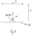
- the teeth 72, 84 are coordinated with one another in such a way that, when the upper side 82 of the clamping element 60 is in direct contact with the lower side 74 of the depression 70 of the fastening element 36, they produce a positive connection which - when the two surfaces 82, 74 are pressed against one another - prevents the clamping element 60 from being displaced relative to the fastening element 36 in the displacement direction S (cf. Fig.4 and 7 ).
- the teeth 96, 98 of the toothings 72, 84 are designed in such a way that they allow the clamping element 60 to move back against the spring 62 and thus against the vertical V when a force is exerted on the clamping element 60 in the displacement direction S, which runs horizontally, relative to the fastening element 36.
- the teeth 96, 98 have, for example, an angle ⁇ with respect to the normal n of the surfaces 74, 82 in the range 50° ⁇ ⁇ ⁇ 60°.
- the toothings 72, 84 can then slide particularly easily on one another if the surfaces 74, 82 are not pressed against one another, and the positive connection between the toothings 72, 84 is nevertheless very secure if the surfaces 74, 82 are pressed against one another (cf. Fig.8 ).
- the eccentricity of the clamping lever 58 is caused by the fact that the first contact surface 100 is closer to the opening as a tangent than the second contact surface 102. 104 for the bearing pin 56 (cf. Fig.3 ).
- the curve 106 represents a ramp between these two distances.
- the distance between the second contact surface 102 and the opening 104 is dimensioned such that when the second contact surface 102 is in contact, the guide disk 64 is pressed directly onto the underside 88 of the clamping element 60 and the surfaces 74, 82 are thereby pressed against one another, whereby a positive connection is established between the toothings 72, 84 (cf. Fig. 7a ).
- the distance between the first contact surface 100 and the opening 104 is again dimensioned such that when the first contact surface 100 is in contact, the guide disk 64 is not pressed directly onto the underside 88 of the clamping element 60. However, the spiral spring 62 presses the surfaces 74, 82 against one another, which also creates a positive connection between the teeth 72, 84 (see. Fig. 7b ).
- the recess 44 of the anchor element 32 which rests against the recess 70 of the fastening element 36, forms an abutment with the drive 48 of the pin 50 to the clamping lever 58.
- a positive connection therefore always exists between the toothings 72, 84: Either the two toothings 72, 84 are pressed together by the clamping lever 58, so that the positive connection is created, or the two toothings 72, 84 are pressed together by the spiral spring 62, so that the positive connection is created. In the first case of pressing, however, it is a fixed positive connection and in the second case of pressing it is a releasable positive connection.
- the spiral spring 62 creates such a preload that even if the clamping element 60 is displaced relative to the fastening element 36, a positive connection is always established. As a result, a user who displaces the clamping element 60 relative to the fastening element 36 feels a ratcheted sliding, which is caused by a successive engagement and release of the positive connection between the teeth 72, 84 is effected under the pretension of the spiral spring 62.
- the clamping lever 58 By overcoming the curve 106, the clamping lever 58 is released from the Fig. 7a shown fixed position to the one in Fig. 7b shown position.
- the second contact surface 102 and the first contact surface 100 each form safety devices so that the clamping lever 58 will not rotate about the bearing pin 56 without active pivoting by a user. There are therefore locks for the respective position of the clamping lever 58.
- the fastening element 36 is a plastic injection-molded part, as are the clamping element 60 and the tensioning lever 58.
- the anchor element 32, the pin 50, the spiral spring 62 and the guide disk 64 are made of metal.
- jaws 110 are arranged in the angles 108 between the horizontally extending section 42 and the fastening section 34 (see. Fig.3 ).
- This guide could, for example, consist of a grip around the anchor element 32 similar to the jaws 110.
- the shape of the depression 44 could also be designed such that it slides against the depression 70 of the fastening element 36 over a certain section, so that the anti-rotation protection is achieved in this way.
- the fastening element 36 has locking elements 112 (cf. Fig.3 ) which engage with corresponding locking elements 114 of the support frame 12, which are part of the connecting means 26 (cf. Fig.2 ), whereby the wall bracket 14 can be fixed to the support frame.
- the support frame 12 is provided with the two wall brackets 14, whereby the locking elements 112 are clipped into the locking elements 114.
- the support frame 12 is placed at the place in the room where it is to be set up and the feet 22 are telescoped to the required length.
- the feet 22 are then screwed to the floor 24, but not fully tightened yet, whereby appropriate holes and, if necessary, dowels must be made in the floor 24.
- the two wall brackets are then adjusted so that the spirit level 30 indicates the exact leveling of the support frame 12 in both the vertical and horizontal directions.
- the locking sliding between the teeth 72, 84 allows a particularly sensitive adjustment of the wall brackets 14.
- the clamping levers 58 are moved to the Fig. 7a shown position, whereby the positive connection between the teeth 72, 84 is fixed and thus the position of the fastening element 36 to the anchor element 32 is fixed and secured.
- the screw connections of the feet 22 are fixed to the floor and then the elements 18, 20 of the sanitary equipment, a pre-wall (not shown) or the sanitary equipment (not shown) itself can be arranged on the support frame 12.
- a supporting structure or a wall 116 which has two wall sections 118, 120 which form a right angle between them. This is therefore a wall corner 122.
- the anchor element 32 can nevertheless be displaced relative to the fastening element 36 in the horizontal displacement direction S, an optimal adjustment of the positioning of the support frame 12 and the sanitary fitting arranged thereon (not shown) in relation to the wall corner 122 can be achieved.
- the installation of the wall bracket 14 is basically the same as in the first preferred application according to the Fig. 1 to 8 .
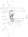
- the pivot angle ⁇ is additionally set in advance and then, when both the pivot angle ⁇ and the displacement between the anchor elements 32 relative to the respective fastening elements 36 have been carried out, the tensioning element 40 is locked so that the anchor elements 32 are locked relative to the respective fastening elements 36.
- the pivoting ability ⁇ is to be locked, for example if only a wall bracket is to be used, then this could be This can be done by providing a toothing (not shown) on the depression 70 and at the same time providing an opposing toothing on the lower outside of the depression 44. If at least one of the depressions 44, 70 is conical and the other depression 70, 44 is, for example, parallel conical (not shown), then these two toothings can be brought into engagement at least in some areas by the clamping with the clamping element 40, which would lock the pivotability ⁇ .
- the depression 70 could also be smooth and the lower outer surface of the depression 44 could be a conical polygon. Then locking could be ensured at least for some angular orientations ⁇ (depending on the number of surfaces of the polygon).
- Subsequent building or supporting structure monitoring can then also be carried out, whereby subsequent changes to the building or supporting structure can be easily detected.
- An acceleration sensor can also be used in this context.
- means for monitoring the air in the room can be arranged on the support frame 12, the means for monitoring the air in the room preferably having at least one of the elements temperature sensor, humidity sensor, spore sensor, dust sensor, smoke sensor and sensor for analyzing the presence of certain chemical substances.
- This means that further monitoring of the created pre-wall installation can be carried out with the help of the support frame 12. For example, it can be checked whether moisture collects behind the pre-wall installation over time or whether mold forms. Then it would be possible to react quickly to remedy the situation.
- the system 10 is designed to emit a signal when at least one state variable from the field of alignment of the support frame 12 and properties of the room air changes critically, with the signal preferably being emitted electrically or electronically, in particular wired or wirelessly. This allows continuous monitoring of the created pre-wall installation for critical states and/or building and supporting structure monitoring in principle.
- the adjustment of the wall bracket for fastening a sanitary fitting is significantly improved with the present invention.
- the adjustment of the wall bracket is quick and uncomplicated and can be done without tools, without the precision of the adjustment suffering.
- the support frame according to the invention which has means for checking the horizontal and/or vertical alignment of the support frame
- the mounting of the support frame on a supporting structure can be carried out very quickly and easily.
- the pre-wall installation created in this way can be further improved if subsequent building or supporting structure monitoring is made possible by the means for checking the horizontal and/or vertical alignment, an acceleration sensor and/or means for monitoring the room air, which would also be arranged on the support frame.
Landscapes
- Health & Medical Sciences (AREA)
- Life Sciences & Earth Sciences (AREA)
- Engineering & Computer Science (AREA)
- Hydrology & Water Resources (AREA)
- Public Health (AREA)
- Water Supply & Treatment (AREA)
- Connection Of Plates (AREA)
- Residential Or Office Buildings (AREA)
Applications Claiming Priority (1)
| Application Number | Priority Date | Filing Date | Title |
|---|---|---|---|
| DE102023105119.9A DE102023105119A1 (de) | 2023-03-01 | 2023-03-01 | Wandhalterung zur Befestigung eines Sanitärausstattungsgegenstandes und System zur Befestigung eines Sanitärausstattungsgegenstandes |
Publications (2)
| Publication Number | Publication Date |
|---|---|
| EP4424939A2 true EP4424939A2 (fr) | 2024-09-04 |
| EP4424939A3 EP4424939A3 (fr) | 2024-12-18 |
Family
ID=90097744
Family Applications (1)
| Application Number | Title | Priority Date | Filing Date |
|---|---|---|---|
| EP24160022.0A Pending EP4424939A3 (fr) | 2023-03-01 | 2024-02-27 | Support mural pour fixer un cadre de montage d'un accessoire sanitaire et système de fixation d'un accessoire sanitaire |
Country Status (2)
| Country | Link |
|---|---|
| EP (1) | EP4424939A3 (fr) |
| DE (1) | DE102023105119A1 (fr) |
Citations (2)
| Publication number | Priority date | Publication date | Assignee | Title |
|---|---|---|---|---|
| DE102017130596A1 (de) | 2017-12-19 | 2019-06-19 | Sanitärtechnik Eisenberg GmbH | Rohrbelüfter und System zur Rohrbelüftung |
| EP4039897A1 (fr) | 2021-02-04 | 2022-08-10 | Geberit International AG | Support mural |
Family Cites Families (9)
| Publication number | Priority date | Publication date | Assignee | Title |
|---|---|---|---|---|
| EP1936045A1 (fr) * | 2006-12-19 | 2008-06-25 | Geberit Technik Ag | Dispositif d'installation pour un dispositif sanitaire et dispositif sanitaire avec un tel dispositif d'installation |
| DE202009002494U1 (de) * | 2009-02-26 | 2009-06-10 | Sanitärtechnik Eisenberg GmbH | Vorrichtung zur Verbindung von Profilschienen mit Objekten |
| EP2450492B1 (fr) * | 2010-11-09 | 2019-03-27 | Geberit International AG | Système de fixation d'un article sanitaire |
| DE102012110779B4 (de) * | 2012-11-09 | 2016-05-12 | Mepa-Pauli Und Menden Gmbh | Wannenanker |
| DE102015002784A1 (de) * | 2015-04-30 | 2016-11-03 | Grohe Ag | Sanitärhalterung, eine Sanitäranordnung und Verfahren zum Betrieb einer Sanitäranordnung |
| GB2551157A (en) * | 2016-06-08 | 2017-12-13 | Mechline Developments Ltd | Basin |
| DE102017110760A1 (de) * | 2017-05-17 | 2018-11-22 | Viega Technology Gmbh & Co. Kg | Befestigungsset zum Befestigen eines Montagegestells für Sanitärobjekt und Verwendung eines solchen Befestigungssets |
| CZ34202U1 (cs) * | 2020-06-17 | 2020-07-07 | Alca Plast, S.R.O. | Fixační opěrka pro kotvení nosných rámů sanitárních zařízení ke zdivu |
| AT523381B1 (de) * | 2020-06-24 | 2021-08-15 | Mhs Montagesysteme Fuer Heizung Und Sanitaer Gmbh | Leitungsmodul zum zu- und/oder abführen von versorgungsmedien an eine oder von einer geschossebene eines gebäudes |
-
2023
- 2023-03-01 DE DE102023105119.9A patent/DE102023105119A1/de active Pending
-
2024
- 2024-02-27 EP EP24160022.0A patent/EP4424939A3/fr active Pending
Patent Citations (2)
| Publication number | Priority date | Publication date | Assignee | Title |
|---|---|---|---|---|
| DE102017130596A1 (de) | 2017-12-19 | 2019-06-19 | Sanitärtechnik Eisenberg GmbH | Rohrbelüfter und System zur Rohrbelüftung |
| EP4039897A1 (fr) | 2021-02-04 | 2022-08-10 | Geberit International AG | Support mural |
Also Published As
| Publication number | Publication date |
|---|---|
| DE102023105119A1 (de) | 2024-09-05 |
| EP4424939A3 (fr) | 2024-12-18 |
Similar Documents
| Publication | Publication Date | Title |
|---|---|---|
| EP2873792B1 (fr) | Penture | |
| DE2706437C2 (de) | Vorrichtung zum Verbinden von wenigstens zwei, vorzugsweise aus Hohlprofilen gebildeten Rahmenteilen mittels eines Verbindungselementes | |
| EP2876222A1 (fr) | Dispositif de fixation encastré pour un WC suspendu | |
| EP3789550A1 (fr) | Dispositif d'encliquetage | |
| EP4067594A1 (fr) | Ferrure de jonction | |
| EP3401452B1 (fr) | Dispositif de montage pour un objet sanitaire | |
| EP4424939A2 (fr) | Support mural pour fixer un cadre de montage d'un accessoire sanitaire et système de fixation d'un accessoire sanitaire | |
| DE102023105118A1 (de) | Wandhalterung zur Befestigung eines Sanitärausstattungsgegenstandes und System zur Befestigung eines Sanitärausstattungsgegenstandes | |
| DE102023105120A1 (de) | Tragrahmen zur Befestigung eines Sanitärausstattungsgegenstandes und System zur Befestigung eines Sanitärausstattungsgegenstandes | |
| DE8202424U1 (de) | Treppe | |
| DE102018010372A1 (de) | Rostverriegelungsvorrichtung für einen Rost einer Entwässerungsrinne sowie höhenverstellbare Entwässerungsrinne | |
| EP2107173A2 (fr) | Drain à fente avec réglage de hauteur | |
| EP2594718B1 (fr) | Dispositif de fixation d'un corps de construction dans une ouverture de bâtiment | |
| EP3502373B1 (fr) | Coffrage pour un escalier préfabriqué | |
| EP4474658B1 (fr) | Ensemble d'ancrage mural | |
| EP2754810A2 (fr) | Paroi de séparation | |
| EP2818600B1 (fr) | Bouche d'égout comprenant un couvercle ajustable | |
| EP3816366B1 (fr) | Construction d'appui pourvu de plusieurs éléments profilés allongés | |
| EP3085849B1 (fr) | Système de montage | |
| EP3964655A1 (fr) | Élément de fixation | |
| DE102006029431B3 (de) | Treppe mit höhenverstellbaren Stufen | |
| DE202017002529U1 (de) | Montageeinrichtung für einen Sanitärgegenstand | |
| EP3379012A1 (fr) | Dispositif de guidage réglable pour un élément coulissant | |
| DE202022105791U1 (de) | Keilbeschlag | |
| EP4595174A1 (fr) | Support plancher d'un système de support de câble |
Legal Events
| Date | Code | Title | Description |
|---|---|---|---|
| PUAI | Public reference made under article 153(3) epc to a published international application that has entered the european phase |
Free format text: ORIGINAL CODE: 0009012 |
|
| STAA | Information on the status of an ep patent application or granted ep patent |
Free format text: STATUS: THE APPLICATION HAS BEEN PUBLISHED |
|
| AK | Designated contracting states |
Kind code of ref document: A2 Designated state(s): AL AT BE BG CH CY CZ DE DK EE ES FI FR GB GR HR HU IE IS IT LI LT LU LV MC ME MK MT NL NO PL PT RO RS SE SI SK SM TR |
|
| PUAL | Search report despatched |
Free format text: ORIGINAL CODE: 0009013 |
|
| PUAF | Information related to the publication of a search report (a3 document) modified or deleted |
Free format text: ORIGINAL CODE: 0009199SEPU |
|
| PUAL | Search report despatched |
Free format text: ORIGINAL CODE: 0009013 |
|
| AK | Designated contracting states |
Kind code of ref document: A3 Designated state(s): AL AT BE BG CH CY CZ DE DK EE ES FI FR GB GR HR HU IE IS IT LI LT LU LV MC ME MK MT NL NO PL PT RO RS SE SI SK SM TR |
|
| RIC1 | Information provided on ipc code assigned before grant |
Ipc: E03D 11/14 20060101AFI20241023BHEP |
|
| D17D | Deferred search report published (deleted) | ||
| AK | Designated contracting states |
Kind code of ref document: A3 Designated state(s): AL AT BE BG CH CY CZ DE DK EE ES FI FR GB GR HR HU IE IS IT LI LT LU LV MC ME MK MT NL NO PL PT RO RS SE SI SK SM TR |
|
| RIC1 | Information provided on ipc code assigned before grant |
Ipc: E03D 11/14 20060101AFI20241113BHEP |
|
| STAA | Information on the status of an ep patent application or granted ep patent |
Free format text: STATUS: REQUEST FOR EXAMINATION WAS MADE |
|
| 17P | Request for examination filed |
Effective date: 20250523 |