EP4043661A1 - Beschattungsvorrichtung mit entwässerungskanal - Google Patents
Beschattungsvorrichtung mit entwässerungskanal Download PDFInfo
- Publication number
- EP4043661A1 EP4043661A1 EP22155888.5A EP22155888A EP4043661A1 EP 4043661 A1 EP4043661 A1 EP 4043661A1 EP 22155888 A EP22155888 A EP 22155888A EP 4043661 A1 EP4043661 A1 EP 4043661A1
- Authority
- EP
- European Patent Office
- Prior art keywords
- cover
- drainage channel
- shading device
- cloth
- shell
- Prior art date
- Legal status (The legal status is an assumption and is not a legal conclusion. Google has not performed a legal analysis and makes no representation as to the accuracy of the status listed.)
- Granted
Links
Images



Classifications
-
- E—FIXED CONSTRUCTIONS
- E04—BUILDING
- E04F—FINISHING WORK ON BUILDINGS, e.g. STAIRS, FLOORS
- E04F10/00—Sunshades, e.g. Florentine blinds or jalousies; Outside screens; Awnings or baldachins
- E04F10/02—Sunshades, e.g. Florentine blinds or jalousies; Outside screens; Awnings or baldachins of flexible canopy materials, e.g. canvas ; Baldachins
- E04F10/06—Sunshades, e.g. Florentine blinds or jalousies; Outside screens; Awnings or baldachins of flexible canopy materials, e.g. canvas ; Baldachins comprising a roller-blind with means for holding the end away from a building
-
- E—FIXED CONSTRUCTIONS
- E04—BUILDING
- E04F—FINISHING WORK ON BUILDINGS, e.g. STAIRS, FLOORS
- E04F10/00—Sunshades, e.g. Florentine blinds or jalousies; Outside screens; Awnings or baldachins
- E04F10/02—Sunshades, e.g. Florentine blinds or jalousies; Outside screens; Awnings or baldachins of flexible canopy materials, e.g. canvas ; Baldachins
- E04F10/06—Sunshades, e.g. Florentine blinds or jalousies; Outside screens; Awnings or baldachins of flexible canopy materials, e.g. canvas ; Baldachins comprising a roller-blind with means for holding the end away from a building
- E04F10/0666—Accessories
- E04F10/0677—Accessories acting as centre bearing
-
- E—FIXED CONSTRUCTIONS
- E04—BUILDING
- E04F—FINISHING WORK ON BUILDINGS, e.g. STAIRS, FLOORS
- E04F10/00—Sunshades, e.g. Florentine blinds or jalousies; Outside screens; Awnings or baldachins
- E04F10/02—Sunshades, e.g. Florentine blinds or jalousies; Outside screens; Awnings or baldachins of flexible canopy materials, e.g. canvas ; Baldachins
- E04F10/06—Sunshades, e.g. Florentine blinds or jalousies; Outside screens; Awnings or baldachins of flexible canopy materials, e.g. canvas ; Baldachins comprising a roller-blind with means for holding the end away from a building
- E04F10/0685—Covers or housings for the rolled-up blind
-
- E—FIXED CONSTRUCTIONS
- E04—BUILDING
- E04F—FINISHING WORK ON BUILDINGS, e.g. STAIRS, FLOORS
- E04F10/00—Sunshades, e.g. Florentine blinds or jalousies; Outside screens; Awnings or baldachins
- E04F10/02—Sunshades, e.g. Florentine blinds or jalousies; Outside screens; Awnings or baldachins of flexible canopy materials, e.g. canvas ; Baldachins
- E04F10/06—Sunshades, e.g. Florentine blinds or jalousies; Outside screens; Awnings or baldachins of flexible canopy materials, e.g. canvas ; Baldachins comprising a roller-blind with means for holding the end away from a building
- E04F10/0692—Front bars
- E04F10/0696—Front bars with means to attach an auxiliary screen
Definitions
- the invention relates to a shading device according to the preamble of claim 1.
- a shading device of the type mentioned can be, for example, an awning, in particular an articulated arm awning or a so-called vertical awning, or a conservatory shading.
- an awning is assumed as an example, but the invention is not limited thereto.
- a fabric in an awning, can be adjusted between a stretched position, in which it shades a desired area, and a retracted position, wound up on a fabric shaft.
- the roller tube runs essentially horizontally and can be attached to a substructure, for example a building wall or a stand structure, via holders on a supporting structure, for example in the form of brackets or a connection profile or guide rails.
- the roller tube of the awning is accommodated in a box-like housing, but there are also awning designs in which the roller tube is exposed.
- an awning is shown in which a shell-shaped cover is arranged below the fabric shaft, which surrounds the fabric shaft and the fabric wound thereon. The purpose of the cover is to protect the roller tube and the rolled-up fabric from unwanted external influences.
- the cover is arranged essentially concentrically to the roller tube and has a concave shape in the direction of the roller tube. If the cloth is wound up on the cloth shaft in a wet state, for example after it has rained, the water contained in the cloth drips onto the section of the cover arranged under the cloth shaft and collects in it.
- the awning In order to be able to drain water that is in the housing, the awning must be in accordance with the EP 0 792 978 A1 provided that in a lower area of the cover and in particular in the area of the lower apex of the cover, a channel-shaped drainage channel is arranged, which extends in the longitudinal direction of the roller tube.
- Water that is in the rolled-up fabric runs on the inside of the cover to its lower area and enters the channel-shaped drainage channel, in which the water is drained in the longitudinal direction of the awning and thus in the longitudinal direction of the fabric shaft, i.e. parallel to it and is discharged at a suitable position.
- the water drips also not down out of the awning, but it is diverted and disposed of in the desired way.
- the object of the invention is to provide a shading device of the type mentioned, in which a sliding coating can be attached in a simplified manner to the side of the cover facing the roller tube.
- this object is achieved by a shading device having the features of claim 1 . It is provided that on the side of the cover facing the roller tube, a sliding coating is arranged at least in sections, which ends in the drainage channel or completely lines it. According to the invention, the basic idea is to use the drainage channel for precise positioning and attachment of the sliding coating to use. This facilitates the assembly of the sliding coating.
- the sliding coating is formed by an inherently stable, prefabricated sliding shell, in particular made of plastic, which is attached to the shell-shaped cover.
- “Inherently stable” is intended to mean that the sliding shell retains its basic shape and structure when supported at certain points under its own weight and does not collapse, as would be the case with a foil or fabric that is slack under pressure.
- the sliding shell is designed as an injection molded part or as an extruded profile bar.
- the sliding coating is formed by an inherently stable, prefabricated sliding shell, this can preferably be placed on the cover and fastened to it in an exchangeable manner.
- the sliding shell can be attached to the cover by latching and/or clamping and/or screwing and/or gluing.
- a latching element or an undercut can be formed on or in the drainage channel.
- the sliding coating is formed by a layer of material or a film applied to the shell-shaped cover.
- the applied layer of material can be, for example, a sprayed or painted layer of paint or lacquer.
- a prefabricated film can be provided on the cover hang up and attach to this and in particular to glue.
- the material of the sliding lining or the sliding shell has a lower coefficient of friction than the material of the cover.
- the sliding coating or the sliding shell is preferably made of a plastic which, in combination with the material of the cloth, has good sliding properties and low friction.
- a corresponding plastic should be able to be injected or preferably extruded in order to be able to form the sliding shell as an extruded strand.
- Additives can be mixed into the plastic to reduce static on the cloth when it is being wound or unwound.
- An awning usually has a projection rod which is connected to the edge of the cloth facing away from the cloth shaft.
- the sliding coating or the sliding shell is only arranged on a section of the cover facing the dropout bar. A section of the cover facing away from the projection bar is then free of sliding lining.
- the drainage channel is an integral part of the cover.
- the cover is preferably made of plastic or metal, with the drainage channel being integrated into the cross-sectional shape of the cover and thus being a monolithic part of the cover.
- the drainage channel can be open on the side facing the roller tube, i.e. it can be designed as a so-called gravity channel. This ensures that unwanted foreign bodies, such as leaves that have gotten into the awning together with the fabric, cannot clog the drainage channel because the water can flow around the foreign bodies.
- the drainage channel can be formed by bending the cover.
- the cover with an integrated drainage channel is preferably designed as an extruded profile.
- the cover and the drainage channel are produced as separate components.
- the drainage channel can then be attached to the cover, for example welded, glued or latched, or arranged at a distance from the cover below it.
- the drainage channel is preferably arranged on the underside of the cover facing away from the roller tube, it being possible for the drainage channel to be arranged either in direct contact with the cover or as an integrated part of it or at a distance from the cover.
- the water emerging from the rolled-up cloth then flows on the inside of the cover to its lower area, it being possible for at least one through-opening to be formed in the cover above the drainage channel which the water flows from above into the drainage canal.
- the passage opening can be formed by a bore, but it is preferably provided that the passage opening is a slot running in the longitudinal direction of the drainage channel.
- slots can be provided, which are arranged at a distance one behind the other in the longitudinal direction of the roller tube or the drainage channel.
- a relatively long slot which can preferably extend over at least 60% of the axial length of the cover, in particular over at least 80% of the axial length of the cover and possibly also over the entire axial length of the cover.
- the cover consists of a single, one-piece component.
- the cover can be composed of at least two shell parts that engage with each other. Each shell part extends in the longitudinal direction of the cover, so that the cross section of the cover is formed by the shell parts.
- the shell parts can be locked together or welded or glued together.
- the shell parts are preferably each formed as a partial shell and can be arranged such that their area of engagement, ie the region of mutual engagement, is located at the lower vertex of the cross-section of the cover formed by the shell parts.
- the drainage channel is then preferably formed in the engagement area of the shell parts.
- the sliding coating can be arranged on both shell parts or only on one of the shell parts.
- the roller tube and the cover can be housed in a box-like housing which is attached to a support structure.
- the support structure can be a building wall or a support frame.
- the cover is preferably arranged in the housing and mounted on the housing.
- the drainage channel can extend over only a portion of the axial length and preferably over the entire axial length of the cover. In particular, it is provided that the drainage channel extends over at least 80% of the axial length of the cover.
- At least one of the axial ends of the drainage channel is arranged in an axial end area of the housing.
- the water flowing in the drainage channel can be discharged from the drainage channel.
- a diversion device is arranged on at least one of the axial ends of the drainage channel.
- the drainage device can be a continuing drainage channel in the form of a channel or a hose.
- the drainage channel can have any desired cross-section; it is preferably provided that the drainage channel has a V-shaped or a rectangular or a trapezoidal cross-section. It should Drainage channel have at least a cross-sectional area of 20mm 2 and in particular at least 40mm 2 .
- the shape and size of the cross-section of the drainage channel depend on the size of the wound cloth and thus on the maximum amount of water to be drained off.
- the drainage channel preferably consists of a single channel extending in the longitudinal direction of the roller tube.
- two channels arranged next to one another can also be provided, which are preferably connected to one another via a passage at points spaced apart in the longitudinal direction of the drainage channel, in order to enable equalization of the liquid level.
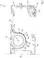
- FIG. 1 shows a schematic representation of a cross section through a shading device 10 according to the invention in the form of an awning.
- the shading device 10 has a box-like housing 13, which is perpendicular to the plane of 1 extends.
- a roller tube 12 that extends in the longitudinal direction of the housing 13 and rotates around a perpendicular to the plane of the drawing in 1 running axis of rotation D is rotatable.
- a cloth 11 is wound onto the cloth shaft 12 and is in engagement at its front end with a drop-out rod 14 which can be extended, ie moved away from the housing 13 or drawn towards the housing 13, as indicated by the double file A.
- the shading device 10 can be attached by means of the housing 13 to a support device 15, not shown in detail, which can be, for example, a building wall.
- a shell-shaped cover 16 is arranged, which runs at a distance below the roller tube 12 and is also perpendicular to the plane of the drawing 1 extends.
- the cover 16 is designed as a half-shell which is arranged essentially concentrically to the axis of rotation D and surrounds the roller tube 12 on its underside at a distance.
- the cloth roll that is thus located on the cloth shaft 12 is so thick that it rests against the inner wall of the cover 16 and is supported by it.
- the drainage channel 19 is formed by molding the cover 16 and is thus an integral, monolithic part of the cover 16.
- the drainage channel 19 is arranged on the underside of the cover 16 facing away from the roller tube 12 and is open in the direction of the cover 16, so that water from above, ie can flow into the drainage channel 19 from the side of the cover 16 facing the roller tube 12 .
- the water can flow along the inner wall of the cover 16 facing the cloth shaft 12 and enter the drainage channel 19 designed as an open channel.
- the water flows in the longitudinal direction, i.e. parallel to the axis of rotation D of the roller tube 12, preferably to an axial end region of the drainage channel 19 and/or the roller tube 12 and/or the housing 13, where it can be drained off by means of a drainage device 23, which can only be drawn through is indicated by an arrow, are discharged from the shading device 10.
- the sliding coating 24 is formed by a prefabricated, inherently stable sliding shell 24a, which is attached to the shell-shaped cover 16 and locked with it. At its lower end facing the drainage channel 19, the sliding coating 24 engages in the drainage channel 19, but without lining it completely, and engages behind a projection 17a formed on the cover 16. At its opposite end, facing away from the drainage channel 19, the sliding coating 24 encompasses an upper projection 17b of the cover 16, so that the sliding coating 24 is held on the cover 16 in a form-fitting manner.
- a downwardly extendable valance (not shown) is arranged in the projection bar 14 and is mounted on a valance shaft 25 can be wound up and unwound from this.
- a valance cover 26 is arranged below the valance corrugation 25 and has a valance drainage channel 27 in its lower apex region. The construction of the valance cover 26 and the valance drainage channel 27 can correspond to the construction of the cover 16 or the drainage channel 19 .
- the sliding coating 24 is not applied over the entire surface of the cover 16, but only in accordance with figure 1 right portion 16a of the cover 16, which faces the dropout bar 14.
- One of the dropout rod 14 facing away, according to 1 left section 16b of the cover 16 is free of sliding linings.
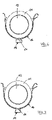
- the design according to 2 differs from the design according to 1 characterized in that now also in the section 16b of the cover 16, which faces away from the extension bar 14, a sliding coating 24 of the structure mentioned is arranged.
- the sliding linings 24 grab with their lower, ends facing the drainage channel 19 each into the drainage channel 19, but without lining it completely.
- the drainage channel 19 has a rectangular cross section which is open towards the top in the direction of the roller tube 12 .
- the cover 16 and the drainage channel 19 are designed as a one-piece, monolithic component.
- 4 shows an alternative embodiment, according to which the cover 16 and the drainage channel 19 are designed as separate components and then joined together.
- the drainage channel 19 can be welded or latched or glued to the cover 16 .
- figure 5 12 shows a further alternative, in which the cross-section of the cover 16 is composed of two shell parts 18a and 18b which are connected or engaged with one another in a connection area 20.
- FIG. The connection area 20 is arranged on or in the lower apex of the cover 16 and in the connection area 20 the drainage channel 19 is formed by a downwardly protruding bead of at least one of the shell parts 18a.
- the drainage channel 19 has a V-shaped cross-section and one shell part 18b carries the sliding coating 24 of the structure mentioned on its side facing the roller tube 12 .
- the cross section of the drainage channel 19 is increased, but it still has a substantially rectangular cross-section and is connected via an upper passage opening 21 to the inside of the cover 16 facing the roller tube 12 .
- the design of the drainage channel 19 according to 7 differs in that the drainage channel 19 now has a trapezoidal cross-section, with the larger trapezoidal side being arranged on the lower side of the cross-section facing away from the roller tube 12 .
- the drainage channel 19 consists of two spaced apart channels 19a which run parallel to one another and in the longitudinal direction of the roller tube 12.
- the two channels 19a can be connected to one another via openings in one or more areas spaced apart from one another in the longitudinal direction of the roller tube 12 .
- the design according to 9 differs from the design according to 8 in that a support area 28 is arranged between the two grooves 19a, which can come into contact with the outer surface of the cloth 11 wound up on the cloth shaft 12 and supports it accordingly.
Landscapes
- Engineering & Computer Science (AREA)
- Architecture (AREA)
- Civil Engineering (AREA)
- Structural Engineering (AREA)
- Building Awnings And Sunshades (AREA)
Abstract
Description
- Die Erfindung betrifft eine Beschattungsvorrichtung gemäß dem Oberbegriff des Anspruchs 1.
- Bei einer Beschattungsvorrichtung der genannten Art kann es sich beispielsweise um eine Markise, insbesondere eine Gelenkarm-Markise oder eine sogenannte Vertikal-Markise, oder um eine Wintergarten-Beschattung handeln. Im Folgenden wird beispielhaft von einer Markise ausgegangen, jedoch ist die Erfindung darauf nicht beschränkt.
- Bei einer Markise kann ein Tuch zwischen einer aufgespannten Position, in der es einen gewünschten Bereich abschattet, und einer eingezogenen, auf einer Tuchwelle aufgewickelten Position verstellt werden. Die Tuchwelle verläuft im Wesentlichen horizontal und kann über Halter an einer Tragkonstruktion beispielsweise in Form von Bügeln oder eines Anschlussprofils oder Führungsschienen an einer Unterkonstruktion, beispielsweise einer Gebäudewand oder einer Ständerkonstruktion angebracht sein.
- In vielen Fällen ist die Tuchwelle der Markise in einem kastenartigen Gehäuse aufgenommen, jedoch gibt es auch Markisenkonstruktionen, bei denen die Tuchwelle frei liegt. In der
EP 0 792 978 A1 ist eine Markise gezeigt, bei der unterhalb der Tuchwelle eine schalenförmige Abdeckung angeordnet ist, die die Tuchwelle und das darauf aufgewickelte Tuch umgibt. Die Abdeckung dient dem Zweck, die Tuchwelle und das aufgewickelte Tuch vor ungewollten äußeren Einflüssen zu schützen. - Die Abdeckung ist im Wesentlichen konzentrisch zur Tuchwelle angeordnet und in Richtung der Tuchwelle konkav geformt. Wenn das Tuch beispielsweise nach einem Regen in nassem Zustand auf der Tuchwelle aufgewickelt wird, tropft das im Tuch enthaltene Wasser auf den unter der Tuchwelle angeordneten Abschnitt der Abdeckung und sammelt sich in dieser. Um Wasser, das sich im Gehäuse befindet, ableiten zu können, ist bei der Markise gemäß der
EP 0 792 978 A1 vorgesehen, dass in einem unteren Bereich der Abdeckung und insbesondere im Bereich des unteren Scheitelpunktes der Abdeckung ein rinnenförmiger Entwässerungskanal angeordnet ist, der sich in Längsrichtung der Tuchwelle erstreckt. - Wasser, das sich in dem aufgewickelten Tuch befindet, läuft auf der Innenseite der Abdeckung zu deren unteren Bereich und tritt dort in den rinnenförmigen Entwässerungskanal ein, in dem das Wasser in Längsrichtung der Markise und somit in Längsrichtung der Tuchwelle, d.h. parallel dazu abgeleitet wird und an geeigneter Position abgeführt wird. Auf diese Weise ist es einerseits vermieden, dass sich das Wasser in dem Tuch staut und zu einer Verunreinigung oder Beschädigung des Tuches führt, andererseits tropft das Wasser auch nicht nach unten aus der Markise heraus, sondern es wird in gewünschter Weise abgeleitet und entsorgt.
- Auch aus der
EP 3 392 425 Bl ist es bekannt, die Abdeckung so auszubilden, dass die Tuchwelle zumindest mit dem vollständig aufgewickelten Tuch auf der der Tuchwelle zugewandten Seite der Abdeckung anliegt und durch die Abdeckung abgestützt wird. Auf diese Weise soll eine übermäßige Durchbiegung der Tuchwelle in Folge der Last des aufgewickelten Tuches vermieden werden. Zumindest in der letzten Phase der Einzugsbewegung des Tuches gleitet das Tuch über die Oberfläche der schalenförmigen Abdeckung. Um die Reibung zwischen dem Tuch und der Oberfläche der schalenförmigen Abdeckung zu minimieren, können gemäß derEP 3 392 425 B1 reibungsmindernde Einlagen oder Auflagen an der Abstützung vorgesehen sein. Die Anbringung von reibungsmindernden Einlagen oder Auflagen ist hinsichtlich der Montage ungünstig und zeitaufwändig und somit teuer. - Der Erfindung liegt die Aufgabe zugrunde, eine Beschattungsvorrichtung der genannten Art zu schaffen, bei der ein Gleitbelag auf der der Tuchwelle zugewandten Seite der Abdeckung in vereinfachter Weise angebracht werden kann.
- Diese Aufgabe wird erfindungsgemäß durch eine Beschattungsvorrichtung mit den Merkmalen des Anspruchs 1 gelöst. Dabei ist vorgesehen, dass auf der der Tuchwelle zugewandten Seite der Abdeckung zumindest abschnittsweise ein Gleitbelag angeordnet ist, der in dem Entwässerungskanal endet oder diesen vollständig auskleidet. Erfindungsgemäß wird von der Grundüberlegung ausgegangen, den Entwässerungskanal zur genauen Positionierung und Anbringung des Gleitbelages mit heranzuziehen. Dies erleichtert die Montage des Gleitbelags.
- In bevorzugter Ausgestaltung der Erfindung ist vorgesehen, dass der Gleitbelag von einer eigenstabilen, vorgefertigten Gleitschale insbesondere aus Kunststoff gebildet ist, die an der schalenförmigen Abdeckung angebracht ist. "Eigenstabil" soll bedeuten, dass die Gleitschale bei punktueller Abstützung unter Eigengewicht ihre grundsätzliche Form und Struktur beibehält und nicht in sich zusammenfällt, wie es bei einer druckschlaffen Folie oder einem Gewebe der Fall wäre. In einer möglichen Ausgestaltung der Erfindung kann vorgesehen sein, dass die Gleitschale als Spritzgussteil oder als extrudierter Profilstab ausgestaltet ist.
- Wenn der Gleitbelag von einer eigenstabilen, vorgefertigten Gleitschale gebildet ist, kann diese vorzugsweise in auswechselbarer Weise auf die Abdeckung aufgesetzt und an dieser befestigt werden. Die Befestigung der Gleitschale an der Abdeckung kann durch eine Verrastung und/oder eine Klemmung und/oder eine Verschraubung und/oder eine Verklebung erfolgen. Um die Gleitschale zu verrasten, kann an oder in dem Entwässerungskanal ein Rastelement oder eine Hinterschneidung ausgebildet sein.
- In alternativer Ausgestaltung der Erfindung kann vorgesehen sein, dass der Gleitbelag von einer auf die schalenförmige Abdeckung aufgebrachten Materialschicht oder einer Folie gebildet ist. Bei der aufgebrachten Materialschicht kann es sich beispielsweise um eine aufgespritzte oder aufgestrichene Farb- oder Lackschicht handeln. Alternativ kann vorgesehen sein, eine vorgefertigte Folie auf die Abdeckung aufzulegen und an dieser zu befestigen und insbesondere zu verkleben.
- Das Material des Gleitbelags oder der Gleitschale weist einen geringeren Reibungskoeffizienten als das Material der Abdeckung auf.
- Der Gleitbelag oder die Gleitschale besteht vorzugsweise aus einem Kunststoff, der in Kombination mit dem Material des Tuches gute Gleiteigenschaften und nur geringe Reibung aufweist. Ein entsprechender Kunststoff sollte spritzbar oder vorzugsweise extrudierbar sein, um die Gleitschale als extrudierten Strang ausbilden zu können. In den Kunststoff können Zusatzstoffe eingemischt werden, um die statische Aufladung des Tuches beim Aufwickeln oder Abwickeln zu verringern.
- Eine Markise weist üblicherweise eine Ausfallstange auf, die an der der Tuchwelle abgewandten Kante des Tuches mit diesem verbunden ist. In bevorzugter Ausgestaltung der Erfindung ist vorgesehen, dass der Gleitbelag oder die Gleitschale nur auf einem der Ausfallstange zugewandten Abschnitt der Abdeckung angeordnet ist. Ein der Ausfallstange abgewandter Abschnitt der Abdeckung ist dann gleitbelagfrei.
- In einer möglichen Ausgestaltung der Erfindung ist vorgesehen, dass der Entwässerungskanal einstückiger Bestandteil der Abdeckung ist. Die Abdeckung besteht vorzugsweise aus Kunststoff oder Metall, wobei der Entwässerungskanal in die Querschnittsform der Abdeckung integriert und somit monolithischer Bestandteil der Abdeckung sein kann.
- Der Entwässerungskanal kann auf seiner der Tuchwelle zugewandten Seite offen sein, d.h. als sogenanntes Freispiegelgerinne ausgebildet sein. Auf diese Weise ist sichergestellt, dass auch unerwünschte Fremdkörper beispielsweise Blätter, die zusammen mit dem Tuch in die Markise gelangt sind, den Entwässerungskanal nicht verstopfen können, da das Wasser die Fremdkörper umströmen kann.
- Wenn die Abdeckung aus Metall besteht, kann der Entwässerungskanal durch einen Biegevorgang an der Abdeckung ausgebildet werden.
- Wenn die Abdeckung aus Kunststoff besteht, ist die Abdeckung mit integriertem Entwässerungskanal vorzugsweise als Stranggussprofil ausgebildet.
- In einer alternativen Ausgestaltung der Erfindung kann vorgesehen sein, dass die Abdeckung und der Entwässerungskanal als separate Bauteile hergestellt werden. Der Entwässerungskanal kann dann an der Abdeckung angebracht, beispielsweise verschweißt, verklebt oder verrastet sein oder in Abstand zu der Abdeckung unterhalb von dieser angeordnet sein.
- Vorzugsweise ist der Entwässerungskanal auf der der Tuchwelle abgewandten Unterseite der Abdeckung angeordnet, wobei der Entwässerungskanal entweder in direkter Anlage mit der Abdeckung oder als integrierter Bestandteil von dieser oder mit Abstand zur Abdeckung angeordnet sein kann. Das aus dem aufgerollten Tuch austretende Wasser strömt dann auf der Innenseite der Abdeckung zu deren unterem Bereich, wobei in der Abdeckung oberhalb des Entwässerungskanals zumindest eine Durchlassöffnung ausgebildet sein kann, durch die das Wasser von oben in den Entwässerungskanal entströmt. Die Durchlassöffnung kann von einer Bohrung gebildet sein, vorzugsweise ist jedoch vorgesehen, dass die Durchlassöffnung einen in Längsrichtung des Entwässerungskanals verlaufender Schlitz ist.
- Es können mehrere Schlitze vorgesehen sein, die in Längsrichtung der Tuchwelle bzw. des Entwässerungskanals auf Abstand hintereinander angeordnet sind. Alternativ ist es jedoch auch möglich, einen relativ langen Schlitz vorzusehen, der sich vorzugsweise über zumindest 60% der axialen Länge der Abdeckung, insbesondere über zumindest 80% der axialen Länge der Abdeckung und gegebenenfalls auch über die gesamte axiale Länge der Abdeckung erstrecken kann.
- In einer möglichen Ausgestaltung der Erfindung kann vorgesehen sein, dass die Abdeckung aus einem einzigen, einstückigen Bauteil besteht. Alternativ kann die Abdeckung aus zumindest zwei Schalenteilen zusammengesetzt sein, die miteinander in Eingriff stehen. Jedes Schalenteil erstreckt sich in Längsrichtung der Abdeckung, so dass der Querschnitt der Abdeckung von den Schalenteilen gebildet ist. Die Schalenteile können miteinander verrastet oder auch miteinander verschweißt oder verklebt sein.
- Die Schalenteile sind vorzugsweise jeweils als Teil-Schale ausgebildet und können so angeordnet sein, dass ihr Eingriffsbereich, d.h. der Bereich des gegenseitigen Eingriffs, im unteren Scheitelpunkt des Querschnitts der durch die Schalenteile gebildeten Abdeckung angeordnet ist. Vorzugsweise ist dann der Entwässerungskanal im Eingriffsbereich der Schalenteile ausgebildet. Der Gleitbelag kann an beiden Schalenteilen oder auch nur an einem der Schalenteile angeordnet sein.
- Die Tuchwelle und die Abdeckung können in einem kastenartigen Gehäuse aufgenommen sein, das an einer Tragkonstruktion angebracht ist. Bei der Tragkonstruktion kann es sich um eine Gebäudewand oder auch um einen Tragrahmen handeln.
- Vorzugsweise ist die Abdeckung in diesem Fall in dem Gehäuse angeordnet und an dem Gehäuse gelagert.
- Der Entwässerungskanal kann sich über nur einen Anteil der axialen Länge und vorzugsweise über die gesamte axiale Länge der Abdeckung erstrecken. Insbesondere ist vorgesehen, dass der Entwässerungskanal sich über zumindest 80% der axialen Länge der Abdeckung erstreckt.
- In Weiterbildung der Erfindung kann vorgesehen sein, dass zumindest eines der axialen Enden des Entwässerungskanals in einem axialen Endbereich des Gehäuses angeordnet ist. In diesem axialen Endbereich des Gehäuses kann das in dem Entwässerungskanal strömende Wasser aus dem Entwässerungskanal abgeführt werden. Zu diesem Zweck kann vorgesehen sein, dass an zumindest einem der axialen Enden des Entwässerungskanals eine Ableitvorrichtung angeordnet ist. Bei der Ableitvorrichtung kann es sich um einen weiterführenden Ableitkanal in Form einer Rinne oder eines Schlauches handeln.
- Der Entwässerungskanal kann jeden beliebigen Querschnitt aufweisen, vorzugsweise ist vorgesehen, dass der Entwässerungskanal einen V-förmigen oder einen rechteckigen oder einen trapezförmigen Querschnitt aufweist. Dabei sollte der Entwässerungskanal mindestens eine Querschnittsfläche von 20mm2 und insbesondere von zumindest 40mm2 aufweisen.
- Die Form und die Größe des Querschnitts des Entwässerungskanals sind von der Größe des aufgewickelten Tuches und somit von der maximalen Menge des abzuleitenden Wassers abhängig.
- Vorzugsweise besteht der Entwässerungskanal aus einer einzigen sich in Längsrichtung der Tuchwelle erstreckenden Rinne. Alternativ können jedoch auch zwei nebeneinander angeordnete Rinnen vorgesehen sein, die vorzugsweise an in Längsrichtung des Entwässerungskanals beabstandeten Stellen jeweils über einen Durchlass miteinander verbunden sind, um einen Ausgleich des Flüssigkeitsspiegels zu ermöglichen.
- Weitere Einzelheiten und Merkmale der Erfindung sind aus der folgenden Beschreibung von Ausführungsbeispielen unter Bezugnahme auf die Zeichnungen ersichtlich. Es zeigen:
- Fig. 1
- einen Querschnitt durch eine erfindungsgemäße Beschattungsvorrichtung,
- Fig. 2
- eine erste alternative Ausgestaltung der Abdeckung,
- Fig. 3
- eine zweite alternative Ausgestaltung der Abdeckung,
- Fig. 4
- eine dritte alternative Ausgestaltung der Abdeckung,
- Fig. 5
- eine vierte alternative Ausgestaltung der Abdeckung,
- Fig. 6
- eine fünfte alternative Ausgestaltung der Abdeckung,
- Fig. 7
- eine sechste alternative Ausgestaltung der Abdeckung,
- Fig. 8
- eine siebte alternative Ausgestaltung der Abdeckung und
- Fig. 9
- eine achte alternative Ausgestaltung der Abdeckung.
-
Fig. 1 zeigt in schematischer Darstellung einen Querschnitt durch eine erfindungsgemäße Beschattungsvorrichtung 10 in Form einer Markise. Die Beschattungsvorrichtung 10 weist ein kastenartiges Gehäuse 13 auf, das sich senkrecht zur Zeichenebene vonFig. 1 erstreckt. In dem Gehäuse 13 ist eine sich in Längsrichtung des Gehäuses 13 erstreckende Tuchwelle 12 angeordnet, die um eine senkrecht zur Zeichenebene inFig. 1 verlaufende Drehachse D drehbar ist. Auf der Tuchwelle 12 ist ein Tuch 11 aufgewickelt, das an seinem vorderen Ende mit einer Ausfallstange 14 in Eingriff steht, die ausgefahren, d.h. vom Gehäuse 13 wegbewegt oder zum Gehäuse 13 hingezogen werden kann, wie es durch den Doppelfeil A angedeutet ist. - Wenn die Ausfallstange 14 vom Gehäuse 13 wegbewegt wird, d.h. nach rechts in
Fig. 1 , wird das Tuch 11 von der Tuchwelle 12 abgewickelt und aufgespannt. - Wenn die Ausfallstange 14 eingezogen und zum Gehäuse 13 hinbewegt wird, d.h. nach links in
Fig. 1 , wird das Tuch 11 auf die Tuchwelle 12 aufgewickelt. - Die Beschattungsvorrichtung 10 kann mittels des Gehäuses 13 an einer nicht näher dargestellten Tragvorrichtung 15 angebracht werden, bei der es sich beispielsweise um eine Gebäudewand handeln kann.
- In dem Gehäuse 13 ist eine schalenförmige Abdeckung 16 angeordnet, die mit Abstand unterhalb der Tuchwelle 12 verläuft und sich ebenfalls senkrecht zur Zeichenebene in
Fig. 1 erstreckt. Die Abdeckung 16 ist als Halbschale ausgebildet, die im Wesentlichen konzentrisch zur Drehachse D angeordnet ist und die Tuchwelle 12 auf deren Unterseite mit Abstand umgreift. - Wenn das Tuch 11 weitestgehend oder vollständig auf die Tuchwelle 12 aufgewickelt ist, ist die dadurch auf der Tuchwelle 12 befindlichen Tuchrolle so dick, dass sie an der Innenwandung der Abdeckung 16 anliegt und von dieser abgestützt wird.
- Im tiefsten Bereich, d.h. im unteren Scheitelpunkt der Abdeckung 16 ist ein rinnenförmiger Entwässerungskanal 19 mit einem V-förmigen Querschnitt angeordnet. Der Entwässerungskanal 19 ist durch Formung der Abdeckung 16 gebildet und somit ein einstückiger, monolithischer Bestandteil der Abdeckung 16.
- Der Entwässerungskanal 19 ist auf der der Tuchwelle 12 abgewandten Unterseite der Abdeckung 16 angeordnet und in Richtung der Abdeckung 16 offen, so dass Wasser von oben, d.h. von der der Tuchwelle 12 zugewandten Seite der Abdeckung 16 in den Entwässerungskanal 19 einströmen kann.
- Wenn das Tuch 11 in nassem Zustand aufgewickelt wird oder wenn in sonstiger Weise von oben Wasser in das Gehäuse 13 eintritt, kann das Wasser an der der Tuchwelle 12 zugewandten Innenwandung der Abdeckung 16 entlang strömen und in den als Freispiegelgerinne ausgebildete Entwässerungskanal 19 eintreten. In dem Entwässerungskanal 19 strömt das Wasser in Längsrichtung, d.h. parallel zur Drehachse D der Tuchwelle 12 bis vorzugsweise zu einem axialen Endbereich des Entwässerungskanals 19 und/oder der Tuchwelle 12 und/oder des Gehäuses 13 und kann dort mittels einer Ableitvorrichtung 23, die nur durch einen Pfeil angedeutet ist, aus der Beschattungsvorrichtung 10 abgeführt werden.
- Auf der inneren, der Tuchwelle 12 zugewandten Seite der Abdeckung 16 ist ein Gleitbelag 24 insbesondere aus Kunststoff angeordnet. Der Gleitbelag 24 ist von einer vorgefertigten, eigenstabilen Gleitschale 24a gebildet, die an der schalenförmigen Abdeckung 16 angebracht und mit dieser verrastet ist. An seinem unteren, dem Entwässerungskanal 19 zugewandten Ende greift der Gleitbelag 24 in den Entwässerungskanal 19 ein, ohne diesen jedoch vollständig auszukleiden, und hintergreift einen an der Abdeckung 16 ausgebildeten Vorsprung 17a. An seinem entgegengesetzten, dem Entwässerungskanal 19 abgewandten Ende umgreift der Gleitbelag 24 einen oberen Vorsprung 17b der Abdeckung 16, so dass der Gleitbelag 24 formschlüssig an der Abdeckung 16 gehalten ist.
- In der Ausfallstange 14 ist ein nach unten ausfahrbarer Volant (nicht dargestellt) angeordnet, der auf einer Volant-Welle 25 aufwickelbar und von dieser abwickelbar ist. Unterhalb der Volant-Welle 25 ist eine Volant-Abdeckung 26 angeordnet, die in ihrem unteren Scheitelbereich einen Volant-Entwässerungskanal 27 aufweist. Der konstruktive Aufbau der Volant-Abdeckung 26 und des Volant-Entwässerungskanals 27 kann dem konstruktiven Aufbau der Abdeckung 16 bzw. des Entwässerungskanals 19 entsprechen.
- Wie
Figur 1 zeigt, ist der Gleitbelag 24 nicht vollflächig auf die Abdeckung 16 aufgebracht, sondern nur in dem gemäßFigur 1 rechten Abschnitt 16a der Abdeckung 16 angeordnet, der der Ausfallstange 14 zugewandt ist. Ein der Ausfallstange 14 abgewandter, gemäßFig. 1 linker Abschnitt 16b der Abdeckung 16 ist gleitbelagfrei. - Wenn die Ausfallstange 14 ausgefahren und dadurch das Tuch 11 gespannt und aufgespannt wird, wird die Tuchwelle 12 mit dem darauf aufgewickeltem Tuch 11 gegen den der Ausfallstange 14 zugewandten Abschnitts 16a der Abdeckung 16 gespannt, so dass zwischen der Außenseite des aufgewickelten Tuches 11 und diesem Abschnitt 16a der Abdeckung 16 hohe Reibungskräfte auftreten würden, die durch den auf der Abdeckung 16 angeordneten Gleitbelag 24 gemindert werden.
- Die folgenden Figuren zeigen Abwandlungen des konstruktiven Aufbaus der Abdeckung 16 und/oder des Gleitbelags 24 und/oder des wellenförmigen Entwässerungskanals 19:
Die Ausgestaltung gemäßFig. 2 unterscheidet sich von der Ausgestaltung gemäßFig. 1 dadurch, dass nunmehr auch in dem Abschnitt 16b der Abdeckung 16, der der Ausfallstange 14 abgewandt ist, ein Gleitbelag 24 des genannten Aufbaus angeordnet ist. Die Gleitbeläge 24 greifen mit ihren unteren, dem Entwässerungskanal 19 zugewandten Enden jeweils in den Entwässerungskanal 19 ein, ohne diesen jedoch vollständig auszukleiden. Eine Ausgestaltung, bei der nur ein einzelner Gleitbelag 24 vorgesehen ist, der den Entwässerungskanal 19 vollständig auskleidet, ist inFig. 3 dargestellt. - Gemäß den
Fig. 2 und 3 weist der Entwässerungskanal 19 einen rechteckigen, nach oben in Richtung der Tuchwelle 12 offenen Querschnitt auf. - Gemäß den
Fig. 1 ,2 und 3 sind die Abdeckung 16 und der Entwässerungskanal 19 als einstückiges, monolithisches Bauteil ausgebildet.Fig. 4 zeigt eine alternative Ausgestaltung, wonach die Abdeckung 16 und der Entwässerungskanal 19 als separate Bauteile ausgebildet und anschließend zusammengefügt sind. Der Entwässerungskanal 19 kann mit der Abdeckung 16 verschweißt oder verrastet oder verklebt sein. -
Fig. 5 zeigt eine weitere Alternative, wobei der Querschnitt der Abdeckung 16 aus zwei Schalenteilen 18a und 18b zusammengesetzt ist, die in einem Verbindungsbereich 20 miteinander verbunden sind bzw. in Eingriff stehen. Der Verbindungsbereich 20 ist an oder in dem unteren Scheitelpunkt der Abdeckung 16 angeordnet und im Verbindungsbereich 20 ist der Entwässerungskanal 19 durch eine nach untern hervorstehende Sicke zumindest eines der Schalenteile 18a ausgebildet. Der Entwässerungskanal 19 weist einen V-förmigen Querschnitt auf und das eine Schalenteil 18b trägt auf seiner der Tuchwelle 12 zugewandten Seite den Gleitbelag 24 genannten Aufbaus. - Gemäß
Fig. 6 ist der Querschnitt des Entwässerungskanals 19 vergrößert, jedoch besitzt er weiterhin einen im Wesentlichen rechteckigen Querschnitt und steht über eine obere Durchlassöffnung 21 mit der der Tuchwelle 12 zugewandten Innenseite der Abdeckung 16 in Verbindung. - Die Ausgestaltung des Entwässerungskanals 19 gemäß
Fig. 7 unterscheidet sich dadurch, dass der Entwässerungskanal 19 nunmehr ein trapezförmigen Querschnitt besitzt, wobei die größere Trapez-Seite auf der unteren, der Tuchwelle 12 abgewandten Seite des Querschnitts angeordnet ist. - Gemäß
Fig. 8 besteht der Entwässerungskanal 19 aus zwei auf Abstand nebeneinander angeordneten Rinnen 19a, die parallel zueinander und in Längsrichtung der Tuchwelle 12 verlaufen. Die beiden Rinnen 19a können an einer oder mehreren in Längsrichtung der Tuchwelle 12 voneinander beabstandeten Bereichen über Durchlässe miteinander verbunden sein. - Die Ausgestaltung gemäß
Fig. 9 unterscheidet sich von der Ausgestaltung gemäßFig. 8 dadurch, dass zwischen den beiden Rinnen 19a ein Stützbereich 28 angeordnet ist, der mit der Außenoberfläche des auf der Tuchwelle 12 aufgewickelten Tuches 11 in Anlage kommen kann und dieses entsprechend abstützt.
Claims (14)
- Beschattungsvorrichtung (10) mit einem Tuch (11) und einer Tuchwelle (12), auf die das Tuch (11) aufwickelbar und von der es abwickelbar ist, wobei unterhalb der Tuchwelle (12) eine schalenförmige Abdeckung (16) angeordnet ist, die die Tuchwelle (12) und das darauf aufgewickelte Tuch (11) über einen Teilumfang abstützt, wobei in einem unteren Bereich der Abdeckung (16) ein rinnenförmiger Entwässerungskanal (19) angeordnet ist, der sich in Längsrichtung der Tuchwelle (12) erstreckt, dadurch gekennzeichnet, dass auf der der Tuchwelle (12) zugewandten Seite der Abdeckung (16) zumindest abschnittsweise ein Gleitbelag (24) angeordnet ist, der in dem Entwässerungskanal (19) endet oder diesen vollständig auskleidet.
- Beschattungsvorrichtung nach Anspruch 1, dadurch gekennzeichnet, dass der Gleitbelag (24) von einer eigenstabilen, vorgefertigten Gleitschale (24a) gebildet ist, die an der schalenförmigen Abdeckung (16) angebracht ist.
- Beschattungsvorrichtung nach Anspruch 2, dadurch gekennzeichnet, dass die Gleitschale (24a) mit der Abdeckung (16) verrastet ist.
- Beschattungsvorrichtung nach Anspruch 1, dadurch gekennzeichnet, dass der Gleitbelag (24) von einer auf die schalenförmige Abdeckung (16) aufgebrachten Materialschicht oder einer Folie gebildet ist.
- Beschattungsvorrichtung nach einem der Ansprüche 1 bis 4, dadurch gekennzeichnet, dass die Beschattungsvorrichtung (10) eine Ausfallstange (14) aufweist, die mit dem Tuch (11) verbunden ist, und dass der Gleitbelag (24) nur auf einem der Ausfallstange (24) zugewandten Abschnitt (16a) der Abdeckung (16) angeordnet ist.
- Beschattungsvorrichtung nach einem Ansprüche 1 bis 5, dadurch gekennzeichnet, dass der Entwässerungskanal (19) einstückiger Bestandteil der Abdeckung (16) ist.
- Beschattungsvorrichtung nach einem der Ansprüche 1 bis 6, dadurch gekennzeichnet, dass der Entwässerungskanal (19) auf der der Tuchwelle (12) abgewandten Unterseite der Abdeckung (16) angeordnet ist und dass in der Abdeckung (16) oberhalb des Entwässerungskanals (19) eine Durchlassöffnung (21) ausgebildet ist.
- Beschattungsvorrichtung nach Anspruch 7, dadurch gekennzeichnet, dass die Durchlassöffnung (21) einen in Längsrichtung der Tuchwelle (12) verlaufender Schlitz (22) ist.
- Beschattungsvorrichtung nach einem der Ansprüche 1 bis 8, dadurch gekennzeichnet, dass die Abdeckung (16) aus zumindest zwei Schalenteilen (18a, 18b) zusammengesetzt ist, die miteinander in Eingriff stehen.
- Beschattungsvorrichtung nach Anspruch 9, dadurch gekennzeichnet, dass der Entwässerungskanal (19) in einem Verbindungsbereich (20) der Schalenteile (18a, 18b) ausgebildet ist.
- Beschaffungsvorrichtung nach einem der Ansprüche 1 bis 10, dadurch gekennzeichnet, dass die Tuchwelle (12) in einem kastenartigen Gehäuse (13) aufgenommen ist, das an einer Tragkonstruktion (15) angebracht ist, und dass die Abdeckung (16) in dem Gehäuse (13) angeordnet ist.
- Beschattungsvorrichtung nach einem der Ansprüche 1 bis 11, dadurch gekennzeichnet, dass der Entwässerungskanal (19) sich über zumindest 80% der axialen Länge der Abdeckung (16) erstreckt.
- Beschattungsvorrichtung nach einem der Ansprüche 1 bis 12, dadurch gekennzeichnet, dass an zumindest einem der axialen Enden des Entwässerungskanals (19) eine Ableitvorrichtung (23) angeordnet ist.
- Beschattungsvorrichtung nach einem der Ansprüche 1 bis 13, dadurch gekennzeichnet, dass der Entwässerungskanal (19) einen V-förmigen oder rechteckigen oder trapezförmigen Querschnitt (19a, 19b) aufweist.
Applications Claiming Priority (1)
| Application Number | Priority Date | Filing Date | Title |
|---|---|---|---|
| DE102021103137.0A DE102021103137A1 (de) | 2021-02-10 | 2021-02-10 | Beschattungsvorrichtung |
Publications (2)
| Publication Number | Publication Date |
|---|---|
| EP4043661A1 true EP4043661A1 (de) | 2022-08-17 |
| EP4043661B1 EP4043661B1 (de) | 2023-05-24 |
Family
ID=80445967
Family Applications (1)
| Application Number | Title | Priority Date | Filing Date |
|---|---|---|---|
| EP22155888.5A Active EP4043661B1 (de) | 2021-02-10 | 2022-02-09 | Beschattungsvorrichtung mit entwässerungskanal |
Country Status (2)
| Country | Link |
|---|---|
| EP (1) | EP4043661B1 (de) |
| DE (1) | DE102021103137A1 (de) |
Citations (3)
| Publication number | Priority date | Publication date | Assignee | Title |
|---|---|---|---|---|
| EP0792978A1 (de) | 1996-03-01 | 1997-09-03 | Schmitz-Werke GmbH & Co. | Markise, insbesondere Kassettenmarkise |
| DE102006059470A1 (de) * | 2006-03-13 | 2007-09-20 | "Weinor" Dieter Weiermann Gmbh & Co | Stützvorrichtung zum Abstützen eines Wickelballens, insbesondere eines Markisentuchballens |
| EP3392425A1 (de) * | 2017-04-21 | 2018-10-24 | Weinor GmbH & Co. KG | Horizontalträger mit senkrechtbeschattung und verstellbarer abstützung |
Family Cites Families (4)
| Publication number | Priority date | Publication date | Assignee | Title |
|---|---|---|---|---|
| DE19716829C2 (de) | 1997-04-22 | 2003-09-25 | Weiermann Dieter Weinor | Markise |
| DE20001537U1 (de) | 2000-01-31 | 2000-07-06 | Roedelbronn Gmbh | Hülsenmarkise |
| DE10150709C2 (de) | 2001-10-13 | 2003-12-11 | Erhardt Markisenbau Gmbh | Markise |
| DE102004022352B4 (de) | 2004-04-29 | 2013-07-11 | Giovanni Scaffidi | Markise |
-
2021
- 2021-02-10 DE DE102021103137.0A patent/DE102021103137A1/de not_active Withdrawn
-
2022
- 2022-02-09 EP EP22155888.5A patent/EP4043661B1/de active Active
Patent Citations (4)
| Publication number | Priority date | Publication date | Assignee | Title |
|---|---|---|---|---|
| EP0792978A1 (de) | 1996-03-01 | 1997-09-03 | Schmitz-Werke GmbH & Co. | Markise, insbesondere Kassettenmarkise |
| DE102006059470A1 (de) * | 2006-03-13 | 2007-09-20 | "Weinor" Dieter Weiermann Gmbh & Co | Stützvorrichtung zum Abstützen eines Wickelballens, insbesondere eines Markisentuchballens |
| EP3392425A1 (de) * | 2017-04-21 | 2018-10-24 | Weinor GmbH & Co. KG | Horizontalträger mit senkrechtbeschattung und verstellbarer abstützung |
| EP3392425B1 (de) | 2017-04-21 | 2020-01-08 | Weinor GmbH & Co. KG | Horizontalträger mit senkrechtbeschattung und verstellbarer abstützung |
Also Published As
| Publication number | Publication date |
|---|---|
| EP4043661B1 (de) | 2023-05-24 |
| DE102021103137A1 (de) | 2022-08-11 |
Similar Documents
| Publication | Publication Date | Title |
|---|---|---|
| EP0562245B1 (de) | Markise | |
| DE19717654C2 (de) | Markisenhalterung | |
| EP4043661B1 (de) | Beschattungsvorrichtung mit entwässerungskanal | |
| WO2021110426A1 (de) | Beschattungsvorrichtung | |
| DE4402964B4 (de) | Gelenkarmmarkise | |
| DE2027369A1 (de) | Montagevorrichtung fur aufrollbare Zelte oder Markisen | |
| DE2249265B2 (de) | Befestigung eines Modernisierungsfensters am in der Wand verbleibenden Stockrahmen des alten Fensters | |
| DE9305774U1 (de) | Fensterbank | |
| EP4382720B1 (de) | Schienenvorrichtung zum lagern einer elementschiene, die zum seitlichen führen eines sonnenschutzelements zum verhindern des eintretens von sonnenlicht in ein gebäude ausgelegt ist | |
| DE69822386T2 (de) | Leitersatz für Feuerwehrleitern | |
| CH655757A5 (en) | Awning | |
| EP1118731B1 (de) | Gelenkarm-Markise mit einer Abdeckung, insbesondere Kassetten-Markise | |
| DE29903324U1 (de) | Rahmen eines Fensters, einer Klappe oder einer Tür an Wohnwagen, Wohnmobilen oder sonstigen Fahrzeugen | |
| DE4015995C2 (de) | Sonnenschutz | |
| DE69000703T2 (de) | Vorrichtung, um ein sonnenschirmtuch unter spannung zu halten, insbesondere fuer eine veranda oder pergola. | |
| DE3110336A1 (de) | "markise" | |
| DE102004032725A1 (de) | Beschattungsvorrichtung | |
| DE2509071A1 (de) | Sonnendach | |
| EP0572772A1 (de) | Gelenkarm-Markise mit Einrichtungen zum Fixieren des Ausfallrohres | |
| DE20001537U1 (de) | Hülsenmarkise | |
| DE19531261C2 (de) | Wintergartenmarkise | |
| DE10300788B4 (de) | Beschattungsvorrichtung | |
| EP3486421B1 (de) | Senkrechtmarkise | |
| EP1380467B1 (de) | Markisenbefestigungsleiste für Fahrzeuge | |
| EP1127996A2 (de) | Struktur und automatischer Sperrmechanismus für Markisen |
Legal Events
| Date | Code | Title | Description |
|---|---|---|---|
| PUAI | Public reference made under article 153(3) epc to a published international application that has entered the european phase |
Free format text: ORIGINAL CODE: 0009012 |
|
| STAA | Information on the status of an ep patent application or granted ep patent |
Free format text: STATUS: THE APPLICATION HAS BEEN PUBLISHED |
|
| AK | Designated contracting states |
Kind code of ref document: A1 Designated state(s): AL AT BE BG CH CY CZ DE DK EE ES FI FR GB GR HR HU IE IS IT LI LT LU LV MC MK MT NL NO PL PT RO RS SE SI SK SM TR |
|
| STAA | Information on the status of an ep patent application or granted ep patent |
Free format text: STATUS: REQUEST FOR EXAMINATION WAS MADE |
|
| 17P | Request for examination filed |
Effective date: 20220906 |
|
| RBV | Designated contracting states (corrected) |
Designated state(s): AL AT BE BG CH CY CZ DE DK EE ES FI FR GB GR HR HU IE IS IT LI LT LU LV MC MK MT NL NO PL PT RO RS SE SI SK SM TR |
|
| GRAP | Despatch of communication of intention to grant a patent |
Free format text: ORIGINAL CODE: EPIDOSNIGR1 |
|
| STAA | Information on the status of an ep patent application or granted ep patent |
Free format text: STATUS: GRANT OF PATENT IS INTENDED |
|
| RIC1 | Information provided on ipc code assigned before grant |
Ipc: E04F 10/06 20060101AFI20221222BHEP |
|
| INTG | Intention to grant announced |
Effective date: 20230120 |
|
| GRAS | Grant fee paid |
Free format text: ORIGINAL CODE: EPIDOSNIGR3 |
|
| GRAA | (expected) grant |
Free format text: ORIGINAL CODE: 0009210 |
|
| STAA | Information on the status of an ep patent application or granted ep patent |
Free format text: STATUS: THE PATENT HAS BEEN GRANTED |
|
| AK | Designated contracting states |
Kind code of ref document: B1 Designated state(s): AL AT BE BG CH CY CZ DE DK EE ES FI FR GB GR HR HU IE IS IT LI LT LU LV MC MK MT NL NO PL PT RO RS SE SI SK SM TR |
|
| REG | Reference to a national code |
Ref country code: GB Ref legal event code: FG4D Free format text: NOT ENGLISH |
|
| REG | Reference to a national code |
Ref country code: CH Ref legal event code: EP |
|
| REG | Reference to a national code |
Ref country code: DE Ref legal event code: R096 Ref document number: 502022000014 Country of ref document: DE |
|
| REG | Reference to a national code |
Ref country code: AT Ref legal event code: REF Ref document number: 1569562 Country of ref document: AT Kind code of ref document: T Effective date: 20230615 |
|
| P01 | Opt-out of the competence of the unified patent court (upc) registered |
Effective date: 20230517 |
|
| REG | Reference to a national code |
Ref country code: IE Ref legal event code: FG4D Free format text: LANGUAGE OF EP DOCUMENT: GERMAN |
|
| REG | Reference to a national code |
Ref country code: NL Ref legal event code: FP |
|
| REG | Reference to a national code |
Ref country code: LT Ref legal event code: MG9D |
|
| PG25 | Lapsed in a contracting state [announced via postgrant information from national office to epo] |
Ref country code: SE Free format text: LAPSE BECAUSE OF FAILURE TO SUBMIT A TRANSLATION OF THE DESCRIPTION OR TO PAY THE FEE WITHIN THE PRESCRIBED TIME-LIMIT Effective date: 20230524 Ref country code: PT Free format text: LAPSE BECAUSE OF FAILURE TO SUBMIT A TRANSLATION OF THE DESCRIPTION OR TO PAY THE FEE WITHIN THE PRESCRIBED TIME-LIMIT Effective date: 20230925 Ref country code: NO Free format text: LAPSE BECAUSE OF FAILURE TO SUBMIT A TRANSLATION OF THE DESCRIPTION OR TO PAY THE FEE WITHIN THE PRESCRIBED TIME-LIMIT Effective date: 20230824 Ref country code: ES Free format text: LAPSE BECAUSE OF FAILURE TO SUBMIT A TRANSLATION OF THE DESCRIPTION OR TO PAY THE FEE WITHIN THE PRESCRIBED TIME-LIMIT Effective date: 20230524 |
|
| PG25 | Lapsed in a contracting state [announced via postgrant information from national office to epo] |
Ref country code: RS Free format text: LAPSE BECAUSE OF FAILURE TO SUBMIT A TRANSLATION OF THE DESCRIPTION OR TO PAY THE FEE WITHIN THE PRESCRIBED TIME-LIMIT Effective date: 20230524 Ref country code: PL Free format text: LAPSE BECAUSE OF FAILURE TO SUBMIT A TRANSLATION OF THE DESCRIPTION OR TO PAY THE FEE WITHIN THE PRESCRIBED TIME-LIMIT Effective date: 20230524 Ref country code: LV Free format text: LAPSE BECAUSE OF FAILURE TO SUBMIT A TRANSLATION OF THE DESCRIPTION OR TO PAY THE FEE WITHIN THE PRESCRIBED TIME-LIMIT Effective date: 20230524 Ref country code: LT Free format text: LAPSE BECAUSE OF FAILURE TO SUBMIT A TRANSLATION OF THE DESCRIPTION OR TO PAY THE FEE WITHIN THE PRESCRIBED TIME-LIMIT Effective date: 20230524 Ref country code: IS Free format text: LAPSE BECAUSE OF FAILURE TO SUBMIT A TRANSLATION OF THE DESCRIPTION OR TO PAY THE FEE WITHIN THE PRESCRIBED TIME-LIMIT Effective date: 20230924 Ref country code: HR Free format text: LAPSE BECAUSE OF FAILURE TO SUBMIT A TRANSLATION OF THE DESCRIPTION OR TO PAY THE FEE WITHIN THE PRESCRIBED TIME-LIMIT Effective date: 20230524 Ref country code: GR Free format text: LAPSE BECAUSE OF FAILURE TO SUBMIT A TRANSLATION OF THE DESCRIPTION OR TO PAY THE FEE WITHIN THE PRESCRIBED TIME-LIMIT Effective date: 20230825 |
|
| PG25 | Lapsed in a contracting state [announced via postgrant information from national office to epo] |
Ref country code: FI Free format text: LAPSE BECAUSE OF FAILURE TO SUBMIT A TRANSLATION OF THE DESCRIPTION OR TO PAY THE FEE WITHIN THE PRESCRIBED TIME-LIMIT Effective date: 20230524 |
|
| PG25 | Lapsed in a contracting state [announced via postgrant information from national office to epo] |
Ref country code: SK Free format text: LAPSE BECAUSE OF FAILURE TO SUBMIT A TRANSLATION OF THE DESCRIPTION OR TO PAY THE FEE WITHIN THE PRESCRIBED TIME-LIMIT Effective date: 20230524 |
|
| PG25 | Lapsed in a contracting state [announced via postgrant information from national office to epo] |
Ref country code: SM Free format text: LAPSE BECAUSE OF FAILURE TO SUBMIT A TRANSLATION OF THE DESCRIPTION OR TO PAY THE FEE WITHIN THE PRESCRIBED TIME-LIMIT Effective date: 20230524 Ref country code: SK Free format text: LAPSE BECAUSE OF FAILURE TO SUBMIT A TRANSLATION OF THE DESCRIPTION OR TO PAY THE FEE WITHIN THE PRESCRIBED TIME-LIMIT Effective date: 20230524 Ref country code: RO Free format text: LAPSE BECAUSE OF FAILURE TO SUBMIT A TRANSLATION OF THE DESCRIPTION OR TO PAY THE FEE WITHIN THE PRESCRIBED TIME-LIMIT Effective date: 20230524 Ref country code: EE Free format text: LAPSE BECAUSE OF FAILURE TO SUBMIT A TRANSLATION OF THE DESCRIPTION OR TO PAY THE FEE WITHIN THE PRESCRIBED TIME-LIMIT Effective date: 20230524 Ref country code: DK Free format text: LAPSE BECAUSE OF FAILURE TO SUBMIT A TRANSLATION OF THE DESCRIPTION OR TO PAY THE FEE WITHIN THE PRESCRIBED TIME-LIMIT Effective date: 20230524 Ref country code: CZ Free format text: LAPSE BECAUSE OF FAILURE TO SUBMIT A TRANSLATION OF THE DESCRIPTION OR TO PAY THE FEE WITHIN THE PRESCRIBED TIME-LIMIT Effective date: 20230524 |
|
| REG | Reference to a national code |
Ref country code: DE Ref legal event code: R097 Ref document number: 502022000014 Country of ref document: DE |
|
| PLBE | No opposition filed within time limit |
Free format text: ORIGINAL CODE: 0009261 |
|
| STAA | Information on the status of an ep patent application or granted ep patent |
Free format text: STATUS: NO OPPOSITION FILED WITHIN TIME LIMIT |
|
| 26N | No opposition filed |
Effective date: 20240227 |
|
| PG25 | Lapsed in a contracting state [announced via postgrant information from national office to epo] |
Ref country code: SI Free format text: LAPSE BECAUSE OF FAILURE TO SUBMIT A TRANSLATION OF THE DESCRIPTION OR TO PAY THE FEE WITHIN THE PRESCRIBED TIME-LIMIT Effective date: 20230524 |
|
| PG25 | Lapsed in a contracting state [announced via postgrant information from national office to epo] |
Ref country code: SI Free format text: LAPSE BECAUSE OF FAILURE TO SUBMIT A TRANSLATION OF THE DESCRIPTION OR TO PAY THE FEE WITHIN THE PRESCRIBED TIME-LIMIT Effective date: 20230524 |
|
| PG25 | Lapsed in a contracting state [announced via postgrant information from national office to epo] |
Ref country code: MC Free format text: LAPSE BECAUSE OF FAILURE TO SUBMIT A TRANSLATION OF THE DESCRIPTION OR TO PAY THE FEE WITHIN THE PRESCRIBED TIME-LIMIT Effective date: 20230524 |
|
| PG25 | Lapsed in a contracting state [announced via postgrant information from national office to epo] |
Ref country code: LU Free format text: LAPSE BECAUSE OF NON-PAYMENT OF DUE FEES Effective date: 20240209 |
|
| PG25 | Lapsed in a contracting state [announced via postgrant information from national office to epo] |
Ref country code: LU Free format text: LAPSE BECAUSE OF NON-PAYMENT OF DUE FEES Effective date: 20240209 |
|
| PG25 | Lapsed in a contracting state [announced via postgrant information from national office to epo] |
Ref country code: BG Free format text: LAPSE BECAUSE OF FAILURE TO SUBMIT A TRANSLATION OF THE DESCRIPTION OR TO PAY THE FEE WITHIN THE PRESCRIBED TIME-LIMIT Effective date: 20230524 |
|
| PG25 | Lapsed in a contracting state [announced via postgrant information from national office to epo] |
Ref country code: BG Free format text: LAPSE BECAUSE OF FAILURE TO SUBMIT A TRANSLATION OF THE DESCRIPTION OR TO PAY THE FEE WITHIN THE PRESCRIBED TIME-LIMIT Effective date: 20230524 |
|
| PG25 | Lapsed in a contracting state [announced via postgrant information from national office to epo] |
Ref country code: IE Free format text: LAPSE BECAUSE OF NON-PAYMENT OF DUE FEES Effective date: 20240209 |
|
| PG25 | Lapsed in a contracting state [announced via postgrant information from national office to epo] |
Ref country code: IE Free format text: LAPSE BECAUSE OF NON-PAYMENT OF DUE FEES Effective date: 20240209 |
|
| PG25 | Lapsed in a contracting state [announced via postgrant information from national office to epo] |
Ref country code: CY Free format text: LAPSE BECAUSE OF FAILURE TO SUBMIT A TRANSLATION OF THE DESCRIPTION OR TO PAY THE FEE WITHIN THE PRESCRIBED TIME-LIMIT; INVALID AB INITIO Effective date: 20220209 |
|
| PG25 | Lapsed in a contracting state [announced via postgrant information from national office to epo] |
Ref country code: TR Free format text: LAPSE BECAUSE OF FAILURE TO SUBMIT A TRANSLATION OF THE DESCRIPTION OR TO PAY THE FEE WITHIN THE PRESCRIBED TIME-LIMIT Effective date: 20230524 |
|
| REG | Reference to a national code |
Ref country code: CH Ref legal event code: U11 Free format text: ST27 STATUS EVENT CODE: U-0-0-U10-U11 (AS PROVIDED BY THE NATIONAL OFFICE) Effective date: 20260301 |
|
| PGFP | Annual fee paid to national office [announced via postgrant information from national office to epo] |
Ref country code: NL Payment date: 20260218 Year of fee payment: 5 |
|
| PGFP | Annual fee paid to national office [announced via postgrant information from national office to epo] |
Ref country code: DE Payment date: 20260119 Year of fee payment: 5 |
|
| PGFP | Annual fee paid to national office [announced via postgrant information from national office to epo] |
Ref country code: AT Payment date: 20260301 Year of fee payment: 5 |
|
| PGFP | Annual fee paid to national office [announced via postgrant information from national office to epo] |
Ref country code: BE Payment date: 20260218 Year of fee payment: 5 Ref country code: IT Payment date: 20260227 Year of fee payment: 5 |
|
| PGFP | Annual fee paid to national office [announced via postgrant information from national office to epo] |
Ref country code: FR Payment date: 20260226 Year of fee payment: 5 |
|
| PGFP | Annual fee paid to national office [announced via postgrant information from national office to epo] |
Ref country code: CH Payment date: 20260301 Year of fee payment: 5 |