EP4043661A1 - Dispositif d'ombrage avec canal de drainage - Google Patents
Dispositif d'ombrage avec canal de drainage Download PDFInfo
- Publication number
- EP4043661A1 EP4043661A1 EP22155888.5A EP22155888A EP4043661A1 EP 4043661 A1 EP4043661 A1 EP 4043661A1 EP 22155888 A EP22155888 A EP 22155888A EP 4043661 A1 EP4043661 A1 EP 4043661A1
- Authority
- EP
- European Patent Office
- Prior art keywords
- cover
- drainage channel
- shading device
- cloth
- shell
- Prior art date
- Legal status (The legal status is an assumption and is not a legal conclusion. Google has not performed a legal analysis and makes no representation as to the accuracy of the status listed.)
- Granted
Links
Images


Classifications
-
- E—FIXED CONSTRUCTIONS
- E04—BUILDING
- E04F—FINISHING WORK ON BUILDINGS, e.g. STAIRS, FLOORS
- E04F10/00—Sunshades, e.g. Florentine blinds or jalousies; Outside screens; Awnings or baldachins
- E04F10/02—Sunshades, e.g. Florentine blinds or jalousies; Outside screens; Awnings or baldachins of flexible canopy materials, e.g. canvas ; Baldachins
- E04F10/06—Sunshades, e.g. Florentine blinds or jalousies; Outside screens; Awnings or baldachins of flexible canopy materials, e.g. canvas ; Baldachins comprising a roller-blind with means for holding the end away from a building
- E04F10/0666—Accessories
- E04F10/0677—Accessories acting as centre bearing
-
- E—FIXED CONSTRUCTIONS
- E04—BUILDING
- E04F—FINISHING WORK ON BUILDINGS, e.g. STAIRS, FLOORS
- E04F10/00—Sunshades, e.g. Florentine blinds or jalousies; Outside screens; Awnings or baldachins
- E04F10/02—Sunshades, e.g. Florentine blinds or jalousies; Outside screens; Awnings or baldachins of flexible canopy materials, e.g. canvas ; Baldachins
- E04F10/06—Sunshades, e.g. Florentine blinds or jalousies; Outside screens; Awnings or baldachins of flexible canopy materials, e.g. canvas ; Baldachins comprising a roller-blind with means for holding the end away from a building
- E04F10/0685—Covers or housings for the rolled-up blind
-
- E—FIXED CONSTRUCTIONS
- E04—BUILDING
- E04F—FINISHING WORK ON BUILDINGS, e.g. STAIRS, FLOORS
- E04F10/00—Sunshades, e.g. Florentine blinds or jalousies; Outside screens; Awnings or baldachins
- E04F10/02—Sunshades, e.g. Florentine blinds or jalousies; Outside screens; Awnings or baldachins of flexible canopy materials, e.g. canvas ; Baldachins
- E04F10/06—Sunshades, e.g. Florentine blinds or jalousies; Outside screens; Awnings or baldachins of flexible canopy materials, e.g. canvas ; Baldachins comprising a roller-blind with means for holding the end away from a building
- E04F10/0692—Front bars
- E04F10/0696—Front bars with means to attach an auxiliary screen
Definitions
- the invention relates to a shading device according to the preamble of claim 1.
- a shading device of the type mentioned can be, for example, an awning, in particular an articulated arm awning or a so-called vertical awning, or a conservatory shading.
- an awning is assumed as an example, but the invention is not limited thereto.
- a fabric in an awning, can be adjusted between a stretched position, in which it shades a desired area, and a retracted position, wound up on a fabric shaft.
- the roller tube runs essentially horizontally and can be attached to a substructure, for example a building wall or a stand structure, via holders on a supporting structure, for example in the form of brackets or a connection profile or guide rails.
- the roller tube of the awning is accommodated in a box-like housing, but there are also awning designs in which the roller tube is exposed.
- an awning is shown in which a shell-shaped cover is arranged below the fabric shaft, which surrounds the fabric shaft and the fabric wound thereon. The purpose of the cover is to protect the roller tube and the rolled-up fabric from unwanted external influences.
- the cover is arranged essentially concentrically to the roller tube and has a concave shape in the direction of the roller tube. If the cloth is wound up on the cloth shaft in a wet state, for example after it has rained, the water contained in the cloth drips onto the section of the cover arranged under the cloth shaft and collects in it.
- the awning In order to be able to drain water that is in the housing, the awning must be in accordance with the EP 0 792 978 A1 provided that in a lower area of the cover and in particular in the area of the lower apex of the cover, a channel-shaped drainage channel is arranged, which extends in the longitudinal direction of the roller tube.
- Water that is in the rolled-up fabric runs on the inside of the cover to its lower area and enters the channel-shaped drainage channel, in which the water is drained in the longitudinal direction of the awning and thus in the longitudinal direction of the fabric shaft, i.e. parallel to it and is discharged at a suitable position.
- the water drips also not down out of the awning, but it is diverted and disposed of in the desired way.
- the object of the invention is to provide a shading device of the type mentioned, in which a sliding coating can be attached in a simplified manner to the side of the cover facing the roller tube.
- this object is achieved by a shading device having the features of claim 1 . It is provided that on the side of the cover facing the roller tube, a sliding coating is arranged at least in sections, which ends in the drainage channel or completely lines it. According to the invention, the basic idea is to use the drainage channel for precise positioning and attachment of the sliding coating to use. This facilitates the assembly of the sliding coating.
- the sliding coating is formed by an inherently stable, prefabricated sliding shell, in particular made of plastic, which is attached to the shell-shaped cover.
- “Inherently stable” is intended to mean that the sliding shell retains its basic shape and structure when supported at certain points under its own weight and does not collapse, as would be the case with a foil or fabric that is slack under pressure.
- the sliding shell is designed as an injection molded part or as an extruded profile bar.
- the sliding coating is formed by an inherently stable, prefabricated sliding shell, this can preferably be placed on the cover and fastened to it in an exchangeable manner.
- the sliding shell can be attached to the cover by latching and/or clamping and/or screwing and/or gluing.
- a latching element or an undercut can be formed on or in the drainage channel.
- the sliding coating is formed by a layer of material or a film applied to the shell-shaped cover.
- the applied layer of material can be, for example, a sprayed or painted layer of paint or lacquer.
- a prefabricated film can be provided on the cover hang up and attach to this and in particular to glue.
- the material of the sliding lining or the sliding shell has a lower coefficient of friction than the material of the cover.
- the sliding coating or the sliding shell is preferably made of a plastic which, in combination with the material of the cloth, has good sliding properties and low friction.
- a corresponding plastic should be able to be injected or preferably extruded in order to be able to form the sliding shell as an extruded strand.
- Additives can be mixed into the plastic to reduce static on the cloth when it is being wound or unwound.
- An awning usually has a projection rod which is connected to the edge of the cloth facing away from the cloth shaft.
- the sliding coating or the sliding shell is only arranged on a section of the cover facing the dropout bar. A section of the cover facing away from the projection bar is then free of sliding lining.
- the drainage channel is an integral part of the cover.
- the cover is preferably made of plastic or metal, with the drainage channel being integrated into the cross-sectional shape of the cover and thus being a monolithic part of the cover.
- the drainage channel can be open on the side facing the roller tube, i.e. it can be designed as a so-called gravity channel. This ensures that unwanted foreign bodies, such as leaves that have gotten into the awning together with the fabric, cannot clog the drainage channel because the water can flow around the foreign bodies.
- the drainage channel can be formed by bending the cover.
- the cover with an integrated drainage channel is preferably designed as an extruded profile.
- the cover and the drainage channel are produced as separate components.
- the drainage channel can then be attached to the cover, for example welded, glued or latched, or arranged at a distance from the cover below it.
- the drainage channel is preferably arranged on the underside of the cover facing away from the roller tube, it being possible for the drainage channel to be arranged either in direct contact with the cover or as an integrated part of it or at a distance from the cover.
- the water emerging from the rolled-up cloth then flows on the inside of the cover to its lower area, it being possible for at least one through-opening to be formed in the cover above the drainage channel which the water flows from above into the drainage canal.
- the passage opening can be formed by a bore, but it is preferably provided that the passage opening is a slot running in the longitudinal direction of the drainage channel.
- slots can be provided, which are arranged at a distance one behind the other in the longitudinal direction of the roller tube or the drainage channel.
- a relatively long slot which can preferably extend over at least 60% of the axial length of the cover, in particular over at least 80% of the axial length of the cover and possibly also over the entire axial length of the cover.
- the cover consists of a single, one-piece component.
- the cover can be composed of at least two shell parts that engage with each other. Each shell part extends in the longitudinal direction of the cover, so that the cross section of the cover is formed by the shell parts.
- the shell parts can be locked together or welded or glued together.
- the shell parts are preferably each formed as a partial shell and can be arranged such that their area of engagement, ie the region of mutual engagement, is located at the lower vertex of the cross-section of the cover formed by the shell parts.
- the drainage channel is then preferably formed in the engagement area of the shell parts.
- the sliding coating can be arranged on both shell parts or only on one of the shell parts.
- the roller tube and the cover can be housed in a box-like housing which is attached to a support structure.
- the support structure can be a building wall or a support frame.
- the cover is preferably arranged in the housing and mounted on the housing.
- the drainage channel can extend over only a portion of the axial length and preferably over the entire axial length of the cover. In particular, it is provided that the drainage channel extends over at least 80% of the axial length of the cover.
- At least one of the axial ends of the drainage channel is arranged in an axial end area of the housing.
- the water flowing in the drainage channel can be discharged from the drainage channel.
- a diversion device is arranged on at least one of the axial ends of the drainage channel.
- the drainage device can be a continuing drainage channel in the form of a channel or a hose.
- the drainage channel can have any desired cross-section; it is preferably provided that the drainage channel has a V-shaped or a rectangular or a trapezoidal cross-section. It should Drainage channel have at least a cross-sectional area of 20mm 2 and in particular at least 40mm 2 .
- the shape and size of the cross-section of the drainage channel depend on the size of the wound cloth and thus on the maximum amount of water to be drained off.
- the drainage channel preferably consists of a single channel extending in the longitudinal direction of the roller tube.
- two channels arranged next to one another can also be provided, which are preferably connected to one another via a passage at points spaced apart in the longitudinal direction of the drainage channel, in order to enable equalization of the liquid level.
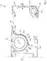
- FIG. 1 shows a schematic representation of a cross section through a shading device 10 according to the invention in the form of an awning.
- the shading device 10 has a box-like housing 13, which is perpendicular to the plane of 1 extends.
- a roller tube 12 that extends in the longitudinal direction of the housing 13 and rotates around a perpendicular to the plane of the drawing in 1 running axis of rotation D is rotatable.
- a cloth 11 is wound onto the cloth shaft 12 and is in engagement at its front end with a drop-out rod 14 which can be extended, ie moved away from the housing 13 or drawn towards the housing 13, as indicated by the double file A.
- the shading device 10 can be attached by means of the housing 13 to a support device 15, not shown in detail, which can be, for example, a building wall.
- a shell-shaped cover 16 is arranged, which runs at a distance below the roller tube 12 and is also perpendicular to the plane of the drawing 1 extends.
- the cover 16 is designed as a half-shell which is arranged essentially concentrically to the axis of rotation D and surrounds the roller tube 12 on its underside at a distance.
- the cloth roll that is thus located on the cloth shaft 12 is so thick that it rests against the inner wall of the cover 16 and is supported by it.
- the drainage channel 19 is formed by molding the cover 16 and is thus an integral, monolithic part of the cover 16.
- the drainage channel 19 is arranged on the underside of the cover 16 facing away from the roller tube 12 and is open in the direction of the cover 16, so that water from above, ie can flow into the drainage channel 19 from the side of the cover 16 facing the roller tube 12 .
- the water can flow along the inner wall of the cover 16 facing the cloth shaft 12 and enter the drainage channel 19 designed as an open channel.
- the water flows in the longitudinal direction, i.e. parallel to the axis of rotation D of the roller tube 12, preferably to an axial end region of the drainage channel 19 and/or the roller tube 12 and/or the housing 13, where it can be drained off by means of a drainage device 23, which can only be drawn through is indicated by an arrow, are discharged from the shading device 10.
- the sliding coating 24 is formed by a prefabricated, inherently stable sliding shell 24a, which is attached to the shell-shaped cover 16 and locked with it. At its lower end facing the drainage channel 19, the sliding coating 24 engages in the drainage channel 19, but without lining it completely, and engages behind a projection 17a formed on the cover 16. At its opposite end, facing away from the drainage channel 19, the sliding coating 24 encompasses an upper projection 17b of the cover 16, so that the sliding coating 24 is held on the cover 16 in a form-fitting manner.
- a downwardly extendable valance (not shown) is arranged in the projection bar 14 and is mounted on a valance shaft 25 can be wound up and unwound from this.
- a valance cover 26 is arranged below the valance corrugation 25 and has a valance drainage channel 27 in its lower apex region. The construction of the valance cover 26 and the valance drainage channel 27 can correspond to the construction of the cover 16 or the drainage channel 19 .
- the sliding coating 24 is not applied over the entire surface of the cover 16, but only in accordance with figure 1 right portion 16a of the cover 16, which faces the dropout bar 14.
- One of the dropout rod 14 facing away, according to 1 left section 16b of the cover 16 is free of sliding linings.
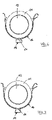
- the design according to 2 differs from the design according to 1 characterized in that now also in the section 16b of the cover 16, which faces away from the extension bar 14, a sliding coating 24 of the structure mentioned is arranged.
- the sliding linings 24 grab with their lower, ends facing the drainage channel 19 each into the drainage channel 19, but without lining it completely.
- the drainage channel 19 has a rectangular cross section which is open towards the top in the direction of the roller tube 12 .
- the cover 16 and the drainage channel 19 are designed as a one-piece, monolithic component.
- 4 shows an alternative embodiment, according to which the cover 16 and the drainage channel 19 are designed as separate components and then joined together.
- the drainage channel 19 can be welded or latched or glued to the cover 16 .
- figure 5 12 shows a further alternative, in which the cross-section of the cover 16 is composed of two shell parts 18a and 18b which are connected or engaged with one another in a connection area 20.
- FIG. The connection area 20 is arranged on or in the lower apex of the cover 16 and in the connection area 20 the drainage channel 19 is formed by a downwardly protruding bead of at least one of the shell parts 18a.
- the drainage channel 19 has a V-shaped cross-section and one shell part 18b carries the sliding coating 24 of the structure mentioned on its side facing the roller tube 12 .
- the cross section of the drainage channel 19 is increased, but it still has a substantially rectangular cross-section and is connected via an upper passage opening 21 to the inside of the cover 16 facing the roller tube 12 .
- the design of the drainage channel 19 according to 7 differs in that the drainage channel 19 now has a trapezoidal cross-section, with the larger trapezoidal side being arranged on the lower side of the cross-section facing away from the roller tube 12 .
- the drainage channel 19 consists of two spaced apart channels 19a which run parallel to one another and in the longitudinal direction of the roller tube 12.
- the two channels 19a can be connected to one another via openings in one or more areas spaced apart from one another in the longitudinal direction of the roller tube 12 .
- the design according to 9 differs from the design according to 8 in that a support area 28 is arranged between the two grooves 19a, which can come into contact with the outer surface of the cloth 11 wound up on the cloth shaft 12 and supports it accordingly.
Landscapes
- Engineering & Computer Science (AREA)
- Architecture (AREA)
- Civil Engineering (AREA)
- Structural Engineering (AREA)
- Building Awnings And Sunshades (AREA)
Applications Claiming Priority (1)
| Application Number | Priority Date | Filing Date | Title |
|---|---|---|---|
| DE102021103137.0A DE102021103137A1 (de) | 2021-02-10 | 2021-02-10 | Beschattungsvorrichtung |
Publications (2)
| Publication Number | Publication Date |
|---|---|
| EP4043661A1 true EP4043661A1 (fr) | 2022-08-17 |
| EP4043661B1 EP4043661B1 (fr) | 2023-05-24 |
Family
ID=80445967
Family Applications (1)
| Application Number | Title | Priority Date | Filing Date |
|---|---|---|---|
| EP22155888.5A Active EP4043661B1 (fr) | 2021-02-10 | 2022-02-09 | Dispositif d'ombrage avec canal de drainage |
Country Status (2)
| Country | Link |
|---|---|
| EP (1) | EP4043661B1 (fr) |
| DE (1) | DE102021103137A1 (fr) |
Citations (3)
| Publication number | Priority date | Publication date | Assignee | Title |
|---|---|---|---|---|
| EP0792978A1 (fr) | 1996-03-01 | 1997-09-03 | Schmitz-Werke GmbH & Co. | Marquise, notamment marquise à caisson |
| DE102006059470A1 (de) * | 2006-03-13 | 2007-09-20 | "Weinor" Dieter Weiermann Gmbh & Co | Stützvorrichtung zum Abstützen eines Wickelballens, insbesondere eines Markisentuchballens |
| EP3392425A1 (fr) * | 2017-04-21 | 2018-10-24 | Weinor GmbH & Co. KG | Support horizontal comprenant un ombrage vertical et support réglable |
Family Cites Families (4)
| Publication number | Priority date | Publication date | Assignee | Title |
|---|---|---|---|---|
| DE19716829C2 (de) | 1997-04-22 | 2003-09-25 | Weiermann Dieter Weinor | Markise |
| DE20001537U1 (de) | 2000-01-31 | 2000-07-06 | Roedelbronn Gmbh | Hülsenmarkise |
| DE10150709C2 (de) | 2001-10-13 | 2003-12-11 | Erhardt Markisenbau Gmbh | Markise |
| DE102004022352B4 (de) | 2004-04-29 | 2013-07-11 | Giovanni Scaffidi | Markise |
-
2021
- 2021-02-10 DE DE102021103137.0A patent/DE102021103137A1/de not_active Withdrawn
-
2022
- 2022-02-09 EP EP22155888.5A patent/EP4043661B1/fr active Active
Patent Citations (4)
| Publication number | Priority date | Publication date | Assignee | Title |
|---|---|---|---|---|
| EP0792978A1 (fr) | 1996-03-01 | 1997-09-03 | Schmitz-Werke GmbH & Co. | Marquise, notamment marquise à caisson |
| DE102006059470A1 (de) * | 2006-03-13 | 2007-09-20 | "Weinor" Dieter Weiermann Gmbh & Co | Stützvorrichtung zum Abstützen eines Wickelballens, insbesondere eines Markisentuchballens |
| EP3392425A1 (fr) * | 2017-04-21 | 2018-10-24 | Weinor GmbH & Co. KG | Support horizontal comprenant un ombrage vertical et support réglable |
| EP3392425B1 (fr) | 2017-04-21 | 2020-01-08 | Weinor GmbH & Co. KG | Support horizontal comprenant un ombrage vertical et support réglable |
Also Published As
| Publication number | Publication date |
|---|---|
| EP4043661B1 (fr) | 2023-05-24 |
| DE102021103137A1 (de) | 2022-08-11 |
Similar Documents
| Publication | Publication Date | Title |
|---|---|---|
| EP0562245B1 (fr) | Marquise | |
| DE19717654C2 (de) | Markisenhalterung | |
| EP4043661B1 (fr) | Dispositif d'ombrage avec canal de drainage | |
| WO2021110426A1 (fr) | Dispositif d'ombrage | |
| DE4402964B4 (de) | Gelenkarmmarkise | |
| DE2027369A1 (de) | Montagevorrichtung fur aufrollbare Zelte oder Markisen | |
| DE2249265B2 (de) | Befestigung eines Modernisierungsfensters am in der Wand verbleibenden Stockrahmen des alten Fensters | |
| DE9305774U1 (de) | Fensterbank | |
| EP4382720B1 (fr) | Dispositif de rail de support d'un rail d'élément destiné à guider latéralement un élément de protection solaire afin d'empêcher l'entrée de lumière solaire dans un bâtiment | |
| DE69822386T2 (de) | Leitersatz für Feuerwehrleitern | |
| CH655757A5 (en) | Awning | |
| EP1118731B1 (fr) | Marquise à bras articulés avec couvercle, notamment marquise à caisson | |
| DE29903324U1 (de) | Rahmen eines Fensters, einer Klappe oder einer Tür an Wohnwagen, Wohnmobilen oder sonstigen Fahrzeugen | |
| DE69000703T2 (de) | Vorrichtung, um ein sonnenschirmtuch unter spannung zu halten, insbesondere fuer eine veranda oder pergola. | |
| DE3110336A1 (de) | "markise" | |
| DE102004032725A1 (de) | Beschattungsvorrichtung | |
| DE4015995A1 (de) | Solarbeschattung | |
| DE2509071A1 (de) | Sonnendach | |
| EP0572772A1 (fr) | Store à bras articulés avec dispositif de fixation de la barre de charge | |
| DE20001537U1 (de) | Hülsenmarkise | |
| DE19531261C2 (de) | Wintergartenmarkise | |
| DE10300788B4 (de) | Beschattungsvorrichtung | |
| EP3486421B1 (fr) | Marquise verticale | |
| EP1380467B1 (fr) | Rail de fixation pour marquises de véhicules | |
| EP1127996A2 (fr) | Structure et mécanisme de verrouillage automatique pour marquises |
Legal Events
| Date | Code | Title | Description |
|---|---|---|---|
| PUAI | Public reference made under article 153(3) epc to a published international application that has entered the european phase |
Free format text: ORIGINAL CODE: 0009012 |
|
| STAA | Information on the status of an ep patent application or granted ep patent |
Free format text: STATUS: THE APPLICATION HAS BEEN PUBLISHED |
|
| AK | Designated contracting states |
Kind code of ref document: A1 Designated state(s): AL AT BE BG CH CY CZ DE DK EE ES FI FR GB GR HR HU IE IS IT LI LT LU LV MC MK MT NL NO PL PT RO RS SE SI SK SM TR |
|
| STAA | Information on the status of an ep patent application or granted ep patent |
Free format text: STATUS: REQUEST FOR EXAMINATION WAS MADE |
|
| 17P | Request for examination filed |
Effective date: 20220906 |
|
| RBV | Designated contracting states (corrected) |
Designated state(s): AL AT BE BG CH CY CZ DE DK EE ES FI FR GB GR HR HU IE IS IT LI LT LU LV MC MK MT NL NO PL PT RO RS SE SI SK SM TR |
|
| GRAP | Despatch of communication of intention to grant a patent |
Free format text: ORIGINAL CODE: EPIDOSNIGR1 |
|
| STAA | Information on the status of an ep patent application or granted ep patent |
Free format text: STATUS: GRANT OF PATENT IS INTENDED |
|
| RIC1 | Information provided on ipc code assigned before grant |
Ipc: E04F 10/06 20060101AFI20221222BHEP |
|
| INTG | Intention to grant announced |
Effective date: 20230120 |
|
| GRAS | Grant fee paid |
Free format text: ORIGINAL CODE: EPIDOSNIGR3 |
|
| GRAA | (expected) grant |
Free format text: ORIGINAL CODE: 0009210 |
|
| STAA | Information on the status of an ep patent application or granted ep patent |
Free format text: STATUS: THE PATENT HAS BEEN GRANTED |
|
| AK | Designated contracting states |
Kind code of ref document: B1 Designated state(s): AL AT BE BG CH CY CZ DE DK EE ES FI FR GB GR HR HU IE IS IT LI LT LU LV MC MK MT NL NO PL PT RO RS SE SI SK SM TR |
|
| REG | Reference to a national code |
Ref country code: GB Ref legal event code: FG4D Free format text: NOT ENGLISH |
|
| REG | Reference to a national code |
Ref country code: CH Ref legal event code: EP |
|
| REG | Reference to a national code |
Ref country code: DE Ref legal event code: R096 Ref document number: 502022000014 Country of ref document: DE |
|
| REG | Reference to a national code |
Ref country code: AT Ref legal event code: REF Ref document number: 1569562 Country of ref document: AT Kind code of ref document: T Effective date: 20230615 |
|
| P01 | Opt-out of the competence of the unified patent court (upc) registered |
Effective date: 20230517 |
|
| REG | Reference to a national code |
Ref country code: IE Ref legal event code: FG4D Free format text: LANGUAGE OF EP DOCUMENT: GERMAN |
|
| REG | Reference to a national code |
Ref country code: NL Ref legal event code: FP |
|
| REG | Reference to a national code |
Ref country code: LT Ref legal event code: MG9D |
|
| PG25 | Lapsed in a contracting state [announced via postgrant information from national office to epo] |
Ref country code: SE Free format text: LAPSE BECAUSE OF FAILURE TO SUBMIT A TRANSLATION OF THE DESCRIPTION OR TO PAY THE FEE WITHIN THE PRESCRIBED TIME-LIMIT Effective date: 20230524 Ref country code: PT Free format text: LAPSE BECAUSE OF FAILURE TO SUBMIT A TRANSLATION OF THE DESCRIPTION OR TO PAY THE FEE WITHIN THE PRESCRIBED TIME-LIMIT Effective date: 20230925 Ref country code: NO Free format text: LAPSE BECAUSE OF FAILURE TO SUBMIT A TRANSLATION OF THE DESCRIPTION OR TO PAY THE FEE WITHIN THE PRESCRIBED TIME-LIMIT Effective date: 20230824 Ref country code: ES Free format text: LAPSE BECAUSE OF FAILURE TO SUBMIT A TRANSLATION OF THE DESCRIPTION OR TO PAY THE FEE WITHIN THE PRESCRIBED TIME-LIMIT Effective date: 20230524 |
|
| PG25 | Lapsed in a contracting state [announced via postgrant information from national office to epo] |
Ref country code: RS Free format text: LAPSE BECAUSE OF FAILURE TO SUBMIT A TRANSLATION OF THE DESCRIPTION OR TO PAY THE FEE WITHIN THE PRESCRIBED TIME-LIMIT Effective date: 20230524 Ref country code: PL Free format text: LAPSE BECAUSE OF FAILURE TO SUBMIT A TRANSLATION OF THE DESCRIPTION OR TO PAY THE FEE WITHIN THE PRESCRIBED TIME-LIMIT Effective date: 20230524 Ref country code: LV Free format text: LAPSE BECAUSE OF FAILURE TO SUBMIT A TRANSLATION OF THE DESCRIPTION OR TO PAY THE FEE WITHIN THE PRESCRIBED TIME-LIMIT Effective date: 20230524 Ref country code: LT Free format text: LAPSE BECAUSE OF FAILURE TO SUBMIT A TRANSLATION OF THE DESCRIPTION OR TO PAY THE FEE WITHIN THE PRESCRIBED TIME-LIMIT Effective date: 20230524 Ref country code: IS Free format text: LAPSE BECAUSE OF FAILURE TO SUBMIT A TRANSLATION OF THE DESCRIPTION OR TO PAY THE FEE WITHIN THE PRESCRIBED TIME-LIMIT Effective date: 20230924 Ref country code: HR Free format text: LAPSE BECAUSE OF FAILURE TO SUBMIT A TRANSLATION OF THE DESCRIPTION OR TO PAY THE FEE WITHIN THE PRESCRIBED TIME-LIMIT Effective date: 20230524 Ref country code: GR Free format text: LAPSE BECAUSE OF FAILURE TO SUBMIT A TRANSLATION OF THE DESCRIPTION OR TO PAY THE FEE WITHIN THE PRESCRIBED TIME-LIMIT Effective date: 20230825 |
|
| PG25 | Lapsed in a contracting state [announced via postgrant information from national office to epo] |
Ref country code: FI Free format text: LAPSE BECAUSE OF FAILURE TO SUBMIT A TRANSLATION OF THE DESCRIPTION OR TO PAY THE FEE WITHIN THE PRESCRIBED TIME-LIMIT Effective date: 20230524 |
|
| PG25 | Lapsed in a contracting state [announced via postgrant information from national office to epo] |
Ref country code: SK Free format text: LAPSE BECAUSE OF FAILURE TO SUBMIT A TRANSLATION OF THE DESCRIPTION OR TO PAY THE FEE WITHIN THE PRESCRIBED TIME-LIMIT Effective date: 20230524 |
|
| PG25 | Lapsed in a contracting state [announced via postgrant information from national office to epo] |
Ref country code: SM Free format text: LAPSE BECAUSE OF FAILURE TO SUBMIT A TRANSLATION OF THE DESCRIPTION OR TO PAY THE FEE WITHIN THE PRESCRIBED TIME-LIMIT Effective date: 20230524 Ref country code: SK Free format text: LAPSE BECAUSE OF FAILURE TO SUBMIT A TRANSLATION OF THE DESCRIPTION OR TO PAY THE FEE WITHIN THE PRESCRIBED TIME-LIMIT Effective date: 20230524 Ref country code: RO Free format text: LAPSE BECAUSE OF FAILURE TO SUBMIT A TRANSLATION OF THE DESCRIPTION OR TO PAY THE FEE WITHIN THE PRESCRIBED TIME-LIMIT Effective date: 20230524 Ref country code: EE Free format text: LAPSE BECAUSE OF FAILURE TO SUBMIT A TRANSLATION OF THE DESCRIPTION OR TO PAY THE FEE WITHIN THE PRESCRIBED TIME-LIMIT Effective date: 20230524 Ref country code: DK Free format text: LAPSE BECAUSE OF FAILURE TO SUBMIT A TRANSLATION OF THE DESCRIPTION OR TO PAY THE FEE WITHIN THE PRESCRIBED TIME-LIMIT Effective date: 20230524 Ref country code: CZ Free format text: LAPSE BECAUSE OF FAILURE TO SUBMIT A TRANSLATION OF THE DESCRIPTION OR TO PAY THE FEE WITHIN THE PRESCRIBED TIME-LIMIT Effective date: 20230524 |
|
| REG | Reference to a national code |
Ref country code: DE Ref legal event code: R097 Ref document number: 502022000014 Country of ref document: DE |
|
| PLBE | No opposition filed within time limit |
Free format text: ORIGINAL CODE: 0009261 |
|
| STAA | Information on the status of an ep patent application or granted ep patent |
Free format text: STATUS: NO OPPOSITION FILED WITHIN TIME LIMIT |
|
| 26N | No opposition filed |
Effective date: 20240227 |
|
| PG25 | Lapsed in a contracting state [announced via postgrant information from national office to epo] |
Ref country code: SI Free format text: LAPSE BECAUSE OF FAILURE TO SUBMIT A TRANSLATION OF THE DESCRIPTION OR TO PAY THE FEE WITHIN THE PRESCRIBED TIME-LIMIT Effective date: 20230524 |
|
| PG25 | Lapsed in a contracting state [announced via postgrant information from national office to epo] |
Ref country code: SI Free format text: LAPSE BECAUSE OF FAILURE TO SUBMIT A TRANSLATION OF THE DESCRIPTION OR TO PAY THE FEE WITHIN THE PRESCRIBED TIME-LIMIT Effective date: 20230524 |
|
| PG25 | Lapsed in a contracting state [announced via postgrant information from national office to epo] |
Ref country code: MC Free format text: LAPSE BECAUSE OF FAILURE TO SUBMIT A TRANSLATION OF THE DESCRIPTION OR TO PAY THE FEE WITHIN THE PRESCRIBED TIME-LIMIT Effective date: 20230524 |
|
| PG25 | Lapsed in a contracting state [announced via postgrant information from national office to epo] |
Ref country code: LU Free format text: LAPSE BECAUSE OF NON-PAYMENT OF DUE FEES Effective date: 20240209 |
|
| PG25 | Lapsed in a contracting state [announced via postgrant information from national office to epo] |
Ref country code: LU Free format text: LAPSE BECAUSE OF NON-PAYMENT OF DUE FEES Effective date: 20240209 |
|
| PG25 | Lapsed in a contracting state [announced via postgrant information from national office to epo] |
Ref country code: BG Free format text: LAPSE BECAUSE OF FAILURE TO SUBMIT A TRANSLATION OF THE DESCRIPTION OR TO PAY THE FEE WITHIN THE PRESCRIBED TIME-LIMIT Effective date: 20230524 |
|
| PG25 | Lapsed in a contracting state [announced via postgrant information from national office to epo] |
Ref country code: BG Free format text: LAPSE BECAUSE OF FAILURE TO SUBMIT A TRANSLATION OF THE DESCRIPTION OR TO PAY THE FEE WITHIN THE PRESCRIBED TIME-LIMIT Effective date: 20230524 |
|
| PG25 | Lapsed in a contracting state [announced via postgrant information from national office to epo] |
Ref country code: IE Free format text: LAPSE BECAUSE OF NON-PAYMENT OF DUE FEES Effective date: 20240209 |
|
| PG25 | Lapsed in a contracting state [announced via postgrant information from national office to epo] |
Ref country code: IE Free format text: LAPSE BECAUSE OF NON-PAYMENT OF DUE FEES Effective date: 20240209 |
|
| PGFP | Annual fee paid to national office [announced via postgrant information from national office to epo] |
Ref country code: CH Payment date: 20250301 Year of fee payment: 4 |
|
| PG25 | Lapsed in a contracting state [announced via postgrant information from national office to epo] |
Ref country code: CY Free format text: LAPSE BECAUSE OF FAILURE TO SUBMIT A TRANSLATION OF THE DESCRIPTION OR TO PAY THE FEE WITHIN THE PRESCRIBED TIME-LIMIT; INVALID AB INITIO Effective date: 20220209 |
|
| PG25 | Lapsed in a contracting state [announced via postgrant information from national office to epo] |
Ref country code: TR Free format text: LAPSE BECAUSE OF FAILURE TO SUBMIT A TRANSLATION OF THE DESCRIPTION OR TO PAY THE FEE WITHIN THE PRESCRIBED TIME-LIMIT Effective date: 20230524 |
|
| REG | Reference to a national code |
Ref country code: CH Ref legal event code: U11 Free format text: ST27 STATUS EVENT CODE: U-0-0-U10-U11 (AS PROVIDED BY THE NATIONAL OFFICE) Effective date: 20260301 |
|
| PGFP | Annual fee paid to national office [announced via postgrant information from national office to epo] |
Ref country code: NL Payment date: 20260218 Year of fee payment: 5 |
|
| PGFP | Annual fee paid to national office [announced via postgrant information from national office to epo] |
Ref country code: DE Payment date: 20260119 Year of fee payment: 5 |
|
| PGFP | Annual fee paid to national office [announced via postgrant information from national office to epo] |
Ref country code: AT Payment date: 20260301 Year of fee payment: 5 |
|
| PGFP | Annual fee paid to national office [announced via postgrant information from national office to epo] |
Ref country code: BE Payment date: 20260218 Year of fee payment: 5 Ref country code: IT Payment date: 20260227 Year of fee payment: 5 |
|
| PGFP | Annual fee paid to national office [announced via postgrant information from national office to epo] |
Ref country code: FR Payment date: 20260226 Year of fee payment: 5 |