EP4043856A1 - Dispositif d'analyse de vibrations et système de mesure de vibrations - Google Patents
Dispositif d'analyse de vibrations et système de mesure de vibrations Download PDFInfo
- Publication number
- EP4043856A1 EP4043856A1 EP20871415.4A EP20871415A EP4043856A1 EP 4043856 A1 EP4043856 A1 EP 4043856A1 EP 20871415 A EP20871415 A EP 20871415A EP 4043856 A1 EP4043856 A1 EP 4043856A1
- Authority
- EP
- European Patent Office
- Prior art keywords
- measurement
- vibration
- frequency
- vibration analysis
- data
- Prior art date
- Legal status (The legal status is an assumption and is not a legal conclusion. Google has not performed a legal analysis and makes no representation as to the accuracy of the status listed.)
- Granted
Links
Images





Classifications
-
- H—ELECTRICITY
- H04—ELECTRIC COMMUNICATION TECHNIQUE
- H04Q—SELECTING
- H04Q9/00—Arrangements in telecontrol or telemetry systems for selectively calling a substation from a main station, in which substation desired apparatus is selected for applying a control signal thereto or for obtaining measured values therefrom
-
- G—PHYSICS
- G01—MEASURING; TESTING
- G01H—MEASUREMENT OF MECHANICAL VIBRATIONS OR ULTRASONIC, SONIC OR INFRASONIC WAVES
- G01H1/00—Measuring characteristics of vibrations in solids by using direct conduction to the detector
- G01H1/003—Measuring characteristics of vibrations in solids by using direct conduction to the detector of rotating machines
-
- G—PHYSICS
- G01—MEASURING; TESTING
- G01M—TESTING STATIC OR DYNAMIC BALANCE OF MACHINES OR STRUCTURES; TESTING OF STRUCTURES OR APPARATUS, NOT OTHERWISE PROVIDED FOR
- G01M13/00—Testing of machine parts
- G01M13/04—Bearings
- G01M13/045—Acoustic or vibration analysis
-
- H—ELECTRICITY
- H04—ELECTRIC COMMUNICATION TECHNIQUE
- H04Q—SELECTING
- H04Q2209/00—Arrangements in telecontrol or telemetry systems
- H04Q2209/40—Arrangements in telecontrol or telemetry systems using a wireless architecture
Definitions
- the present invention relates to a vibration analysis apparatus and a vibration measurement system, and particularly to a vibration analysis apparatus that receives measurement data from a measurement instrument that measures vibration of a rotating body subjected to measurement and conducts vibration analysis and a vibration measurement system including the same.
- Japanese Patent Laying-Open No. 2016-24007 discloses a system for diagnosing a rolling bearing or the like.
- an information terminal transmits to a server, measurement data provided from a vibration sensor, a model number of a diagnosis target, and data on a rotation speed in measurement.
- the server diagnoses an abnormal condition of the rolling bearing or the like based on the measurement data and sends a result of diagnosis back to the information terminal.
- specification data (spec data) of the diagnosis target is held for each model number, and the server processes the received measurement data with the use of the specification data corresponding to the received model number and the received data on the rotation speed, and sends a result of diagnosis back to the information terminal.
- the information terminal shows the result of diagnosis sent back from the server (see PTL 1).
- US Patent No. 7587299 discloses an anomaly diagnosis method of diagnosing an anomaly of a bearing used with a machine installation.
- this anomaly diagnosis method only a frequency component caused by an anomaly in the bearing is extracted. Specifically, frequencies of an inner ring flaw component, an outer ring flaw component, a rolling element flaw component, and a cage component are extracted. The frequency component is calculated based on an inner ring rotation speed, a diameter of a rolling element, a pitch circle diameter, the number of rolling elements, and a contact angle. Then, anomaly diagnosis is conducted based on the magnitude of the extracted frequency component (see PTL 2).
- the server conducts diagnosis, and the result of diagnosis sent back from the server is shown on the information terminal. Therefore, a user can check the result of diagnosis on the information terminal.
- PTL 1 does not particularly discuss how to show the result of diagnosis on the information terminal. Intelligibly showing the result of diagnosis to the user who uses the information terminal contributes to improvement in convenience of such a diagnosis system.
- anomaly diagnosis is conducted only for a frequency component (the inner ring flaw component, the outer ring flaw component, the rolling element flaw component, and the cage component) produced by an anomaly of the bearing. Therefore, diagnosis is not conducted for other anomalies such as misalignment and imbalance of a shaft.
- Some users may desire diagnosis for a frequency band to which the user desires to pay attention, rather than a specific frequency component produced by the anomaly of the bearing.
- an object of the present invention is to intelligibly show a result of vibration analysis in a vibration analysis apparatus that receives measurement data from a measurement instrument that measures vibration of a rotating body subjected to measurement and conducts vibration analysis.
- Another object of the present invention is to be able to provide a result of diagnosis for a frequency band to which a user desires to pay attention in a vibration analysis apparatus that receives measurement data from a measurement instrument that measures vibration of a rotating body subjected to measurement and conducts vibration analysis.
- the server conducts diagnosis, and hence data should be transferred between the information terminal and the server. Therefore, a network environment should be developed. Depending on a communication status, it may take time to transfer data, and it may take time to show the result of diagnosis on the information terminal.
- the information terminal may conduct diagnosis.
- specification data of a measurement target or coefficient data specifically, a coefficient of a rotation frequency of a measurement target for calculating a damage frequency representing a frequency of vibration periodically produced in accordance with a damaged part of the measurement target, the coefficient corresponding to the damage frequency when the rotation frequency of the measurement target is a unit frequency
- specifications of the measurement target are accumulation of know-how of a manufacturer, and sufficient attention should be paid to prevention of leakage of the specification data and the coefficient data calculated based on the specification data.
- another object of the present invention is to prevent, in a vibration analysis apparatus that receives measurement data from a measurement instrument that measures vibration of a rotating body subjected to measurement and conducts vibration analysis, leakage of specification data of the measurement target and coefficient data calculated based on the specification data.
- a vibration analysis apparatus is a vibration analysis apparatus that receives measurement data from a measurement instrument and conducts vibration analysis that measures vibration of a rotating body subjected to measurement.
- the vibration analysis apparatus includes a setting unit, an analyzer, a processor, a determination unit, and a display.
- the setting unit sets information on the rotating body and a criterion value for diagnosing a vibration state of the rotating body.
- the analyzer conducts frequency analysis of the measurement data received from the measurement instrument.
- the processor specifies, for a prescribed number of peaks largest in peak value in the descending order in a frequency spectrum obtained by the frequency analysis, a part based on the information on the rotating body.
- the determination unit determines, for the prescribed number of peaks, the vibration state based on the peak value and the criterion value.
- the display shows, for the prescribed number of peaks, the peak value, the part, and a result of determination by the determination unit.
- this vibration analysis apparatus for a prescribed number of peaks largest in peak value in the descending order in a frequency spectrum obtained by frequency analysis, a peak value, a part, and a result of determination by the determination unit are shown.
- a user does not have to search a shown result for a point to which attention should be paid or to read a value from a graph of the frequency spectrum, and the user can readily know, for a peak large in vibration, magnitude of vibration, the part, and a vibration state (for example, a danger level, a caution level, or a good level) of the part.
- the prescribed number is set by a user who uses the vibration analysis apparatus.
- a vibration analysis apparatus is a vibration analysis apparatus that receives measurement data from a measurement instrument that measures vibration of a rotating body subjected to measurement and conducts vibration analysis.
- the vibration analysis apparatus includes a setting unit, an analyzer, and a determination unit.
- the setting unit sets information on the rotating body, a plurality of frequency bands for which vibration analysis is conducted, and a plurality of criterion values provided in correspondence with the plurality of frequency bands, respectively.
- the analyzer conducts frequency analysis of the measurement data received from the measurement instrument.
- the determination unit determines, in each frequency band of the plurality of frequency bands, a vibration state in the frequency band based on a peak value of a frequency spectrum obtained by frequency analysis and a criterion value corresponding to the frequency band.
- a criterion value for diagnosing the vibration state is set for each frequency band, and in each frequency band, the vibration state in the frequency band is determined based on the peak value of the frequency spectrum and the criterion value corresponding to the frequency band.
- diagnosis is conducted based not on a specific frequency component caused by an abnormal condition (a fault of an inner ring, an outer ring, a rolling element, or a cage) of the bearing but on an appropriate criterion value for each set frequency band. Therefore, this vibration analysis apparatus can provide a result of diagnosis for a frequency band to which a user desires to pay attention.
- the plurality of frequency bands are set by a user who uses the vibration analysis apparatus.
- a vibration analysis apparatus is a vibration analysis apparatus that receives measurement data from a measurement instrument that measures vibration of a rotating body subjected to measurement and conducts vibration analysis.
- the vibration analysis apparatus includes a database unit and a processor.
- a coefficient of a rotation frequency of the rotating body for calculating a damage frequency representing a frequency of vibration periodically produced in accordance with a damaged part of the rotating body is stored as being divided into a plurality of constants.
- the processor reads the plurality of constants from the database unit to restore the coefficient of the rotation frequency and calculates the damage frequency from the restored coefficient.
- the coefficient of the rotation frequency of the rotating body for calculating the damage frequency of the rotating body includes information on specifications of the rotating body.
- the coefficient is stored in the database unit as being divided into a plurality of constants. Then, in vibration analysis, the plurality of constants are read from the database unit to restore the coefficient of the rotation frequency, and the damage frequency is calculated from the restored coefficient.
- the specification of the rotating body can be prevented from being elucidated in the event of leakage of data stored in the database unit to the outside. Therefore, the vibration analysis apparatus can prevent leakage of specification data of the rotating body subjected to measurement.
- encrypted data resulting from encryption of the plurality of constants is stored.
- the processor reads the encrypted data from the database unit to decrypt the encrypted data and restores the coefficient from the plurality of constants that have been decrypted.
- the plurality of constants are stored in a binary format.
- a vibration analysis apparatus is a vibration analysis apparatus that receives measurement data from a measurement instrument that measures vibration of a rotating body subjected to measurement and conducts vibration analysis.
- the vibration analysis apparatus includes a database unit and a processor.
- encrypted data resulting from encryption of specification data of the rotating body is stored.
- the processor reads the encrypted data from the database unit to decrypt the encrypted data, and calculates a damage frequency representing a frequency of vibration periodically produced in accordance with a damaged part of the rotating body based on the specification data that has been decrypted.
- the specification data of the rotating body used for calculating the damage frequency is stored in the database unit as being encrypted. Then, in vibration analysis, the encrypted data is read from the database unit and decrypted, and based on the decrypted specification data, the damage frequency representing the frequency of vibration periodically produced in accordance with the damaged part of the rotating body is calculated.
- the specification of the rotating body can be prevented from being elucidated in the event of leakage of data stored in the database unit to the outside. Therefore, the vibration analysis apparatus can prevent leakage of specification data of the rotating body subjected to measurement.
- the encrypted data resulting from encryption of the specification data in a binary format is stored in the database unit.
- the rotating body is a bearing.
- the information on the rotating body includes (i) a rotation speed or a rotation frequency of the bearing and (ii) a specification of the bearing or a coefficient of the rotation frequency used for calculation of a ball pass frequency of inner ring (BPFI), a ball pass frequency of outer ring (BPFO), and a ball spin frequency (BSF) of the bearing.
- BPFI ball pass frequency of inner ring
- BPFO ball pass frequency of outer ring
- BSF ball spin frequency
- the vibration analysis apparatus further includes a communication unit that wirelessly communicates with the measurement instrument.
- a vibration measurement system includes a measurement instrument that measures vibration of a rotating body subjected to measurement and the above-described vibration analysis apparatus that receives measurement data from the measurement instrument and conducts vibration analysis.
- the vibration analysis apparatus that receives measurement data from the measurement instrument that measures vibration of the rotating body subjected to measurement and conducts vibration analysis can intelligibly show a result of vibration analysis.
- the vibration analysis apparatus that receives measurement data from the measurement instrument that measures vibration of the rotating body subjected to measurement and conducts vibration analysis can provide a result of diagnosis for a frequency band to which a user desires to pay attention.
- the vibration analysis apparatus that receives measurement data from the measurement instrument that measures vibration of the rotating body subjected to measurement and conducts vibration analysis can prevent leakage of specification data of a measurement target.
- Fig. 1 is a diagram showing a vibration measurement system according to a first embodiment of the present invention.
- a vibration measurement system 10 includes a measurement instrument 20 and a portable information terminal 30.
- Measurement instrument 20 is an instrument that measures vibration produced in a rolling bearing 15 subjected to measurement and includes an acceleration sensor (not shown) that detects vibration. Measurement instrument 20 is configured to wirelessly communicate with portable information terminal 30. When measurement instrument 20 receives a measurement start signal from portable information terminal 30, it detects vibration produced in rolling bearing 15 with the acceleration sensor. Then, measurement instrument 20 transmits acceleration data obtained by detection by the acceleration sensor to portable information terminal 30.
- Portable information terminal 30 corresponds to the "vibration analysis apparatus" in the present invention, and it receives measurement data (acceleration data of vibration) from measurement instrument 20 and analyzes vibration produced in rolling bearing 15.
- Portable information terminal 30 is a terminal that can be used by a user who uses vibration measurement system 10, and examples thereof include a smartphone and a tablet. With application software that runs on portable information terminal 30, portable information terminal 30 can be used as the "vibration analysis apparatus.”
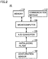
- Fig. 2 is a diagram showing a configuration of measurement instrument 20.
- measurement instrument 20 includes an acceleration sensor 102, an antialiasing filter 104, an A/D converter 106, a microcomputer 108, a memory 110, and a communication module 112.
- Acceleration sensor 102 is attached to a housing in which rolling bearing 15 ( Fig. 1 ) subjected to measurement is contained, and it detects, and provides output of, an acceleration of vibration produced in rolling bearing 15.
- Antialiasing filter 104 is a low-pass filter that suppresses aliasing produced in A/D conversion in A/D converter 106.
- A/D converter 106 converts a measurement signal (an analog signal) that has passed through antialiasing filter 104 to a digital signal.
- Microcomputer 108 receives acceleration data converted to the digital signal by A/D converter 106 and provides the acceleration data to memory 110. Then, as a prescribed amount of data is accumulated in memory 110, microcomputer 108 reads accumulated data from memory 110 and communication module 112 transmits the data to portable information terminal 30 as measurement data obtained by measurement instrument 20.
- Memory 110 receives acceleration data converted to the digital signal by A/D converter 106 from microcomputer 108, and the acceleration data is temporarily stored in memory 110.
- Communication module 112 is a wireless module for measurement instrument 20 to wirelessly communicate with portable information terminal 30.
- Fig. 3 is a diagram showing a configuration of portable information terminal 30.
- portable information terminal 30 includes a setting unit 202, a communication unit 204, an analyzer 206, a database (DB) unit 208, a determination unit 210, a display 212, and a central processing unit 214.
- DB database
- Setting unit 202 sets information on rolling bearing 15 ( Fig. 1 ) subjected to measurement. Though the set information is entered by a user on a screen of portable information terminal 30 in the present first embodiment, it may be stored in advance in DB unit 208 and read from DB unit 208 at the time of start of measurement of vibration by vibration measurement system 10.
- Information on rolling bearing 15 includes a bearing model number of rolling bearing 15 and a rotation speed or a rotation frequency of rolling bearing 15 in measurement by measurement instrument 20.
- specification data of various bearings that can be subjected to vibration measurement by vibration measurement system 10 is stored in advance in DB unit 208 as being associated with the bearing model numbers. Then, the specification data of the bearing having the bearing model number set by setting unit 202 is read from DB unit 208. Setting unit 202, however, may directly set the specification data of rolling bearing 15 as information on rolling bearing 15.
- Setting unit 202 further sets a criterion value for determination by determination unit 210, of a vibration state of rolling bearing 15 subjected to measurement. Though this criterion value is also entered by the user on the screen of portable information terminal 30 in the present first embodiment, it may be stored in advance in DB unit 208 and may be read from DB unit 208 at the time of start of vibration measurement by vibration measurement system 10.
- Communication unit 204 is a unit for portable information terminal 30 to establish wireless communication with measurement instrument 20, and it is implemented by a wireless module. Communication unit 204 transmits a measurement start signal to measurement instrument 20 at the time of start of vibration measurement by vibration measurement system 10 in response to an instruction from central processing unit 214. Communication unit 204 receives measurement data (acceleration data) transmitted from measurement instrument 20.
- Analyzer 206 conducts frequency analysis of measurement data (acceleration data) received by communication unit 204.
- analyzer 206 performs fast Fourier transform (FFT) processing on time-series acceleration data received by communication unit 204 and generates a frequency spectrum of the measurement data (acceleration data).
- FFT fast Fourier transform
- Specification data of various bearings that can be subjected to vibration measurement by this vibration measurement system 10 is stored in DB unit 208 as being associated with the bearing model numbers.
- the specification data includes at least data from which the ball pass frequency of inner ring (BPFI), the ball pass frequency of outer ring (BPFO), and the ball spin frequency (BSF) shown in expressions (1) to (3) below can be calculated.
- BPFI Z 2 f 0 1 + d D cos ⁇
- BPFO Z 2 f 0 1 ⁇ d D cos ⁇
- BSF f 0 D 2 d 1 ⁇ d D 2 cos 2 ⁇
- D represents a diameter of a pitch circle of the bearing
- d represents a diameter of the rolling element
- ⁇ represents a contact angle of the rolling element
- Z represents the number of rolling elements.
- f0 represents a rotation frequency of an inner ring shaft and is set by setting unit 202. Alternatively, when setting unit 202 sets the rotation speed, f0 is calculated from the rotation speed.
- At least the specification data including diameter D of the pitch circle, diameter d of the rolling element, contact angle ⁇ of the rolling element, and the number Z of rolling elements is stored in DB unit 208 as being associated with the bearing model number.
- coefficients Cin, Cout, and Crol of rotation frequency f0 for calculating the BPFI, the BPFO, and the BSF may be stored in DB unit 208.
- Coefficients Cin, Cout, and Crol are shown in expressions (4) to (6) below. [Expression 2]
- C in Z 2 1 + d D cos ⁇
- Central processing unit 214 calculates the BPFI, the BPFO, and the BSF of rolling bearing 15 in measurement based on the information on rolling bearing 15 set by setting unit 202. Specifically, central processing unit 214 reads the specification data of the bearing corresponding to the bearing model number set by setting unit 202 from DB unit 208 and calculates the BPFI, the BPFO, and the BSF in accordance with the expressions (1) to (3) based on the read specification data and the rotation speed (or the rotation frequency) set by setting unit 202.
- central processing unit 214 specifies a part for each peak. More specifically, a peak having a frequency (which is referred to as a "peak frequency" below) that matches with the BPFI and a higher-order component thereof is specified as indicating a fault of the inner ring. A peak having a peak frequency that matches with the BPFO and a higher-order component thereof is specified as indicating a fault of the outer ring, and a peak having a peak frequency that matches with the BSF and a higher-order component thereof is specified as indicating a fault of the rolling element.
- a peak having a peak frequency that matches with the rotation frequency of the shaft and a higher-order component thereof is specified as indicating imbalance in the shaft, and a peak having a peak frequency that matches with a frequency twice as high as the rotation frequency and a higher-order component thereof is specified as indicating misalignment.
- a peak having a peak frequency that matches with a frequency twice as high as the rotation frequency and a higher-order component thereof is specified as indicating misalignment.
- Determination unit 210 determines the vibration state for each peak based on the peak value (acceleration) of the peak frequency and the criterion value set by setting unit 202. For example, determination unit 210 determines a peak having a peak value exceeding the criterion value as "danger”. Determination unit 210 determines a peak having a peak value smaller than the criterion value but exceeding eighty percent of the criterion value as "caution”, and determines a peak having a peak value smaller than eighty percent of the criterion value as "good”.
- Display 212 shows, for peaks having top ten peak values, the peak value, the part, and the result of determination ("danger”, “caution”, “good”, and the like) by determination unit 210 on a screen of portable information terminal 30.
- the number of shown peaks is not limited to ten, but may be set to other numbers or may be set by a user on the screen of portable information terminal 30 with the default being ten.
- central processing unit 214 specifies a part for the peaks having the top ten peak values, and determination unit 210 determines the vibration state for the peaks having the top ten peak values.
- Central processing unit 214 may specify the part for all specified peaks and determination unit 210 may determine the vibration state for all specified peaks.
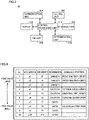
- Fig. 4 is a diagram showing exemplary representation by display 212.
- Fig. 4 shows the screen of portable information terminal 30 on which representation information is shown by display 212.
- the peak value (acceleration), the peak frequency, the result of determination by determination unit 210, and the part (damaged portion) are shown in the descending order of magnitude of the peak values (acceleration) (a1 > a2 > ... > a10).
- the shown peaks include also a peak of a higher-order component ("rotation second-order,” "outer ring second-order,” and the like).
- representation is given in the descending order of magnitude of the peak values in the present example, representation may be given in the ascending order of magnitude of the frequency (f1 ⁇ f2 ⁇ ... ⁇ f10).
- a color used for representation may be different (for example, “danger” shown with red, “caution” shown with yellow, and "good” shown with green).
- Fig. 5 is a diagram showing exemplary information set by setting unit 202.
- Information set by setting unit 202 can be entered by a user on the screen of portable information terminal 30, and Fig. 5 shows the screen of portable information terminal 30 for entry of information by the user.
- the bearing model number of rolling bearing 15 ( Fig. 1 ) subjected to measurement can be entered in an input section 310.
- a rotation speed (min -1 ) of the shaft in measurement can be entered in an input section 320. Since vibration measurement system 10 is not provided with a sensor that detects the rotation speed of the shaft in measurement by measurement instrument 20, information on the rotation speed should be obtained and entered in input section 320 in measurement. When a rotation speed sensor is annexed, however, input section 320 does not have to be provided. The rotation frequency of the shaft in measurement instead of the rotation speed of the shaft in measurement may be entered in input section 320.
- a criterion value (acceleration) to be used by determination unit 210 can be entered in an input section 330.
- the criterion value is set to a uniform value regardless of the peak frequency.
- the number of peaks having largest peak values to be shown by display 212 can be entered in an input section 340.
- the number of peaks to be shown by display 212 is set in accordance with this input value.
- a default value for example, ten is set.
- Fig. 6 is a flowchart showing an exemplary procedure in processing in measurement instrument 20.
- microcomputer 108 when power of measurement instrument 20 is turned on, microcomputer 108 performs prescribed initialization processing (step S10).
- initialization processing for example, communication between communication module 112 and portable information terminal 30 is established and data in memory 110 is cleared.
- microcomputer 108 determines whether or not it has received a measurement start signal from portable information terminal 30 (step S20). Then, when microcomputer 108 has received the measurement start signal (YES in step S20), it reads from A/D converter 106, an output from acceleration sensor 102 that has passed through antialiasing filter 104 and digitally converted by A/D converter 106 (step S30).
- Microcomputer 108 has data read from A/D converter 106 temporarily stored in memory 110 (step S40). Then, microcomputer 108 determines whether or not the number of pieces of obtained data has reached a prescribed number (step S50). When the number of pieces of obtained data has not reached the prescribed number (NO in step S50), microcomputer 108 repeats processing in steps S30 and S40.
- microcomputer 108 determines in step S50 that the number of pieces of obtained data has reached the prescribed number (YES in step S50)
- microcomputer 108 reads obtained data from memory 110 and transmits the data to portable information terminal 30 by means of communication module 112 (step S60).
- microcomputer 108 determines whether or not the user has performed a quitting operation to quit measurement (step S70).
- the quitting operation is performed onto portable information terminal 30, and when the microcomputer receives a measurement quitting signal from portable information terminal 30, it determines that the quitting operation has been performed.
- step S70 When the microcomputer determines that the quitting operation has not been performed (NO in step S70), the process returns to step S20. When the microcomputer determines that the quitting operation has been performed (YES in step S70), the process proceeds to end and a series of processing in measurement instrument 20 ends.
- Fig. 7 is a flowchart showing an exemplary procedure in processing in portable information terminal 30.
- central processing unit 214 performs prescribed initialization processing (step S110).
- the initialization processing for example, communication between communication unit 204 and measurement instrument 20 is established and prescribed resetting processing is performed.
- setting unit 202 sets the bearing model number of rolling bearing 15 subjected to measurement, the rotation speed (or the rotation frequency) in measurement, the criterion value for determining the vibration state based on measurement data, and the like (step S115).
- Each set value is entered by a user on the screen of portable information terminal 30.
- central processing unit 214 reads specification data of the bearing corresponding to the set bearing model number from DB unit 208 and calculates the BPFI, the BPFO, and the BSF of rolling bearing 15 subjected to measurement in accordance with the expressions (1) to (3) based on the specification data and the rotation frequency calculated from the set rotation speed (step S120). Thereafter, central processing unit 214 transmits the measurement start signal to measurement instrument 20 through communication unit 204 (step S125).
- central processing unit 214 determines whether or not it has received measurement data (acceleration data) from measurement instrument 20 (step S130). Then, when central processing unit 214 has received the measurement data from measurement instrument 20 (YES in step S130), it has the received measurement data stored in the memory (not shown) (step S135).
- central processing unit 214 determines whether or not the number of pieces of measurement data received from measurement instrument 20 has reached a prescribed number (step S140). When the number of pieces of data has not reached the prescribed number (NO in step S140), the central processing unit repeats processing in steps S130 and S135.
- central processing unit 214 determines in step S140 that the number of pieces of data has reached the prescribed number (YES in step S140), it reads data from the memory and has analyzer 206 conduct frequency analysis of data (acceleration data) resulting from measurement by measurement instrument 20 (step S145). Specifically, fast Fourier transform (FFT) processing is performed on time-series acceleration data obtained by measurement by measurement instrument 20 to obtain a frequency spectrum of the obtained acceleration data.
- FFT fast Fourier transform
- central processing unit 214 extracts top ten peak values and specifies a part corresponding to the peak frequency for the extracted top ten peaks. Specifically, central processing unit 214 specifies for each of the extracted peaks, from which of a fault of the inner ring, a fault of the outer ring, a fault of the rolling element, imbalance of the shaft, and misalignment the peak is derived based on whether or not the peak frequency matches with any of the BPFI, the BPFO, the BSF, and a higher-order component thereof or whether or not it matches with any of the rotation frequency of the shaft, the frequency twice as high as that, and a higher-order component thereof. Then, for each specified part, central processing unit 214 has determination unit 210 determine the vibration state of each part based on the set criterion value (step S150).
- determination unit 210 determines a peak having the peak value exceeding the criterion value as "danger”. Determination unit 210 determines a peak having the peak value smaller than the criterion value but exceeding eighty percent of the criterion value as "caution” and determines a peak having the peak value smaller than eighty percent of the criterion value as "good”.
- central processing unit 214 has display 212 show the result of determination in step S150, the peak value, the peak frequency, and the part on the screen of portable information terminal 30 together with a waveform of the frequency spectrum (step S155).
- central processing unit 214 determines whether or not the user has performed the quitting operation to quit measurement (step S160). When the central processing unit determines that the quitting operation has not been performed (NO in step S160), the process returns to step S115. When the central processing unit determines that the quitting operation has been performed (YES in step S160), the process proceeds to end and a series of processing in portable information terminal 30 ends.
- the peak value (acceleration), the peak frequency, the result of determination of the vibration state ("danger”, “caution”, “good”, and the like), and the part (damaged portion) are shown on the screen of portable information terminal 30.
- the user can thus readily know, for a peak large in vibration, magnitude thereof, the part, and the vibration state of the part.
- the user can set the number of peaks to be shown, and hence representation as desired by the user can be realized. Since measurement instrument 20 and portable information terminal 30 wirelessly communicate with each other, the user can check a result of vibration analysis at any location within an area where wireless communication can be established, simply by installing measurement instrument 20 in a measurement target.
- the criterion value for determining the vibration state ("danger”, “caution”, “good”, and the like) is uniformly set regardless of a frequency.
- the criterion value is set for each frequency band.
- An overall configuration of the vibration measurement system according to this second embodiment is similar to that in the first embodiment shown in Figs. 1 to 3 .
- Fig. 8 is a diagram showing an exemplary criterion value in the second embodiment.
- the abscissa represents a frequency and the ordinate represents an acceleration (vibration).
- a waveform represents an exemplary result of frequency analysis conducted by analyzer 206.
- ten frequency bands equal in width are set from a frequency 0, and the criterion value is set for each frequency band.
- the number of frequency bands, however, is not limited to ten, and the width of each frequency band does not necessarily have to be equal either.
- the width and the number of frequency bands may be set with the width of each frequency band being set to be equal, or an upper limit of a frequency to be analyzed may be set with the number of frequency bands being set to a certain number.
- Fig. 9 is a diagram showing exemplary information set by setting unit 202 in the second embodiment.
- the user can enter the information set by setting unit 202 on the screen of portable information terminal 30, and Fig. 9 shows the screen of portable information terminal 30 for entry of information by the user.
- the bearing model number of rolling bearing 15 ( Fig. 1 ) subjected to measurement can be entered.
- a rotation speed (min -1 ) of the shaft in measurement can be entered.
- the rotation frequency of the shaft in measurement instead of the rotation speed of the shaft in measurement may be entered in input section 420.
- an input section 430 for determination as to the vibration state to be made based on the criterion value set for each frequency band, in setting an equal width of the frequency band, that width of the frequency band can be entered.
- an input section 440 in setting the certain number of frequency bands, the upper limit of the frequency to be analyzed can be entered. The user should only provide entry into any one of input sections 430 and 440. If entry is provided into both of input sections 430 and 440, a value in predetermined one of them (for example, input section 430) is adopted.
- the number of frequency bands can be entered.
- frequency band(s) having the frequency bandwidth as many as the number entered into input section 450 is (are) set.
- the upper limit frequency has been set by entry into input section 440, by dividing the upper limit frequency by the number entered into input section 450, the frequency band(s) as many as the number entered into input section 450 is (are) set.
- the criterion value can be set for each frequency band.
- each frequency band set based on the frequency bandwidth entered in input section 430 or the upper limit frequency entered in input section 440 and on the number of frequency bands entered in input section 450 is shown, and the criterion value is shown for each frequency band.
- the criterion value shown in input section 460 can be moved up and down by using an input device (a mouse, a touch panel, or the like). The user can set in input section 460, the criterion value for each frequency band by using the input device.
- Fig. 10 is a flowchart showing an exemplary procedure in processing in portable information terminal 30 in the second embodiment.
- central processing unit 214 performs prescribed initialization processing (step S210). This initialization processing is the same as the processing performed in step S110 in Fig. 7 .
- setting unit 202 sets the bearing model number of rolling bearing 15 subjected to measurement, the rotation speed (or the rotation frequency) in measurement, and the like (step S215). Each set value is entered by a user on the screen of portable information terminal 30.
- setting unit 202 sets the criterion value for each frequency band (step S220). As described with reference to Fig. 9 , each frequency band is set based on input values in input sections 430 and 450, and the criterion value for each frequency band is set based on entry into input section 460.
- step S220 When the criterion value is set for each frequency band in step S220, the process proceeds to step S225. Since processing in steps S225 to S250 is the same as the processing in steps S120 to S145 in Fig. 7 , description will not be repeated.
- central processing unit 214 has determination unit 210 determine the vibration state of rolling bearing 15 for each frequency band based on the criterion value for each frequency band set in step S220 (step S255).
- central processing unit 214 specifies a part corresponding to the peak (step S260). Specifically, central processing unit 214 specifies, for each peak having the peak value exceeding the criterion value, from which of a fault of the inner ring, a fault of the outer ring, a fault of the rolling element, imbalance of the shaft, and misalignment the peak is derived based on whether or not the peak frequency matches with any of the BPFI, the BPFO, the BSF, and a higher-order component thereof or whether or not it matches with any of the rotation frequency of the shaft, the frequency twice as high as that, and a higher-order component thereof.
- central processing unit 214 has display 212 show the result of determination in step S255, the peak value, the peak frequency, and the part on the screen of portable information terminal 30, together with a waveform of the frequency spectrum (step S265).
- central processing unit 214 determines whether or not the user has performed the quitting operation to quit measurement (step S270). When the central processing unit determines that the quitting operation has not been performed (NO in step S270), the process returns to step S215. When the central processing unit determines that the quitting operation has been performed (YES in step S270), the process proceeds to end and a series of processing in portable information terminal 30 ends.
- the criterion value is set for each frequency band, and in each frequency band, the vibration state is determined based on the peak value of the frequency spectrum and the criterion value.
- diagnosis is conducted based not on a specific frequency component produced by an abnormal condition (a fault of the inner ring, the outer ring, the rolling element, or the cage) of the bearing, but on an appropriate criterion value for each set frequency band. Therefore, according to this second embodiment, a result of diagnosis for a frequency band to which a user desires to pay attention can be provided.
- measurement instrument 20 and portable information terminal 30 wirelessly communicate with each other also in this second embodiment, the user can check a result of vibration analysis at any location within an area where wireless communication can be established simply by installing measurement instrument 20 in a measurement target.
- An overall configuration of the vibration measurement system according to a third embodiment is similar to that in the first embodiment shown in Figs. 1 to 3 .
- DB unit 208 data on a coefficient of a rotation frequency (a plurality of constants obtained by dividing the coefficient) of the bearing for calculating a damage frequency for specifying a damaged part of the bearing in accordance with a prescribed arithmetic expression based on specification data of the bearing is stored in DB unit 208 as being associated with a bearing model number. Then, the data corresponding to the bearing model number set by setting unit 202 is read from DB unit 208, the damage frequency is calculated based on the read data, and the damaged part is specified.
- DB unit 208 data on the coefficient of the rotation frequency of the shaft for calculation of a ball pass frequency of inner ring (BPFI), a ball pass frequency of outer ring (BPFO), and a ball spin frequency (BSF) of rolling bearing 15 subjected to measurement is stored in DB unit 208 as being associated with the bearing model number.
- BPFI ball pass frequency of inner ring
- BPFO ball pass frequency of outer ring
- BSF ball spin frequency
- the server is not used but portable information terminal 30 specifies a damaged part. Therefore, the coefficient of the rotation frequency of the bearing for calculating the BPFI, the BPFO, and the BSF of rolling bearing 15 subjected to measurement should be held in portable information terminal 30.
- D represents a diameter of a pitch circle of the bearing
- d represents a diameter of the rolling element
- ⁇ represents a contact angle of the rolling element
- Z represents the number of rolling elements, and each value corresponds to the specifications of rolling bearing 15.
- Rotation frequency f0 corresponds to a measurement condition, and is set by setting unit 202.
- rotation frequency f0 is calculated from the set rotation speed.
- Coefficients Cin, Cout, and Crol of rotation frequency f0 are calculated based on the specifications (diameter D of the pitch circle of the bearing, diameter d of the rolling element, contact angle ⁇ of the rolling element, and the number Z of rolling elements) of rolling bearing 15.
- the specification data (diameter D of the pitch circle of the bearing, diameter d of the rolling element, contact angle ⁇ of the rolling element, and the number Z of rolling elements) of rolling bearing 15 or coefficients Cin, Cout, and Crol calculated based on the specification data should be held in portable information terminal 30.
- each of coefficients Cin, Cout, and Crol is stored in DB unit 208 of portable information terminal 30 as being divided into a plurality of constants.
- central processing unit 214 calculates the BPFI, the BPFO, and the BSF of rolling bearing 15 in measurement based on the information on rolling bearing 15 set by setting unit 202. Specifically, central processing unit 214 reads the plurality of constants Ca to Cd corresponding to the bearing model number set by setting unit 202 from DB unit 208 and restores coefficients Cin, Cout, and Crol in accordance with the expressions (10) to (12) from the read plurality of constants Ca to Cd.
- central processing unit 214 calculates the BPFI, the BPFO, and the BSF in accordance with the expressions (7) to (9) based on restored coefficients Cin, Cout, and Crol and the rotation speed (or the rotation frequency) set by setting unit 202.
- display 212 shows the peak value, the part, and the result of determination ("danger”, “caution”, “good”, and the like) by determination unit 210 on the screen of portable information terminal 30.
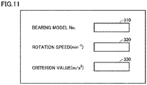
- Fig. 11 is a diagram showing exemplary information set by setting unit 202 in the third embodiment.
- Information set by setting unit 202 can be entered by a user on the screen of portable information terminal 30, and Fig. 11 shows the screen of portable information terminal 30 for entry of information by the user.
- the bearing model number of rolling bearing 15 ( Fig. 1 ) subjected to measurement can be entered in input section 310.
- a rotation speed (min -1 ) of the shaft in measurement can be entered in input section 320. Since vibration measurement system 10 is not provided with a sensor that detects the rotation speed of the shaft in measurement by measurement instrument 20, information on the rotation speed should be obtained and entered in input section 320 in measurement. When a rotation speed sensor is annexed, however, input section 320 does not have to be provided. The rotation frequency of the shaft in measurement instead of the rotation speed of the shaft in measurement may be entered in input section 320.
- a criterion value (acceleration) to be used by determination unit 210 can be entered in input section 330.
- the criterion value is set to a uniform value regardless of the peak frequency.
- Fig. 12 is a diagram showing exemplary data stored in DB unit 208 in the third embodiment.
- the plurality of constants Ca to Cd obtained by division of coefficients Cin, Cout, and Crol for calculating the BPFI, the BPFO, and the BSF are stored in DB unit 208 as being associated with the bearing model number for each bearing that can be subjected to vibration measurement by vibration measurement system 10. Even if such constants Ca to Cd may be leaked to the outside of portable information terminal 30, elucidation of the specifications of the bearing can be prevented.
- Fig. 13 is a flowchart showing an exemplary procedure in processing in portable information terminal 30.
- central processing unit 214 performs prescribed initialization processing (step S310).
- the initialization processing for example, communication between communication unit 204 and measurement instrument 20 is established and prescribed resetting processing is performed.
- setting unit 202 sets the bearing model number of rolling bearing 15 subjected to measurement, the rotation speed (or the rotation frequency) in measurement, the criterion value for determining the vibration state based on measurement data, and the like (step S315).
- Each set value is entered by a user on the screen of portable information terminal 30.
- central processing unit 214 reads constants Ca to Cd (divided constants) of the bearing corresponding to the set bearing model number from DB unit 208 and restores coefficients Cin, Cout, and Crol in accordance with the expressions (10) to (12) from read constants Ca to Cd (step S320).
- central processing unit 214 calculates the BPFI, the BPFO, and the BSF of rolling bearing 15 subjected to measurement in accordance with the expressions (7) to (9) based on restored coefficients Cin, Cout, and Crol and the rotation frequency calculated from the rotation speed set in step S315 (step S322). Thereafter, central processing unit 214 transmits the measurement start signal to measurement instrument 20 through communication unit 204 (step S325).
- central processing unit 214 determines whether or not it has received measurement data (acceleration data) from measurement instrument 20 (step S330). Then, when central processing unit 214 has received the measurement data (YES in step S330), it has the received measurement data stored in the memory (not shown) (step S335).
- central processing unit 214 determines whether or not the number of pieces of measurement data received from measurement instrument 20 has reached a prescribed number (step S340). When the number of pieces of data has not reached the prescribed number (NO in step S340), the central processing unit repeats processing in steps S330 and S335.
- central processing unit 214 determines in step S340 that the number of pieces of data has reached the prescribed number (YES in step S340), it reads data from the memory and has analyzer 206 conduct frequency analysis of data (acceleration data) obtained by measurement by measurement instrument 20 (step S345). Specifically, fast Fourier transform (FFT) processing is performed on time-series acceleration data obtained by measurement by measurement instrument 20 to obtain a frequency spectrum of obtained acceleration data.
- FFT fast Fourier transform
- central processing unit 214 specifies from which of a fault of the inner ring, a fault of the outer ring, a fault of the rolling element, imbalance of the shaft, and misalignment the peak is derived based on whether or not the peak frequency matches with any of the BPFI, the BPFO, the BSF, and a higher-order component thereof or whether or not it matches with any of the rotation frequency of the shaft, the frequency twice as high as that, and a higher-order component thereof. Then, for each specified part, central processing unit 214 has determination unit 210 determine the vibration state of each part based on the criterion value set in step S315 (step S350).
- determination unit 210 determines a peak having the peak value exceeding the criterion value as "danger”. Determination unit 210 determines a peak having the peak value smaller than the criterion value but exceeding eighty percent of the criterion value as "caution” and determines a peak having the peak value smaller than eighty percent of the criterion value as "good”.
- central processing unit 214 has display 212 show the result of determination in step S350, the peak value, the peak frequency, and the part on the screen of portable information terminal 30, together with a waveform of the frequency spectrum (step S355).
- central processing unit 214 determines whether or not the user has performed the quitting operation to quit measurement (step S360). When the central processing unit determines that the quitting operation has not been performed (NO in step S360), the process returns to step S315. When the central processing unit determines that the quitting operation has been performed (YES in step S360), the process proceeds to end and a series of processing in portable information terminal 30 ends.
- coefficients Cin, Cout, and Crol for calculating the BPFI, the BPFO, and the BSF are stored in DB unit 208 as being divided into the plurality of constants Ca to Cd. Then, in vibration analysis, constants Ca to Cd are read from DB unit 208 to restore coefficients Cin, Cout, and Crol, and the BPFI, the BPFO, and the BSF are calculated based on restored coefficients Cin, Cout, and Crol.
- measurement instrument 20 and portable information terminal 30 wirelessly communicate with each other also in this third embodiment, the user can check a result of vibration analysis at any location within an area where wireless communication can be established simply by installing measurement instrument 20 in a measurement target.
- each of coefficients Cin, Cout, and Crol used for calculation of the BPFI, the BPFO, and the BSF is stored in DB unit 208 as being divided into the plurality of constants Ca to Cd.
- specification data (diameter D of the pitch circle of the bearing, diameter d of the rolling element, contact angle ⁇ of the rolling element, and the number Z of rolling elements) of rolling bearing 15 subjected to measurement is stored in DB unit 208 as being encrypted. Then, in measurement, the encrypted specification data is read from DB unit 208 and decrypted to calculate the BPFI, the BPFO, and the BSF.
- An overall configuration of the vibration measurement system according to this fourth embodiment is similar to that in the first embodiment shown in Figs. 1 and 2 .
- Fig. 14 is a diagram showing a configuration of portable information terminal 30 in the fourth embodiment.
- portable information terminal 30 in the fourth embodiment further includes an encryption processing unit 216.
- specification data encrypted in accordance with prescribed cryptography is stored in DB unit 208 as being associated with bearing model numbers.
- Symmetric key cryptography or public key cryptography may be adopted as cryptography. Encryption may be done by using identical key encryption for various specifications or by using key encryption different for each specification.
- Various known approaches can be used for cryptography.
- encryption processing unit 216 reads specification data (encrypted data) corresponding to the bearing model number set by setting unit 202 from DB unit 208 and decrypts the read specification data by using key encryption in accordance with the cryptography.
- Central processing unit 214 calculates the BPFI, the BPFO, and the BSF in accordance with the expressions (7) to (9) based on the specification data decrypted by encryption processing unit 216 and the rotation speed (or the rotation frequency) set by setting unit 202. Processing by central processing unit 214 after calculation of the BPFI, the BPFO, and the BSF is the same as in the third embodiment.
- Fig. 15 is a flowchart showing an exemplary procedure in processing in portable information terminal 30 in the fourth embodiment.
- central processing unit 214 performs prescribed initialization processing (step S410).
- setting unit 202 sets the bearing model number of rolling bearing 15 subjected to measurement, the rotation speed (or the rotation frequency) in measurement, the criterion value for determining the vibration state based on measurement data, and the like (step S415).
- Processing performed in steps S410 and S415 is the same as the processing performed in steps S310 and S315 in Fig. 13 .
- the specification data (encrypted data) of the bearing corresponding to the set bearing model number is read from DB unit 208, and encryption processing unit 216 decrypts the encrypted specification data by using key encryption in accordance with prescribed cryptography (step S420).
- central processing unit 214 calculates the BPFI, the BPFO, and the BSF of rolling bearing 15 subjected to measurement in accordance with the expressions (7) to (9) based on the decrypted specification data and the rotation frequency calculated from the rotation speed set in step S415 (step S422).
- step S422 When the BPFI, the BPFO, and the BSF are calculated in step S422, the process proceeds to step S425. Since processing in steps S425 to S455 is the same as the processing in steps S325 to S355 in Fig. 13 , description will not be repeated.
- central processing unit 214 determines whether or not the user has performed the quitting operation to quit measurement (step S460). When the central processing unit determines that the quitting operation has not been performed (NO in step S460), the process returns to step S415. When the central processing unit determines that the quitting operation has been performed (YES in step S460), the process proceeds to end and a series of processing in portable information terminal 30 ends.
- specification data of rolling bearing 15 subjected to measurement is stored as being encrypted in DB unit 208. Then, in vibration analysis, the encrypted specification data is read from DB unit 208 and decrypted, and the BPFI, the BPFO, and the BSF are calculated based on the decrypted specification data.
- vibration analysis the encrypted specification data is read from DB unit 208 and decrypted, and the BPFI, the BPFO, and the BSF are calculated based on the decrypted specification data.
- measurement instrument 20 and portable information terminal 30 wirelessly communicate with each other also in this fourth embodiment, the user can check a result of vibration analysis at any location within an area where wireless communication can be established simply by installing measurement instrument 20 in a measurement target.
- coefficients Cin, Cout, and Crol for calculating the BPFI, the BPFO, and the BSF may be stored in DB unit 208 as being encrypted, or the plurality of constants Ca to Cd obtained by division of coefficients Cin, Cout, and Crol described in the third embodiment may be stored in DB unit 208 as being encrypted.
- the plurality of constants Ca to Cd may be stored in DB unit 208 in a binary format. Elucidation of the specifications of the bearing that can be subjected to measurement by vibration measurement system 10 in the event of leakage of data stored in DB unit 208 to the outside of portable information terminal 30 can thus also be prevented.
- the specification data in the binary format may be stored in DB unit 208 as being encrypted.
- coefficients Cin, Cout, and Crol in the binary format or the plurality of constants Ca to Cd in the binary format may be stored in DB unit 208 as being encrypted.
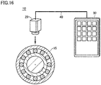
- measurement instrument 20 and portable information terminal 30 wirelessly communicate with each other in each embodiment above, measurement instrument 20 and portable information terminal 30 may be connected to each other through a communication line 40 as shown in Fig. 16 , and measurement instrument 20 and portable information terminal 30 may communicate with each other through communication line 40.
- vibration measurement system 10 vibration measurement system; 15 measurement target (rolling bearing); 20 measurement instrument; 30 portable information terminal; 40 communication line; 102 acceleration sensor; 104 antialiasing filter; 106 A/D converter; 108 microcomputer; 110 memory; 112 communication module; 202 setting unit; 204 communication unit; 206 analyzer; 208 DB unit; 210 determination unit; 212 display; 214 central processing unit; 216 encryption processing unit; 310 to 340, 410 to 460 input section
Landscapes
- Physics & Mathematics (AREA)
- General Physics & Mathematics (AREA)
- Acoustics & Sound (AREA)
- Engineering & Computer Science (AREA)
- Computer Networks & Wireless Communication (AREA)
- Measurement Of Mechanical Vibrations Or Ultrasonic Waves (AREA)
- Testing Of Devices, Machine Parts, Or Other Structures Thereof (AREA)
Applications Claiming Priority (3)
| Application Number | Priority Date | Filing Date | Title |
|---|---|---|---|
| JP2019181804A JP7443011B2 (ja) | 2019-10-02 | 2019-10-02 | 振動解析装置及び振動測定システム |
| JP2019184541A JP7360887B2 (ja) | 2019-10-07 | 2019-10-07 | 振動解析装置及び振動測定システム |
| PCT/JP2020/035984 WO2021065663A1 (fr) | 2019-10-02 | 2020-09-24 | Dispositif d'analyse de vibrations et système de mesure de vibrations |
Publications (3)
| Publication Number | Publication Date |
|---|---|
| EP4043856A1 true EP4043856A1 (fr) | 2022-08-17 |
| EP4043856A4 EP4043856A4 (fr) | 2023-10-11 |
| EP4043856B1 EP4043856B1 (fr) | 2024-08-07 |
Family
ID=75337155
Family Applications (1)
| Application Number | Title | Priority Date | Filing Date |
|---|---|---|---|
| EP20871415.4A Active EP4043856B1 (fr) | 2019-10-02 | 2020-09-24 | Dispositif d'analyse de vibrations et système de mesure de vibrations |
Country Status (4)
| Country | Link |
|---|---|
| US (1) | US20220397484A1 (fr) |
| EP (1) | EP4043856B1 (fr) |
| CN (1) | CN114829895A (fr) |
| WO (1) | WO2021065663A1 (fr) |
Families Citing this family (2)
| Publication number | Priority date | Publication date | Assignee | Title |
|---|---|---|---|---|
| JP7710303B2 (ja) * | 2021-02-08 | 2025-07-18 | Ntn株式会社 | 振動分析装置および振動分析システム |
| WO2024004253A1 (fr) * | 2022-06-27 | 2024-01-04 | 東芝インフラシステムズ株式会社 | Dispositif de détermination de son anormal |
Family Cites Families (17)
| Publication number | Priority date | Publication date | Assignee | Title |
|---|---|---|---|---|
| JPS6293620A (ja) * | 1985-10-18 | 1987-04-30 | Kawasaki Steel Corp | 回転機診断器 |
| JP3225204B2 (ja) * | 1997-02-05 | 2001-11-05 | 株式会社東芝 | 回転機、回転機設備、輸送システム、加振構造物等の健全性確認検査装置および方法 |
| US6321602B1 (en) * | 1999-09-28 | 2001-11-27 | Rockwell Science Center, Llc | Condition based monitoring by vibrational analysis |
| WO2002037067A1 (fr) | 2000-11-06 | 2002-05-10 | Nsk Ltd. | Dispositif et procede diagnostiquant des anomalies pour une installation mecanique |
| JP2005233789A (ja) * | 2004-02-19 | 2005-09-02 | Nsk Ltd | 回転機械の異常診断方法、異常診断装置および異常診断システム |
| JP4818594B2 (ja) * | 2004-07-30 | 2011-11-16 | 住友重機械エンバイロメント株式会社 | 有機酸生成方法、有機酸生成装置及び排水処理装置 |
| WO2006030786A1 (fr) * | 2004-09-13 | 2006-03-23 | Nsk Ltd. | Dispositif de diagnostic d’anomalie et procede de diagnostic d’anomalie |
| JP2006113002A (ja) * | 2004-10-18 | 2006-04-27 | Nsk Ltd | 機械設備の異常診断システム |
| WO2006043511A1 (fr) * | 2004-10-18 | 2006-04-27 | Nsk Ltd. | Systeme de diagnostic d’anomalie pour une machinerie |
| US7222048B2 (en) * | 2005-04-21 | 2007-05-22 | General Electric Company | Methods and systems for diagnosing machinery |
| JP4935157B2 (ja) * | 2006-04-07 | 2012-05-23 | 日本精工株式会社 | 異常診断装置および異常診断方法 |
| KR100874870B1 (ko) * | 2007-08-09 | 2008-12-19 | 울산대학교 산학협력단 | 영역분할기법을 이용한 피크 코드의 부여방법과 그 피크코드 및 그 피크 코드를 이용한 기계장치의 고장예측진단방법 |
| EP2543977B8 (fr) * | 2010-03-03 | 2019-06-26 | Asahi Kasei Engineering Corporation | Procédé de diagnostic et dispositif de diagnostic pour un palier lisse |
| JP2016024007A (ja) | 2014-07-18 | 2016-02-08 | Ntn株式会社 | 機械部品診断システムおよびそのサーバ |
| GB2543521A (en) * | 2015-10-20 | 2017-04-26 | Skf Ab | Method and data processing device for severity assessment of bearing defects using vibration energy |
| US11506569B2 (en) * | 2019-01-15 | 2022-11-22 | Computational Systems, Inc. | Bearing and fault frequency identification from vibration spectral plots |
| CN110160767B (zh) * | 2019-06-14 | 2021-03-02 | 安徽智寰科技有限公司 | 基于包络分析的冲击周期自动识别与提取方法及系统 |
-
2020
- 2020-09-24 WO PCT/JP2020/035984 patent/WO2021065663A1/fr not_active Ceased
- 2020-09-24 EP EP20871415.4A patent/EP4043856B1/fr active Active
- 2020-09-24 US US17/765,350 patent/US20220397484A1/en not_active Abandoned
- 2020-09-24 CN CN202080083260.3A patent/CN114829895A/zh active Pending
Also Published As
| Publication number | Publication date |
|---|---|
| EP4043856B1 (fr) | 2024-08-07 |
| WO2021065663A1 (fr) | 2021-04-08 |
| US20220397484A1 (en) | 2022-12-15 |
| CN114829895A (zh) | 2022-07-29 |
| EP4043856A4 (fr) | 2023-10-11 |
Similar Documents
| Publication | Publication Date | Title |
|---|---|---|
| EP3648338B1 (fr) | Dispositif de diagnostic de moteur électrique | |
| EP3611489B1 (fr) | Dispositif de surveillance d'état, système de surveillance d'état et procédé de surveillance d'état | |
| CN101464212B (zh) | 风力涡轮机的基于振动自动情况监测方法和设备 | |
| EP1338873A1 (fr) | Dispositif et procede diagnostiquant des anomalies pour une installation mecanique | |
| EP4043856B1 (fr) | Dispositif d'analyse de vibrations et système de mesure de vibrations | |
| JP5293300B2 (ja) | 回転機の振動監視装置および振動監視方法 | |
| EP3173763A1 (fr) | Système de diagnostic de composant de machine et son serveur | |
| EP3605037A1 (fr) | Terminal d'informations et système de diagnostic d'élément de machine | |
| EP3575908A1 (fr) | Procédé de contrôle d'état et dispositif de contrôle d'état | |
| EP4234927B1 (fr) | Système de surveillance d'état et éolienne le comprenant | |
| CN105829857A (zh) | 旋转机械部件的利用便携终端的检查系统和检查方法 | |
| EP3842780A1 (fr) | Procédé et dispositif de diagnostic d'une anomalie au sein d'un palier à roulement | |
| CN116541800A (zh) | 基于振动和声音数据的融合诊断方法、系统、设备及介质 | |
| JP7360887B2 (ja) | 振動解析装置及び振動測定システム | |
| CN115499458A (zh) | 基于物联网的振动监测方法、装置、设备及存储介质 | |
| CN113383216A (zh) | 分析装置、分析方法和程序 | |
| CN116170717B (zh) | 复杂噪声环境下耳机降噪测试方法、装置及电子设备 | |
| JP6897064B2 (ja) | 軸受異常診断方法および診断システム | |
| JP6869156B2 (ja) | 状態監視装置および状態監視方法 | |
| JP7443011B2 (ja) | 振動解析装置及び振動測定システム | |
| CN115656700B (zh) | 检测方法、训练方法、电器、监控系统和存储介质 | |
| EP3748154A1 (fr) | Procédé de surveillance mise en uvre par ordinateur d'un composent d'une éolienne | |
| JP2018179977A (ja) | 状態監視装置、状態監視システムおよび状態監視方法 | |
| JP7631131B2 (ja) | 機器状態監視装置、風力発電システムおよび機器状態監視方法 | |
| KR20240054028A (ko) | 선박용 모터의 구름 베어링 결함 진단 장치 |
Legal Events
| Date | Code | Title | Description |
|---|---|---|---|
| STAA | Information on the status of an ep patent application or granted ep patent |
Free format text: STATUS: THE INTERNATIONAL PUBLICATION HAS BEEN MADE |
|
| PUAI | Public reference made under article 153(3) epc to a published international application that has entered the european phase |
Free format text: ORIGINAL CODE: 0009012 |
|
| STAA | Information on the status of an ep patent application or granted ep patent |
Free format text: STATUS: REQUEST FOR EXAMINATION WAS MADE |
|
| 17P | Request for examination filed |
Effective date: 20220419 |
|
| AK | Designated contracting states |
Kind code of ref document: A1 Designated state(s): AL AT BE BG CH CY CZ DE DK EE ES FI FR GB GR HR HU IE IS IT LI LT LU LV MC MK MT NL NO PL PT RO RS SE SI SK SM TR |
|
| DAV | Request for validation of the european patent (deleted) | ||
| DAX | Request for extension of the european patent (deleted) | ||
| A4 | Supplementary search report drawn up and despatched |
Effective date: 20230908 |
|
| RIC1 | Information provided on ipc code assigned before grant |
Ipc: G08C 19/00 20060101ALI20230904BHEP Ipc: G01H 17/00 20060101ALI20230904BHEP Ipc: G01M 13/045 20190101AFI20230904BHEP |
|
| GRAP | Despatch of communication of intention to grant a patent |
Free format text: ORIGINAL CODE: EPIDOSNIGR1 |
|
| STAA | Information on the status of an ep patent application or granted ep patent |
Free format text: STATUS: GRANT OF PATENT IS INTENDED |
|
| INTG | Intention to grant announced |
Effective date: 20240321 |
|
| GRAS | Grant fee paid |
Free format text: ORIGINAL CODE: EPIDOSNIGR3 |
|
| GRAA | (expected) grant |
Free format text: ORIGINAL CODE: 0009210 |
|
| STAA | Information on the status of an ep patent application or granted ep patent |
Free format text: STATUS: THE PATENT HAS BEEN GRANTED |
|
| AK | Designated contracting states |
Kind code of ref document: B1 Designated state(s): AL AT BE BG CH CY CZ DE DK EE ES FI FR GB GR HR HU IE IS IT LI LT LU LV MC MK MT NL NO PL PT RO RS SE SI SK SM TR |
|
| REG | Reference to a national code |
Ref country code: GB Ref legal event code: FG4D |
|
| REG | Reference to a national code |
Ref country code: CH Ref legal event code: EP |
|
| REG | Reference to a national code |
Ref country code: DE Ref legal event code: R096 Ref document number: 602020035528 Country of ref document: DE |
|
| REG | Reference to a national code |
Ref country code: IE Ref legal event code: FG4D |
|
| REG | Reference to a national code |
Ref country code: LT Ref legal event code: MG9D |
|
| REG | Reference to a national code |
Ref country code: NL Ref legal event code: MP Effective date: 20240807 |
|
| PG25 | Lapsed in a contracting state [announced via postgrant information from national office to epo] |
Ref country code: NO Free format text: LAPSE BECAUSE OF FAILURE TO SUBMIT A TRANSLATION OF THE DESCRIPTION OR TO PAY THE FEE WITHIN THE PRESCRIBED TIME-LIMIT Effective date: 20241107 |
|
| REG | Reference to a national code |
Ref country code: AT Ref legal event code: MK05 Ref document number: 1711454 Country of ref document: AT Kind code of ref document: T Effective date: 20240807 |
|
| PG25 | Lapsed in a contracting state [announced via postgrant information from national office to epo] |
Ref country code: NL Free format text: LAPSE BECAUSE OF FAILURE TO SUBMIT A TRANSLATION OF THE DESCRIPTION OR TO PAY THE FEE WITHIN THE PRESCRIBED TIME-LIMIT Effective date: 20240807 Ref country code: FI Free format text: LAPSE BECAUSE OF FAILURE TO SUBMIT A TRANSLATION OF THE DESCRIPTION OR TO PAY THE FEE WITHIN THE PRESCRIBED TIME-LIMIT Effective date: 20240807 Ref country code: PL Free format text: LAPSE BECAUSE OF FAILURE TO SUBMIT A TRANSLATION OF THE DESCRIPTION OR TO PAY THE FEE WITHIN THE PRESCRIBED TIME-LIMIT Effective date: 20240807 Ref country code: PT Free format text: LAPSE BECAUSE OF FAILURE TO SUBMIT A TRANSLATION OF THE DESCRIPTION OR TO PAY THE FEE WITHIN THE PRESCRIBED TIME-LIMIT Effective date: 20241209 Ref country code: GR Free format text: LAPSE BECAUSE OF FAILURE TO SUBMIT A TRANSLATION OF THE DESCRIPTION OR TO PAY THE FEE WITHIN THE PRESCRIBED TIME-LIMIT Effective date: 20241108 |
|
| PG25 | Lapsed in a contracting state [announced via postgrant information from national office to epo] |
Ref country code: BG Free format text: LAPSE BECAUSE OF FAILURE TO SUBMIT A TRANSLATION OF THE DESCRIPTION OR TO PAY THE FEE WITHIN THE PRESCRIBED TIME-LIMIT Effective date: 20240807 |
|
| PG25 | Lapsed in a contracting state [announced via postgrant information from national office to epo] |
Ref country code: LV Free format text: LAPSE BECAUSE OF FAILURE TO SUBMIT A TRANSLATION OF THE DESCRIPTION OR TO PAY THE FEE WITHIN THE PRESCRIBED TIME-LIMIT Effective date: 20240807 |
|
| PG25 | Lapsed in a contracting state [announced via postgrant information from national office to epo] |
Ref country code: AT Free format text: LAPSE BECAUSE OF FAILURE TO SUBMIT A TRANSLATION OF THE DESCRIPTION OR TO PAY THE FEE WITHIN THE PRESCRIBED TIME-LIMIT Effective date: 20240807 Ref country code: IS Free format text: LAPSE BECAUSE OF FAILURE TO SUBMIT A TRANSLATION OF THE DESCRIPTION OR TO PAY THE FEE WITHIN THE PRESCRIBED TIME-LIMIT Effective date: 20241207 |
|
| PG25 | Lapsed in a contracting state [announced via postgrant information from national office to epo] |
Ref country code: HR Free format text: LAPSE BECAUSE OF FAILURE TO SUBMIT A TRANSLATION OF THE DESCRIPTION OR TO PAY THE FEE WITHIN THE PRESCRIBED TIME-LIMIT Effective date: 20240807 |
|
| PG25 | Lapsed in a contracting state [announced via postgrant information from national office to epo] |
Ref country code: ES Free format text: LAPSE BECAUSE OF FAILURE TO SUBMIT A TRANSLATION OF THE DESCRIPTION OR TO PAY THE FEE WITHIN THE PRESCRIBED TIME-LIMIT Effective date: 20240807 Ref country code: RS Free format text: LAPSE BECAUSE OF FAILURE TO SUBMIT A TRANSLATION OF THE DESCRIPTION OR TO PAY THE FEE WITHIN THE PRESCRIBED TIME-LIMIT Effective date: 20241107 |
|
| PG25 | Lapsed in a contracting state [announced via postgrant information from national office to epo] |
Ref country code: RS Free format text: LAPSE BECAUSE OF FAILURE TO SUBMIT A TRANSLATION OF THE DESCRIPTION OR TO PAY THE FEE WITHIN THE PRESCRIBED TIME-LIMIT Effective date: 20241107 Ref country code: PT Free format text: LAPSE BECAUSE OF FAILURE TO SUBMIT A TRANSLATION OF THE DESCRIPTION OR TO PAY THE FEE WITHIN THE PRESCRIBED TIME-LIMIT Effective date: 20241209 Ref country code: PL Free format text: LAPSE BECAUSE OF FAILURE TO SUBMIT A TRANSLATION OF THE DESCRIPTION OR TO PAY THE FEE WITHIN THE PRESCRIBED TIME-LIMIT Effective date: 20240807 Ref country code: NO Free format text: LAPSE BECAUSE OF FAILURE TO SUBMIT A TRANSLATION OF THE DESCRIPTION OR TO PAY THE FEE WITHIN THE PRESCRIBED TIME-LIMIT Effective date: 20241107 Ref country code: NL Free format text: LAPSE BECAUSE OF FAILURE TO SUBMIT A TRANSLATION OF THE DESCRIPTION OR TO PAY THE FEE WITHIN THE PRESCRIBED TIME-LIMIT Effective date: 20240807 Ref country code: LV Free format text: LAPSE BECAUSE OF FAILURE TO SUBMIT A TRANSLATION OF THE DESCRIPTION OR TO PAY THE FEE WITHIN THE PRESCRIBED TIME-LIMIT Effective date: 20240807 Ref country code: IS Free format text: LAPSE BECAUSE OF FAILURE TO SUBMIT A TRANSLATION OF THE DESCRIPTION OR TO PAY THE FEE WITHIN THE PRESCRIBED TIME-LIMIT Effective date: 20241207 Ref country code: HR Free format text: LAPSE BECAUSE OF FAILURE TO SUBMIT A TRANSLATION OF THE DESCRIPTION OR TO PAY THE FEE WITHIN THE PRESCRIBED TIME-LIMIT Effective date: 20240807 Ref country code: GR Free format text: LAPSE BECAUSE OF FAILURE TO SUBMIT A TRANSLATION OF THE DESCRIPTION OR TO PAY THE FEE WITHIN THE PRESCRIBED TIME-LIMIT Effective date: 20241108 Ref country code: FI Free format text: LAPSE BECAUSE OF FAILURE TO SUBMIT A TRANSLATION OF THE DESCRIPTION OR TO PAY THE FEE WITHIN THE PRESCRIBED TIME-LIMIT Effective date: 20240807 Ref country code: ES Free format text: LAPSE BECAUSE OF FAILURE TO SUBMIT A TRANSLATION OF THE DESCRIPTION OR TO PAY THE FEE WITHIN THE PRESCRIBED TIME-LIMIT Effective date: 20240807 Ref country code: BG Free format text: LAPSE BECAUSE OF FAILURE TO SUBMIT A TRANSLATION OF THE DESCRIPTION OR TO PAY THE FEE WITHIN THE PRESCRIBED TIME-LIMIT Effective date: 20240807 Ref country code: AT Free format text: LAPSE BECAUSE OF FAILURE TO SUBMIT A TRANSLATION OF THE DESCRIPTION OR TO PAY THE FEE WITHIN THE PRESCRIBED TIME-LIMIT Effective date: 20240807 |
|
| PG25 | Lapsed in a contracting state [announced via postgrant information from national office to epo] |
Ref country code: DK Free format text: LAPSE BECAUSE OF FAILURE TO SUBMIT A TRANSLATION OF THE DESCRIPTION OR TO PAY THE FEE WITHIN THE PRESCRIBED TIME-LIMIT Effective date: 20240807 Ref country code: SM Free format text: LAPSE BECAUSE OF FAILURE TO SUBMIT A TRANSLATION OF THE DESCRIPTION OR TO PAY THE FEE WITHIN THE PRESCRIBED TIME-LIMIT Effective date: 20240807 |
|
| PG25 | Lapsed in a contracting state [announced via postgrant information from national office to epo] |
Ref country code: EE Free format text: LAPSE BECAUSE OF FAILURE TO SUBMIT A TRANSLATION OF THE DESCRIPTION OR TO PAY THE FEE WITHIN THE PRESCRIBED TIME-LIMIT Effective date: 20240807 |
|
| PG25 | Lapsed in a contracting state [announced via postgrant information from national office to epo] |
Ref country code: CZ Free format text: LAPSE BECAUSE OF FAILURE TO SUBMIT A TRANSLATION OF THE DESCRIPTION OR TO PAY THE FEE WITHIN THE PRESCRIBED TIME-LIMIT Effective date: 20240807 |
|
| PG25 | Lapsed in a contracting state [announced via postgrant information from national office to epo] |
Ref country code: SK Free format text: LAPSE BECAUSE OF FAILURE TO SUBMIT A TRANSLATION OF THE DESCRIPTION OR TO PAY THE FEE WITHIN THE PRESCRIBED TIME-LIMIT Effective date: 20240807 |
|
| REG | Reference to a national code |
Ref country code: CH Ref legal event code: PL |
|
| REG | Reference to a national code |
Ref country code: DE Ref legal event code: R097 Ref document number: 602020035528 Country of ref document: DE |
|
| PG25 | Lapsed in a contracting state [announced via postgrant information from national office to epo] |
Ref country code: LU Free format text: LAPSE BECAUSE OF NON-PAYMENT OF DUE FEES Effective date: 20240924 |
|
| PLBE | No opposition filed within time limit |
Free format text: ORIGINAL CODE: 0009261 |
|
| STAA | Information on the status of an ep patent application or granted ep patent |
Free format text: STATUS: NO OPPOSITION FILED WITHIN TIME LIMIT |
|
| PG25 | Lapsed in a contracting state [announced via postgrant information from national office to epo] |
Ref country code: MC Free format text: LAPSE BECAUSE OF FAILURE TO SUBMIT A TRANSLATION OF THE DESCRIPTION OR TO PAY THE FEE WITHIN THE PRESCRIBED TIME-LIMIT Effective date: 20240807 |
|
| REG | Reference to a national code |
Ref country code: BE Ref legal event code: MM Effective date: 20240930 |
|
| PG25 | Lapsed in a contracting state [announced via postgrant information from national office to epo] |
Ref country code: BE Free format text: LAPSE BECAUSE OF NON-PAYMENT OF DUE FEES Effective date: 20240930 |
|
| 26N | No opposition filed |
Effective date: 20250508 |
|
| GBPC | Gb: european patent ceased through non-payment of renewal fee |
Effective date: 20241107 |
|
| PG25 | Lapsed in a contracting state [announced via postgrant information from national office to epo] |
Ref country code: CH Free format text: LAPSE BECAUSE OF NON-PAYMENT OF DUE FEES Effective date: 20240930 |
|
| PG25 | Lapsed in a contracting state [announced via postgrant information from national office to epo] |
Ref country code: IE Free format text: LAPSE BECAUSE OF NON-PAYMENT OF DUE FEES Effective date: 20240924 |
|
| PG25 | Lapsed in a contracting state [announced via postgrant information from national office to epo] |
Ref country code: SE Free format text: LAPSE BECAUSE OF FAILURE TO SUBMIT A TRANSLATION OF THE DESCRIPTION OR TO PAY THE FEE WITHIN THE PRESCRIBED TIME-LIMIT Effective date: 20240807 |
|
| PGFP | Annual fee paid to national office [announced via postgrant information from national office to epo] |
Ref country code: DE Payment date: 20250730 Year of fee payment: 6 |
|
| PG25 | Lapsed in a contracting state [announced via postgrant information from national office to epo] |
Ref country code: GB Free format text: LAPSE BECAUSE OF NON-PAYMENT OF DUE FEES Effective date: 20241107 |
|
| PGFP | Annual fee paid to national office [announced via postgrant information from national office to epo] |
Ref country code: FR Payment date: 20250808 Year of fee payment: 6 |
|
| PG25 | Lapsed in a contracting state [announced via postgrant information from national office to epo] |
Ref country code: RO Free format text: LAPSE BECAUSE OF FAILURE TO SUBMIT A TRANSLATION OF THE DESCRIPTION OR TO PAY THE FEE WITHIN THE PRESCRIBED TIME-LIMIT Effective date: 20240807 |
|
| PG25 | Lapsed in a contracting state [announced via postgrant information from national office to epo] |
Ref country code: CY Free format text: LAPSE BECAUSE OF FAILURE TO SUBMIT A TRANSLATION OF THE DESCRIPTION OR TO PAY THE FEE WITHIN THE PRESCRIBED TIME-LIMIT; INVALID AB INITIO Effective date: 20200924 Ref country code: IT Free format text: LAPSE BECAUSE OF FAILURE TO SUBMIT A TRANSLATION OF THE DESCRIPTION OR TO PAY THE FEE WITHIN THE PRESCRIBED TIME-LIMIT Effective date: 20240807 |
|
| PG25 | Lapsed in a contracting state [announced via postgrant information from national office to epo] |
Ref country code: HU Free format text: LAPSE BECAUSE OF FAILURE TO SUBMIT A TRANSLATION OF THE DESCRIPTION OR TO PAY THE FEE WITHIN THE PRESCRIBED TIME-LIMIT; INVALID AB INITIO Effective date: 20200924 |