WO2021065663A1 - Dispositif d'analyse de vibrations et système de mesure de vibrations - Google Patents
Dispositif d'analyse de vibrations et système de mesure de vibrations Download PDFInfo
- Publication number
- WO2021065663A1 WO2021065663A1 PCT/JP2020/035984 JP2020035984W WO2021065663A1 WO 2021065663 A1 WO2021065663 A1 WO 2021065663A1 JP 2020035984 W JP2020035984 W JP 2020035984W WO 2021065663 A1 WO2021065663 A1 WO 2021065663A1
- Authority
- WO
- WIPO (PCT)
- Prior art keywords
- vibration
- frequency
- unit
- rotating body
- vibration analysis
- Prior art date
- Legal status (The legal status is an assumption and is not a legal conclusion. Google has not performed a legal analysis and makes no representation as to the accuracy of the status listed.)
- Ceased
Links
Images








Classifications
-
- H—ELECTRICITY
- H04—ELECTRIC COMMUNICATION TECHNIQUE
- H04Q—SELECTING
- H04Q9/00—Arrangements in telecontrol or telemetry systems for selectively calling a substation from a main station, in which substation desired apparatus is selected for applying a control signal thereto or for obtaining measured values therefrom
-
- G—PHYSICS
- G01—MEASURING; TESTING
- G01H—MEASUREMENT OF MECHANICAL VIBRATIONS OR ULTRASONIC, SONIC OR INFRASONIC WAVES
- G01H1/00—Measuring characteristics of vibrations in solids by using direct conduction to the detector
- G01H1/003—Measuring characteristics of vibrations in solids by using direct conduction to the detector of rotating machines
-
- G—PHYSICS
- G01—MEASURING; TESTING
- G01M—TESTING STATIC OR DYNAMIC BALANCE OF MACHINES OR STRUCTURES; TESTING OF STRUCTURES OR APPARATUS, NOT OTHERWISE PROVIDED FOR
- G01M13/00—Testing of machine parts
- G01M13/04—Bearings
- G01M13/045—Acoustic or vibration analysis
-
- H—ELECTRICITY
- H04—ELECTRIC COMMUNICATION TECHNIQUE
- H04Q—SELECTING
- H04Q2209/00—Arrangements in telecontrol or telemetry systems
- H04Q2209/40—Arrangements in telecontrol or telemetry systems using a wireless architecture
Definitions
- the present invention relates to a vibration analyzer and a vibration measurement system, and in particular, a vibration analyzer that receives measurement data from a measuring instrument that measures the vibration of a rotating body to be measured and performs vibration analysis, and a vibration measurement system including the same. Regarding.
- Patent Document 1 discloses a diagnostic system for rolling bearings and the like.
- the information terminal transmits the measurement data input from the vibration sensor, the model number of the diagnostic object, and the rotation speed data at the time of measurement to the server.
- the server diagnoses abnormalities in rolling bearings, etc. from the measurement data, and returns the diagnosis results to the information terminal.
- the server holds the specification data (specification data) of the diagnostic object for each model number, and the received measurement data is the specification data corresponding to the received model number and the received rotation speed data. Process using and return the diagnosis result to the information terminal. Then, the information terminal displays the diagnosis result returned from the server (see Patent Document 1).
- Patent Document 2 discloses a method for diagnosing abnormalities in bearings used in mechanical equipment.
- this abnormality diagnosis method only the frequency component caused by the abnormality of the bearing is extracted. Specifically, the frequencies of the inner ring defect component, the outer ring defect component, the rolling element defect component, and the cage component are extracted. These frequency components are calculated based on the inner ring rotation speed, rolling element diameter, pitch circle diameter, number of rolling elements, and contact angle. Then, an abnormality diagnosis is performed based on the size of the extracted frequency component (see Patent Document 2).
- an object of the present invention is to display the result of vibration analysis in an easy-to-understand manner in a vibration analysis device that receives measurement data from a measuring instrument that measures the vibration of a rotating body to be measured and performs vibration analysis. ..
- Another object of the present invention is to obtain a diagnostic result for a frequency band that the user wants to pay attention to in a vibration analysis device that receives measurement data from a measuring device that measures the vibration of a rotating body to be measured and performs vibration analysis. It is to be able to provide.
- the specification data of the measurement target or the coefficient data calculated from the specification data using a predetermined calculation formula (specifically, periodically according to the damaged part of the measurement target).
- the information terminal has a coefficient of the rotation frequency of the measurement target for calculating the damage frequency indicating the frequency of the vibration generated in, which corresponds to the damage frequency when the rotation frequency of the measurement target is a unit frequency).
- another object of the present invention is the specification data or specifications of the measurement target in the vibration analysis device that receives the measurement data from the measuring device that measures the vibration of the rotating body to be measured and performs the vibration analysis. This is to prevent leakage of coefficient data calculated from the data.
- the vibration analysis device is a vibration analysis device that receives measurement data from a measuring device that measures the vibration of a rotating body to be measured and performs vibration analysis. It includes a processing unit, a determination unit, and a display unit.
- the setting unit sets information about the rotating body and a determination reference value for diagnosing the vibration state of the rotating body.
- the analysis unit executes frequency analysis of the measurement data received from the measuring instrument.
- the processing unit identifies a predetermined number of peaks from the one having the largest peak value in the frequency spectrum obtained by the frequency analysis based on the information on the rotating body.
- the determination unit determines the vibration state of a predetermined number of peaks based on the peak value and the determination reference value.
- the display unit displays the peak value, the portion, and the determination result of the determination unit for a predetermined number of peaks.
- the peak value, the part, and the judgment result of the judgment unit are displayed for a predetermined number of peaks from the one with the largest peak value in the frequency spectrum obtained by the frequency analysis.
- the user does not need to search the display result for the point to be watched or read the value from the graph of the frequency spectrum, and for the peak with large vibration, the magnitude of vibration, the part, and the vibration state of the part (for example, the danger level, caution level, good level, etc.) can be easily grasped.
- the vibration analysis device is a vibration analysis device that receives measurement data from a measuring device that measures the vibration of a rotating body to be measured and performs vibration analysis.
- a unit and a determination unit are provided.
- the setting unit sets information about the rotating body, a plurality of frequency bands for performing vibration analysis, and a plurality of determination reference values provided corresponding to the plurality of frequency bands.
- the analysis unit executes frequency analysis of the measurement data received from the measuring instrument. In each of the plurality of frequency bands, the determination unit determines the vibration state in the frequency band based on the peak value of the frequency spectrum obtained by the frequency analysis and the determination reference value corresponding to the frequency band.
- a judgment reference value for diagnosing a vibration state is set for each frequency band, and in each frequency band, based on the peak value of the frequency spectrum and the judgment reference value corresponding to the frequency band. , The vibration state in the frequency band is determined.
- the diagnosis is performed based on an appropriate determination reference value for each set frequency band, not for a specific frequency component caused by a bearing abnormality (inner ring, outer ring, rolling element, defect of cage). Therefore, according to this vibration analysis device, it is possible to provide a diagnostic result for a frequency band that the user wants to gaze at.
- the vibration analysis device is a vibration analysis device that receives measurement data from a measuring device that measures the vibration of a rotating body to be measured and performs vibration analysis, and processes the database unit. It has a part.
- the database unit stores the coefficient of the rotation frequency of the rotating body by dividing it into a plurality of constants for calculating the damage frequency indicating the frequency of the vibration generated periodically according to the damaged part of the rotating body.
- the processing unit reads a plurality of constants from the database unit, restores the coefficient of the rotation frequency, and calculates the damage frequency using the restored coefficient.
- the coefficient of the rotation frequency of the rotating body for calculating the damage frequency of the rotating body includes information on the specifications of the rotating body.
- the coefficient is divided into a plurality of constants. It is stored in the database section. Then, when the vibration analysis is executed, a plurality of constants are read from the database unit, the coefficients of the rotation frequency are restored, and the damage frequency is calculated using the restored coefficients.
- the vibration analysis device it is possible to prevent leakage of specification data of the rotating body to be measured.
- the database unit stores encrypted data in which the above-mentioned plurality of constants are encrypted.
- the processing unit reads the encrypted data from the database unit, decrypts it, and restores the coefficients from the plurality of decrypted constants.
- the database unit stores a plurality of constants in binary format.
- the vibration analysis device is a vibration analysis device that receives measurement data from a measuring device that measures the vibration of a rotating body to be measured and performs vibration analysis, and processes the database unit. It has a part.
- the database unit stores the encrypted data obtained by encrypting the specification data of the rotating body.
- the processing unit reads the encrypted data from the database unit, decodes it, and uses the decoded specification data to indicate the frequency of vibration that occurs periodically according to the damaged part of the rotating body. Calculate the damage frequency.
- the specification data of the rotating body used for calculating the damage frequency is encrypted and stored in the database unit. Then, when the vibration analysis is executed, the encrypted data is read from the database unit, decoded, and the decoded specification data is used to indicate the frequency of the vibration that is periodically generated according to the damaged part of the rotating body. The damage frequency is calculated. As a result, if the data stored in the database unit is leaked to the outside, it is possible to prevent the specifications of the rotating body from being elucidated. Therefore, according to this vibration analysis device, it is possible to prevent leakage of specification data of the rotating body to be measured.
- the database unit stores the encrypted data obtained by encrypting the specification data in binary format.
- the rotating body is a bearing.
- the information about the rotating body is (i) the rotation speed or frequency of the bearing and (ii) the specifications of the bearing, or the BPFI (Ball Pass Frequency of Inner ring) of the bearing, BPFO (Ball Pass). It includes the frequency of outer ring (outer ring passing frequency) and the coefficient of the rotation frequency used to calculate the BSF (Ball Spin Frequency).
- the vibration analyzer further comprises a communication unit that wirelessly communicates with the measuring instrument.
- the vibration measuring system of the present invention includes a measuring device for measuring the vibration of a rotating body to be measured, and the above-mentioned vibration analysis device for receiving measurement data from the measuring device and performing vibration analysis.
- the result of vibration analysis can be displayed in an easy-to-understand manner in a vibration analysis device that receives measurement data from a measuring device that measures the vibration of a rotating body to be measured and performs vibration analysis.
- a vibration analysis device that receives measurement data from a measuring device that measures the vibration of a rotating body to be measured and performs vibration analysis, it provides a diagnostic result for a frequency band that the user wants to gaze at. be able to.
- FIG. 1 It is a figure which shows the vibration measurement system according to Embodiment 1 of this invention. It is a figure which shows the structure of the measuring instrument. It is a figure which shows the structure of the mobile information terminal. It is a figure which shows the display example by a display part. It is a figure which shows an example of the information set by a setting part. It is a flowchart which shows an example of the processing procedure in a measuring instrument. It is a flowchart which shows an example of the processing procedure in a mobile information terminal. It is a figure which shows an example of the determination reference value in Embodiment 2. FIG. It is a figure which shows an example of the information which is set by the setting part in Embodiment 2. FIG.
- FIG. 1 is a diagram showing a vibration measurement system according to the first embodiment of the present invention.
- the vibration measuring system 10 includes a measuring device 20 and a portable information terminal 30.
- the measuring instrument 20 is a device for measuring the vibration generated in the rolling bearing 15 to be measured, and includes an acceleration sensor (not shown) for detecting the vibration.
- the measuring instrument 20 is configured to be capable of wireless communication with the mobile information terminal 30, and when it receives a measurement start signal from the mobile information terminal 30, the acceleration sensor detects the vibration generated in the rolling bearing 15. Then, the measuring instrument 20 transmits the acceleration data detected by the acceleration sensor to the mobile information terminal 30.
- the portable information terminal 30 is the "vibration analyzer" in the present invention, receives measurement data (vibration acceleration data) from the measuring device 20, and analyzes the vibration generated in the rolling bearing 15.
- the mobile information terminal 30 is a terminal that can be used by a user who uses the vibration measurement system 10, and is, for example, a smartphone or a tablet.
- the mobile information terminal 30 can be used as a "vibration analysis device" by the application software running on the mobile information terminal 30.
- FIG. 2 is a diagram showing the configuration of the measuring instrument 20.
- the measuring instrument 20 includes an accelerometer 102, an antialiasing filter 104, an A / D converter 106, a microcomputer 108, a memory 110, and a communication module 112.
- the acceleration sensor 102 is attached to a housing or the like containing the rolling bearing 15 (FIG. 1) to be measured, and detects and outputs the acceleration of vibration generated in the rolling bearing 15.
- the anti-aliasing filter 104 is a low-pass filter for suppressing an aliasing error that occurs during A / D conversion in the A / D converter 106.
- the A / D converter 106 converts the measurement signal (analog signal) that has passed through the antialiasing filter 104 into a digital signal.
- the microcomputer 108 receives the acceleration data converted into a digital signal by the A / D converter 106 and outputs the acceleration data to the memory 110. Then, when a predetermined amount of data is stored in the memory 110, the microcomputer 108 reads the stored data from the memory 110 and transmits the stored data as measurement data by the measuring device 20 to the portable information terminal 30 by the communication module 112.
- the memory 110 receives acceleration data converted into a digital signal by the A / D converter 106 from the microcomputer 108 and temporarily stores the acceleration data.
- the communication module 112 is a wireless module for the measuring instrument 20 to perform wireless communication with the mobile information terminal 30.
- FIG. 3 is a diagram showing the configuration of the mobile information terminal 30.
- the mobile information terminal 30 includes a setting unit 202, a communication unit 204, an analysis unit 206, a database (DB) unit 208, a determination unit 210, a display unit 212, and a central processing unit 214. And include.
- the setting unit 202 sets information about the rolling bearing 15 (FIG. 1) to be measured.
- the set information is input by the user from the screen of the mobile information terminal 30, but it is stored in the DB unit 208 in advance and the vibration measurement by the vibration measurement system 10 is started. Sometimes it may be read from the DB unit 208.
- Information about the rolling bearing 15 is the bearing model number of the rolling bearing 15, the rotation speed or the rotation frequency of the rolling bearing 15 at the time of measurement by the measuring instrument 20 and the like.
- the specification data of various bearings whose vibrations can be measured by the vibration measurement system 10 are associated with the bearing model numbers and stored in advance in the DB unit 208. Then, the specification data of the bearing of the bearing model number set by the setting unit 202 is read from the DB unit 208, but the setting unit 202 directly reads the specification data of the rolling bearing 15 as information about the rolling bearing 15. It may be set.
- the setting unit 202 further sets a determination reference value for determining the vibration state of the rolling bearing 15 to be measured in the determination unit 210.
- this determination reference value is also input by the user from the screen of the mobile information terminal 30, but is stored in the DB unit 208 in advance and the vibration measurement by the vibration measurement system 10 is performed. It may be read from the DB unit 208 at the start.
- the communication unit 204 is a unit for the mobile information terminal 30 to perform wireless communication with the measuring instrument 20, and is composed of a wireless module.
- the communication unit 204 transmits a measurement start signal to the measuring device 20 at the start of the vibration measurement by the vibration measuring system 10 according to the instruction from the central processing unit 214. Further, the communication unit 204 receives the measurement data (acceleration data) transmitted from the measuring device 20.
- the analysis unit 206 executes frequency analysis of the measurement data (acceleration data) received by the communication unit 204.
- the analysis unit 206 performs a fast Fourier transform (FFT) process on the time-series acceleration data received by the communication unit 204 to generate a frequency spectrum of the measurement data (acceleration data).
- FFT fast Fourier transform
- the DB unit 208 stores specification data of various bearings whose vibration can be measured by the vibration measurement system 10 in association with the bearing model number.
- the specification data is data capable of calculating BPFI (inner ring passing frequency), BPFO (outer ring passing frequency), and BSF (rolling element rotation frequency) represented by the following formulas (1) to (3). At least include.
- D is the pitch circle diameter of the bearing
- d is the diameter of the rolling elements
- ⁇ is the contact angle of the rolling elements
- Z is the number of rolling elements.
- f0 indicates the rotation frequency of the inner ring shaft, and is set by the setting unit 202 or calculated from the rotation speed when the rotation speed is set by the setting unit 202.
- the DB unit 208 stores at least the specification data of the pitch circle diameter D, the rolling element diameter d, the rolling element contact angle ⁇ , and the number Z of the rolling elements in association with the bearing model number. Instead of these specification data, the coefficients Cin, Cout, and Crol of the rotation frequency f0 for calculating BPFI, BPFO, and BSF, respectively, may be stored in the DB unit 208.
- the coefficients Cin, Cout, and Crol are represented by the following equations (4) to (6).
- the central processing unit 214 calculates the BPFI, BPFO, and BSF of the rolling bearing 15 at the time of measurement based on the information about the rolling bearing 15 set by the setting unit 202. Specifically, the central processing unit 214 reads the bearing specification data corresponding to the bearing model number set by the setting unit 202 from the DB unit 208, and sets the read specification data and the setting unit 202. BPFI, BPFO, and BSF are calculated using the above equations (1) to (3) from the rotation speed (or rotation frequency).
- the central processing unit 214 specifies a portion of the peak in the frequency spectrum of the acceleration data obtained by the analysis unit 206 for each peak. More specifically, a peak whose peak frequency (hereinafter referred to as "peak frequency") coincides with BPFI and its higher-order components is identified as having a defect in the inner ring. Further, the peak whose peak frequency coincides with BPFO and its higher-order component is identified as having a defect in the outer ring, and the peak whose peak frequency coincides with BSF and its higher-order component is defective in the rolling element. Is identified as occurring.
- peaks whose peak frequency coincides with the rotation frequency of the shaft and its higher-order components are identified as having an axis imbalance, and the peak frequency is twice the rotation frequency and its higher-order components.
- Matching peaks are identified as having a misalignment.
- the parts corresponding to the peaks include not only the bearing parts (inner ring, outer ring, rolling element) corresponding to BPFI, BPFO, and BSF, but also the shaft imbalance and misalignment. Parts other than the bearing itself are also specified.
- the determination unit 210 determines the vibration state for each peak based on the peak value (acceleration) of the peak frequency and the determination reference value set by the setting unit 202. For example, the determination unit 210 determines that a peak whose peak value exceeds the determination reference value is “dangerous”. Further, the determination unit 210 determines, for example, "Caution” for a peak whose peak value is lower than the determination reference value but exceeds 80% of the determination reference value, and the peak value is lower than 80% of the determination reference value. Is judged to be "good”.
- the display unit 212 displays the peak value, the portion, and the determination result (“danger”, “caution”, “good”, etc.) of the determination unit 210 on the screen of the mobile information terminal 30 for the top 10 peaks of the peak value.
- the number of peaks displayed is not limited to 10, but may be any other number, or may be set by the user from the screen of the mobile information terminal 30 while being set to 10 by default.
- the central processing unit 214 identifies a site for the top 10 peaks of the peak value according to the number of peaks displayed by the display unit 212, and the determination unit 210 specifies the top 10 peak values. Although the vibration state is determined for the peak of the position, the central processing unit 214 may specify the site for all the specified peaks, and the determination unit 210 determines the vibration state for all the specified peaks. You may judge.
- FIG. 4 is a diagram showing a display example by the display unit 212.
- FIG. 4 shows the screen of the mobile information terminal 30 on which the display information displayed by the display unit 212 is displayed.
- the peak value (acceleration)
- the peak frequency the determination result of the determination unit 210
- the site (damaged portion)
- the peak values (acceleration). They are displayed in descending order (a1> a2> ...> a10).
- the displayed peaks also include peaks of higher-order components (“secondary rotation”, “secondary outer ring”, etc.).
- the peak values are displayed in descending order, but the frequencies may be displayed in ascending order (f1 ⁇ f2 ⁇ ... ⁇ f10). Further, color-coded display (for example, “danger” is red, “caution” is yellow, and “good” is green) may be displayed according to the determination result.
- FIG. 5 is a diagram showing an example of information set by the setting unit 202.
- the information set by the setting unit 202 can be input by the user from the screen of the mobile information terminal 30, and FIG. 5 shows the screen of the mobile information terminal 30 for the user to input the information. ..
- the bearing model number of the rolling bearing 15 (FIG. 1) to be measured can be input from the input unit 310.
- the rotation speed (min -1 ) of the shaft at the time of measurement can be input. Since the vibration measurement system 10 is not provided with a sensor for detecting the rotation speed of the shaft during measurement by the measuring device 20, it is necessary to obtain information on the rotation speed and input it from the input unit 320 at the time of measurement. However, when the rotation speed sensor is attached, the input unit 320 is unnecessary. Further, the input unit 320 may input the rotation frequency of the shaft at the time of measurement instead of the rotation speed of the shaft at the time of measurement.
- the determination reference value (acceleration) used in the determination unit 210 can be input.
- the determination reference value is a uniform value regardless of the peak frequency.
- the input unit 340 From the input unit 340, it is possible to input the number of display points higher than the peak value displayed by the display unit 212.
- the number of peaks displayed by the display unit 212 is set according to this input value. If there is no input from the input unit 340, a default value (for example, 10) is set.
- FIG. 6 is a flowchart showing an example of the processing procedure in the measuring instrument 20.
- the microcomputer 108 executes a predetermined initialization process (step S10).
- the initialization process for example, communication establishment between the communication module 112 and the mobile information terminal 30 and data clearing of the memory 110 are performed.
- the microprocessor 108 determines whether or not the measurement start signal has been received from the mobile information terminal 30 (step S20). Then, when the measurement start signal is received (YES in step S20), the microcomputer 108 passes the antialiasing filter 104 and outputs the output of the acceleration sensor 102 digitally converted by the A / D converter 106 to A. Read from the / D converter 106 (step S30).
- the microcomputer 108 temporarily stores the data read from the A / D converter 106 in the memory 110 (step S40). Then, the microprocessor 108 determines whether or not the acquired data has reached a predetermined number (step S50), and if the acquired data has not reached the predetermined number (NO in step S50), the steps S30 and S40. Repeat the process.
- step S50 When it is determined in step S50 that the acquired data has reached a predetermined number (YES in step S50), the microcomputer 108 reads the acquired data from the memory 110 and transmits the data to the mobile information terminal 30 by the communication module 112. (Step S60).
- the microprocessor 108 determines whether or not the end operation for ending the measurement has been performed by the user (step S70).
- the end operation is performed on the mobile information terminal 30, and for example, when a measurement end signal is received from the mobile information terminal 30, it is determined that the end operation has been performed.
- step S70 When it is determined that the end operation has not been performed (NO in step S70), the process is returned to step S20. On the other hand, when it is determined that the end operation has been performed (YES in step S70), the process shifts to the end, and a series of processes in the measuring instrument 20 is completed.
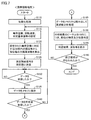
- FIG. 7 is a flowchart showing an example of the processing procedure in the mobile information terminal 30.
- the central processing unit 214 executes a predetermined initialization process (step S110).
- the initialization process for example, communication establishment between the communication unit 204 and the measuring instrument 20 and a predetermined reset process are performed.
- the setting unit 202 determines the vibration state based on the bearing model number of the rolling bearing 15 to be measured, the rotation speed (or rotation frequency) at the time of measurement, and the measurement data.
- the determination reference value and the like are set (step S115). Each of the above setting values is input by the user from the screen of the mobile information terminal 30.
- the central processing unit 214 reads out the specification data of the bearing corresponding to the set bearing model number from the DB unit 208, and from the specification data and the rotation frequency calculated from the set rotation speed, the above Using the formulas (1) to (3), the BPFI, BPFO, and BSF of the rolling bearing 15 to be measured are calculated (step S120). After that, the central processing unit 214 transmits a measurement start signal to the measuring instrument 20 through the communication unit 204 (step S125).
- the central processing unit 214 determines whether or not the measurement data (acceleration data) has been received from the measuring instrument 20 (step S130). Then, when the measurement data is received from the measuring instrument 20 (YES in step S130), the central processing unit 214 stores the received measurement data in a memory (not shown) (step S135).
- the central processing unit 214 determines whether or not the measurement data received from the measuring instrument 20 has reached a predetermined number (step S140), and if the data has not reached the predetermined number (NO in step S140), the step. The processing of S130 and S135 is repeated.
- step S140 When it is determined in step S140 that the number of data has reached a predetermined number (YES in step S140), the central processing unit 214 reads the data from the memory, and the data measured by the analysis unit 206 and the measuring instrument 20 (acceleration). Data) frequency analysis is performed (step S145). Specifically, a fast Fourier transform (FFT) process is performed on the time-series acceleration data measured by the measuring instrument 20, and the frequency spectrum of the measured acceleration data is obtained.
- FFT fast Fourier transform
- the central processing unit 214 extracts the top 10 peak values of the peaks in the obtained frequency spectrum, and identifies the parts corresponding to the peak frequencies of the extracted top 10 peaks. Specifically, the central processing unit 214 determines whether the peak frequency of each of the extracted peaks matches any of BPFI, BPFO, BSF, and their higher-order components, or the rotation frequency of the shaft. Whether the peak is due to an inner ring, an outer ring, a rolling element, an unbalanced shaft, a misalignment, or the like is identified by the frequency of the double frequency and which of the higher-order components thereof is matched. Then, the central processing unit 214 determines the vibration state of each of the specified parts based on the determination reference value set by the determination unit 210 (step S150).
- the determination unit 210 determines that a peak whose peak value exceeds the determination reference value is “dangerous”. Further, the determination unit 210 determines that a peak whose peak value is lower than the determination reference value but exceeds 80% of the determination reference value is "caution”, and a peak whose peak value is lower than 80% of the determination reference value. Judged as "good”.
- the central processing unit 214 uses the display unit 212 to display the determination result, peak value, peak frequency, and portion of step S150 for each of the top 10 peaks of the peak value, together with the waveform of the frequency spectrum of the portable information terminal 30. Display on the screen (step S155).
- the central processing unit 214 determines whether or not the end operation for ending the measurement has been performed by the user (step S160). When it is determined that the end operation has not been performed (NO in step S160), the process is returned to step S115. On the other hand, when it is determined that the end operation has been performed (YES in step S160), the process shifts to the end, and a series of processes in the mobile information terminal 30 are completed.
- the determination results (“danger”, “caution”, and “caution”) of the peak value (acceleration), peak frequency, and vibration state are obtained for the top 10 peaks of the peak value in the frequency spectrum of the measurement data. "Good” etc.), the part (damaged part), etc. are displayed on the screen of the mobile information terminal 30. As a result, the user can easily grasp the magnitude, the portion, and the vibration state of the portion for the peak having a large vibration.
- the number of displayed peaks can be set by the user, so that the display can be realized according to the user's wishes. Further, since the measuring instrument 20 and the mobile information terminal 30 communicate wirelessly, the user can vibrate anywhere within the range where wireless communication is possible as long as the measuring instrument 20 is installed as the measurement target. The analysis result can be confirmed.
- the judgment reference value for judging the vibration state (“danger”, “caution”, “good”, etc.) is set uniformly regardless of the frequency, but in the second embodiment, the judgment reference value is set uniformly.
- Judgment reference value is set for each frequency band. Thereby, the diagnosis is performed for each set frequency band based on an appropriate determination reference value, and it is possible to provide the diagnosis for the frequency band that the user wants to watch.
- the overall configuration of the vibration measurement system according to the second embodiment is the same as that of the first embodiment shown in FIGS. 1 to 3.
- FIG. 8 is a diagram showing an example of the determination reference value in the second embodiment.
- the horizontal axis represents frequency and the vertical axis represents acceleration (vibration).
- the waveform is an example of the result of frequency analysis performed by analysis unit 206.
- 10 frequency bands are set with a constant width from 0, and a judgment reference value is set for each frequency band, but the number of frequency bands is not limited to 10, and each frequency band is not limited to 10.
- the width of the frequency band does not necessarily have to be constant.
- the method for determining the frequency band ⁇ fi may be, for example, to set the width and number of frequency bands with the width of each frequency band constant, or to set the upper limit of the frequency to be analyzed with the number of frequency bands constant. You may set it.
- FIG. 9 is a diagram showing an example of information set by the setting unit 202 in the second embodiment. Also in the second embodiment, the information set by the setting unit 202 can be input by the user from the screen of the mobile information terminal 30, and in FIG. 9, the mobile information terminal 30 for the user to input the information is shown. Screen is shown.
- the bearing model number of the rolling bearing 15 (FIG. 1) to be measured can be input from the input unit 410.
- the rotation speed (min -1 ) of the shaft at the time of measurement can be input.
- the input unit 420 may input the rotation frequency of the shaft at the time of measurement instead of the rotation speed of the shaft at the time of measurement.
- the width of each frequency band can be input when the width of each frequency band is constant for the determination of the vibration state performed based on the judgment reference value set for each frequency band. .. Further, from the input unit 440, when the number of frequency bands is constant, the upper limit of the frequency to be analyzed can be input.
- the user may input either one of the input units 430 and 440, and if there is an input from both the input units 430 and 440, a predetermined value of one (for example, the input unit 430) is adopted. Will be done.
- the number of frequency bands can be input from the input unit 450.
- the frequency bandwidth is set by the input from the input unit 430
- the number of frequency bands having the frequency bandwidth is set by the number input from the input unit 450.
- the upper limit frequency is set by the input from the input unit 440
- the frequency band of the number input from the input unit 450 is set by dividing the upper limit frequency by the number input from the input unit 450. Will be done.
- a judgment reference value can be set for each frequency band.
- the input unit 460 displays each frequency band set from the frequency bandwidth input from the input unit 430 or the upper limit frequency input from the input unit 440 and the number of frequency bands input from the input unit 450. , Judgment reference value is shown for each frequency band.
- the determination reference value shown in the input unit 460 can be moved up and down using an input device (mouse, touch panel, etc.). The user can set the determination reference value for each frequency band in the input unit 460 using the input device.
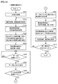
- FIG. 10 is a flowchart showing an example of the processing procedure in the mobile information terminal 30 of the second embodiment. Also in the second embodiment with reference to FIG. 10 and FIG. 3, application software for performing vibration measurement using the measuring instrument 20 is started on the mobile information terminal 30, and the application software instructs the start of measurement. Then, the central processing unit 214 executes a predetermined initialization process (step S210). This initialization process is the same as the process executed in step S110 of FIG.
- the setting unit 202 sets the bearing model number of the rolling bearing 15 to be measured, the rotation speed (or rotation frequency) at the time of measurement, and the like (step S215). These set values are input by the user from the screen of the mobile information terminal 30.
- the setting unit 202 sets the determination reference value for each frequency band (step S220). As described with reference to FIG. 9, each frequency band is set based on the input values from the input units 430 to 450, and the determination reference value for each frequency band is set based on the input from the input unit 460.
- step S220 When the determination reference value is set for each frequency band in step S220, the process shifts to step S225. Since the processes of steps S225 to S250 are the same as the processes of steps S120 to S145 of FIG. 7, the description will not be repeated.
- the central processing unit 214 sets the determination reference value for each frequency band set in step S220 by the determination unit 210. Based on this, the vibration state of the rolling bearing 15 for each frequency band is determined (step S255).
- the central processing unit 214 identifies a portion corresponding to the peak with respect to the peak whose peak value exceeds the determination reference value (step S260). Specifically, the central processing unit 214 determines whether the peak frequency matches any of BPFI, BPFO, BSF, and their higher-order components for each peak whose peak value exceeds the determination reference value, or the axis. Depending on whether it matches the rotation frequency, twice the frequency, or those higher-order components, which of the defects such as inner ring, outer ring, rolling element, shaft imbalance, and misalignment is the cause of the peak is determined. Identify.
- the central processing unit 214 uses the display unit 212 to display the determination result, peak value, peak frequency, and portion of step S255 for each peak whose peak value exceeds the determination reference value, together with the waveform of the frequency spectrum, of the mobile information terminal 30. Is displayed on the screen of (step S265).
- the central processing unit 214 determines whether or not the end operation for ending the measurement has been performed by the user (step S270). When it is determined that the end operation has not been performed (NO in step S270), the process is returned to step S215. On the other hand, when it is determined that the end operation has been performed (YES in step S270), the process shifts to the end, and a series of processes in the mobile information terminal 30 are completed.
- the determination reference value is set for each frequency band, and the vibration state is determined based on the peak value and the determination reference value of the frequency spectrum in each frequency band.
- the diagnosis is performed based on an appropriate determination reference value for each set frequency band, not for a specific frequency component caused by a bearing abnormality (inner ring, outer ring, rolling element, defect of cage). Therefore, according to the second embodiment, it is possible to provide a diagnostic result for a frequency band that the user wants to pay attention to.
- the measuring instrument 20 and the mobile information terminal 30 are wirelessly communicated with each other, the user can perform wireless communication as long as the measuring instrument 20 is installed as the measurement target. The vibration analysis result can be confirmed regardless of the location within the range.
- the damage frequency for specifying the damaged portion of the bearings is calculated by a predetermined calculation formula using the specification data of the bearings.
- Data regarding the coefficient of the rotation frequency of the bearing (a plurality of constants obtained by dividing the coefficient) is associated with the bearing model number and stored in the DB unit 208. Then, the data corresponding to the bearing model number set by the setting unit 202 is read from the DB unit 208, the damage frequency is calculated based on the read data, and the damaged part is specified.
- the DB unit 208 is the BPFI (Ball Pass Frequency of Inner ring, inner ring passing frequency) and BPFO (Ball Pass Frequency of Outer ring) of the rolling bearing 15 to be measured. , Outer ring passing frequency), and BSF (Ball Spin Frequency, rolling element rotation frequency) are stored in association with the bearing model number.
- the damaged part is specified in the mobile information terminal 30 without using a server. Therefore, it is necessary for the mobile information terminal 30 to have the coefficient of the rotation frequency of the bearing for calculating the BPFI, BPFO, and BSF of the rolling bearing 15 to be measured.
- the BPFI, BPFO, and BSF of the rolling bearing 15 can be calculated using the following equations (7) to (9) from various specifications of the rolling bearing 15 and the rotation frequency f0 of the inner ring shaft of the bearing at the time of measurement. it can.
- D is the pitch circle diameter of the bearing
- d is the diameter of the rolling element
- ⁇ is the contact angle of the rolling element
- Z is the number of rolling elements, and each value corresponds to the specifications of the rolling bearing 15. is there.
- the rotation frequency f0 corresponds to the measurement condition, and is set by the setting unit 202, or is calculated from the set rotation speed when the rotation speed is set by the setting unit 202.
- the coefficients Cin, Cout, and Crol of the rotation frequency f0 are calculated from the specifications of the rolling bearing 15 (bearing pitch circle diameter D, rolling element diameter d, rolling element contact angle ⁇ , number of rolling elements Z).
- the specification data of the rolling bearing 15 (bearing pitch circle diameter D, rolling element diameter d, rolling element contact angle ⁇ , rolling element). It is necessary for the mobile information terminal 30 to have the above coefficients Cin, Cout, and Crol calculated from the number Z) or the specification data.
- each of the coefficients Cin, Cout, and Croll is divided into a plurality of constants and stored in the DB unit 208 of the mobile information terminal 30.
- the coefficients Cin, Cout, and Crol are divided into the constants Ca to Cd represented by the following equations (10) to (12) and stored in the DB unit 208.
- the central processing unit 214 calculates the BPFI, BPFO, and BSF of the rolling bearing 15 at the time of measurement based on the information about the rolling bearing 15 set by the setting unit 202. Specifically, the central processing unit 214 reads out a plurality of constants Ca to Cd corresponding to the bearing model numbers set by the setting unit 202 from the DB unit 208, and the above equation is obtained from the read-out plurality of constants Ca to Cd. The coefficients Cin, Cout, and Crol are restored by (10) to (12). Then, the central processing unit 214 uses the above equations (7) to (9) from the restored coefficients Cin, Cout, and Crol and the rotation speed (or rotation frequency) set by the setting unit 202, and BPFI. , BPFO, BSF are calculated.
- the display unit 212 displays the peak value, the portion, and the determination result (“danger”, “caution”, “good”, etc.) of the determination unit 210 for the peak for which the portion is specified. Display on 30 screens.
- FIG. 11 is a diagram showing an example of information set by the setting unit 202 in the third embodiment.
- the information set by the setting unit 202 can be input by the user from the screen of the mobile information terminal 30, and FIG. 11 shows the screen of the mobile information terminal 30 for the user to input the information. ..
- the bearing model number of the rolling bearing 15 (FIG. 1) to be measured can be input from the input unit 310.
- the rotation speed (min -1 ) of the shaft at the time of measurement can be input. Since the vibration measurement system 10 is not provided with a sensor for detecting the rotation speed of the shaft during measurement by the measuring device 20, it is necessary to obtain information on the rotation speed and input it from the input unit 320 at the time of measurement. However, when the rotation speed sensor is attached, the input unit 320 is unnecessary. Further, the input unit 320 may input the rotation frequency of the shaft at the time of measurement instead of the rotation speed of the shaft at the time of measurement.
- the determination reference value (acceleration) used in the determination unit 210 can be input. Also in the third embodiment, the determination reference value is a uniform value regardless of the peak frequency.
- FIG. 12 is a diagram showing an example of data stored in the DB unit 208 in the third embodiment.
- a plurality of constants Ca to which the coefficients Cin, Cout, and Col for calculating the BPFI, BPFO, and BSF are divided for each bearing whose vibration can be measured by the vibration measurement system 10 Cd is stored according to the bearing model number.
- constants Ca to Cd even if the bearing leaks to the outside of the mobile information terminal 30, it is possible to prevent the specifications of the bearing from being elucidated.
- FIG. 13 is a flowchart showing an example of the processing procedure in the mobile information terminal 30.
- the central processing unit 214 executes a predetermined initialization process (step S310).
- the initialization process for example, communication establishment between the communication unit 204 and the measuring instrument 20 and a predetermined reset process are performed.
- the setting unit 202 determines the vibration state based on the bearing model number of the rolling bearing 15 to be measured, the rotation speed (or rotation frequency) at the time of measurement, and the measurement data.
- the determination reference value and the like are set (step S315). Each of the above setting values is input by the user from the screen of the mobile information terminal 30.
- the central processing unit 214 reads out the bearing constants Ca to Cd (division constants) corresponding to the set bearing model numbers from the DB unit 208, and from the read constants Ca to Cd, the above equations (10) to (10) to ( The coefficients Cin, Cout, and Crol are restored by 12) (step S320).
- the central processing unit 214 uses the above equations (7) to (9) from the restored coefficients Cin, Cout, and Col and the rotation frequency calculated from the rotation speed set in step S315.
- the BPFI, BPFO, and BSF of the rolling bearing 15 to be measured are calculated (step S322).
- the central processing unit 214 transmits a measurement start signal to the measuring instrument 20 through the communication unit 204 (step S325).
- the central processing unit 214 determines whether or not the measurement data (acceleration data) has been received from the measuring instrument 20 (step S330). Then, when the measurement data is received from the measuring instrument 20 (YES in step S330), the central processing unit 214 stores the received measurement data in a memory (not shown) (step S335).
- the central processing unit 214 determines whether or not the measurement data received from the measuring instrument 20 has reached a predetermined number (step S340), and if the data has not reached the predetermined number (NO in step S340), the step. The processing of S330 and S335 is repeated.
- step S340 When it is determined in step S340 that the number of data has reached a predetermined number (YES in step S340), the central processing unit 214 reads the data from the memory, and the data measured by the analysis unit 206 and the measuring instrument 20 (acceleration). Data) frequency analysis is performed (step S345). Specifically, a fast Fourier transform (FFT) process is performed on the time-series acceleration data measured by the measuring instrument 20, and the frequency spectrum of the measured acceleration data is obtained.
- FFT fast Fourier transform
- the central processing unit 214 indicates that the peak frequency of the peak in the obtained frequency spectrum matches any of BPFI, BPFO, BSF, and higher-order components thereof, or the rotation frequency of the axis, which is twice that. Whether the peak is due to defects such as inner ring, outer ring, rolling element, shaft imbalance, misalignment, etc. is identified by the frequency of the frequency and which of these higher-order components is matched. Then, the central processing unit 214 determines the vibration state of each of the specified parts by the determination unit 210 based on the judgment reference value set in step S315 (step S350).
- the determination unit 210 determines that a peak whose peak value exceeds the determination reference value is “dangerous”. Further, the determination unit 210 determines that a peak whose peak value is lower than the determination reference value but exceeds 80% of the determination reference value is "caution”, and a peak whose peak value is lower than 80% of the determination reference value. Judged as "good”.
- the central processing unit 214 displays the determination result, peak value, peak frequency, and portion of step S350 on the screen of the mobile information terminal 30 together with the waveform of the frequency spectrum by the display unit 212 (step S355).
- the central processing unit 214 determines whether or not the end operation for ending the measurement has been performed by the user (step S360). When it is determined that the end operation has not been performed (NO in step S360), the process is returned to step S315. On the other hand, when it is determined that the end operation has been performed (YES in step S360), the process shifts to the end, and a series of processes in the mobile information terminal 30 are completed.
- the coefficients Cin, Cout, and Crol for calculating the BPFI, BPFO, and BSF are divided into a plurality of constants Ca to Cd and stored in the DB unit 208. Then, when the vibration analysis is executed, the constants Ca to Cd are read from the DB unit 208, the coefficients Cin, Cout, and Crol are restored, and the restored coefficients Cin, Cout, and Crol are used to calculate BPFI, BPFO, and BSF. Will be done.
- the data (constants Ca to Cd) stored in the DB unit 208 leaks to the outside of the mobile information terminal 30, the specifications of the bearing that can be measured by the vibration measurement system 10 will be clarified. Can be prevented. Therefore, according to the third embodiment, it is possible to prevent leakage of bearing specification data.
- the measuring instrument 20 and the mobile information terminal 30 are wirelessly communicated with each other, the user can perform wireless communication as long as the measuring instrument 20 is installed as the measurement target. The vibration analysis result can be confirmed regardless of the location within the range.
- each of the coefficients Cin, Cout, and Crol used for calculating the BPFI, BPFO, and BSF is divided into a plurality of constants Ca to Cd and stored in the DB unit 208.
- the specification data of the rolling bearing 15 to be measured (bearing pitch circle diameter D, rolling element diameter d, rolling element contact angle ⁇ , number of rolling elements Z, etc.) are encrypted and the DB unit is used.
- the encrypted specification data is read from the DB unit 208 and decrypted, and BPFI, BPFO, and BSF are calculated.
- the overall configuration of the vibration measurement system according to the fourth embodiment is the same as that of the first embodiment shown in FIGS. 1 and 2.
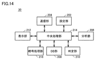
- FIG. 14 is a diagram showing the configuration of the mobile information terminal 30 according to the fourth embodiment.
- the mobile information terminal 30 according to the fourth embodiment further includes an encryption processing unit 216 in the mobile information terminal 30 according to the first embodiment shown in FIG.
- the specification data encrypted according to a predetermined encryption method is stored in the DB unit 208 in association with the bearing model number for various bearings whose vibration can be measured by the vibration measurement system 10.
- the encryption method may be a common key cryptosystem or a public key cryptosystem. Further, the encryption may be performed using the same key encryption for each specification, or may be performed using a different key encryption for each specification. Various known methods can be used as the encryption method.
- the encryption processing unit 216 reads the specification data (encrypted data) corresponding to the bearing model number set by the setting unit 202 from the DB unit 208 according to the instruction from the central processing unit 214, and performs the key encryption according to the encryption method. It is used to decode the read specification data.
- the central processing unit 214 uses the above equations (7) to (9) from the specification data decrypted by the encryption processing unit 216 and the rotation speed (or rotation frequency) set by the setting unit 202, and BPFI. , BPFO, BSF are calculated.
- the processing of the central processing unit 214 after calculating the BPFI, BPFO, and BSF is the same as that of the third embodiment.
- FIG. 15 is a flowchart showing an example of the processing procedure in the mobile information terminal 30 of the fourth embodiment.
- application software for performing vibration measurement using the measuring instrument 20 is started on the mobile information terminal 30, and the application software instructs the start of measurement.
- the central processing unit 214 executes a predetermined initialization process (step S410).
- the setting unit 202 sets the bearing model number of the rolling bearing 15 to be measured, the rotation speed (or rotation frequency) at the time of measurement, the determination reference value for determining the vibration state based on the measurement data, and the like ( Step S415).
- the process executed in steps S410 and S415 is the same as the process executed in steps S310 and S315 of FIG.
- the specification data (encrypted data) of the bearing corresponding to the set bearing model number was read from the DB unit 208 and encrypted by the encryption processing unit 216 using a key encryption according to a predetermined encryption method.
- the specification data is decrypted (step S420).
- the central processing unit 214 uses the above equations (7) to (9) to measure the height from the decoded specification data and the rotation frequency calculated from the rotation speed set in step S415.
- the BPFI, BPFO, and BSF of a certain rolling bearing 15 are calculated (step S422).
- step S422 When BPFI, BPFO, and BSF are calculated in step S422, the process shifts to step S425. Since the processes of steps S425 to S455 are the same as the processes of steps S325 to S355 of FIG. 13, the description will not be repeated.
- step S460 determines whether or not the end operation for ending the measurement has been performed by the user.
- the process is returned to step S415.
- the process shifts to the end, and a series of processes in the mobile information terminal 30 are completed.
- the specification data of the rolling bearing 15 to be measured is encrypted and stored in the DB unit 208. Then, when the vibration analysis is executed, the encrypted specification data is read from the DB unit 208 and decoded, and the BPFI, BPFO, and BSF are calculated using the decoded specification data. As a result, if the data (encrypted specification data) stored in the DB unit 208 leaks to the outside of the mobile information terminal 30, the specifications of the bearing that can be measured by the vibration measuring system 10 are clarified. Can be prevented. Therefore, even according to the fourth embodiment, leakage of bearing specification data can be prevented.
- the measuring instrument 20 and the mobile information terminal 30 are wirelessly communicated with each other, the user can perform wireless communication as long as the measuring instrument 20 is installed as the measurement target. The vibration analysis result can be confirmed regardless of the location within the range.
- the specification data to be measured is encrypted and stored in the DB unit 208, but the coefficients Cin, Cout, and Crol for calculating the BPFI, BPFO, and BSF are assumed. May be encrypted and stored in the DB unit 208, or a plurality of constants Ca to Cd obtained by dividing the coefficients Cin, Cout, and Crol described in the third embodiment may be encrypted and stored in the DB unit 208. Good.
- a plurality of constants Ca to Cd may be stored in the DB unit 208 in a binary format. This also makes it possible to prevent the specifications of the bearings measurable by the vibration measuring system 10 from being clarified if the data stored in the DB unit 208 leaks to the outside of the mobile information terminal 30.
- the specification data in the binary format may be encrypted and stored in the DB unit 208.
- the coefficients Cin, Cout, Crol in the binary format, or a plurality of constants Ca to Cd in the binary format may be encrypted and stored in the DB unit 208.
- the measuring instrument 20 and the mobile information terminal 30 are wirelessly communicated with each other.
- the measuring instrument 20 and the mobile information terminal 30 are connected to each other. It may be connected by the communication line 40 and communicate between the measuring instrument 20 and the mobile information terminal 30 through the communication line 40.
- Vibration measurement system 15 Measurement target (rolling bearing), 20 Measuring instrument, 30 Mobile information terminal, 40 Communication line, 102 Accelerometer, 104 Anti-aliasing filter, 106 A / D converter, 108 Microcomputer, 110 Memory, 112 Communication module, 202 setting unit, 204 communication unit, 206 analysis unit, 208 DB unit, 210 judgment unit, 212 display unit, 214 central processing unit, 216 encryption processing unit, 310 to 340, 410 to 460 input unit.
Landscapes
- Physics & Mathematics (AREA)
- General Physics & Mathematics (AREA)
- Acoustics & Sound (AREA)
- Engineering & Computer Science (AREA)
- Computer Networks & Wireless Communication (AREA)
- Measurement Of Mechanical Vibrations Or Ultrasonic Waves (AREA)
- Testing Of Devices, Machine Parts, Or Other Structures Thereof (AREA)
Abstract
L'invention concerne une unité centrale de traitement (214) qui localise, en fonction d'informations relatives à un roulement soumis à une mesure, des régions de crête présentant les 10 valeurs de crête les plus élevées dans un spectre de fréquence obtenu par analyse de fréquence. Une unité de détermination (210) détermine des états de vibration par rapport aux crêtes présentant les 10 valeurs de crête les plus élevées en fonction des valeurs de crête et d'une valeur de référence de détermination. Une unité d'affichage (212) affiche une valeur de crête, une région, et un résultat de détermination fourni par l'unité de détermination (210) par rapport à chacune des crêtes présentant les 10 valeurs de crête les plus élevées.
Priority Applications (3)
| Application Number | Priority Date | Filing Date | Title |
|---|---|---|---|
| EP20871415.4A EP4043856B1 (fr) | 2019-10-02 | 2020-09-24 | Dispositif d'analyse de vibrations et système de mesure de vibrations |
| US17/765,350 US20220397484A1 (en) | 2019-10-02 | 2020-09-24 | Vibration analysis apparatus and vibration measurement system |
| CN202080083260.3A CN114829895A (zh) | 2019-10-02 | 2020-09-24 | 振动分析装置和振动测量系统 |
Applications Claiming Priority (4)
| Application Number | Priority Date | Filing Date | Title |
|---|---|---|---|
| JP2019-181804 | 2019-10-02 | ||
| JP2019181804A JP7443011B2 (ja) | 2019-10-02 | 2019-10-02 | 振動解析装置及び振動測定システム |
| JP2019184541A JP7360887B2 (ja) | 2019-10-07 | 2019-10-07 | 振動解析装置及び振動測定システム |
| JP2019-184541 | 2019-10-07 |
Publications (1)
| Publication Number | Publication Date |
|---|---|
| WO2021065663A1 true WO2021065663A1 (fr) | 2021-04-08 |
Family
ID=75337155
Family Applications (1)
| Application Number | Title | Priority Date | Filing Date |
|---|---|---|---|
| PCT/JP2020/035984 Ceased WO2021065663A1 (fr) | 2019-10-02 | 2020-09-24 | Dispositif d'analyse de vibrations et système de mesure de vibrations |
Country Status (4)
| Country | Link |
|---|---|
| US (1) | US20220397484A1 (fr) |
| EP (1) | EP4043856B1 (fr) |
| CN (1) | CN114829895A (fr) |
| WO (1) | WO2021065663A1 (fr) |
Cited By (1)
| Publication number | Priority date | Publication date | Assignee | Title |
|---|---|---|---|---|
| WO2024004253A1 (fr) * | 2022-06-27 | 2024-01-04 | 東芝インフラシステムズ株式会社 | Dispositif de détermination de son anormal |
Families Citing this family (1)
| Publication number | Priority date | Publication date | Assignee | Title |
|---|---|---|---|---|
| JP7710303B2 (ja) * | 2021-02-08 | 2025-07-18 | Ntn株式会社 | 振動分析装置および振動分析システム |
Citations (8)
| Publication number | Priority date | Publication date | Assignee | Title |
|---|---|---|---|---|
| JPS6293620A (ja) * | 1985-10-18 | 1987-04-30 | Kawasaki Steel Corp | 回転機診断器 |
| JPH10221160A (ja) * | 1997-02-05 | 1998-08-21 | Toshiba Corp | 回転機、回転機設備、輸送システム、加振構造物等の健全性確認検査装置および方法 |
| JP2005233789A (ja) * | 2004-02-19 | 2005-09-02 | Nsk Ltd | 回転機械の異常診断方法、異常診断装置および異常診断システム |
| WO2006043511A1 (fr) * | 2004-10-18 | 2006-04-27 | Nsk Ltd. | Systeme de diagnostic d’anomalie pour une machinerie |
| JP2006302293A (ja) * | 2005-04-21 | 2006-11-02 | General Electric Co <Ge> | 機械を診断するための方法およびシステム |
| JP2007278894A (ja) * | 2006-04-07 | 2007-10-25 | Nsk Ltd | 異常診断装置および異常診断方法 |
| US7587299B2 (en) | 2000-11-06 | 2009-09-08 | Nsk Ltd. | Anomaly diagnosis apparatus and method of machine installation |
| JP2016024007A (ja) | 2014-07-18 | 2016-02-08 | Ntn株式会社 | 機械部品診断システムおよびそのサーバ |
Family Cites Families (9)
| Publication number | Priority date | Publication date | Assignee | Title |
|---|---|---|---|---|
| US6321602B1 (en) * | 1999-09-28 | 2001-11-27 | Rockwell Science Center, Llc | Condition based monitoring by vibrational analysis |
| JP4818594B2 (ja) * | 2004-07-30 | 2011-11-16 | 住友重機械エンバイロメント株式会社 | 有機酸生成方法、有機酸生成装置及び排水処理装置 |
| WO2006030786A1 (fr) * | 2004-09-13 | 2006-03-23 | Nsk Ltd. | Dispositif de diagnostic d’anomalie et procede de diagnostic d’anomalie |
| JP2006113002A (ja) * | 2004-10-18 | 2006-04-27 | Nsk Ltd | 機械設備の異常診断システム |
| KR100874870B1 (ko) * | 2007-08-09 | 2008-12-19 | 울산대학교 산학협력단 | 영역분할기법을 이용한 피크 코드의 부여방법과 그 피크코드 및 그 피크 코드를 이용한 기계장치의 고장예측진단방법 |
| EP2543977B8 (fr) * | 2010-03-03 | 2019-06-26 | Asahi Kasei Engineering Corporation | Procédé de diagnostic et dispositif de diagnostic pour un palier lisse |
| GB2543521A (en) * | 2015-10-20 | 2017-04-26 | Skf Ab | Method and data processing device for severity assessment of bearing defects using vibration energy |
| US11506569B2 (en) * | 2019-01-15 | 2022-11-22 | Computational Systems, Inc. | Bearing and fault frequency identification from vibration spectral plots |
| CN110160767B (zh) * | 2019-06-14 | 2021-03-02 | 安徽智寰科技有限公司 | 基于包络分析的冲击周期自动识别与提取方法及系统 |
-
2020
- 2020-09-24 WO PCT/JP2020/035984 patent/WO2021065663A1/fr not_active Ceased
- 2020-09-24 EP EP20871415.4A patent/EP4043856B1/fr active Active
- 2020-09-24 US US17/765,350 patent/US20220397484A1/en not_active Abandoned
- 2020-09-24 CN CN202080083260.3A patent/CN114829895A/zh active Pending
Patent Citations (8)
| Publication number | Priority date | Publication date | Assignee | Title |
|---|---|---|---|---|
| JPS6293620A (ja) * | 1985-10-18 | 1987-04-30 | Kawasaki Steel Corp | 回転機診断器 |
| JPH10221160A (ja) * | 1997-02-05 | 1998-08-21 | Toshiba Corp | 回転機、回転機設備、輸送システム、加振構造物等の健全性確認検査装置および方法 |
| US7587299B2 (en) | 2000-11-06 | 2009-09-08 | Nsk Ltd. | Anomaly diagnosis apparatus and method of machine installation |
| JP2005233789A (ja) * | 2004-02-19 | 2005-09-02 | Nsk Ltd | 回転機械の異常診断方法、異常診断装置および異常診断システム |
| WO2006043511A1 (fr) * | 2004-10-18 | 2006-04-27 | Nsk Ltd. | Systeme de diagnostic d’anomalie pour une machinerie |
| JP2006302293A (ja) * | 2005-04-21 | 2006-11-02 | General Electric Co <Ge> | 機械を診断するための方法およびシステム |
| JP2007278894A (ja) * | 2006-04-07 | 2007-10-25 | Nsk Ltd | 異常診断装置および異常診断方法 |
| JP2016024007A (ja) | 2014-07-18 | 2016-02-08 | Ntn株式会社 | 機械部品診断システムおよびそのサーバ |
Non-Patent Citations (1)
| Title |
|---|
| See also references of EP4043856A4 |
Cited By (2)
| Publication number | Priority date | Publication date | Assignee | Title |
|---|---|---|---|---|
| WO2024004253A1 (fr) * | 2022-06-27 | 2024-01-04 | 東芝インフラシステムズ株式会社 | Dispositif de détermination de son anormal |
| JP7434671B1 (ja) * | 2022-06-27 | 2024-02-20 | 東芝インフラシステムズ株式会社 | 異音判定装置 |
Also Published As
| Publication number | Publication date |
|---|---|
| EP4043856B1 (fr) | 2024-08-07 |
| US20220397484A1 (en) | 2022-12-15 |
| EP4043856A1 (fr) | 2022-08-17 |
| CN114829895A (zh) | 2022-07-29 |
| EP4043856A4 (fr) | 2023-10-11 |
Similar Documents
| Publication | Publication Date | Title |
|---|---|---|
| JP5293300B2 (ja) | 回転機の振動監視装置および振動監視方法 | |
| CN110431390B (zh) | 信息终端器和机械部件诊断系统 | |
| JP2008292288A (ja) | 減速機の軸受診断装置 | |
| EP3842780B1 (fr) | Procédé et dispositif de diagnostic d'une anomalie au sein d'un palier à roulement | |
| JP2020183939A (ja) | ギアボックスの異常検出方法及び情報処理装置 | |
| JP7360887B2 (ja) | 振動解析装置及び振動測定システム | |
| EP4336164B1 (fr) | Dispositif de diagnostic de vibrations | |
| WO2021065663A1 (fr) | Dispositif d'analyse de vibrations et système de mesure de vibrations | |
| CN105829857A (zh) | 旋转机械部件的利用便携终端的检查系统和检查方法 | |
| JP2019045472A (ja) | 状態監視装置および状態監視方法 | |
| CN109556895A (zh) | 旋转机械的故障分析方法及装置 | |
| WO2018190216A1 (fr) | Dispositif de surveillance d'état, système de surveillance d'état et procédé de surveillance d'état | |
| JP2011191181A (ja) | 回転機器の異常診断システム、回転機器の異常診断装置及び回転機器の異常診断方法 | |
| JP5218614B2 (ja) | 異常診断装置、回転装置、鉄道車両、自動車及び異常診断方法 | |
| WO2022168918A1 (fr) | Dispositif d'analyse de vibrations et système d'analyse de vibration | |
| JP2016170085A (ja) | 異常診断装置及び異常診断方法 | |
| JP6897064B2 (ja) | 軸受異常診断方法および診断システム | |
| JP6869156B2 (ja) | 状態監視装置および状態監視方法 | |
| JP7040920B2 (ja) | 軸受の状態監視装置及び異常診断方法 | |
| JP7443011B2 (ja) | 振動解析装置及び振動測定システム | |
| JP4997936B2 (ja) | 転がり軸受の異常診断装置および乗物 | |
| JP5321646B2 (ja) | 異常検査方法及び異常検査装置 | |
| CN102788014B (zh) | 齿轮油泵齿面磨损故障诊断装置及方法 | |
| JP2000162035A (ja) | 回転機器の異常判定方法及びその装置 | |
| KR101504344B1 (ko) | 회전수 측정 알고리즘, 회전수 측정 장치, 및 회전수 측정 방법 |
Legal Events
| Date | Code | Title | Description |
|---|---|---|---|
| 121 | Ep: the epo has been informed by wipo that ep was designated in this application |
Ref document number: 20871415 Country of ref document: EP Kind code of ref document: A1 |
|
| NENP | Non-entry into the national phase |
Ref country code: DE |
|
| ENP | Entry into the national phase |
Ref document number: 2020871415 Country of ref document: EP Effective date: 20220502 |