EP4044264A1 - Weisslichtquelle und weisslichtquellensystem damit - Google Patents
Weisslichtquelle und weisslichtquellensystem damit Download PDFInfo
- Publication number
- EP4044264A1 EP4044264A1 EP22152098.4A EP22152098A EP4044264A1 EP 4044264 A1 EP4044264 A1 EP 4044264A1 EP 22152098 A EP22152098 A EP 22152098A EP 4044264 A1 EP4044264 A1 EP 4044264A1
- Authority
- EP
- European Patent Office
- Prior art keywords
- white light
- light source
- phosphor
- white
- emission spectrum
- Prior art date
- Legal status (The legal status is an assumption and is not a legal conclusion. Google has not performed a legal analysis and makes no representation as to the accuracy of the status listed.)
- Granted
Links
Images


Classifications
-
- H—ELECTRICITY
- H10—SEMICONDUCTOR DEVICES; ELECTRIC SOLID-STATE DEVICES NOT OTHERWISE PROVIDED FOR
- H10H—INORGANIC LIGHT-EMITTING SEMICONDUCTOR DEVICES HAVING POTENTIAL BARRIERS
- H10H20/00—Individual inorganic light-emitting semiconductor devices having potential barriers, e.g. light-emitting diodes [LED]
- H10H20/80—Constructional details
- H10H20/85—Packages
- H10H20/851—Wavelength conversion means
-
- F—MECHANICAL ENGINEERING; LIGHTING; HEATING; WEAPONS; BLASTING
- F21—LIGHTING
- F21K—NON-ELECTRIC LIGHT SOURCES USING LUMINESCENCE; LIGHT SOURCES USING ELECTROCHEMILUMINESCENCE; LIGHT SOURCES USING CHARGES OF COMBUSTIBLE MATERIAL; LIGHT SOURCES USING SEMICONDUCTOR DEVICES AS LIGHT-GENERATING ELEMENTS; LIGHT SOURCES NOT OTHERWISE PROVIDED FOR
- F21K9/00—Light sources using semiconductor devices as light-generating elements, e.g. using light-emitting diodes [LED] or lasers
- F21K9/60—Optical arrangements integrated in the light source, e.g. for improving the colour rendering index or the light extraction
-
- C—CHEMISTRY; METALLURGY
- C09—DYES; PAINTS; POLISHES; NATURAL RESINS; ADHESIVES; COMPOSITIONS NOT OTHERWISE PROVIDED FOR; APPLICATIONS OF MATERIALS NOT OTHERWISE PROVIDED FOR
- C09K—MATERIALS FOR MISCELLANEOUS APPLICATIONS, NOT PROVIDED FOR ELSEWHERE
- C09K11/00—Luminescent materials, e.g. electroluminescent or chemiluminescent
- C09K11/08—Luminescent materials, e.g. electroluminescent or chemiluminescent containing inorganic luminescent materials
- C09K11/77—Luminescent materials, e.g. electroluminescent or chemiluminescent containing inorganic luminescent materials containing rare earth metals
- C09K11/7728—Luminescent materials, e.g. electroluminescent or chemiluminescent containing inorganic luminescent materials containing rare earth metals containing europium
- C09K11/7734—Aluminates
-
- C—CHEMISTRY; METALLURGY
- C09—DYES; PAINTS; POLISHES; NATURAL RESINS; ADHESIVES; COMPOSITIONS NOT OTHERWISE PROVIDED FOR; APPLICATIONS OF MATERIALS NOT OTHERWISE PROVIDED FOR
- C09K—MATERIALS FOR MISCELLANEOUS APPLICATIONS, NOT PROVIDED FOR ELSEWHERE
- C09K11/00—Luminescent materials, e.g. electroluminescent or chemiluminescent
- C09K11/08—Luminescent materials, e.g. electroluminescent or chemiluminescent containing inorganic luminescent materials
- C09K11/77—Luminescent materials, e.g. electroluminescent or chemiluminescent containing inorganic luminescent materials containing rare earth metals
- C09K11/7728—Luminescent materials, e.g. electroluminescent or chemiluminescent containing inorganic luminescent materials containing rare earth metals containing europium
- C09K11/77342—Silicates
-
- C—CHEMISTRY; METALLURGY
- C09—DYES; PAINTS; POLISHES; NATURAL RESINS; ADHESIVES; COMPOSITIONS NOT OTHERWISE PROVIDED FOR; APPLICATIONS OF MATERIALS NOT OTHERWISE PROVIDED FOR
- C09K—MATERIALS FOR MISCELLANEOUS APPLICATIONS, NOT PROVIDED FOR ELSEWHERE
- C09K11/00—Luminescent materials, e.g. electroluminescent or chemiluminescent
- C09K11/08—Luminescent materials, e.g. electroluminescent or chemiluminescent containing inorganic luminescent materials
- C09K11/77—Luminescent materials, e.g. electroluminescent or chemiluminescent containing inorganic luminescent materials containing rare earth metals
- C09K11/7728—Luminescent materials, e.g. electroluminescent or chemiluminescent containing inorganic luminescent materials containing rare earth metals containing europium
- C09K11/77348—Silicon Aluminium Nitrides or Silicon Aluminium Oxynitrides
-
- F—MECHANICAL ENGINEERING; LIGHTING; HEATING; WEAPONS; BLASTING
- F21—LIGHTING
- F21V—FUNCTIONAL FEATURES OR DETAILS OF LIGHTING DEVICES OR SYSTEMS THEREOF; STRUCTURAL COMBINATIONS OF LIGHTING DEVICES WITH OTHER ARTICLES, NOT OTHERWISE PROVIDED FOR
- F21V1/00—Shades for light sources, i.e. lampshades for table, floor, wall or ceiling lamps
- F21V1/14—Covers for frames; Frameless shades
- F21V1/16—Covers for frames; Frameless shades characterised by the material
- F21V1/17—Covers for frames; Frameless shades characterised by the material the material comprising photoluminescent substances
-
- F—MECHANICAL ENGINEERING; LIGHTING; HEATING; WEAPONS; BLASTING
- F21—LIGHTING
- F21V—FUNCTIONAL FEATURES OR DETAILS OF LIGHTING DEVICES OR SYSTEMS THEREOF; STRUCTURAL COMBINATIONS OF LIGHTING DEVICES WITH OTHER ARTICLES, NOT OTHERWISE PROVIDED FOR
- F21V3/00—Globes; Bowls; Cover glasses
- F21V3/04—Globes; Bowls; Cover glasses characterised by materials, surface treatments or coatings
- F21V3/10—Globes; Bowls; Cover glasses characterised by materials, surface treatments or coatings characterised by coatings
- F21V3/12—Globes; Bowls; Cover glasses characterised by materials, surface treatments or coatings characterised by coatings the coatings comprising photoluminescent substances
-
- F—MECHANICAL ENGINEERING; LIGHTING; HEATING; WEAPONS; BLASTING
- F21—LIGHTING
- F21V—FUNCTIONAL FEATURES OR DETAILS OF LIGHTING DEVICES OR SYSTEMS THEREOF; STRUCTURAL COMBINATIONS OF LIGHTING DEVICES WITH OTHER ARTICLES, NOT OTHERWISE PROVIDED FOR
- F21V9/00—Elements for modifying spectral properties, polarisation or intensity of the light emitted, e.g. filters
- F21V9/02—Elements for modifying spectral properties, polarisation or intensity of the light emitted, e.g. filters for simulating daylight
-
- F—MECHANICAL ENGINEERING; LIGHTING; HEATING; WEAPONS; BLASTING
- F21—LIGHTING
- F21V—FUNCTIONAL FEATURES OR DETAILS OF LIGHTING DEVICES OR SYSTEMS THEREOF; STRUCTURAL COMBINATIONS OF LIGHTING DEVICES WITH OTHER ARTICLES, NOT OTHERWISE PROVIDED FOR
- F21V9/00—Elements for modifying spectral properties, polarisation or intensity of the light emitted, e.g. filters
- F21V9/30—Elements containing photoluminescent material distinct from or spaced from the light source
-
- F—MECHANICAL ENGINEERING; LIGHTING; HEATING; WEAPONS; BLASTING
- F21—LIGHTING
- F21V—FUNCTIONAL FEATURES OR DETAILS OF LIGHTING DEVICES OR SYSTEMS THEREOF; STRUCTURAL COMBINATIONS OF LIGHTING DEVICES WITH OTHER ARTICLES, NOT OTHERWISE PROVIDED FOR
- F21V9/00—Elements for modifying spectral properties, polarisation or intensity of the light emitted, e.g. filters
- F21V9/30—Elements containing photoluminescent material distinct from or spaced from the light source
- F21V9/32—Elements containing photoluminescent material distinct from or spaced from the light source characterised by the arrangement of the photoluminescent material
-
- H—ELECTRICITY
- H10—SEMICONDUCTOR DEVICES; ELECTRIC SOLID-STATE DEVICES NOT OTHERWISE PROVIDED FOR
- H10H—INORGANIC LIGHT-EMITTING SEMICONDUCTOR DEVICES HAVING POTENTIAL BARRIERS
- H10H20/00—Individual inorganic light-emitting semiconductor devices having potential barriers, e.g. light-emitting diodes [LED]
- H10H20/80—Constructional details
- H10H20/85—Packages
- H10H20/851—Wavelength conversion means
- H10H20/8511—Wavelength conversion means characterised by their material, e.g. binder
- H10H20/8512—Wavelength conversion materials
- H10H20/8513—Wavelength conversion materials having two or more wavelength conversion materials
-
- F—MECHANICAL ENGINEERING; LIGHTING; HEATING; WEAPONS; BLASTING
- F21—LIGHTING
- F21Y—INDEXING SCHEME ASSOCIATED WITH SUBCLASSES F21K, F21L, F21S and F21V, RELATING TO THE FORM OR THE KIND OF THE LIGHT SOURCES OR OF THE COLOUR OF THE LIGHT EMITTED
- F21Y2113/00—Combination of light sources
- F21Y2113/10—Combination of light sources of different colours
- F21Y2113/13—Combination of light sources of different colours comprising an assembly of point-like light sources
-
- F—MECHANICAL ENGINEERING; LIGHTING; HEATING; WEAPONS; BLASTING
- F21—LIGHTING
- F21Y—INDEXING SCHEME ASSOCIATED WITH SUBCLASSES F21K, F21L, F21S and F21V, RELATING TO THE FORM OR THE KIND OF THE LIGHT SOURCES OR OF THE COLOUR OF THE LIGHT EMITTED
- F21Y2113/00—Combination of light sources
- F21Y2113/30—Combination of light sources of visible and non-visible spectrum
-
- F—MECHANICAL ENGINEERING; LIGHTING; HEATING; WEAPONS; BLASTING
- F21—LIGHTING
- F21Y—INDEXING SCHEME ASSOCIATED WITH SUBCLASSES F21K, F21L, F21S and F21V, RELATING TO THE FORM OR THE KIND OF THE LIGHT SOURCES OR OF THE COLOUR OF THE LIGHT EMITTED
- F21Y2115/00—Light-generating elements of semiconductor light sources
- F21Y2115/10—Light-emitting diodes [LED]
-
- H—ELECTRICITY
- H10—SEMICONDUCTOR DEVICES; ELECTRIC SOLID-STATE DEVICES NOT OTHERWISE PROVIDED FOR
- H10W—GENERIC PACKAGES, INTERCONNECTIONS, CONNECTORS OR OTHER CONSTRUCTIONAL DETAILS OF DEVICES COVERED BY CLASS H10
- H10W90/00—Package configurations
-
- Y—GENERAL TAGGING OF NEW TECHNOLOGICAL DEVELOPMENTS; GENERAL TAGGING OF CROSS-SECTIONAL TECHNOLOGIES SPANNING OVER SEVERAL SECTIONS OF THE IPC; TECHNICAL SUBJECTS COVERED BY FORMER USPC CROSS-REFERENCE ART COLLECTIONS [XRACs] AND DIGESTS
- Y02—TECHNOLOGIES OR APPLICATIONS FOR MITIGATION OR ADAPTATION AGAINST CLIMATE CHANGE
- Y02B—CLIMATE CHANGE MITIGATION TECHNOLOGIES RELATED TO BUILDINGS, e.g. HOUSING, HOUSE APPLIANCES OR RELATED END-USER APPLICATIONS
- Y02B20/00—Energy efficient lighting technologies, e.g. halogen lamps or gas discharge lamps
Definitions
- the present invention relates to a white light source and a white light source system including the white light source. More particularly, the present invention relates to a white light source having a light emission spectrum close to the light emission spectrum of natural light, and relates to a white light source system including the white light source.
- LEDs light emitting diodes
- LEDs have longer service life, and enable energy saving.
- Patent Document 1 Japanese Patent Laid-Open (Unexamined Publication) No. 10-242513
- Patent Document 1 in conventional white LEDs, YAG phosphors are excited using blue LEDs each having a light emission peak wavelength in a range of 400 to 530 nm, and the blue light emitted from the LEDs and the yellow light emitted from the YAG phosphors are mixed with each other, whereby white light is achieved and realized.
- White light sources including LEDs have been widely used as backlights of traffic signal lights and liquid crystal displays (LCD) as well as general lighting equipment (illuminating equipment) such as room lights.
- LCD liquid crystal displays
- general lighting equipment illumination equipment
- the peak height of the blue light emitted from the blue LEDs is as large as at least 1.5 times the peak height of the yellow light emitted from phosphors, and hence influences of the blue light tend to be strong.
- the white light sources including LEDs
- adverse effects of the white light sources on human bodies start to be concerned about.
- the light emission peaks of blue LEDs are strong in conventional white LEDs.
- Such white light having a strong blue emission peak is significantly different from that of natural light.
- the natural light refers to sunlight.
- Patent Document 2 According to the pamphlet of International Publication No. WO 2008/069101 (Patent Document 2), which has been achieved in consideration of the influences of such white light sources on human bodies, LEDs and phosphors having different light emission peaks are combined, and four types of light emission peak are thus mixed, whereby a white light with a small deviation from the spectral luminous efficiency is provided.
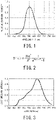
- FIG. 1 shows the spectral luminous efficiency V( ⁇ ) defined by CIE. That is, FIG. 1 shows that humans recognize light having a wavelength of about 555 nm at the highest sensitivity.
- Patent Document 2 has an object to control light having a wavelength in a range of 420 to 490 nm, in consideration of influences of blue light on human bodies. Such a method can be expected to produce an effect of normalizing the secretion of melatonin that is one of hormones concerning adjustment by a biological clock in the nighttime.
- humans have a circadian rhythm (24-hour rhythm) controlled by an internal body clock.
- Humans are supposed to basically live under natural light, but there are a variety of lifestyles, such as long-time indoor work and a day-night reversal style, in modern society. If a life without exposure to natural light is continued for a long period, the circadian rhythm is disturbed, and adverse effects on human bodies are concerned about.
- white light sources including LEDs that is, white light sources including blue LEDs have light emission spectra significantly different from that of natural light. A long-time life under irradiation by such white light sources may adversely affect a human circadian rhythm.
- the present invention which has been made in order to deal with such a problem, has an object to provide a white light source and a white light source system having a light emission spectrum close to the light emission spectrum of natural light.
- a white light source comprises: a blue light emitting diode (blue LED) having a light emission peak wavelength in a range of 421 to 490 nm; and a phosphor layer including phosphor and resin, wherein the white light source satisfies a relational equation of -0.2 ⁇ [(P( ⁇ ) ⁇ Y( ⁇ )) / (P( ⁇ max1) ⁇ V( ⁇ max1)) - (B( ⁇ ) ⁇ V( ⁇ )) / (B( ⁇ max2) ⁇ V( ⁇ max2))] ⁇ +0.2, assuming that: a light emission spectrum of the white light source is P( ⁇ ); a light emission spectrum of black-body radiation having a same color temperature as that of the white light source is B( ⁇ ); a spectrum of a spectral luminous efficiency is V( ⁇ ); a wavelength at which P( ⁇ ) ⁇ Y( ⁇ ) becomes largest is ⁇ max1; and a wavelength
- a white light source comprises: a blue light emitting diode (blue LED) having a light emission peak wavelength in a range of 421 to 490 nm; and a phosphor layer including phosphor and resin, wherein the white light source satisfies a relational equation of -0.2 ⁇ [(P( ⁇ ) ⁇ Y( ⁇ )) / (P( ⁇ max1) ⁇ V( ⁇ max1)) - (B( ⁇ ) ⁇ V( ⁇ )) / (B( ⁇ max2) ⁇ V( ⁇ max2))] ⁇ +0.2, assuming that: a light emission spectrum of the white light source is P( ⁇ ); a light emission spectrum of black-body radiation having a same color temperature as that of the white light source is B( ⁇ ); a spectrum of a spectral luminous efficiency is V( ⁇ ); a wavelength at which P( ⁇ ) ⁇ V( ⁇ ) becomes largest is ⁇ max1; and a wavelength at which B( ⁇ ) ⁇ Y( ⁇
- each of the above-mentioned white light sources satisfies a relational equation of -0.1 ⁇ [(P( ⁇ ) ⁇ Y( ⁇ )) / (P( ⁇ max1) ⁇ V( ⁇ max1)) - (B( ⁇ ) ⁇ V( ⁇ )) / (B( ⁇ max2) ⁇ V( ⁇ max2))] ⁇ +0.1.
- the color temperature of the white light source is set to be 2,500 to 5,400 K.
- the above-mentioned phosphor layer includes two or more types (more preferably three or more types) of phosphor each having different peak wavelengths. Further, it is still more preferable that the above-mentioned three or more types of phosphor each having different peak wavelengths are used in a combination so as to cause a mutual absorption in which one phosphor is excited by absorbing a light emitted from another phosphor.
- the phosphor layer has a thickness of 0.01 to 3mm. Furthermore, it is still more preferable that the phosphor has an average particle diameter of 1 to 80 ⁇ m.
- a space is formed to a portion between the phosphor layer and the light emitting diode. Further, it is also preferable that the phosphor layer is provided on the light emitting diode. Further, it is also preferable that the phosphor layer is provided on the light emitting diode through a transparent resin layer.
- a white light source system is configured by comprising a plurality of the above-mentioned white light sources according to the present invention.
- a white light source according to the present invention can reproduce the same light emission spectrum as that of natural light. Accordingly, even if a human body is exposed to white light emitted from the white light source for a long time, adverse effects on the human body can be made equivalent to those of natural light.
- a white light source capable of suppressing a chromaticity change even after the white light source is used for a long period of time, thus having a high reliability.
- the mass ratio of the phosphor contained in the phosphor layer is controlled, there can be provided a white light source capable of effectively suppressing a brightness degradation even after the white light source is used for a long period of time, thus having a high reliability.
- a white light source comprises a blue light emitting diode (blue LED) having a light emission peak wavelength in a range of 421 to 490 nm, and satisfies a relational equation of -0.2 ⁇ [(P( ⁇ ) ⁇ V( ⁇ )) / (P( ⁇ max1) ⁇ V( ⁇ max1)) - (B( ⁇ ) ⁇ V( ⁇ )) / (B( ⁇ max2) ⁇ V( ⁇ max2))] ⁇ +0.2, assuming that: the light emission spectrum of the white light source is P( ⁇ ); the light emission spectrum of black-body radiation having the same color temperature as that of the white light source is B( ⁇ ); the spectrum of a spectral luminous efficiency is V( ⁇ ); the wavelength at which P( ⁇ ) ⁇ Y( ⁇ ) becomes largest is ⁇ max1; and the wavelength at which B( ⁇ ) ⁇ Y( ⁇ ) becomes largest is ⁇ max2.
- ⁇ denotes a wavelength of 380 to 780 nm
- the white light source satisfying the above-mentioned relational equation is configured according to the following procedures. First, the light emission spectrum P( ⁇ ) of the white light source is measured. The light emission spectrum is measured according to total luminous flux measurement using an integrating sphere in conformity with JIS-C-8152. The color temperature is calculated from the light emission spectrum. Note that the unit of the color temperature is kelvin (K).
- the light emission spectrum B( ⁇ ) of the black-body radiation having the same color temperature as that of the white light source is obtained.
- the light emission spectrum B( ⁇ ) is obtained according to Planck's distribution.
- the Planck's distribution can be obtained according to a mathematical expression shown in FIG. 2 .
- h denotes a Planck's constant
- c denotes the speed of light
- ⁇ denotes a wavelength
- e denotes a base of natural logarithm
- k denotes a Boltzmann's constant
- T denotes a color temperature. Because h, c, e, and k are constants, if the color temperature T is determined, the light emission spectrum of the black-body radiation can be obtained in accordance with the wavelength ⁇ .
- the black-body radiation indicates the light emission spectrum of natural light (sunlight).
- the natural light has different color temperatures, for example, in the daytime, in the morning, at sunrise, and in the evening. More specifically, the color temperature of the natural light in the daytime is about 5100 K, the color temperature of the natural light in the morning is about 4,200 K, the color temperature of the natural light at sunrise is about 2,700 K, and the color temperature of the natural light in the evening is about 2,800 K. Note that 7 a.m. is assumed as the morning.
- FIG. 3 shows a light emission spectrum P( ⁇ ) in Example 1 to be described later.
- FIG. 5 shows (P( ⁇ ) ⁇ Y( ⁇ )) / (P( ⁇ max1) ⁇ V( ⁇ max1)) in Example 1.
- FIG. 6 shows (B( ⁇ ) ⁇ Y( ⁇ )) / (B( ⁇ max2) ⁇ V( ⁇ max2)) in Example 1 (color temperature of 2700 K).
- the spectral luminous efficiency shown in FIG. 1 is used for V( ⁇ ) for obtaining FIG. 5 and FIG. 6 .
- FIG. 5 is a graph obtained by: multiplying, for each wavelength, values of the light emission spectrum P( ⁇ ) in Example 1 shown in FIG. 3 by values of the spectral luminous efficiency V( ⁇ ); dividing the resultant products by (P( ⁇ max1) ⁇ V( ⁇ max1)); and plotting the resultant quotients.
- FIG. 6 is a graph obtained by: multiplying, for each wavelength, values of the light emission spectrum B( ⁇ ) in FIG. 4 by values of the spectral luminous efficiency V( ⁇ ); dividing the resultant products by (B( ⁇ max2) ⁇ V( ⁇ max2)); and plotting the resultant quotients.
- (P( ⁇ ) ⁇ V( ⁇ )) indicates the intensity of the light emission spectrum of the white light source in a spectral luminous efficiency V( ⁇ ) region.
- (P( ⁇ ) ⁇ V( ⁇ )) is divided by (P( ⁇ max1) ⁇ V( ⁇ max1) ⁇ that is the maximum value, whereby the upper limit thereof can be 1.0 as shown in FIG. 5 .
- (B( ⁇ ) ⁇ Y( ⁇ )) indicates the intensity of the light emission spectrum of the black-body radiation in the spectral luminous efficiency V( ⁇ ) region.
- (B( ⁇ ) ⁇ Y( ⁇ )) is divided by (B( ⁇ max2) ⁇ V( ⁇ max2)) that is the maximum value, whereby the upper limit thereof can be 1.0 as shown in FIG. 6 .
- A( ⁇ ) [(P( ⁇ ) ⁇ Y( ⁇ )) / (P( ⁇ max1) ⁇ V( ⁇ max1)) - (B( ⁇ ) ⁇ V( ⁇ )) / (B( ⁇ max2) ⁇ V( ⁇ max2))] is obtained.
- the white light source according to the present embodiment satisfies a relation: -0.2 ⁇ [(P( ⁇ ) ⁇ Y( ⁇ )) / (P( ⁇ max1) ⁇ V( ⁇ max1)) - (B( ⁇ ) ⁇ V( ⁇ )) / (B( ⁇ max2) ⁇ V( ⁇ max2))] ⁇ +0.2.
- FIG. 7 shows the difference A( ⁇ ) in Example 1.
- the range of the difference A( ⁇ ) is -0.03 ⁇ A( ⁇ ) ⁇ +0.11, and it can be confirmed that the natural light in the daytime is reproduced in Example 1.
- the light emission spectrum is designed to be close to the light emission spectrum of the black-body radiation.
- the present embodiment can considerably suppress the adverse effects on a human circadian rhythm.
- the natural light at sunrise and the natural light in the morning can be also reproduced, and hence the light emission spectrum may be controlled so as to suit an intended use.
- white light sources that can reproduce the natural light in the daytime, the natural light at sunrise, and the natural light in the morning are combined, the same natural light as one-day sunlight can be reproduced.
- white light sources are used as lighting equipment in a hospital ward and in a place or room used for long-time indoor work, adverse effects on the circadian rhythms of patients who live therein and staffs who work therein can be suppressed.
- application to agricultural fields such as plant cultivation using the natural light is also possible.
- such a white light source have a light emission color temperature of 2,500 to 5,400 K. If this color temperature falls below 2,500 K and exceeds 5,400 K , a deviation of the color temperature from the natural light becomes large, so that there may be a fear that it becomes difficult to control the color temperature.
- the preferable range of the color temperature is 2,700 to 5,200 K.
- the white light source having the difference A( ⁇ ) as described above comprises: a blue light emitting diode (blue LED) having a light emission peak wavelength in a range of 421 to 490 nm; and a phosphor layer including: two or more, preferably three or more types of phosphors having different peak wavelengths; and resin.
- the white light source of the present invention is configured by a system in which the blue light emitting diode is used and the two or more, preferably three or more types of phosphors are excited by the blue light emitted from the blue LED, thereby to obtain a white light.
- the light emission peak heights of a blue LED, a green LED, and a red LED each having a light emission peak wavelength larger than 490 nm are large, and hence it is difficult to control the difference A( ⁇ ) thereof to fall within a range of -0.2 ⁇ A( ⁇ ) ⁇ +0.2.
- the white light source of the present invention is characterized in that an amount of chromaticity change on CIE chromaticity diagram from a time of initial lighting up of the white light source to a time after the white light source is continuously lighted up for 6000 hours is less than 0.010.
- the amount of chromaticity change can be reduced to be less than 0.010, further, less than 0.009.
- the amount of chromaticity change of less than 0.010 indicates a state where the chromaticity change is hardly occurred even if the white light source is used for a long period of time from the time of initial lighting up of the white light source. Therefore, the white light source of the present invention can reproduce sunlight for a long period of time.
- the white light source of the present invention has a phosphor layer comprising: two or more types, preferably three or more types of phosphors having different peak wavelengths; and resin.
- the light emission peak wavelength of the phosphor be in a range of 420 to 700 nm. Further, it is preferable to use two or more types (more preferably four or more types) of phosphor having different peak wavelengths. Further, adjacent peak wavelengths of the phosphors are different (are deviated to each other) by preferably 150 nm or less, more preferably 10 to 100 nm, and still more preferably 10 to 50 nm.
- the peak wavelengths different every 10 to 100 nm are combined with the use of two or more types (more preferably three or more types) of phosphor, whereby -0.2 ⁇ the difference A( ⁇ ) ⁇ +0.2 can be effectively achieved.
- the types of phosphors having different peak wavelengths are increased to be two or more, preferably three or more, the chromaticity change can be effectively suppressed even if the white light source is used for a long period of time.
- a mass ratio of the phosphor included in the phosphor layer is 5 mass% or more and 50 mass% or less.
- the mass ratio of the phosphor contained in the phosphor layer is less than 5 mass%, an existing ratio of the phosphor is small, so that a scattering in brightness as a whole phosphor layer is liable to occur.
- the mass ratio of the phosphor exceeds 50 mass%, the existing ratio of the phosphor in the phosphor layer becomes excessively large, so that a ratio of the blue light which is emitted from the blue light emitting diode and passing through the phosphor layer is disadvantageously decreased whereby it becomes difficult to obtain a white light.
- the existing ratio (mass ratio) of the phosphor contained in the phosphor layer is controlled, it becomes possible to uniform the brightness, and to suppress a lowering of the brightness even if the white light source is used for a long period of time.
- the existing ratio (mass ratio) of the phosphor contained in the phosphor layer is preferably set within a range of 7 to 35 mass%.
- Mass ratio of the phosphor phosphor weight / weight of the cut out sample ⁇ 100 %
- thermo-hardening resin such as silicone resin or the like are used, so that the mass ratio can be measured by aforementioned method. Further, when the phosphor is not uniformly mixed in the phosphor layer, such non-uniformity will cause a scattering in brightness. Therefore, there is no problem even if the mass ratio of phosphor contained in the phosphor layer, which is measured on the basis of the partially cut out sample, is regarded as the mass ratio represented by an entire phosphor layer.
- this transparent resin layer is not included in the phosphor layer.
- an adhesive layer is provided to a portion between the globe and the phosphor layer.
- the adhesive layer in this case is not included in the phosphor layer. In the present invention, it is important to control the mass ratio of the phosphor in the phosphor layer formed by mixing the phosphor and the resin.
- the phosphor layer has a thickness of 0.01 to 3mm.
- the thickness of the phosphor layer is thin to be less than 0.01 mm, there may be a fear that the emission light emitted from the light emitting diode is excessively passed through the phosphor layer.
- the emission light emitted from the light emitting diode is excessively passed through the phosphor layer, it becomes difficult to control the difference A( ⁇ ) of the white light source to fall within a range of -0.2 ⁇ A( ⁇ ) ⁇ +0.2.
- the thickness of the phosphor layer is thick to exceed 3 mm, it becomes difficult to uniformly mix the light emitted from the light emitting diode and the light emitted from the phosphor. As a result, it becomes rather difficult to control the difference A( ⁇ ] of the white light source to fall within a range of -0.2 ⁇ A( ⁇ ) ⁇ +0.2.
- the average particle diameter (size) of the phosphor contained in the phosphor layer is set to be 1 ⁇ m or more and 80 ⁇ m or less, more preferably set to be 3 to 30 ⁇ m. If the average particle size is less than 1 ⁇ m, the particle size is excessively small, and manufacture of the phosphors is thus difficult, leading to an increase in costs. In addition, the fine powder having an average particle diameter of less than1 ⁇ m has a high aggregating property, so that it is difficult to form a uniform phosphor layer. On the other hand, when the average particle diameter is excessively large to exceed 80 ⁇ m, the respective phosphor powder has an excessively large size, so that it becomes difficult to obtain a white light.
- the light emission peak wavelength of the phosphor be in a range of 420 to 700 nm. Further, it is preferable to use two or more types, preferably three or more types (more preferably four or more types) of phosphor having different peak wavelengths. Further, adjacent peak wavelengths of the phosphors are different (are deviated to each other) by preferably 150 nm or less, more preferably 10 to 100 nm, and still more preferably 10 to 50 nm.
- the peak wavelengths different every 10 to 100 nm are combined with the use of two or more types, preferably three or more types (more preferably four or more types) of phosphor, whereby -0.2 ⁇ the difference A( ⁇ ) ⁇ +0.2 can be effectively achieved.
- the types of phosphors having different peak wavelengths are increased to be two or more, preferably three or more, more preferably four or more, the brightness degradation can be effectively suppressed even if the white light source is used for a long period of time.
- the light emission spectrum of the phosphor has an appropriate half band width. Therefore, when the types of phosphor to be mixed are increased, there is caused an over lap of the light emission spectra. At the same time, the light emitting wavelength region of the respective phosphors is overlapped with a light absorbing band of another phosphor.
- the emission light emitted from the yellow phosphor excited by a light emitted from the light emitting diode is absorbed by the green and the red phosphor whereby the green phosphor and the red phosphor emit lights.
- the green phosphor is excited by two types of exciting sources comprising the light emitted the light emitting diode and the light emitted from the yellow phosphor.
- the red phosphor has three types of exciting sources comprising the light emitted from the light emitting diode, the light emitted from the green phosphor and the light emitted from the yellow phosphor.
- the phosphor layer comprising the phosphor which is excited by not only the light emitted from the light emitting diode but also the light emitted from another phosphor
- a white light source in which durability to deterioration with age is high and brightness degradation is suppressed.
- whether the mutually light-absorbing property exists or not among the phosphors can be easily proved by investigating excitation spectra of the respective phosphors.
- each phosphor is not particularly limited as long as the light emission peak thereof is in a range of 420 to 700 nm, and the following phosphors are preferable as phosphors excited at 421 to 490 nm.
- the half-value width (half band width) of the peak wavelength of the light emission spectrum of each phosphor is as wide as preferably 40 nm or more and more preferably 50 to 100 nm. When the above half-value width is controlled to the above range, the mutually light-absorbing can be easily conducted.
- the blue phosphor (B) may include a europium-activated alkaline-earth phosphate phosphor (a peak wavelength of 440 to 455 nm) and a europium-activated barium magnesium aluminate phosphor (a peak wavelength of 450 to 460 nm) or the like.
- examples of the blue-green phosphor may include a europium-activated strontium aluminate phosphor (a peak wavelength of 480 to 500 nm) and a europium- and manganese-activated barium magnesium aluminate phosphor (a peak wavelength of 510 to 520 nm) or the like.
- the green phosphor (G) may include a europium-activated orthosilicate phosphor (a peak wavelength of 520 to 550 nm), a europium-activated ⁇ -sialon phosphor (a peak wavelength of 535 to 545 nm), and a europium-activated strontium sialon phosphor (a peak wavelength of 510 to 530 nm) or the like.
- yellow phosphor (Y) may include a europium-activated orthosilicate phosphor (a peak wavelength of 550 to 580 nm) and a cerium-activated rare-earth aluminum garnet phosphor (a peak wavelength of 550 to 580 nm) or the like.
- red phosphor (R) may include a europium-activated strontium sialon phosphor (a peak wavelength of 600 to 630 nm), a europium-activated calcium strontium oxynitride phosphor (a peak wavelength of 610 to 650 nm), a europium-activated lanthanum oxysulfide phosphor (a peak wavelength of 620 to 630 nm), a manganese-activated magnesium fluorogermanate (a peak wavelength of 640 to 660 nm), and a europium-activated alkaline-earth nitride phosphor (a peak wavelength of 600 to 650 nm) or the like.
- a europium-activated strontium sialon phosphor a peak wavelength of 600 to 630 nm
- a europium-activated calcium strontium oxynitride phosphor a peak wavelength of 610 to 650 nm
- the difference A( ⁇ ) it is preferable to use two or more types (more preferably three or more types) of phosphor from among the above-mentioned examples of the blue phosphor, the blue-green phosphor, the green phosphor, the yellow phosphor, and the red phosphor. Further, the color temperature can be controlled by changing the mixing proportion of the phosphors.
- a space is formed to a portion between the phosphor layer and the light emitting diode. Furthermore, it is also preferable that the phosphor layer is provided on the light emitting diode. Still further, it is also preferable that the phosphor layer is provided on the light emitting diode through a transparent resin layer.
- FIG. 19 illustrates a bulb-type white light source as an embodiment of the white light source according to the present invention.
- a reference numeral of 1 denotes an LED bulb (white light source)
- 2 denotes an LED module
- 3 denotes a base body
- 4 denotes a globe
- 5 denotes an insulating member
- 6 denotes a cap
- 7 denotes a substrate
- 8 denotes LED chips
- 9 denotes a phosphor layer
- 10 denotes a transparent resin layer.
- FIG. 19 shows one example of a structure in which the space is formed to a portion between the phosphor layer and the light emitting diode.
- the LED bulb 1 illustrated in FIG. 19 includes: the LED module 2; the base body 3 to which the LED module 2 is arranged; the globe 4 as a housing that is attached to an upper portion of the base body 3 so as to cover the LED module 2; the cap 6 that is attached to a lower end part of the base body 3 with the intermediation of the insulating member 5; and a lighting circuit 11 provided inside of the base body 3.
- the LED module 2 includes the LED chips 8 that emit ultraviolet to violet light and are mounted on the substrate 7.
- the plurality of LED chips 8 are surface-mounted on the substrate 7.
- InGaN-based, GaN-based, and AlGaN-based light emitting diodes or the like are used for the LED chips 8 that emit ultraviolet to violet light.
- a wiring network (not illustrated) is provided on a surface of the substrate 7 (further provided inside thereof as needed), and an electrode of each LED chip 8 is electrically connected to the wiring network of the substrate 7.
- Wiring lines 12 are drawn out from a side surface or a bottom surface of the LED module 2, and the wiring lines 12 are electrically connected to the lighting circuit 11 provided inside of the base body 3.
- the LED chips 8 are turned on by DC voltage applied via the lighting circuit 11.
- the phosphor layer 9 that absorbs blue light emitted from the LED chips 8 and emits white light is provided on an inner surface of the globe 4 as housing.
- the phosphor layer 9 is formed by combining two or more types (more preferably four or more types) of phosphor having different peak wavelengths. Further, all the phosphors may be mixed to form a mixed phosphor layer. Alternatively, phosphor layers formed by mixing about one to three types of phosphor are laminated to form a multi-layered phosphor layer.
- FIG. 19 illustrates a structure in which the phosphor layer is provided on the inner surface of the globe 4, the phosphor layer may be provided on an outer surface of the globe 4, the phosphors may be mixed in a resin globe 4 itself, and the phosphor particles may be mixed in the transparent resin layer 10.
- the white light source according to the present invention can also be applied to a fluorescent light type (elongated type), a chandelier type, and the like, and the shape thereof is not particularly limited.
- FIG. 19 illustrates the bulb-type white light source
- the present invention is not limited thereto, and can also be applied to a structure in which the phosphor layer is directly provided on the light emitting diode. Further, in a case where the phosphor layer is provided on the light emitting diode through a transparent resin layer, it is preferable that a thickness of the transparent resin layer is set to within a range of 0.01 to 0.1 mm.
- the difference A( ⁇ ) is controlled to satisfy -0.2 ⁇ A( ⁇ ) ⁇ +0.2, whereby a white light source that reproduces natural light can be provided. Further, white light sources that reproduce the natural light in the daytime, the natural light at sunrise, the natural light in the morning, the natural light in the evening, and the like are combined, whereby a white light source system that reproduces a rhythm of one-day natural light can be configured. As a result, it is possible to provide a white light source and a white light source system that suppress adverse effects on a human body circadian rhythm.
- Blue light emitting diodes each having a light emission peak wavelength of 450 nm were prepared as LED chips.
- prepared was a mixture including: a europium-activated strontium aluminate blue-green phosphor having a peak wavelength of 490 nm; a europium-activated orthosilicate green phosphor having a peak wavelength of 530 nm; a europium-activated orthosilicate yellow phosphor having a peak wavelength of 555 nm; and a europium-activated strontium sialon red phosphor having a peak wavelength of 630 nm, as phosphors that emitted light while being irradiated with electromagnetic waves of 450 nm.
- the average particle size of the respective phosphors was set to 12 ⁇ m. Note that the europium-activated strontium sialon red phosphor has the mutually light-absorbing property such that the red phosphor is excited by a light emitted from another phosphor.
- the correlated color temperature of light emission color of thus obtained white light source was 2,700 K. This color temperature of 2,700 K is equivalent to the color temperature of the natural light in the morning.
- the thickness of the phosphor layer was set to 0.2 mm. Furthermore, the mass ratio of the phosphor contained in the phosphor layer was 10 mass%. This value was obtained from the mass ratio of the mixed phosphor and the resin.
- FIG. 3 shows a result obtained by measuring the light emission spectrum of the bulb-type white light source in Example 1 according to total luminous flux measurement using an integrating sphere in conformity with JIS-C-8152.
- FIG. 5 shows (P( ⁇ ) ⁇ Y( ⁇ )) / (P( ⁇ max1) ⁇ V( ⁇ max1)) in Example 1, which is obtained by using the spectral luminous distribution Y( ⁇ ) in FIG. 1 .
- ⁇ max1 in Example 1 is 574 nm.
- FIG. 4 shows the light emission spectrum of black-body radiation having a color temperature of 2,700 K, which is obtained according to Planck's distribution (the expression in FIG. 2 ).
- FIG. 6 shows (B( ⁇ ) ⁇ V( ⁇ )) / (B( ⁇ max2) ⁇ V( ⁇ max2)), which is obtained by assuming that the light emission spectrum in FIG. 4 is B( ⁇ ). Note that ⁇ max2 is 572 nm.
- the difference A( ⁇ ) in Example 1 was obtained according to [(P( ⁇ ) ⁇ V( ⁇ )) / (P( ⁇ max1) ⁇ V( ⁇ max1)) - (B( ⁇ ) ⁇ V( ⁇ )) / (B( ⁇ max2) ⁇ V( ⁇ max2))].
- FIG. 7 shows the result thereof.
- the difference A( ⁇ ) from the light emission spectrum of the natural light in the daytime was in a range of -0.2 to +0.2 in a visible light region of 380 to 780 nm.
- the concrete difference A( ⁇ ) was -0.03 to +0.11.
- Blue light emitting diodes each having a light emission peak wavelength of 445 nm were prepared as LED chips.
- prepared was a mixture including: a europium-activated strontium aluminate blue-green phosphor having a peak wavelength of 490 nm; a europium-activated orthosilicate green phosphor having a peak wavelength of 555 nm; a europium-activated orthosilicate yellow phosphor having a peak wavelength of 555 nm; a europium-activated orthosilicate yellow phosphor having a peak wavelength of 530 nm; and a europium-activated strontium sialon red phosphor having a peak wavelength of 630 nm, as phosphors that emitted light while being irradiated with electromagnetic waves of 445 nm.
- the europium-activated strontium sialon red phosphor has the mutually light-absorbing property such that the red phosphor is excited by a light emitted from another phosphor.
- the average particle size of the phosphors was set to 17 ⁇ m.
- the correlated color temperature of light emission color of the obtained white light source was 4,100 K. This color temperature of 4,100 K is equivalent to the color temperature of the natural light in the morning.
- the thickness of the phosphor layer was set to 0.5 mm. Furthermore, the mass ratio of the phosphor contained in the phosphor layer was 20 mass%. This value was obtained from the mass ratio of the mixed phosphor and the resin.
- Example 2 the light emission spectrum of the white light source in Example 2 was checked according to total luminous flux measurement using an integrating sphere.
- FIG. 8 shows the result thereof.
- FIG. 10 shows (P( ⁇ ) ⁇ Y( ⁇ )) / (P( ⁇ max1) ⁇ V( ⁇ max1)) in Example 2, which is obtained by using the spectral luminous efficiency V( ⁇ ) shown in FIG. 1 .
- ⁇ max1 in Example 2 is 559 nm.
- FIG. 9 shows the light emission spectrum of black-body radiation having a color temperature of 4,100 K, which is obtained according to Planck's distribution (the expression in FIG. 2 ).
- FIG. 11 shows (B( ⁇ ) ⁇ V( ⁇ )) / (B( ⁇ max2) ⁇ V( ⁇ max2)), which is obtained by assuming that the light emission spectrum in FIG. 9 is B( ⁇ ). Note that ⁇ max2 is 560 nm.
- the difference A( ⁇ ) in Example 2 was obtained according to [(P( ⁇ ) ⁇ V( ⁇ )) / (P( ⁇ max1) ⁇ V( ⁇ max1)) - (B( ⁇ ) ⁇ Y( ⁇ )) / (B( ⁇ max2) ⁇ V( ⁇ max2))].
- FIG. 12 shows the result thereof.
- the difference A( ⁇ ) from the light emission spectrum of the natural light in the morning is in a range of -0.2 to +0.2 in a visible light region of 380 to 780 nm.
- the concrete difference A( ⁇ ) is -0.04 to +0.07.
- Blue light emitting diodes each having a light emission peak wavelength of 450 nm were prepared as LED chips. Prepared was a mixture including: a europium-activated strontium aluminate blue-green phosphor having a peak wavelength of 490 nm; a europium-activated orthosilicate green phosphor having a peak wavelength of 530 nm; a europium-activated orthosilicate yellow phosphor having a peak wavelength of 555 nm; and a europium-activated strontium sialon red phosphor having a peak wavelength of 630 nm, as phosphors that emitted light while being irradiated with electromagnetic waves of 450 nm.
- the europium-activated strontium sialon red phosphor has the mutually light-absorbing property such that the red phosphor is excited by a light emitted from another phosphor.
- the average particle size of the phosphors was set to 11 ⁇ m.
- the correlated color temperature of light emission color of the obtained white light source was 5,400 K. This color temperature of the white light source is equivalent to the color temperature of the natural light in daytime.
- the thickness of the phosphor layer was set to 0.3 mm. Furthermore, the mass ratio of the phosphor contained in the phosphor layer was 15 mass%. This value was obtained from the mass ratio of the mixed phosphor and the resin.
- Example 3 the light emission spectrum of the white light source in Example 3 was checked according to total luminous flux measurement using an integrating sphere.
- FIG. 13 shows the result thereof.
- FIG. 15 shows (P( ⁇ ) ⁇ V( ⁇ )) / (P( ⁇ max1) ⁇ V( ⁇ max1)) in Example 3, which is obtained using the spectral luminous efficiency V( ⁇ ) shown in in FIG. 1 .
- ⁇ max1 in Example 3 is 550 nm.
- FIG. 14 shows the light emission spectrum of black-body radiation having a color temperature of 5,400 K, which is obtained according to Planck's distribution (the expression in FIG. 2 ).
- FIG. 16 shows (B( ⁇ ) ⁇ Y( ⁇ )) / (B( ⁇ max2) ⁇ V( ⁇ max2)), which is obtained by assuming that the light emission spectrum in FIG. 14 is B( ⁇ ). Note that ⁇ max2 is 555 nm.
- the difference A( ⁇ ) in Example 3 was obtained according to [(P( ⁇ ) ⁇ V( ⁇ )) / (P( ⁇ max1) ⁇ V( ⁇ max1)) - (B( ⁇ ) ⁇ V( ⁇ )) / (B( ⁇ max2) ⁇ V( ⁇ max2))].
- FIG. 17 shows the result thereof.
- the difference A( ⁇ ) from the light emission spectrum of the natural light at sunrise is in a range of -0.2 to +0.2 in a visible light region of 380 to 780 nm.
- the concrete difference A( ⁇ ) is -0.06 to +0.06.
- a blue light emitting diode having a light emission peak wavelength of 460 nm was combined with a cerium-activated yttrium aluminum garnet yellow phosphor (having an average particle diameter of 5 ⁇ m), whereby a white light source in Comparative Example 1 was manufactured.
- the phosphor layer was formed in such a manner that the silicone resin was mixed with cerium-activated yttrium aluminum garnet yellow phosphor, followed by directly applying the mixture onto the light emitting diode thereby to form the phosphor layer having a thickness of 0.1 mm.
- the mass ratio of the phosphor contained in the phosphor layer was 7 mass%. This value was obtained from the mass ratio of the mixed phosphor and the resin.
- the color temperature of the white light source in Comparative Example 1 was 5,100 K, and the difference A( ⁇ ) thereof was -0.28 to + 0.04 as shown in FIG. 18 .
- the amount of melatonin secreted in the subjects was larger in the white light source in each of the above-mentioned examples than that in the conventional white light source in Comparative Example 1.
- Melatonin is one of hormones secreted from the pineal body in a brain, and it is generally said that the amount of secreted melatonin is smaller during the day and is larger during the night. This is considered to be because humans live under natural light in the daytime. Hence, melatonin is considered as a hormone necessary to have restful sleep. Further, melatonin is widely used as supplements for preventing oxidation in the body in the U.S. and other countries.
- Blue light emitting diodes each having a light emission peak wavelength of 450 nm were prepared as LED chips.
- prepared was a mixture including: a europium-activated strontium aluminate blue-green phosphor having a peak wavelength of 490 nm; a europium-activated orthosilicate green phosphor having a peak wavelength of 530 nm; a europium-activated orthosilicate yellow phosphor having a peak wavelength of 555 nm; a europium-activated orthosilicate yellow phosphor having a peak wavelength of 530 nm; and a europium-activated strontium sialon red phosphor having a peak wavelength of 630 nm, as phosphors that emitted light while being irradiated with electromagnetic waves of 450 nm.
- the europium-activated strontium sialon red phosphor has the mutually light-absorbing property such that the red phosphor is excited by a light emitted from another phosphor.
- the average particle size of the phosphors was set to 18 ⁇ m.
- Example 4 is a one-chip-type white light source.
- the thickness of the phosphor layer was set to 0.1 mm. Furthermore, the mass ratio of the phosphor contained in the phosphor layer was 10 mass%. This value was obtained from the mass ratio of the mixed phosphor and the resin.
- the correlated color temperature of light emission color of the obtained white light source was 2,700 K. This color temperature of 2,700 K is equivalent to the color temperature of the natural light of the morning sun.
- the light emission spectrum of Example 4 was checked. As a result, the light emission spectrum of Example 4 was the same as that of Example 1, and the difference A( ⁇ ) in Example 4 was -0.03 to + 0.11.
- Blue light emitting diodes each having a light emission peak wavelength of 445 nm were prepared as LED chips.
- prepared was a mixture including: a europium-activated strontium aluminate blue-green phosphor having a peak wavelength of 490 nm; a europium-activated orthosilicate green phosphor having a peak wavelength of 530 nm; a europium-activated orthosilicate green phosphor having a peak wavelength of 555 nm; a europium-activated orthosilicate yellow phosphor having a peak wavelength of 555 nm; a europium-activated orthosilicate yellow phosphor having a peak wavelength of 530 nm; and a europium-activated strontium sialon red phosphor having a peak wavelength of 630 nm, as phosphors that emitted light while being irradiated with electromagnetic waves of 445 nm.
- the europium-activated strontium sialon red phosphor has the mutually light-absorbing property such that the red phosphor is excited by a light emitted from another phosphor.
- the average particle size of the phosphors was set to 8 ⁇ m.
- Example 5 is a one-chip-type white light source.
- the thickness of the phosphor layer was set to 0.2 mm.
- the mass ratio of the phosphor contained in the phosphor layer was 8 mass%. This value was obtained from the mass ratio of the mixed phosphor and the resin.
- the correlated color temperature of light emission color of the obtained white light source 1 was 4,100 K. This color temperature of 4,100 K is equivalent to the color temperature of the natural light in the morning.
- the light emission spectrum of Example 5 was checked. As a result, the light emission spectrum of Example 5 was the same as that of Example 2, and the difference A( ⁇ ) in Example 4 was -0.04 to + 0.07.
- Blue light emitting diodes each having a light emission peak wavelength of 450 nm were prepared as LED chips.
- prepared was a mixture including: a europium-activated strontium aluminate blue-green phosphor having a peak wavelength of 490 nm; a europium-activated orthosilicate green phosphor having a peak wavelength of 530 nm; a europium-activated orthosilicate yellow phosphor having a peak wavelength of 555 nm; and a europium-activated strontium sialon red phosphor having a peak wavelength of 630 nm, as phosphors that emitted light while being irradiated with electromagnetic waves of 450 nm.
- the average particle size of the phosphors was set to 15 ⁇ m.
- Example 6 is a one-chip-type white light source.
- the thickness of the phosphor layer was set to 0.3 mm.
- the mass ratio of the phosphor contained in the phosphor layer was 12 mass%. This value was obtained from the mass ratio of the mixed phosphor and the resin.
- the correlated color temperature of light emission color of the obtained white light source 1 was 5,400 K. This color temperature of 5,400 K is equivalent to the color temperature of the natural light in daytime.
- the light emission spectrum of Example 6 was checked. As a result, the light emission spectrum of Example 6 was the same as that of Example 3, and the difference A( ⁇ ) in Example 4 was -0.06 to + 0.06.
- a white light source system is configured by combining the plurality of types of light as appropriate, whereby light equivalent to one-day natural light can be also reproduced.
- an LED chip 8a and a phosphor layer 9a for emitting the natural light in the daytime, an LED chip 8b and a phosphor layer 9b for emitting the natural light at sunrise, and an LED chip 8c and a phosphor layer 9c for emitting the natural light in the morning may be placed together on a common substrate 7. Then, the LED chips 8a, 8b, and 8c may be housed in the same globe 4, whereby a white light source system 1a may be configured.
- the LED chips 8a, 8b, and 8c are each connected to a lighting circuit 11a by a wiring line 12a.
- a user can select an LED chip to be turned on by means of a switching mechanism (not illustrated) attached to the lighting circuit 11a, as desired.
- the natural light in the daytime, the natural light at sunrise, and the natural light in the morning can be selectively enjoyed from one white light source system 1a, in accordance with a user's desire and an illumination cycle. That is, white light sources that reproduce the natural light in the daytime, the natural light at sunrise, the natural light in the morning, the natural light in the evening, and the like are combined, whereby a white light source system that reproduces a rhythm of one-day natural light can be configured.
- the average particle diameter of the phosphor was set to fall within a range of 5 to 15 ⁇ m, and the thickness of the phosphor layer was set to fall within a range of 0.1 to 0.5 mm. Further, the red phosphor shown in Table 3 is excited by not only a light emitted from the LED but also a light emitted from the green phosphor or the like. [Table 3] SAMPLE No.
- PHOSPHOR(MIXING RATIO : MASS RATIO %) DIFFERENCE A ( ⁇ ) BLUE-GREEN GREEN YELLOW RED EXAMPLE 7 Eu-ACTIVATED STRONTIUM ALUMINATE PHOSPHOR (20) Eu-ACTIVATED ORTHOSILICATE PHOSPHOR (25) Eu-ACTIVATED ORTHOSILICATE PHOSPHOR (15) Eu-ACTIVATED ALKALINE-EARTH NITRIDE PHOSPHOR (40) -0. 15 ⁇ +0.
- the average particle diameter of the phosphor was set to fall within a range of 5 to 15 ⁇ m, and the thickness of the phosphor layer was set to fall within a range of 0.1 to 0.5 mm. Further, the red phosphor shown in Table 4 is excited by not only a light emitted from the LED but also a light emitted from the green phosphor or the like. [Table 4] SAMPLE No.
- PHOSPHOR(MIXING RATIO : MASS RATIO %) DIFFERENCE A ( ⁇ ) BLUE-GREEN GREEN YELLOW RED EXAMPLE 9 Eu-ACTIVATED STRONTIUM ALUMINATE PHOSPHOR (30) Eu-ACTIVATED ORTHOSILICATE PHOSPHOR (20) Eu-ACTIVATED ORTHOSILICATE PHOSPHOR (20) Eu-ACTIVATED ALKALINE-EARTH NITRIDE PHOSPHOR (30) -0. 12-+0.
- the average particle diameter of the phosphor was set to fall within a range of 5 to 15 ⁇ m, and the thickness of the phosphor layer was set to fall within a range of 0.1 to 0.5 mm. Further, the red phosphor shown in Table 5 is excited by not only a light emitted from the LED but also a light emitted from the green phosphor or the like. [Table 5] SAMPLE No.
- PHOSPHOR MIXING RATIO : MASS RATIO % DIFFERENCE A ( ⁇ ) BLUE-GREEN GREEN YELLOW RED EXAMPLE 11 Eu-ACTIVATED STRONTIUM ALUMINATE PHOSPHOR (40) Eu-ACTIVATED ORTHOSILICATE PHOSPHOR (30) Eu-ACTIVATED ORTHOSILICATE PHOSPHOR (10) Eu-ACTIVATED ALKALINE-EARTH NITRIDE PHOSPHOR (20) -0. 11 ⁇ +0.
- the white light sources of Examples 1-12 and Comparative Example 1 were operated thereby to investigate a chromaticity change characteristic thereof.
- An amount of the chromaticity change is measured by a method comprising the following steps. First, the light emission spectrum of the respective white light sources is measured by using an integrating sphere, thereby to obtain chromaticity coordinate (u' v') of the emitted light through a calculation. Then, a chromaticity coordinate (u' v') at a time after one hour have passed from the initially lighting up the white light source.
- the white light source is continuously lighted up as it is for 6000 hours, and the chromaticity coordinate (u' v') at a time after 6000 hours have passed is measured.
- the measuring operation was performed in an indoor environment having a room temperature (25°C) and humidity of 60%.
- the white light sources of Examples 1-6 and Comparative Example 1 were operated thereby to investigate a brightness degradating property thereof.
- the brightness degradating property is measured by a method comprising the following steps. First, each of the white light sources is turned on (lighted up) in an integrating sphere, thereby to measure a total luminous flux thereof.
- a measuring environment was a dark place having a normal temperature (25°C) and a humidity of 60%. Under these environmental conditions, the total luminous flux at a time after one hour have passed from the initially turning on the white light source.
- the white light source is continuously turned on for 5000 hours, and the total luminous flux at a time after 5000 hours have passed was measured thereby to obtain a difference in brightness.
- a white light source and a white light source system according to the present invention can reproduce the same light emission spectrum as that of natural light. Accordingly, even if a human body is exposed to white light emitted from the white light source for a long time, adverse effects on the human body can be made equivalent to those of natural light.
- a white light source having a high reliability, and capable of effectively suppressing the chromaticity change even if the white light source is used for a long period of time.
- 1 ⁇ LED bulb (white light source), 1a ⁇ white light source system, 2, 2a ⁇ LED module, 3 ⁇ base body, 4 ⁇ globe (housing) , 5 ⁇ insulating member, 6 ⁇ cap, 7 ⁇ substrate, 8, 8a, 8b, 8c ⁇ LED chip, 9, 9a, 9b, 9c ⁇ phosphor layer, 10 ⁇ transparent resin layer, 11, 11a ⁇ lighting circuit, 12, 12a ⁇ wiring line.
- the invention further relates to the following items:
Landscapes
- Chemical & Material Sciences (AREA)
- Engineering & Computer Science (AREA)
- General Engineering & Computer Science (AREA)
- Physics & Mathematics (AREA)
- Inorganic Chemistry (AREA)
- Materials Engineering (AREA)
- Organic Chemistry (AREA)
- Spectroscopy & Molecular Physics (AREA)
- Microelectronics & Electronic Packaging (AREA)
- Optics & Photonics (AREA)
- Led Device Packages (AREA)
- Non-Portable Lighting Devices Or Systems Thereof (AREA)
Priority Applications (2)
| Application Number | Priority Date | Filing Date | Title |
|---|---|---|---|
| EP23220510.4A EP4332434A3 (de) | 2011-10-24 | 2012-10-23 | Weisslichtquelle und weisslichtquellensystem mit der weisslichtquelle |
| SI201232056T SI4044264T1 (sl) | 2011-10-24 | 2012-10-23 | Vir bele svetlobe in sistem vira bele svetlobe, ki uporablja vir bele svetlobe |
Applications Claiming Priority (4)
| Application Number | Priority Date | Filing Date | Title |
|---|---|---|---|
| JP2011233422 | 2011-10-24 | ||
| JP2011233420 | 2011-10-24 | ||
| EP12844001.3A EP2772953B1 (de) | 2011-10-24 | 2012-10-23 | Weisslichtquelle und weisslichtquellensystem damit |
| PCT/JP2012/077296 WO2013061943A1 (ja) | 2011-10-24 | 2012-10-23 | 白色光源およびそれを用いた白色光源システム |
Related Parent Applications (1)
| Application Number | Title | Priority Date | Filing Date |
|---|---|---|---|
| EP12844001.3A Division EP2772953B1 (de) | 2011-10-24 | 2012-10-23 | Weisslichtquelle und weisslichtquellensystem damit |
Related Child Applications (1)
| Application Number | Title | Priority Date | Filing Date |
|---|---|---|---|
| EP23220510.4A Division EP4332434A3 (de) | 2011-10-24 | 2012-10-23 | Weisslichtquelle und weisslichtquellensystem mit der weisslichtquelle |
Publications (2)
| Publication Number | Publication Date |
|---|---|
| EP4044264A1 true EP4044264A1 (de) | 2022-08-17 |
| EP4044264B1 EP4044264B1 (de) | 2024-01-03 |
Family
ID=48167773
Family Applications (3)
| Application Number | Title | Priority Date | Filing Date |
|---|---|---|---|
| EP22152098.4A Active EP4044264B1 (de) | 2011-10-24 | 2012-10-23 | Weisslichtquelle und weisslichtquellensystem mit weisserlichtquelle |
| EP12844001.3A Active EP2772953B1 (de) | 2011-10-24 | 2012-10-23 | Weisslichtquelle und weisslichtquellensystem damit |
| EP23220510.4A Pending EP4332434A3 (de) | 2011-10-24 | 2012-10-23 | Weisslichtquelle und weisslichtquellensystem mit der weisslichtquelle |
Family Applications After (2)
| Application Number | Title | Priority Date | Filing Date |
|---|---|---|---|
| EP12844001.3A Active EP2772953B1 (de) | 2011-10-24 | 2012-10-23 | Weisslichtquelle und weisslichtquellensystem damit |
| EP23220510.4A Pending EP4332434A3 (de) | 2011-10-24 | 2012-10-23 | Weisslichtquelle und weisslichtquellensystem mit der weisslichtquelle |
Country Status (6)
| Country | Link |
|---|---|
| US (1) | US9551467B2 (de) |
| EP (3) | EP4044264B1 (de) |
| JP (1) | JP6081368B2 (de) |
| CN (1) | CN104025322B (de) |
| SI (1) | SI4044264T1 (de) |
| WO (1) | WO2013061943A1 (de) |
Families Citing this family (16)
| Publication number | Priority date | Publication date | Assignee | Title |
|---|---|---|---|---|
| US11251164B2 (en) * | 2011-02-16 | 2022-02-15 | Creeled, Inc. | Multi-layer conversion material for down conversion in solid state lighting |
| WO2015050317A1 (ko) * | 2013-10-02 | 2015-04-09 | 지엘비텍 주식회사 | 고연색성 백색 발광 소자 |
| JP2015082596A (ja) * | 2013-10-23 | 2015-04-27 | 株式会社東芝 | 発光装置 |
| JP6548104B2 (ja) * | 2013-12-12 | 2019-07-24 | パナソニックIpマネジメント株式会社 | 光源モジュール及び光源ユニット |
| EP4024454B1 (de) * | 2014-10-28 | 2023-08-30 | Seoul Semiconductor Co., Ltd. | Weisslichtquellensystem |
| CN104456202A (zh) * | 2014-11-26 | 2015-03-25 | 江门市三泰照明制品有限公司 | Led植物灯及其使用方法 |
| US10424562B2 (en) * | 2014-12-16 | 2019-09-24 | Citizen Electronics Co., Ltd. | Light emitting device with phosphors |
| CN112349825B (zh) * | 2015-06-24 | 2024-06-21 | 首尔半导体株式会社 | 白色光源系统以及屋内照明装置 |
| KR101855391B1 (ko) | 2016-12-26 | 2018-05-09 | 지엘비텍 주식회사 | 고연색성 백색 발광 소자 |
| KR102230459B1 (ko) * | 2017-09-06 | 2021-03-23 | 지엘비텍 주식회사 | D50, d65 고연색성 표준 led 발광 모듈 및 조명 장치 |
| JP6940764B2 (ja) | 2017-09-28 | 2021-09-29 | 日亜化学工業株式会社 | 発光装置 |
| CN108183099B (zh) | 2017-12-21 | 2021-06-15 | 厦门市三安光电科技有限公司 | 一种白光led封装结构以及白光源系统 |
| TWI670446B (zh) * | 2019-02-13 | 2019-09-01 | 東貝光電科技股份有限公司 | Led燈具製造方法及其led燈具 |
| JP2020136597A (ja) * | 2019-02-25 | 2020-08-31 | パナソニックIpマネジメント株式会社 | 発光装置及び照明装置 |
| JP2020136619A (ja) * | 2019-02-25 | 2020-08-31 | パナソニックIpマネジメント株式会社 | 発光装置及び照明装置 |
| KR102881809B1 (ko) * | 2020-12-11 | 2025-11-06 | 쉔첸 주페이 옵토일렉트로닉스 컴퍼니 리미티드 | Led 브라켓, 발광 유닛 및 발광 어셈블리 |
Citations (5)
| Publication number | Priority date | Publication date | Assignee | Title |
|---|---|---|---|---|
| JPH10242513A (ja) | 1996-07-29 | 1998-09-11 | Nichia Chem Ind Ltd | 発光ダイオード及びそれを用いた表示装置 |
| US20060226759A1 (en) * | 2005-03-06 | 2006-10-12 | Sharp Kabushiki Kaisha | Light emitting device and fabricating method thereof |
| EP1796181A1 (de) * | 2004-09-22 | 2007-06-13 | Kabushiki Kaisha Toshiba | Lichtemittierendes bauelement und rücklicht und flüssigkristallanzeige damit |
| WO2008069101A1 (ja) | 2006-12-08 | 2008-06-12 | Sharp Kabushiki Kaisha | 光源、光源システムおよび照明装置 |
| WO2012144087A1 (ja) * | 2011-04-22 | 2012-10-26 | 株式会社東芝 | 白色光源およびそれを用いた白色光源システム |
Family Cites Families (21)
| Publication number | Priority date | Publication date | Assignee | Title |
|---|---|---|---|---|
| US6417019B1 (en) | 2001-04-04 | 2002-07-09 | Lumileds Lighting, U.S., Llc | Phosphor converted light emitting diode |
| US6685852B2 (en) * | 2001-04-27 | 2004-02-03 | General Electric Company | Phosphor blends for generating white light from near-UV/blue light-emitting devices |
| JP3993854B2 (ja) | 2001-10-01 | 2007-10-17 | 松下電器産業株式会社 | 半導体発光素子とこれを用いた発光装置 |
| US7611641B2 (en) | 2004-02-20 | 2009-11-03 | Koninklijke Philips Electronics N.V. | Illumination system comprising a radiation source and a fluorescent material |
| WO2005103199A1 (en) * | 2004-04-27 | 2005-11-03 | Matsushita Electric Industrial Co., Ltd. | Phosphor composition and method for producing the same, and light-emitting device using the same |
| DE602005006802D1 (de) | 2004-05-27 | 2008-06-26 | Philips Intellectual Property | Beleuchtungssystem mit einer strahlungsquelle und einem fluoreszierenden material |
| JP2007250817A (ja) | 2006-03-16 | 2007-09-27 | Stanley Electric Co Ltd | Led |
| US7961762B2 (en) * | 2007-02-09 | 2011-06-14 | Kabushiki Kaisha Toshiba | White light-emitting lamp and illuminating device using the same |
| US8403531B2 (en) | 2007-05-30 | 2013-03-26 | Cree, Inc. | Lighting device and method of lighting |
| JP2008311532A (ja) | 2007-06-15 | 2008-12-25 | Rohm Co Ltd | 白色発光装置及び白色発光装置の形成方法 |
| KR101722265B1 (ko) * | 2007-10-10 | 2017-03-31 | 크리, 인코포레이티드 | 조명 장치 및 그 제조 방법 |
| US8378958B2 (en) * | 2009-03-24 | 2013-02-19 | Apple Inc. | White point control in backlights |
| US8415692B2 (en) * | 2009-07-06 | 2013-04-09 | Cree, Inc. | LED packages with scattering particle regions |
| CN102405538A (zh) | 2009-08-26 | 2012-04-04 | 三菱化学株式会社 | 白色半导体发光装置 |
| US8508127B2 (en) * | 2010-03-09 | 2013-08-13 | Cree, Inc. | High CRI lighting device with added long-wavelength blue color |
| WO2011111368A1 (ja) * | 2010-03-12 | 2011-09-15 | 株式会社 東芝 | 白色照明装置 |
| WO2011115032A1 (ja) | 2010-03-18 | 2011-09-22 | 株式会社東芝 | 白色発光ランプおよびそれを用いた白色led照明装置 |
| US8089207B2 (en) * | 2010-05-10 | 2012-01-03 | Abl Ip Holding Llc | Lighting using solid state device and phosphors to produce light approximating a black body radiation spectrum |
| US8684559B2 (en) * | 2010-06-04 | 2014-04-01 | Cree, Inc. | Solid state light source emitting warm light with high CRI |
| JP4825923B2 (ja) * | 2010-08-18 | 2011-11-30 | 株式会社東芝 | 赤色蛍光体およびそれを用いた発光装置 |
| EP2772952B1 (de) * | 2011-10-24 | 2021-01-13 | Kabushiki Kaisha Toshiba | Weisslichtquelle und weisslichtquellensystem damit |
-
2012
- 2012-10-23 EP EP22152098.4A patent/EP4044264B1/de active Active
- 2012-10-23 WO PCT/JP2012/077296 patent/WO2013061943A1/ja not_active Ceased
- 2012-10-23 JP JP2013540775A patent/JP6081368B2/ja active Active
- 2012-10-23 US US14/353,579 patent/US9551467B2/en active Active
- 2012-10-23 EP EP12844001.3A patent/EP2772953B1/de active Active
- 2012-10-23 CN CN201280054493.6A patent/CN104025322B/zh active Active
- 2012-10-23 EP EP23220510.4A patent/EP4332434A3/de active Pending
- 2012-10-23 SI SI201232056T patent/SI4044264T1/sl unknown
Patent Citations (5)
| Publication number | Priority date | Publication date | Assignee | Title |
|---|---|---|---|---|
| JPH10242513A (ja) | 1996-07-29 | 1998-09-11 | Nichia Chem Ind Ltd | 発光ダイオード及びそれを用いた表示装置 |
| EP1796181A1 (de) * | 2004-09-22 | 2007-06-13 | Kabushiki Kaisha Toshiba | Lichtemittierendes bauelement und rücklicht und flüssigkristallanzeige damit |
| US20060226759A1 (en) * | 2005-03-06 | 2006-10-12 | Sharp Kabushiki Kaisha | Light emitting device and fabricating method thereof |
| WO2008069101A1 (ja) | 2006-12-08 | 2008-06-12 | Sharp Kabushiki Kaisha | 光源、光源システムおよび照明装置 |
| WO2012144087A1 (ja) * | 2011-04-22 | 2012-10-26 | 株式会社東芝 | 白色光源およびそれを用いた白色光源システム |
Also Published As
| Publication number | Publication date |
|---|---|
| SI4044264T1 (sl) | 2024-04-30 |
| EP4044264B1 (de) | 2024-01-03 |
| EP2772953B1 (de) | 2022-01-26 |
| CN104025322B (zh) | 2017-05-03 |
| EP2772953A1 (de) | 2014-09-03 |
| US20140293577A1 (en) | 2014-10-02 |
| EP4332434A3 (de) | 2024-05-01 |
| WO2013061943A1 (ja) | 2013-05-02 |
| CN104025322A (zh) | 2014-09-03 |
| JP6081368B2 (ja) | 2017-02-15 |
| US9551467B2 (en) | 2017-01-24 |
| EP2772953A4 (de) | 2015-07-08 |
| EP4332434A2 (de) | 2024-03-06 |
| JPWO2013061943A1 (ja) | 2015-04-02 |
Similar Documents
| Publication | Publication Date | Title |
|---|---|---|
| EP4044264B1 (de) | Weisslichtquelle und weisslichtquellensystem mit weisserlichtquelle | |
| EP2772952B1 (de) | Weisslichtquelle und weisslichtquellensystem damit | |
| EP2701213B1 (de) | Weisslichtquelle und weisslichtquellensystem unter verwendung derselben | |
| EP3683494B1 (de) | Weisslichtquelle und weisslichtquellensystem damit | |
| EP2688114B1 (de) | Weisslichtquelle |
Legal Events
| Date | Code | Title | Description |
|---|---|---|---|
| PUAI | Public reference made under article 153(3) epc to a published international application that has entered the european phase |
Free format text: ORIGINAL CODE: 0009012 |
|
| STAA | Information on the status of an ep patent application or granted ep patent |
Free format text: STATUS: THE APPLICATION HAS BEEN PUBLISHED |
|
| AC | Divisional application: reference to earlier application |
Ref document number: 2772953 Country of ref document: EP Kind code of ref document: P |
|
| AK | Designated contracting states |
Kind code of ref document: A1 Designated state(s): AL AT BE BG CH CY CZ DE DK EE ES FI FR GB GR HR HU IE IS IT LI LT LU LV MC MK MT NL NO PL PT RO RS SE SI SK SM TR |
|
| STAA | Information on the status of an ep patent application or granted ep patent |
Free format text: STATUS: REQUEST FOR EXAMINATION WAS MADE |
|
| 17P | Request for examination filed |
Effective date: 20230124 |
|
| RBV | Designated contracting states (corrected) |
Designated state(s): AL AT BE BG CH CY CZ DE DK EE ES FI FR GB GR HR HU IE IS IT LI LT LU LV MC MK MT NL NO PL PT RO RS SE SI SK SM TR |
|
| STAA | Information on the status of an ep patent application or granted ep patent |
Free format text: STATUS: EXAMINATION IS IN PROGRESS |
|
| RIC1 | Information provided on ipc code assigned before grant |
Ipc: C09K 11/08 20060101ALN20230215BHEP Ipc: F21Y 113/00 20060101ALI20230215BHEP Ipc: F21K 99/00 20100101ALI20230215BHEP Ipc: F21S 2/00 20060101ALI20230215BHEP Ipc: H01L 33/50 20100101AFI20230215BHEP |
|
| 17Q | First examination report despatched |
Effective date: 20230309 |
|
| GRAP | Despatch of communication of intention to grant a patent |
Free format text: ORIGINAL CODE: EPIDOSNIGR1 |
|
| STAA | Information on the status of an ep patent application or granted ep patent |
Free format text: STATUS: GRANT OF PATENT IS INTENDED |
|
| RIC1 | Information provided on ipc code assigned before grant |
Ipc: C09K 11/08 20060101ALN20230705BHEP Ipc: F21Y 113/00 20160101ALI20230705BHEP Ipc: F21K 99/00 20160101ALI20230705BHEP Ipc: F21S 2/00 20160101ALI20230705BHEP Ipc: H01L 33/50 20100101AFI20230705BHEP |
|
| INTG | Intention to grant announced |
Effective date: 20230721 |
|
| RIC1 | Information provided on ipc code assigned before grant |
Ipc: C09K 11/08 20060101ALN20230707BHEP Ipc: F21Y 113/00 20160101ALI20230707BHEP Ipc: F21K 99/00 20160101ALI20230707BHEP Ipc: F21S 2/00 20160101ALI20230707BHEP Ipc: H01L 33/50 20100101AFI20230707BHEP |
|
| GRAS | Grant fee paid |
Free format text: ORIGINAL CODE: EPIDOSNIGR3 |
|
| GRAA | (expected) grant |
Free format text: ORIGINAL CODE: 0009210 |
|
| STAA | Information on the status of an ep patent application or granted ep patent |
Free format text: STATUS: THE PATENT HAS BEEN GRANTED |
|
| AC | Divisional application: reference to earlier application |
Ref document number: 2772953 Country of ref document: EP Kind code of ref document: P |
|
| AK | Designated contracting states |
Kind code of ref document: B1 Designated state(s): AL AT BE BG CH CY CZ DE DK EE ES FI FR GB GR HR HU IE IS IT LI LT LU LV MC MK MT NL NO PL PT RO RS SE SI SK SM TR |
|
| REG | Reference to a national code |
Ref country code: GB Ref legal event code: FG4D |
|
| REG | Reference to a national code |
Ref country code: CH Ref legal event code: EP |
|
| REG | Reference to a national code |
Ref country code: DE Ref legal event code: R096 Ref document number: 602012080480 Country of ref document: DE |
|
| REG | Reference to a national code |
Ref country code: IE Ref legal event code: FG4D |
|
| REG | Reference to a national code |
Ref country code: SE Ref legal event code: TRGR |
|
| REG | Reference to a national code |
Ref country code: NL Ref legal event code: FP |
|
| REG | Reference to a national code |
Ref country code: LT Ref legal event code: MG9D |
|
| PG25 | Lapsed in a contracting state [announced via postgrant information from national office to epo] |
Ref country code: ES Free format text: LAPSE BECAUSE OF FAILURE TO SUBMIT A TRANSLATION OF THE DESCRIPTION OR TO PAY THE FEE WITHIN THE PRESCRIBED TIME-LIMIT Effective date: 20240103 |
|
| PG25 | Lapsed in a contracting state [announced via postgrant information from national office to epo] |
Ref country code: ES Free format text: LAPSE BECAUSE OF FAILURE TO SUBMIT A TRANSLATION OF THE DESCRIPTION OR TO PAY THE FEE WITHIN THE PRESCRIBED TIME-LIMIT Effective date: 20240103 |
|
| PG25 | Lapsed in a contracting state [announced via postgrant information from national office to epo] |
Ref country code: IS Free format text: LAPSE BECAUSE OF FAILURE TO SUBMIT A TRANSLATION OF THE DESCRIPTION OR TO PAY THE FEE WITHIN THE PRESCRIBED TIME-LIMIT Effective date: 20240503 |
|
| PG25 | Lapsed in a contracting state [announced via postgrant information from national office to epo] |
Ref country code: LT Free format text: LAPSE BECAUSE OF FAILURE TO SUBMIT A TRANSLATION OF THE DESCRIPTION OR TO PAY THE FEE WITHIN THE PRESCRIBED TIME-LIMIT Effective date: 20240103 |
|
| PG25 | Lapsed in a contracting state [announced via postgrant information from national office to epo] |
Ref country code: GR Free format text: LAPSE BECAUSE OF FAILURE TO SUBMIT A TRANSLATION OF THE DESCRIPTION OR TO PAY THE FEE WITHIN THE PRESCRIBED TIME-LIMIT Effective date: 20240404 |
|
| PG25 | Lapsed in a contracting state [announced via postgrant information from national office to epo] |
Ref country code: RS Free format text: LAPSE BECAUSE OF FAILURE TO SUBMIT A TRANSLATION OF THE DESCRIPTION OR TO PAY THE FEE WITHIN THE PRESCRIBED TIME-LIMIT Effective date: 20240403 Ref country code: HR Free format text: LAPSE BECAUSE OF FAILURE TO SUBMIT A TRANSLATION OF THE DESCRIPTION OR TO PAY THE FEE WITHIN THE PRESCRIBED TIME-LIMIT Effective date: 20240103 |
|
| PG25 | Lapsed in a contracting state [announced via postgrant information from national office to epo] |
Ref country code: CZ Free format text: LAPSE BECAUSE OF FAILURE TO SUBMIT A TRANSLATION OF THE DESCRIPTION OR TO PAY THE FEE WITHIN THE PRESCRIBED TIME-LIMIT Effective date: 20240103 |
|
| PG25 | Lapsed in a contracting state [announced via postgrant information from national office to epo] |
Ref country code: RS Free format text: LAPSE BECAUSE OF FAILURE TO SUBMIT A TRANSLATION OF THE DESCRIPTION OR TO PAY THE FEE WITHIN THE PRESCRIBED TIME-LIMIT Effective date: 20240403 Ref country code: NO Free format text: LAPSE BECAUSE OF FAILURE TO SUBMIT A TRANSLATION OF THE DESCRIPTION OR TO PAY THE FEE WITHIN THE PRESCRIBED TIME-LIMIT Effective date: 20240403 Ref country code: LT Free format text: LAPSE BECAUSE OF FAILURE TO SUBMIT A TRANSLATION OF THE DESCRIPTION OR TO PAY THE FEE WITHIN THE PRESCRIBED TIME-LIMIT Effective date: 20240103 Ref country code: IS Free format text: LAPSE BECAUSE OF FAILURE TO SUBMIT A TRANSLATION OF THE DESCRIPTION OR TO PAY THE FEE WITHIN THE PRESCRIBED TIME-LIMIT Effective date: 20240503 Ref country code: HR Free format text: LAPSE BECAUSE OF FAILURE TO SUBMIT A TRANSLATION OF THE DESCRIPTION OR TO PAY THE FEE WITHIN THE PRESCRIBED TIME-LIMIT Effective date: 20240103 Ref country code: GR Free format text: LAPSE BECAUSE OF FAILURE TO SUBMIT A TRANSLATION OF THE DESCRIPTION OR TO PAY THE FEE WITHIN THE PRESCRIBED TIME-LIMIT Effective date: 20240404 Ref country code: CZ Free format text: LAPSE BECAUSE OF FAILURE TO SUBMIT A TRANSLATION OF THE DESCRIPTION OR TO PAY THE FEE WITHIN THE PRESCRIBED TIME-LIMIT Effective date: 20240103 Ref country code: BG Free format text: LAPSE BECAUSE OF FAILURE TO SUBMIT A TRANSLATION OF THE DESCRIPTION OR TO PAY THE FEE WITHIN THE PRESCRIBED TIME-LIMIT Effective date: 20240103 |
|
| PG25 | Lapsed in a contracting state [announced via postgrant information from national office to epo] |
Ref country code: PL Free format text: LAPSE BECAUSE OF FAILURE TO SUBMIT A TRANSLATION OF THE DESCRIPTION OR TO PAY THE FEE WITHIN THE PRESCRIBED TIME-LIMIT Effective date: 20240103 Ref country code: PT Free format text: LAPSE BECAUSE OF FAILURE TO SUBMIT A TRANSLATION OF THE DESCRIPTION OR TO PAY THE FEE WITHIN THE PRESCRIBED TIME-LIMIT Effective date: 20240503 |
|
| REG | Reference to a national code |
Ref country code: AT Ref legal event code: UEP Ref document number: 1647715 Country of ref document: AT Kind code of ref document: T Effective date: 20240103 |
|
| PG25 | Lapsed in a contracting state [announced via postgrant information from national office to epo] |
Ref country code: PT Free format text: LAPSE BECAUSE OF FAILURE TO SUBMIT A TRANSLATION OF THE DESCRIPTION OR TO PAY THE FEE WITHIN THE PRESCRIBED TIME-LIMIT Effective date: 20240503 Ref country code: PL Free format text: LAPSE BECAUSE OF FAILURE TO SUBMIT A TRANSLATION OF THE DESCRIPTION OR TO PAY THE FEE WITHIN THE PRESCRIBED TIME-LIMIT Effective date: 20240103 Ref country code: LV Free format text: LAPSE BECAUSE OF FAILURE TO SUBMIT A TRANSLATION OF THE DESCRIPTION OR TO PAY THE FEE WITHIN THE PRESCRIBED TIME-LIMIT Effective date: 20240103 |
|
| REG | Reference to a national code |
Ref country code: DE Ref legal event code: R097 Ref document number: 602012080480 Country of ref document: DE |
|
| PG25 | Lapsed in a contracting state [announced via postgrant information from national office to epo] |
Ref country code: DK Free format text: LAPSE BECAUSE OF FAILURE TO SUBMIT A TRANSLATION OF THE DESCRIPTION OR TO PAY THE FEE WITHIN THE PRESCRIBED TIME-LIMIT Effective date: 20240103 |
|
| PG25 | Lapsed in a contracting state [announced via postgrant information from national office to epo] |
Ref country code: SM Free format text: LAPSE BECAUSE OF FAILURE TO SUBMIT A TRANSLATION OF THE DESCRIPTION OR TO PAY THE FEE WITHIN THE PRESCRIBED TIME-LIMIT Effective date: 20240103 |
|
| PG25 | Lapsed in a contracting state [announced via postgrant information from national office to epo] |
Ref country code: EE Free format text: LAPSE BECAUSE OF FAILURE TO SUBMIT A TRANSLATION OF THE DESCRIPTION OR TO PAY THE FEE WITHIN THE PRESCRIBED TIME-LIMIT Effective date: 20240103 |
|
| PG25 | Lapsed in a contracting state [announced via postgrant information from national office to epo] |
Ref country code: SK Free format text: LAPSE BECAUSE OF FAILURE TO SUBMIT A TRANSLATION OF THE DESCRIPTION OR TO PAY THE FEE WITHIN THE PRESCRIBED TIME-LIMIT Effective date: 20240103 |
|
| PG25 | Lapsed in a contracting state [announced via postgrant information from national office to epo] |
Ref country code: SM Free format text: LAPSE BECAUSE OF FAILURE TO SUBMIT A TRANSLATION OF THE DESCRIPTION OR TO PAY THE FEE WITHIN THE PRESCRIBED TIME-LIMIT Effective date: 20240103 Ref country code: SK Free format text: LAPSE BECAUSE OF FAILURE TO SUBMIT A TRANSLATION OF THE DESCRIPTION OR TO PAY THE FEE WITHIN THE PRESCRIBED TIME-LIMIT Effective date: 20240103 Ref country code: RO Free format text: LAPSE BECAUSE OF FAILURE TO SUBMIT A TRANSLATION OF THE DESCRIPTION OR TO PAY THE FEE WITHIN THE PRESCRIBED TIME-LIMIT Effective date: 20240103 Ref country code: EE Free format text: LAPSE BECAUSE OF FAILURE TO SUBMIT A TRANSLATION OF THE DESCRIPTION OR TO PAY THE FEE WITHIN THE PRESCRIBED TIME-LIMIT Effective date: 20240103 Ref country code: DK Free format text: LAPSE BECAUSE OF FAILURE TO SUBMIT A TRANSLATION OF THE DESCRIPTION OR TO PAY THE FEE WITHIN THE PRESCRIBED TIME-LIMIT Effective date: 20240103 |
|
| PLBE | No opposition filed within time limit |
Free format text: ORIGINAL CODE: 0009261 |
|
| STAA | Information on the status of an ep patent application or granted ep patent |
Free format text: STATUS: NO OPPOSITION FILED WITHIN TIME LIMIT |
|
| REG | Reference to a national code |
Ref country code: DE Ref legal event code: R079 Ref document number: 602012080480 Country of ref document: DE Free format text: PREVIOUS MAIN CLASS: H01L0033500000 Ipc: H10H0020851000 |
|
| 26N | No opposition filed |
Effective date: 20241007 |
|
| REG | Reference to a national code |
Ref country code: CH Ref legal event code: PL |
|
| PG25 | Lapsed in a contracting state [announced via postgrant information from national office to epo] |
Ref country code: MC Free format text: LAPSE BECAUSE OF FAILURE TO SUBMIT A TRANSLATION OF THE DESCRIPTION OR TO PAY THE FEE WITHIN THE PRESCRIBED TIME-LIMIT Effective date: 20240103 |
|
| PG25 | Lapsed in a contracting state [announced via postgrant information from national office to epo] |
Ref country code: CH Free format text: LAPSE BECAUSE OF NON-PAYMENT OF DUE FEES Effective date: 20241031 |
|
| PGFP | Annual fee paid to national office [announced via postgrant information from national office to epo] |
Ref country code: LU Payment date: 20250820 Year of fee payment: 14 Ref country code: NL Payment date: 20250821 Year of fee payment: 14 |
|
| PG25 | Lapsed in a contracting state [announced via postgrant information from national office to epo] |
Ref country code: FI Free format text: LAPSE BECAUSE OF FAILURE TO SUBMIT A TRANSLATION OF THE DESCRIPTION OR TO PAY THE FEE WITHIN THE PRESCRIBED TIME-LIMIT Effective date: 20240103 |
|
| PGFP | Annual fee paid to national office [announced via postgrant information from national office to epo] |
Ref country code: IT Payment date: 20250822 Year of fee payment: 14 |
|
| PGFP | Annual fee paid to national office [announced via postgrant information from national office to epo] |
Ref country code: BE Payment date: 20250820 Year of fee payment: 14 Ref country code: GB Payment date: 20250820 Year of fee payment: 14 |
|
| PGFP | Annual fee paid to national office [announced via postgrant information from national office to epo] |
Ref country code: FR Payment date: 20250821 Year of fee payment: 14 |
|
| PGFP | Annual fee paid to national office [announced via postgrant information from national office to epo] |
Ref country code: MT Payment date: 20250821 Year of fee payment: 14 Ref country code: SE Payment date: 20250821 Year of fee payment: 14 |
|
| PG25 | Lapsed in a contracting state [announced via postgrant information from national office to epo] |
Ref country code: IE Free format text: LAPSE BECAUSE OF NON-PAYMENT OF DUE FEES Effective date: 20241023 |
|
| PGFP | Annual fee paid to national office [announced via postgrant information from national office to epo] |
Ref country code: SI Payment date: 20250826 Year of fee payment: 14 |
|
| PGFP | Annual fee paid to national office [announced via postgrant information from national office to epo] |
Ref country code: DE Payment date: 20250820 Year of fee payment: 14 |
|
| PGFP | Annual fee paid to national office [announced via postgrant information from national office to epo] |
Ref country code: AT Payment date: 20250820 Year of fee payment: 14 |
|
| PG25 | Lapsed in a contracting state [announced via postgrant information from national office to epo] |
Ref country code: CY Free format text: LAPSE BECAUSE OF FAILURE TO SUBMIT A TRANSLATION OF THE DESCRIPTION OR TO PAY THE FEE WITHIN THE PRESCRIBED TIME-LIMIT; INVALID AB INITIO Effective date: 20121023 |
|
| PG25 | Lapsed in a contracting state [announced via postgrant information from national office to epo] |
Ref country code: HU Free format text: LAPSE BECAUSE OF FAILURE TO SUBMIT A TRANSLATION OF THE DESCRIPTION OR TO PAY THE FEE WITHIN THE PRESCRIBED TIME-LIMIT; INVALID AB INITIO Effective date: 20121023 |