EP4044411A2 - Machine électrique pourvue d'agencement de blindage mis à la terre - Google Patents
Machine électrique pourvue d'agencement de blindage mis à la terre Download PDFInfo
- Publication number
- EP4044411A2 EP4044411A2 EP22153940.6A EP22153940A EP4044411A2 EP 4044411 A2 EP4044411 A2 EP 4044411A2 EP 22153940 A EP22153940 A EP 22153940A EP 4044411 A2 EP4044411 A2 EP 4044411A2
- Authority
- EP
- European Patent Office
- Prior art keywords
- bearing
- electrical machine
- rotation
- stator
- axis
- Prior art date
- Legal status (The legal status is an assumption and is not a legal conclusion. Google has not performed a legal analysis and makes no representation as to the accuracy of the status listed.)
- Granted
Links
Images


Classifications
-
- H—ELECTRICITY
- H02—GENERATION; CONVERSION OR DISTRIBUTION OF ELECTRIC POWER
- H02K—DYNAMO-ELECTRIC MACHINES
- H02K5/00—Casings; Enclosures; Supports
- H02K5/04—Casings or enclosures characterised by the shape, form or construction thereof
- H02K5/16—Means for supporting bearings, e.g. insulating supports or means for fitting bearings in the bearing-shields
- H02K5/173—Means for supporting bearings, e.g. insulating supports or means for fitting bearings in the bearing-shields using bearings with rolling contact, e.g. ball bearings
- H02K5/1732—Means for supporting bearings, e.g. insulating supports or means for fitting bearings in the bearing-shields using bearings with rolling contact, e.g. ball bearings radially supporting the rotary shaft at both ends of the rotor
-
- H—ELECTRICITY
- H02—GENERATION; CONVERSION OR DISTRIBUTION OF ELECTRIC POWER
- H02K—DYNAMO-ELECTRIC MACHINES
- H02K11/00—Structural association of dynamo-electric machines with electric components or with devices for shielding, monitoring or protection
- H02K11/01—Structural association of dynamo-electric machines with electric components or with devices for shielding, monitoring or protection for shielding from electromagnetic fields, i.e. structural association with shields
- H02K11/014—Shields associated with stationary parts, e.g. stator cores
-
- H—ELECTRICITY
- H02—GENERATION; CONVERSION OR DISTRIBUTION OF ELECTRIC POWER
- H02K—DYNAMO-ELECTRIC MACHINES
- H02K11/00—Structural association of dynamo-electric machines with electric components or with devices for shielding, monitoring or protection
- H02K11/01—Structural association of dynamo-electric machines with electric components or with devices for shielding, monitoring or protection for shielding from electromagnetic fields, i.e. structural association with shields
- H02K11/014—Shields associated with stationary parts, e.g. stator cores
- H02K11/0141—Shields associated with casings, enclosures or brackets
-
- H—ELECTRICITY
- H02—GENERATION; CONVERSION OR DISTRIBUTION OF ELECTRIC POWER
- H02K—DYNAMO-ELECTRIC MACHINES
- H02K11/00—Structural association of dynamo-electric machines with electric components or with devices for shielding, monitoring or protection
- H02K11/40—Structural association with grounding devices
Definitions
- the invention relates to an electrical machine having a stator, a rotor which can be rotated about an axis of rotation, and a bearing arrangement for mounting the rotor.
- the electrical machine is in particular an electrical machine that can be operated with alternating current and preferably with three-phase alternating current, for example a synchronous machine or an asynchronous machine.
- the electrical machine works with an electromagnetic rotating field that is generated via a stator winding and is used to move the rotor.
- the rotor can carry permanent magnets, for example.
- the electrical machine is not operated directly via one or more phases of the power supply network, but a converter, for example a frequency converter, is connected between the power supply network and the electrical machine. If the electrical machine is connected to a converter that has a DC voltage intermediate circuit, a time-varying common-mode voltage can arise between the stator winding and a reference potential (eg ground or ground). Because of this common-mode voltage, parasitic capacitances can become effective in the electrical machine, which can then be responsible for increased wear or damage.
- a reference potential eg ground or ground
- WO 2019/030181 A1 describes an electrical machine in which there is a screen arrangement between the stator winding and the bearing outer rings of the bearing arrangement.
- the screen arrangement and the stator are each electrically connected to an electrical potential.
- both the stator and the shield arrangement can be connected to a ground potential of the electrical circuit.
- the stator has no potential connection, while the screen arrangement is grounded via an impedance.
- electrostatic shields to cover the end-side stator windings.
- the electrostatic shield may have one or more conductive loops that can be grounded.
- the conductor loops are arranged coaxially to the axis of rotation adjacent to the air gap around the axial ends of the stator winding.
- U.S. 7,113,365 B1 describes a disc drive with an electric motor.
- the electric motor has an annular stator having a cylindrical central body.
- a hub is arranged on the cylindrical center body, which hub is arranged in an axial direction parallel to the axis of rotation next to a stator winding.
- the hub carries magnets located radially outward from the stator winding. The hub and the magnets thus form the rotor.
- the stator winding and the magnets of the rotor are arranged outside the axial area, which is delimited by the two bearings.
- the shaft protrudes from the central body and has a carrier plate of a rotor which extends radially to the axis of rotation and on the outer end of which permanent magnets of the rotor are arranged, which surround the stator winding coaxially.
- a shielding that extends essentially radially to the axis of rotation is arranged axially adjacent to the stator winding.
- WO 2019/030181 A1 shows an electric motor with a shield, the axial end areas of a stator winding surrounded by a cap.
- the shielding has two shielding units, each shielding unit being arranged at the level of a bearing of a bearing arrangement, by means of which the rotor is rotatably mounted on a central body.
- JP 2008-263698 A describes the possibility of electrically isolating the bearing of an electric motor from the stator.
- the electrical machine according to the present invention is in particular operated as a motor and thus forms an electric motor.
- the electric motor is preferably operated with alternating current and in particular with multi-phase alternating current.
- the electrical machine can be an asynchronous machine or a synchronous machine.
- a converter for example a frequency converter, can be used, which can have a DC voltage intermediate circuit.
- the electrical machine has a stator with a stator winding. Depending on the number of phases of the electrical machine or the electric motor, the stator winding can have several separate winding groups.
- a rotary electromagnetic field is generated about a rotation axis via the stator winding in order to drive a rotor rotating about the rotation axis.
- the rotor is rotatably mounted about the axis of rotation by means of a bearing arrangement.
- the rotor is preferably arranged radially on the inside of the stator, so that the electrical machine is designed as an external rotor machine.
- the stator has a winding carrier made of electrically conductive material, on which the stator winding is arranged.
- the stator winding is electrically insulated from the winding support.
- the winding support is electrically grounded or the winding support is electrically connected to a reference potential.
- a central body belongs to the winding support.
- the central body defines the axis of rotation and for this purpose extends along the axis of rotation.
- the central body may have a cylindrical outer surface and may be in the form of a pin or sleeve.
- the bearing assembly includes a first bearing and a second bearing.
- the first bearing and the second bearing are arranged on the central body and thus support the rotor on the central body.
- the first bearing and the second bearing are spaced from each other in an axial direction parallel to the axis of rotation.
- the bobbin of the stator is arranged between the first bearing and the second bearing in the axial direction.
- the bearings are roller bearings, for example ball bearings or roller bearings.
- the electrical machine also has a first shielding unit and a second shielding unit that are electrically conductive.
- the screen units can be made of any electrically conductive material, for example a metallic material or a metallic alloy or a composite material containing electrically conductive components.
- the first shielding unit and the second shielding unit are grounded or connected to a reference potential, preferably by means of an impedance.
- the impedance can have an ohmic component and/or an inductive component and/or a capacitive component.
- the impedance can be formed by at least one component and/or by parasitic properties, for example a contact or lead.
- a potential of a DC voltage intermediate circuit of the converter can be used as a reference potential, for example a ground potential.
- the first screen unit can be formed by an integral or monolithic first screen element.
- the second screen unit can be formed by an integral or monolithic second screen element.
- the first screen unit has a ring portion extending in a circumferential direction around the axis of rotation.
- the first ring part extends from a radially inner end to a radially outer end obliquely and/or perpendicularly to the axis of rotation.
- the radially inner end is in the axial direction between the first bearing and the bobbin arranged and mechanically connected to the central body. This mechanical connection preferably also creates an electrical connection between the first shielding unit and the central body.
- the second screen unit also has a second ring part extending circumferentially around the axis of rotation.
- the second ring portion extends outwardly from a radially inner end to a radially outer end obliquely and/or perpendicularly to the axis of rotation.
- the radially inner end is located between the second bearing and the bobbin in the axial direction and is mechanically connected to the center body. This mechanical connection preferably also creates an electrical connection between the second shielding unit and the central body.
- the screen units are part of the stator and are not rotatable relative to the central body.
- the shielding units create a shielded space in which the stator winding and the winding carrier are located.
- the electrical connection of the shielding units to ground or a reference potential influences the parasitic capacitances between the bearings and the stator winding and between the stator winding and the rotor.
- the capacitive coupling between the stator winding and the rotor is reduced and/or the capacitive coupling between the rotor and the stator is increased. Harmful electrical currents and/or voltages at the bearings of the bearing arrangement can be avoided or at least reduced. The risk of voltage flashover at the bearings is significantly reduced.
- the first screen unit has an annular first peripheral part which extends in an axial direction parallel to the axis of rotation and in a peripheral direction around the axis of rotation.
- the first peripheral part can form a closed ring in the peripheral direction or preferably have openings arranged at a distance from one another in the peripheral direction.
- the peripheral part at the radially outer end of the first screen unit is connected to the first ring part.
- the second screen unit can have an annular second peripheral part, which extends in the axial direction and in the peripheral direction around the axis of rotation and can form a closed ring in the peripheral direction or preferably have perforations arranged at a distance from one another in the peripheral direction.
- the second peripheral part is preferably connected to the second ring part at the radially outer end of the second screen unit.
- the two peripheral parts can be arranged between the stator winding and the rotor.
- the two peripheral parts can be arranged on the same cylinder surface around the axis of rotation and thus have the same distance from the axis of rotation.
- the optional openings in the first part of the circumference and/or in the second circumferential part are present in the circumferential direction at the points at which a high air flow is preferably to be generated, for example in the radial direction approximately aligned with a groove of the winding support between two immediately adjacent teeth.
- the two teeth, or at least part of at least one adjacent tooth can be covered by a web of the peripheral part in question that extends essentially in the axial direction.
- the optional openings in the first peripheral portion and/or the second peripheral portion may be bounded by an edge that does not extend within a single plane.
- at least one section of the edge can protrude from a plane in which the at least one other section of the edge extends.
- the first peripheral portion and the first ring portion may be integral or monolithic.
- the second peripheral part and the second ring part can be formed integrally or monolithically.
- the two shield units and in particular the two peripheral parts can be connected to one another by axial webs extending in the axial direction.
- the axial webs can extend, for example, along the teeth of the winding support of the stator.
- the axial webs can also be present on each peripheral part without establishing a connection to the other peripheral part.
- the axial webs of one circumferential part can be offset from the axial webs of the other circumferential part. If the axial webs of the different peripheral parts are assigned to a common tooth, they can move along in sections in the axial direction of the tooth.
- the two screen units are arranged in a space that is completely enclosed by the central body, the two bearings and the rotor.
- the first peripheral portion and the second peripheral portion may be spaced from each other in the axial direction.
- the two peripheral parts are preferably mechanically connected to one another exclusively indirectly via the ring parts and the stator, for example the central body of the stator. In the area of the air gap or in an area of the stator winding adjacent to the air gap, the two peripheral parts are without a direct mechanical or electrical connection.
- the screen arrangement has no component which extends in the axial direction from one peripheral part to the other peripheral part. This simplifies the construction of the screen arrangement.
- the two screen units can be handled and mounted independently of each other.
- first ring part and/or the second ring part each have a plurality of openings.
- the openings are arranged at a distance from one another in the circumferential direction in the respective annular part, preferably at regular intervals.
- the openings are delimited by a continuous edge of the annular part and are thus completely surrounded by the edge.
- the openings are preferably arranged along the stator winding or in the region of the stator winding.
- Each opening can be one with increasing distance from the axis of rotation in the circumferential direction have increasing width and have, for example, a trapezoidal shape when viewed in the axial direction.
- Two perforations that are immediately adjacent in the circumferential direction are separated from one another by a web of the first ring part and of the second ring part.
- the peripheral parts that are optionally present also have openings.
- the first ring part and/or the second ring part can each have an inner ring section and/or an outer ring section.
- the outer ring section can, for example, directly adjoin the first peripheral part that is optionally present or the second peripheral part that is optionally present.
- the outer ring portion extends substantially parallel to a plane perpendicular to the axis of rotation.
- the inner ring section can, for example, extend at an angle that is not equal to 90° with respect to the axis of rotation.
- the two shielding units or the two shielding elements are preferably not directly connected to one another mechanically and/or electrically, but are designed as separate shielding elements.
- the shielding elements or the shielding units are, for example, indirectly connected to one another mechanically and/or electrically, e.g. by means of the central body.
- first bearing and the second bearing are electrically isolated from the stator.
- the first bearing and the second bearing may be supported on the centerbody and each electrically insulated from the centerbody by an internal insulator.
- an outer insulator can be arranged between the first bearing and the rotor and between the second bearing and the rotor.
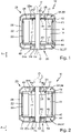
- figure 1 an exemplary embodiment of an electrical machine in a schematic partially sectioned basic representation
- FIG figure 2 a further exemplary embodiment of the electrical machine in a representation according to FIG figure 1 ,
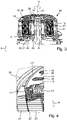
- figure 3 an embodiment of the electrical machine with a structure according to Figure 1 or Figure 2 in a perspective sectional view in a sectional plane along an axis of rotation
- figure 4 a partial representation of the embodiment according to FIG figure 3 in the area of an air gap between a stator and a rotor
- figure 5 a partial representation of the embodiment according to FIG figure 3 in the area of a radially inner end of a first shielding unit of the electrical machine
- figure 6 a partial representation of the embodiment according to FIG figure 3 in the area of a second shielding unit of the electrical machine
- figure 7 an electrical equivalent circuit diagram of a network of parasitic capacitances of the electrical machine with a structure accordingly figure 1 ,
- figure 8 an electrical equivalent circuit diagram of a network of parasitic capacitances of the electrical machine with a structure of the electrical machine according to Figure 2,
- figure 9 a block diagram of an electrical circuit for controlling an electrical machine according to the invention.
- figure 10 a perspective partial representation of a modified embodiment for forming an opening in a screen unit.
- an exemplary embodiment of an electrical machine 10 is illustrated in each case, which can be operated as a motor and can thus form an electric motor.
- the electrical machine 10 is, for example, an electrical machine that can be operated with AC voltage, preferably multi-phase and, for example, three-phase AC voltage.
- the operation of an electrical machine 10 using three-phase AC voltage is shown schematically in figure 9 illustrated.
- the electrical machine 10 is connected via a converter circuit 11 to phase voltages U 1 , U 2 , U 3 of a three-phase AC voltage supply network.
- the converter circuit 11 has a rectifier 12 in the exemplary embodiment, which rectifies the three-phase AC voltage and provides a DC voltage in a DC voltage intermediate circuit 13, which is provided by means of an inverter 14 of the converter circuit 11 in a multi-phase and, for example, three-phase AC voltage for generating a rotary field in the electrical machine 10.
- a rectifier 12 in the exemplary embodiment, which rectifies the three-phase AC voltage and provides a DC voltage in a DC voltage intermediate circuit 13, which is provided by means of an inverter 14 of the converter circuit 11 in a multi-phase and, for example, three-phase AC voltage for generating a rotary field in the electrical machine 10.
- Other converter topologies can also be used.
- the multi-phase AC voltage provided for the electrical machine 10 for generating the rotating field by the converter circuit 11 is not always equal to zero, and this results in a common-mode voltage U CM , which is also referred to as common mode .
- This common-mode voltage can form a network of parasitic capacitances on components of the electrical machine that are not completely short-circuited and are separated from one another, for example by a lubricant, air or the like, as is shown schematically in FIGS Figures 7 and 8 for different embodiments according to Figures 1 and 2 is illustrated. If the common-mode voltage exceeds a certain amount, a breakdown can occur between the components of the electric machine that form the parasitic capacitance, which can result in damage or increased wear. These effects are intended to be reduced and ideally eliminated by means of the present invention.
- the electrical machine 10 has a stator 17 , an electrically conductive winding support 18 and a stator winding 19 .
- the stator winding 19 has a plurality of winding groups which are electrically separate from one another, for example three winding groups.
- the winding carrier 18 is arranged on a central body 24 of the stator 17 which extends along an axis of rotation D.
- the central body 24 can be pin-shaped or sleeve-shaped.
- the radially outwardly pointing outer surface of the central body 24 is preferably stepless and, for example, is formed by a cylinder jacket surface.
- the bobbin 18 and optionally also the central body 24 is or are electrically conductive and electrically connected to ground PE, which is in the Figures 7 and 8 can be seen in the electrical equivalent circuit diagram.
- the stator winding 19 is electrically insulated from the winding support 18 .
- the electrical machine 10 also has a rotor 20 which is rotatably mounted about the axis of rotation D and can be driven in rotation about the axis of rotation D by means of a rotating field generated by the stator winding 19 .
- the rotor 20 can have permanent magnets 21 .
- An air gap 22 is formed in a radial direction radially to the axis of rotation D between the permanent magnets 21 of the rotor 20 and teeth 23 of the winding carrier 18 .
- the teeth 23 are separated from one another in the circumferential direction U by not-shown slots, conductor sections of the stator winding 19 running in the slots.
- the rotor 20 is rotatably mounted about the axis of rotation D by means of a bearing arrangement, with the bearing arrangement 27 being able to be supported, for example, on the central body 24 or also on another part of the stator 17 .
- the bearing assembly 27 has a first bearing 28 and a second bearing 29, which in an axial direction A, parallel to the axis of rotation D, are arranged at a distance from one another.
- the winding carrier 18 is arranged in the axial direction A between the first bearing 28 and the second bearing 29 .
- Each bearing 28, 29 has an outer ring 28a, 29a and an inner ring 28i, 29i.
- the outer rings 28a, 29a are mechanically connected to the rotor 20, while the inner rings 28i, 29i are arranged on a stationary part and on the central body 24, for example.
- the bearings 28, 29 are designed as roller bearings, so that rolling elements 30, for example balls, are arranged between the respective outer ring 28a, 29a and the associated inner ring 28i, 29i.
- the electrical machine 10 also has a first shield unit 34 adjacent to the first bearing 28 and a second shield unit 35 adjacent to the second bearing 29.
- the two shield units 34, 35 are each formed by an integral component, namely a first shield element 36 and a second screen element 37.
- the screen units 34, 35 could also each be designed in several parts.
- the first shielding element 36 has a first annular part 38 which extends from a radially inner end 39 of the first shielding unit 34 or the first shielding element 36 to a radially outer end 40 of the first shielding unit 34 or the first shielding element 36.
- the first shielding unit 34 or the first shielding element 36 has a first peripheral part which extends coaxially to the axis of rotation D 41 on.
- the first peripheral part 41 extends, for example, along a cylinder jacket surface arranged coaxially to the axis of rotation D. Starting from the first ring part 38 , the first peripheral part 41 extends in the axial direction A towards the second screen unit 35 .
- the first peripheral part 41 protrudes in the axial direction A over the adjacent axial end of the stator winding 19, which is also referred to as the end winding.
- the axial end of the stator winding 19 and the first peripheral part 41 are arranged in the axial direction A in an overlapping manner.
- the second screen unit 35 and the second screen element 37 are constructed analogously to the first screen unit 34 and the first screen element 36 .
- the second screen element 37 has a second annular part 42 which extends from a radially inner end 43 of the second screen unit 35 or the second screen element 37 to a radially outer end 44 of the second screen unit 35 or the second screen element 37 .
- the second shield unit 35 or the second shield element 37 has a second peripheral part 45 which extends coaxially to the axis of rotation D.
- the second peripheral part 45 extends, for example, along a cylindrical surface arranged coaxially to the axis of rotation D. Starting from the second ring part 42 , the second peripheral part 45 extends in the axial direction A towards the first screen unit 34 .
- the second peripheral part 45 protrudes in the axial direction A over the adjacent axial end of the stator winding 19, which is also referred to as the end winding.
- the axial end of the stator winding 19 and the second peripheral part 45 are arranged in the axial direction A in an overlapping manner.
- the radially inner ends 39, 43 are according to the example directly mechanically connected to the central body 24 and thereby preferably establish an electrical connection between the central body 24 and the relevant shielding unit 34 or 35 .
- the shielding units 34, 35 are thus electrically connected via the central body 24 to a reference potential (here: ground potential GND) or earth PE.
- the electrical machine delimits a space in which the shielding units 34, 35 are arranged. No part of the screen units 34, 35 protrudes from this space.
- the first ring portion 38 and the second ring portion 42 can, as in the Figures 1 and 2 schematically illustrated, extend parallel to a plane which is perpendicular to the axis of rotation D oriented.
- Each ring part 38, 42 can have an outer ring section 46 and an inner ring section 47.
- the outer ring portion 46 extends substantially parallel to a plane perpendicular to the axis of rotation D .
- the inner ring part 47 extends obliquely inclined with respect to the axis of rotation D and as a result has a conical shape which widens towards the outer ring section 46 . This is in figure 6 exemplified for the second ring portion 42 illustrated.
- openings 48 which are regularly spaced apart from one another in the circumferential direction U.
- the openings 48 extend, for example, following the respective radially outer end 40, 44 in the radial direction Axis of rotation D and preferably end at a distance from the respective radially inner end 39, 43.
- the openings 48 are present in the annular part 38, 42 where the annular part 38, 42 extends along the stator winding 19. Two openings 48 immediately adjacent in the circumferential direction U are separated from one another by a web 49 of the ring part 38 or 42, respectively.
- a rotating field is generated via the stator winding 19
- electromagnetic stray fields also arise in the axial direction A, which can generate eddy currents in the shielding units 34, 35 and thus losses.
- Such eddy current losses are at least reduced by the openings 48 adjacent to the axial ends of the stator winding 19 .
- the openings 48 can be used to cool the winding carrier 18 or the stator winding 19 .
- a fan wheel can be arranged on the rotor 20 in order to transport the cooling air.
- the rim delimiting each aperture 48 may have a course that does not extend entirely within a single plane.
- at least one section of the rim can have an axial position in the circumferential direction that deviates from the axial position of the opposite section of the rim.
- the edge sections of the opening 48 extending at least essentially in the radial direction can be arranged offset relative to one another in the axial direction A.
- a first edge section 51 can be arranged on an air guiding part 50 which protrudes obliquely over the opening 48 .
- a circumferential The opposite second edge section 52 is offset in the axial direction A to the first edge section 51 .
- the air guiding part 50 can be connected integrally or monolithically to the immediately adjoining web 49 .
- the air guiding part 50 can be produced, for example, when the opening 48 is produced by forming a separating groove along the second edge section 52 of the opening 48 and bending over the area delimited by the separating groove. As a result, the transport of cooling air to the stator winding 19 can be improved.
- the air guiding part 50 is preferably arranged on the side of the opening 48 facing away from the flow in the air flow direction. According to the example, the air guiding part 50 protrudes from the respective screen unit 34, 35 to the part of the stator 17 which is axially directly adjacent.
- FIG 10 the first screen unit 34 is shown merely by way of example.
- the openings 48 in the second screen unit 35 can be implemented analogously.
- the peripheral parts 41, 45 have openings, analogously to the ring parts 38, 42, but can alternatively also be without openings.
- the peripheral parts 41, 45 extend in the peripheral direction U around the axis of rotation D, it being possible for the openings in the peripheral direction U to be distributed uniformly.
- the parasitic capacitance C Y can be omitted, for example if there is no EMC filter and/or if no Y capacitors are installed in the converter.
- the shielding units 34, 35 are either grounded (short-circuited to ground PE) or via an impedance Z with connected to ground potential GND or another fixed reference potential.
- the impedance Z can have an ohmic component and/or a capacitive component and/or an inductive component.
- the screen units 34, 35 are electrically conductive, but preferably not ferromagnetic. You shield the electrical stray fields of the stator winding 19 at least partially and therefore influence the parasitic capacitances of the electrical machine, as shown schematically in the Figures 7 and 8 is illustrated.
- the following parasitic capacitances CWAs , CWAr and CWR between the stator winding 19 and the rotor 20 are reduced and the capacitive coupling between the stator winding 19 and the rotor 20 is reduced and ideally eliminated.
- the parasitic capacitance C RS between the rotor 20 and the stator 17 or winding carrier 18 and/or central body 24 is reduced or eliminated.
- the parasitic capacitance and thus the capacitive coupling between the rotor 20 and the stator 17 can also be reduced and ideally eliminated. Because of the grounded shield units 34, 35, the capacitive coupling between the rotor 20 and ground PE increases.
- the invention relates to an electrical machine 10 having a stator 17, a rotor 20, a bearing assembly 27 with a first bearing 28 and a second Bearings 29 on opposite sides of the stator 17 and a screen arrangement having a first screen unit 34 and a second screen unit 35.
- the rotor 20 is rotatably mounted about an axis of rotation D via the bearings 28, 29.
- the screen units 34, 35 are electrically conductive and each have an annular part 38, 42 which extends away from the axis of rotation D, starting from a radially inner end 39, 43 to a radially outer end 40, 44.
- Each shield unit 34, 35 preferably has a peripheral part 41, 45 at the radially outer end 40, 44, which extends in a ring shape continuously around the axis of rotation D and is arranged in the axial direction A so that it overlaps with the adjacent axial end of the stator winding 19 of the stator 17.
- the peripheral parts 41, 45 are preferably completely closed, whereas the ring parts 28, 42 can have openings 48.
Landscapes
- Engineering & Computer Science (AREA)
- Power Engineering (AREA)
- Physics & Mathematics (AREA)
- Electromagnetism (AREA)
- Motor Or Generator Frames (AREA)
Applications Claiming Priority (1)
| Application Number | Priority Date | Filing Date | Title |
|---|---|---|---|
| DE102021103277.6A DE102021103277A1 (de) | 2021-02-11 | 2021-02-11 | Elektrische Maschine mit geerdeter Schirmanordnung |
Publications (4)
| Publication Number | Publication Date |
|---|---|
| EP4044411A2 true EP4044411A2 (fr) | 2022-08-17 |
| EP4044411A3 EP4044411A3 (fr) | 2022-08-31 |
| EP4044411C0 EP4044411C0 (fr) | 2025-04-09 |
| EP4044411B1 EP4044411B1 (fr) | 2025-04-09 |
Family
ID=80122570
Family Applications (1)
| Application Number | Title | Priority Date | Filing Date |
|---|---|---|---|
| EP22153940.6A Active EP4044411B1 (fr) | 2021-02-11 | 2022-01-28 | Machine électrique pourvue d'agencement de blindage mis à la terre |
Country Status (4)
| Country | Link |
|---|---|
| US (1) | US11962218B2 (fr) |
| EP (1) | EP4044411B1 (fr) |
| CN (1) | CN114928213A (fr) |
| DE (1) | DE102021103277A1 (fr) |
Families Citing this family (7)
| Publication number | Priority date | Publication date | Assignee | Title |
|---|---|---|---|---|
| US12212189B2 (en) * | 2020-07-31 | 2025-01-28 | Mitsubishi Electric Corporation | Rotating electrical machine |
| DE102021103277A1 (de) * | 2021-02-11 | 2022-08-11 | Ebm-Papst Mulfingen Gmbh & Co. Kg | Elektrische Maschine mit geerdeter Schirmanordnung |
| CN115765331A (zh) * | 2022-11-21 | 2023-03-07 | 淮安威灵电机制造有限公司 | 电机 |
| KR102781729B1 (ko) | 2023-03-22 | 2025-03-17 | 현대모비스 주식회사 | 절연구조물 |
| DE102023109815A1 (de) * | 2023-04-19 | 2024-10-24 | Schaeffler Technologies AG & Co. KG | E-Maschine mit einer Abschirmstruktur zur Reduktion einer kapazitiven Kopplung in dieser sowie eine Axialflussmaschine mit der Abschirmstruktur |
| CN120415011A (zh) * | 2024-01-30 | 2025-08-01 | 宁德时代(上海)智能科技有限公司 | 电机和动力总成 |
| DE102024126994A1 (de) * | 2024-09-19 | 2026-03-19 | Schaeffler Technologies AG & Co. KG | Elektrische Maschine mit einer in einem Luftspalt angeordneten Abschirmstruktur |
Citations (4)
| Publication number | Priority date | Publication date | Assignee | Title |
|---|---|---|---|---|
| US7113365B1 (en) | 2002-12-24 | 2006-09-26 | Western Digital Technologies, Inc. | Disk drive comprising a spindle motor having a windings shield for reduced disk voltage coupling |
| JP2008263698A (ja) | 2007-04-11 | 2008-10-30 | Daikin Ind Ltd | 電動機 |
| US20180298908A1 (en) | 2015-06-29 | 2018-10-18 | Valeo Systemes Thermiques | Electric motor for an air blowing device and air blowing device |
| WO2019030181A1 (fr) | 2017-08-09 | 2019-02-14 | Ebm-Papst Mulfingen Gmbh & Co. Kg | Dispositif pour la réduction de tensions de palier préjudiciables |
Family Cites Families (8)
| Publication number | Priority date | Publication date | Assignee | Title |
|---|---|---|---|---|
| US3701911A (en) * | 1971-05-20 | 1972-10-31 | Skf Ind Trading & Dev | Motor bearing support and cooling means |
| JP3747684B2 (ja) * | 1999-04-09 | 2006-02-22 | 日本精工株式会社 | 電動モータおよびこれに使用される転がり軸受 |
| JP5217205B2 (ja) | 2007-03-27 | 2013-06-19 | ソニー株式会社 | モータ |
| EP2546958B1 (fr) * | 2010-03-10 | 2017-10-18 | Mitsubishi Electric Corporation | Rotor de moteur électrique, moteur électrique, conditionneur d'air, et procédé de fabrication de rotor de moteur électrique |
| FR3036892B1 (fr) * | 2015-05-29 | 2018-07-06 | Valeo Systemes Thermiques | Moteur electrique a commutation electronique et dispositif de pulsion d'air correspondant |
| FR3043280B1 (fr) * | 2015-10-29 | 2019-03-22 | Valeo Systemes Thermiques | Moteur electrique a commutation electronique et dispositif de pulsion d'air correspondant |
| DE102021103277A1 (de) * | 2021-02-11 | 2022-08-11 | Ebm-Papst Mulfingen Gmbh & Co. Kg | Elektrische Maschine mit geerdeter Schirmanordnung |
| JP7651878B2 (ja) * | 2021-02-19 | 2025-03-27 | ニデック株式会社 | バスバーユニットの製造方法、バスバーユニット、モータ |
-
2021
- 2021-02-11 DE DE102021103277.6A patent/DE102021103277A1/de active Pending
-
2022
- 2022-01-28 EP EP22153940.6A patent/EP4044411B1/fr active Active
- 2022-02-10 CN CN202210125181.5A patent/CN114928213A/zh active Pending
- 2022-02-11 US US17/669,974 patent/US11962218B2/en active Active
Patent Citations (4)
| Publication number | Priority date | Publication date | Assignee | Title |
|---|---|---|---|---|
| US7113365B1 (en) | 2002-12-24 | 2006-09-26 | Western Digital Technologies, Inc. | Disk drive comprising a spindle motor having a windings shield for reduced disk voltage coupling |
| JP2008263698A (ja) | 2007-04-11 | 2008-10-30 | Daikin Ind Ltd | 電動機 |
| US20180298908A1 (en) | 2015-06-29 | 2018-10-18 | Valeo Systemes Thermiques | Electric motor for an air blowing device and air blowing device |
| WO2019030181A1 (fr) | 2017-08-09 | 2019-02-14 | Ebm-Papst Mulfingen Gmbh & Co. Kg | Dispositif pour la réduction de tensions de palier préjudiciables |
Non-Patent Citations (2)
| Title |
|---|
| AUS K. VOSTROV ET AL.: "Shielding the end windings to reduce bearing currents", INTERNATIONAL CONFERENCE ON ELECTRICAL MACHINES (ICEM), 2020, pages 1431 - 1437, XP033868231, DOI: 10.1109/ICEM49940.2020.9270673 |
| F. J. T. E. FERREIRA ET AL.: "Evaluation of Slot-Embedded Partial Electrostatic Shield for High-Frequency Bearing Current Mitigation in Inverter-Fed Induction Motors", IEEE TRANSACTIONS ON ENERGY CONVERSI, vol. 27, no. 2, June 2012 (2012-06-01), pages 382 - 390, XP011444454, DOI: 10.1109/TEC.2012.2187452 |
Also Published As
| Publication number | Publication date |
|---|---|
| EP4044411C0 (fr) | 2025-04-09 |
| US20220255394A1 (en) | 2022-08-11 |
| DE102021103277A1 (de) | 2022-08-11 |
| EP4044411B1 (fr) | 2025-04-09 |
| EP4044411A3 (fr) | 2022-08-31 |
| US11962218B2 (en) | 2024-04-16 |
| CN114928213A (zh) | 2022-08-19 |
Similar Documents
| Publication | Publication Date | Title |
|---|---|---|
| EP4044411B1 (fr) | Machine électrique pourvue d'agencement de blindage mis à la terre | |
| DE69833081T2 (de) | Motor mit innerem Permanentmagnetrotor | |
| DE19522382C1 (de) | Transversalflußmaschine zum Einsatz in einem Direktantrieb für Fahrzeuge, insbesondere Bahnantrieb | |
| WO2010102987A1 (fr) | Transformateur tournant pour l'alimentation du bobinage d'excitation d'une machine dynamoélectrique | |
| WO1990009697A1 (fr) | Machine electrique excitee par des aimants permanents | |
| EP3504780B1 (fr) | Enroulement hélicoïdal à utilisation homogène du champ | |
| EP3665763B1 (fr) | Dispositif pour la réduction de tensions de palier préjudiciables | |
| EP3545610A1 (fr) | Machine synchrone à démultiplication magnétique de champ tournant et concentration de flux | |
| DE1813370C3 (de) | Kompoundiertes Erregersystem | |
| DE112020007302T5 (de) | Stator für elektrische drehmaschine | |
| DE3313747C2 (de) | Elektrische Maschine | |
| DE112019000730T5 (de) | Rotierende elektrische Maschine der Feldwicklungsbauart | |
| EP4699210A1 (fr) | Machine électrique dotée d'une structure de blindage permettant de réduire un couplage capacitif interne, et machine à flux axial ayant la structure de blindage | |
| WO2021148069A1 (fr) | Rotor et machine à flux axial | |
| DE19704769C2 (de) | Mehrsträngige Synchronmaschine mit Permanentmagneten und Spulenmodulen | |
| WO2025036530A1 (fr) | Machine électrique, en particulier machine à flux axial, dotée d'une structure de blindage | |
| EP3830912A1 (fr) | Corps à bagues collectrices | |
| EP3185405B1 (fr) | Moteur electrique | |
| EP3424129B1 (fr) | Machine asynchrone | |
| EP3207620B1 (fr) | Segment de stator pour un stator segmenté, creux et cylindrique d'une machine électrique | |
| WO2019110173A1 (fr) | Rotor ou stator d'une machine électrique | |
| WO2022128695A1 (fr) | Stator pour machine électrique et machine électrique pour entraîner un véhicule | |
| EP0087053B2 (fr) | Arrangement pour une excitation par thyristor rotatif | |
| WO2022042792A1 (fr) | Rotor refroidi d'une machine électrique | |
| EP3912256B1 (fr) | Moteur électrique |
Legal Events
| Date | Code | Title | Description |
|---|---|---|---|
| PUAI | Public reference made under article 153(3) epc to a published international application that has entered the european phase |
Free format text: ORIGINAL CODE: 0009012 |
|
| STAA | Information on the status of an ep patent application or granted ep patent |
Free format text: STATUS: THE APPLICATION HAS BEEN PUBLISHED |
|
| PUAL | Search report despatched |
Free format text: ORIGINAL CODE: 0009013 |
|
| AK | Designated contracting states |
Kind code of ref document: A2 Designated state(s): AL AT BE BG CH CY CZ DE DK EE ES FI FR GB GR HR HU IE IS IT LI LT LU LV MC MK MT NL NO PL PT RO RS SE SI SK SM TR |
|
| AK | Designated contracting states |
Kind code of ref document: A3 Designated state(s): AL AT BE BG CH CY CZ DE DK EE ES FI FR GB GR HR HU IE IS IT LI LT LU LV MC MK MT NL NO PL PT RO RS SE SI SK SM TR |
|
| RIC1 | Information provided on ipc code assigned before grant |
Ipc: H02K 11/40 20160101ALN20220726BHEP Ipc: H02K 11/01 20160101AFI20220726BHEP |
|
| STAA | Information on the status of an ep patent application or granted ep patent |
Free format text: STATUS: REQUEST FOR EXAMINATION WAS MADE |
|
| 17P | Request for examination filed |
Effective date: 20220913 |
|
| RBV | Designated contracting states (corrected) |
Designated state(s): AL AT BE BG CH CY CZ DE DK EE ES FI FR GB GR HR HU IE IS IT LI LT LU LV MC MK MT NL NO PL PT RO RS SE SI SK SM TR |
|
| STAA | Information on the status of an ep patent application or granted ep patent |
Free format text: STATUS: EXAMINATION IS IN PROGRESS |
|
| 17Q | First examination report despatched |
Effective date: 20240819 |
|
| GRAP | Despatch of communication of intention to grant a patent |
Free format text: ORIGINAL CODE: EPIDOSNIGR1 |
|
| STAA | Information on the status of an ep patent application or granted ep patent |
Free format text: STATUS: GRANT OF PATENT IS INTENDED |
|
| RIC1 | Information provided on ipc code assigned before grant |
Ipc: H02K 11/40 20160101ALN20241021BHEP Ipc: H02K 11/01 20160101AFI20241021BHEP |
|
| INTG | Intention to grant announced |
Effective date: 20241122 |
|
| GRAS | Grant fee paid |
Free format text: ORIGINAL CODE: EPIDOSNIGR3 |
|
| GRAA | (expected) grant |
Free format text: ORIGINAL CODE: 0009210 |
|
| STAA | Information on the status of an ep patent application or granted ep patent |
Free format text: STATUS: THE PATENT HAS BEEN GRANTED |
|
| AK | Designated contracting states |
Kind code of ref document: B1 Designated state(s): AL AT BE BG CH CY CZ DE DK EE ES FI FR GB GR HR HU IE IS IT LI LT LU LV MC MK MT NL NO PL PT RO RS SE SI SK SM TR |
|
| REG | Reference to a national code |
Ref country code: GB Ref legal event code: FG4D Free format text: NOT ENGLISH |
|
| REG | Reference to a national code |
Ref country code: CH Ref legal event code: EP |
|
| REG | Reference to a national code |
Ref country code: DE Ref legal event code: R096 Ref document number: 502022003473 Country of ref document: DE |
|
| REG | Reference to a national code |
Ref country code: IE Ref legal event code: FG4D Free format text: LANGUAGE OF EP DOCUMENT: GERMAN |
|
| U01 | Request for unitary effect filed |
Effective date: 20250429 |
|
| U07 | Unitary effect registered |
Designated state(s): AT BE BG DE DK EE FI FR IT LT LU LV MT NL PT RO SE SI Effective date: 20250507 |
|
| PG25 | Lapsed in a contracting state [announced via postgrant information from national office to epo] |
Ref country code: ES Free format text: LAPSE BECAUSE OF FAILURE TO SUBMIT A TRANSLATION OF THE DESCRIPTION OR TO PAY THE FEE WITHIN THE PRESCRIBED TIME-LIMIT Effective date: 20250409 |
|
| PG25 | Lapsed in a contracting state [announced via postgrant information from national office to epo] |
Ref country code: GR Free format text: LAPSE BECAUSE OF FAILURE TO SUBMIT A TRANSLATION OF THE DESCRIPTION OR TO PAY THE FEE WITHIN THE PRESCRIBED TIME-LIMIT Effective date: 20250710 Ref country code: NO Free format text: LAPSE BECAUSE OF FAILURE TO SUBMIT A TRANSLATION OF THE DESCRIPTION OR TO PAY THE FEE WITHIN THE PRESCRIBED TIME-LIMIT Effective date: 20250709 |
|
| PG25 | Lapsed in a contracting state [announced via postgrant information from national office to epo] |
Ref country code: PL Free format text: LAPSE BECAUSE OF FAILURE TO SUBMIT A TRANSLATION OF THE DESCRIPTION OR TO PAY THE FEE WITHIN THE PRESCRIBED TIME-LIMIT Effective date: 20250409 |
|
| PG25 | Lapsed in a contracting state [announced via postgrant information from national office to epo] |
Ref country code: HR Free format text: LAPSE BECAUSE OF FAILURE TO SUBMIT A TRANSLATION OF THE DESCRIPTION OR TO PAY THE FEE WITHIN THE PRESCRIBED TIME-LIMIT Effective date: 20250409 |
|
| PG25 | Lapsed in a contracting state [announced via postgrant information from national office to epo] |
Ref country code: RS Free format text: LAPSE BECAUSE OF FAILURE TO SUBMIT A TRANSLATION OF THE DESCRIPTION OR TO PAY THE FEE WITHIN THE PRESCRIBED TIME-LIMIT Effective date: 20250709 |
|
| PG25 | Lapsed in a contracting state [announced via postgrant information from national office to epo] |
Ref country code: IS Free format text: LAPSE BECAUSE OF FAILURE TO SUBMIT A TRANSLATION OF THE DESCRIPTION OR TO PAY THE FEE WITHIN THE PRESCRIBED TIME-LIMIT Effective date: 20250809 |
|
| PG25 | Lapsed in a contracting state [announced via postgrant information from national office to epo] |
Ref country code: SM Free format text: LAPSE BECAUSE OF FAILURE TO SUBMIT A TRANSLATION OF THE DESCRIPTION OR TO PAY THE FEE WITHIN THE PRESCRIBED TIME-LIMIT Effective date: 20250409 |
|
| PG25 | Lapsed in a contracting state [announced via postgrant information from national office to epo] |
Ref country code: CZ Free format text: LAPSE BECAUSE OF FAILURE TO SUBMIT A TRANSLATION OF THE DESCRIPTION OR TO PAY THE FEE WITHIN THE PRESCRIBED TIME-LIMIT Effective date: 20250409 |
|
| PG25 | Lapsed in a contracting state [announced via postgrant information from national office to epo] |
Ref country code: SK Free format text: LAPSE BECAUSE OF FAILURE TO SUBMIT A TRANSLATION OF THE DESCRIPTION OR TO PAY THE FEE WITHIN THE PRESCRIBED TIME-LIMIT Effective date: 20250409 |
|
| PLBE | No opposition filed within time limit |
Free format text: ORIGINAL CODE: 0009261 |
|
| STAA | Information on the status of an ep patent application or granted ep patent |
Free format text: STATUS: NO OPPOSITION FILED WITHIN TIME LIMIT |
|
| REG | Reference to a national code |
Ref country code: CH Ref legal event code: L10 Free format text: ST27 STATUS EVENT CODE: U-0-0-L10-L00 (AS PROVIDED BY THE NATIONAL OFFICE) Effective date: 20260218 |
|
| U20 | Renewal fee for the european patent with unitary effect paid |
Year of fee payment: 5 Effective date: 20260128 |
|
| 26N | No opposition filed |
Effective date: 20260112 |