EP4044411B1 - Machine électrique pourvue d'agencement de blindage mis à la terre - Google Patents
Machine électrique pourvue d'agencement de blindage mis à la terre Download PDFInfo
- Publication number
- EP4044411B1 EP4044411B1 EP22153940.6A EP22153940A EP4044411B1 EP 4044411 B1 EP4044411 B1 EP 4044411B1 EP 22153940 A EP22153940 A EP 22153940A EP 4044411 B1 EP4044411 B1 EP 4044411B1
- Authority
- EP
- European Patent Office
- Prior art keywords
- bearing
- electrical machine
- ring
- stator
- machine according
- Prior art date
- Legal status (The legal status is an assumption and is not a legal conclusion. Google has not performed a legal analysis and makes no representation as to the accuracy of the status listed.)
- Active
Links
Images

Classifications
-
- H—ELECTRICITY
- H02—GENERATION; CONVERSION OR DISTRIBUTION OF ELECTRIC POWER
- H02K—DYNAMO-ELECTRIC MACHINES
- H02K11/00—Structural association of dynamo-electric machines with electric components or with devices for shielding, monitoring or protection
- H02K11/01—Structural association of dynamo-electric machines with electric components or with devices for shielding, monitoring or protection for shielding from electromagnetic fields, i.e. structural association with shields
- H02K11/014—Shields associated with stationary parts, e.g. stator cores
-
- H—ELECTRICITY
- H02—GENERATION; CONVERSION OR DISTRIBUTION OF ELECTRIC POWER
- H02K—DYNAMO-ELECTRIC MACHINES
- H02K5/00—Casings; Enclosures; Supports
- H02K5/04—Casings or enclosures characterised by the shape, form or construction thereof
- H02K5/16—Means for supporting bearings, e.g. insulating supports or means for fitting bearings in the bearing-shields
- H02K5/173—Means for supporting bearings, e.g. insulating supports or means for fitting bearings in the bearing-shields using bearings with rolling contact, e.g. ball bearings
- H02K5/1732—Means for supporting bearings, e.g. insulating supports or means for fitting bearings in the bearing-shields using bearings with rolling contact, e.g. ball bearings radially supporting the rotary shaft at both ends of the rotor
-
- H—ELECTRICITY
- H02—GENERATION; CONVERSION OR DISTRIBUTION OF ELECTRIC POWER
- H02K—DYNAMO-ELECTRIC MACHINES
- H02K11/00—Structural association of dynamo-electric machines with electric components or with devices for shielding, monitoring or protection
- H02K11/01—Structural association of dynamo-electric machines with electric components or with devices for shielding, monitoring or protection for shielding from electromagnetic fields, i.e. structural association with shields
- H02K11/014—Shields associated with stationary parts, e.g. stator cores
- H02K11/0141—Shields associated with casings, enclosures or brackets
-
- H—ELECTRICITY
- H02—GENERATION; CONVERSION OR DISTRIBUTION OF ELECTRIC POWER
- H02K—DYNAMO-ELECTRIC MACHINES
- H02K11/00—Structural association of dynamo-electric machines with electric components or with devices for shielding, monitoring or protection
- H02K11/40—Structural association with grounding devices
Definitions
- the invention relates to an electrical machine comprising a stator, a rotor rotatable about an axis of rotation and a bearing arrangement for supporting the rotor.
- the electric machine In motor operation, the electric machine operates with an electromagnetic rotating field generated by a stator winding, which serves to move the rotor.
- the rotor can, for example, carry permanent magnets.
- the electric machine is not operated directly via one or more phases of the power supply network; instead, a converter, such as a frequency converter, is connected between the power supply network and the electric machine. If the electric machine is connected to a converter with a DC link, a time-varying common-mode voltage can arise between the stator winding and a reference potential (e.g., ground or earth). Due to this common-mode voltage, parasitic capacitances can become effective in the electric machine, which can then be responsible for increased wear or damage. For example, due to parasitic capacitance and depending on the magnitude of the common-mode voltage, breakdowns or arcs can form in the area of the bearing arrangement, which can damage both the bearing and the lubricant present in the bearing or cause increased wear.
- a converter such as a frequency converter
- WO 2019/030181 A1 describes an electrical machine in which a shield arrangement is present between the stator winding and the outer bearing rings of the bearing arrangement.
- the shield arrangement and the stator are each electrically connected to an electrical potential.
- both the stator and the shield arrangement can be connected to a ground potential of the electrical circuit.
- the stator has no potential connection, while the shield arrangement is grounded via an impedance.
- electrostatic shields to cover the end windings of the stator.
- the electrostatic shield can comprise one or more conductor loops that can be grounded.
- the conductor loops are arranged coaxially with the axis of rotation, adjacent to the air gap around the axial ends of the stator winding.
- US 7 113 365 B1 describes a disk drive with an electric motor.
- the electric motor has an annular stator with a cylindrical central body.
- a hub is arranged on the cylindrical central body, which is arranged in an axial direction parallel to the axis of rotation next to a stator winding.
- the hub carries magnets arranged radially outward from the stator winding. The hub and the magnets thus form the rotor.
- the stator winding and the rotor magnets are arranged outside the axial region, which is delimited by the two bearings.
- An electric motor with a stator comprising a sleeve-shaped central body and a shaft rotatably mounted in the sleeve-shaped central body for arranging the rotor is described in US 2018/0298908 A1 described.
- the shaft protrudes from the central body and has a rotor support plate extending radially to the axis of rotation. Permanent magnets of the rotor are arranged at the outer end of the plate and coaxially surround the stator winding.
- JP 2008-263698 A describes the possibility of electrically isolating the bearings of an electric motor from the stator.
- the first shielding unit may be formed by an integral or monolithic first shielding element.
- the second shielding unit may be formed by an integral or monolithic second shielding element.
- the first shield unit has a ring portion extending in a circumferential direction around the rotation axis.
- the first ring portion extends from a radially inner
- the end is inclined to a radially outer end and/or perpendicular to the axis of rotation.
- the radially inner end is arranged axially between the first bearing and the winding support and is mechanically connected to the central body.
- this mechanical connection also establishes an electrical connection between the first shield unit and the central body.
- the second shield unit also has a second ring portion extending circumferentially around the rotation axis.
- the second ring portion extends from a radially inner end outward to a radially outer end obliquely and/or perpendicular to the rotation axis.
- the radially inner end is arranged axially between the second bearing and the winding support and is mechanically connected to the central body.
- this mechanical connection also establishes an electrical connection between the second shield unit and the central body.
- the shield units are part of the stator and are arranged so that they cannot rotate relative to the central body.
- the first ring part and/or the second ring part has openings arranged at a distance from one another in the circumferential direction, the respective edges of which have a first edge section arranged on an air guide part.
- the air guide part projects obliquely over the opening.
- a second edge section of the edge of the respective opening, opposite in the circumferential direction, is arranged offset in the axial direction from the first edge section. This can improve the transport of cooling air to the stator winding.
- the second shielding unit can an annular second circumferential part which extends in the axial direction and in the circumferential direction around the axis of rotation and can form a closed ring in the circumferential direction or preferably has openings arranged at a distance from one another in the circumferential direction.
- the second circumferential part is connected to the second ring part at the radially outer end of the second shield unit.
- the optional openings in the first circumferential part and/or the second circumferential part are provided in the circumferential direction at the locations where a high air flow is preferably intended to be generated, for example, in the radial direction approximately aligned with a groove of the winding support located between two immediately adjacent teeth.
- the two teeth, or at least a portion of at least one adjacent tooth, can be covered by a web of the respective circumferential part extending substantially in the axial direction.
- the optional openings in the first peripheral part and/or the second peripheral part may be defined by an edge that does not extend within a single plane.
- at least one portion of the edge may protrude from a plane in which the at least one other portion of the edge extends.
- the first ring part and/or the second ring part each have a plurality of openings.
- the openings are arranged at a distance from one another in the circumferential direction in the respective ring part, preferably at regular intervals.
- the openings are, for example, delimited by a continuous edge of the ring part and are thus completely enclosed by the edge.
- the openings are preferably arranged along the stator winding or in the region of the stator winding.
- Each opening can have a width that increases with increasing distance from the axis of rotation in the circumferential direction and, when viewed in the axial direction, can have a trapezoidal shape, for example.
- Two openings that are immediately adjacent in the circumferential direction are separated from one another by a web of the first ring part or the second ring part.
- the optionally present circumferential parts preferably also have openings.
- the two shielding units or the two shielding elements are preferably not directly connected to one another mechanically and/or electrically, but are designed as separate shielding elements.
- the shielding elements or the shielding units are, for example, indirectly connected to one another mechanically and/or electrically, e.g., via the central body.
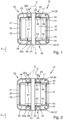
- FIG. 1 and 2 Each of the figures illustrates an embodiment of an electrical machine 10 that can be operated as a motor and thus can form an electric motor.
- the electrical machine 10 is, for example, an electrical machine that can be operated with alternating voltage, preferably multi-phase and, for example, three-phase alternating voltage.
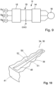
- the operation of an electrical machine 10 by means of three-phase alternating voltage is schematically shown in Figure 9 illustrated.
- the electrical machine 10 is connected via a converter circuit 11 to phase voltages U 1 , U 2 , U 3 of a three-phase AC voltage supply network.
- the converter circuit 11 has a rectifier 12, which rectifies the three-phase AC voltage and provides a DC voltage in a DC voltage intermediate circuit 13, which is converted by an inverter 14 of the converter circuit 11 into a multi-phase and, for example, three-phase AC voltage for generating a rotating field in the electrical machine 10.
- a rectifier 12 which rectifies the three-phase AC voltage and provides a DC voltage in a DC voltage intermediate circuit 13, which is converted by an inverter 14 of the converter circuit 11 into a multi-phase and, for example, three-phase AC voltage for generating a rotating field in the electrical machine 10.
- Other converter topologies can also be used.
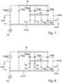
- the multi-phase alternating voltage provided to the electrical machine 10 for generating the rotating field by the converter circuit 11 is not always zero, and this results in a common-mode voltage U CM , which is also referred to as common mode .
- This common-mode voltage can cause components of the electrical machine that are not completely short-circuited and, for example, are protected by a lubricant, air or the like. separated from each other, form a network of parasitic capacities, as shown schematically in the Figures 7 and 8 for different embodiments according to the Figures 1 and 2 If the common-mode voltage exceeds a certain value, breakdown may occur between the components of the electrical machine that form the parasitic capacitance, which can result in damage or increased wear. These effects are to be reduced and, ideally, eliminated by means of the present invention.
- the electric machine 10 has a stator 17, an electrically conductive winding support 18, and a stator winding 19.
- the stator winding 19 has several electrically separated winding groups, for example, three winding groups.
- the winding support 18 is arranged, for example, on a central body 24 of the stator 17, which extends along a rotational axis D.
- the central body 24 can be pin-shaped or sleeve-shaped.
- the radially outward-facing outer surface of the central body 24 is preferably continuous and, for example, formed by a cylindrical jacket surface.
- the electric machine 10 also has a rotor 20 which is rotatably mounted about the rotation axis D and can be driven to rotate about the axis of rotation D by means of a rotating field generated by the stator winding 19.
- the rotor 20 can have permanent magnets 21.
- an air gap 22 is formed between the permanent magnets 21 of the rotor 20 and teeth 23 of the winding support 18.
- the teeth 23 are separated from one another in the circumferential direction U by grooves (not shown), with conductor sections of the stator winding 19 running in the grooves.
- the first shielding element 36 has a first ring part 38 which extends from a radially inner end 39 of the first shielding unit 34 or of the first shielding element 36 to a radially outer end 40 of the first shielding unit 34 or of the first shielding element 36.
- the first shielding unit 34 or the first shielding element 36 has a first circumferential part 41 which extends coaxially to the axis of rotation D.
- the first circumferential part 41 extends, for example, along a cylindrical jacket surface arranged coaxially to the axis of rotation D. Starting from the first ring part 38, the first circumferential part 41 extends in the axial direction A towards the second shielding unit 35.
- the second shielding unit 35 and the second shielding element 37 are constructed analogously to the first shielding unit 34 and the first shielding element 36.
- the second shielding element 37 has a second ring part 42, which extends from a radially inner end 43 of the second shielding unit 35 or the second shielding element 37 to a radially outer end 44 of the second shielding unit 35 or the second shielding element 37.
- the second shielding unit 35 or the second shielding element 37 has a second circumferential part 45 extending coaxially to the axis of rotation D.
- the second circumferential part 45 extends, for example, along a cylindrical jacket surface arranged coaxially to the axis of rotation D.
- the radially inner ends 39, 43 are, for example, directly mechanically connected to the central body 24 and preferably establish an electrical connection between the central body 24 and the respective shielding unit 34 or 35.
- the shielding units 34, 35 are thus electrically connected via the central body 24 to a reference potential (here: ground potential GND) or earth PE.
- the first ring part 38 and the second ring part 42 can, as in the Figures 1 and 2 schematically illustrated, extend parallel to a plane that is oriented perpendicular to the rotation axis D.
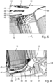
- Each ring part 38, 42 can have an outer ring section 46 and an inner ring section 47.
- the outer ring part 46 extends substantially parallel to a plane that is oriented perpendicular to the rotation axis D.
- the inner ring part 47 extends obliquely inclined relative to the rotation axis D and thereby has a conical shape that widens towards the outer ring section 46. This is in Figure 6 illustrated as an example for the second ring part 42.
- the parasitic capacitance and thus the capacitive coupling between the rotor 20 and the stator 17 can also be reduced and, ideally, eliminated. Due to the grounded shield units 34, 35, the capacitive coupling between the rotor 20 and ground PE increases.
- the first ring part 38 and/or the second ring part 42 has openings 48 arranged at a distance from one another in the circumferential direction U, the respective edge of which has a Air guiding part 50 arranged first edge portion 51, wherein the air guiding part 50 projects obliquely over the opening 48 and a second edge portion 52 of the edge of the respective opening 48, opposite in the circumferential direction U, is arranged offset in the axial direction A to the first edge portion 51.
Landscapes
- Engineering & Computer Science (AREA)
- Power Engineering (AREA)
- Physics & Mathematics (AREA)
- Electromagnetism (AREA)
- Motor Or Generator Frames (AREA)
Claims (15)
- Machine électrique (10) comprenant :- un stator (17) présentant un support d'enroulement (18) électriquement conducteur, relié électriquement à la terre (PE) ou à un potentiel de référence (GND), et un corps central (24), définissant un axe de rotation (D), et un enroulement de stator (19),- un ensemble de paliers (27) présentant un premier palier (28), disposé sur le corps central (24), et un deuxième palier (29) disposé sur le corps central (24), le support d'enroulement (18) du stator (17) étant disposé entre le premier palier (27) et le deuxième palier (29), parallèlement à l'axe de rotation (D), dans une direction axiale (A),- un rotor (20) monté avec possibilité de rotation autour de l'axe de rotation (D), à l'aide de l'ensemble de paliers (27),- une première unité de blindage (34) électriquement conductrice qui est reliée électriquement à la terre (PE) ou à un potentiel de référence (GND) et présente une première partie annulaire (38) qui s'étend sous une forme annulaire autour de l'axe de rotation (D), dans une direction périphérique (U), et s'étend depuis une extrémité radialement intérieure (39), radialement vers l'extérieur, vers une extrémité radialement extérieure (40), l'extrémité radialement intérieure (39) étant disposée entre le premier palier (28) et le support d'enroulement (18) et étant reliée au corps central (24),- une deuxième unité de blindage (35) électriquement conductrice qui est reliée électriquement à la terre (PE) ou à un potentiel de référence (GND) et présente une deuxième partie annulaire (42) qui s'étend sous une forme annulaire autour de l'axe de rotation (D), dans une direction périphérique (U), et s'étend depuis une extrémité radialement intérieure (43), radialement vers l'extérieur, vers une extrémité radialement extérieure (44), l'extrémité radialement intérieure (43) étant disposée entre le deuxième palier (29) et le support d'enroulement (18) et étant reliée au corps central (24), caractérisée en ce que la première partie annulaire (38) et/ou la deuxième partie annulaire (42) présente des ouvertures (48) qui sont disposées à distance les unes des autres dans la direction périphérique (U) et dont le bord respectif présente une première portion de bord (51) disposée sur un élément de guidage d'air (50), l'élément de guidage d'air (50) s'étendant en biais au-dessus de l'ouverture (48), et une deuxième portion de bord (52) du bord de l'ouverture (48) respective, située en vis-à-vis dans la direction périphérique (U), étant disposée avec un décalage dans la direction axiale (A) par rapport à la première portion de bord (51).
- Machine électrique selon la revendication 1, dans laquelle les deux unités de blindage (34, 35) sont disposées dans un espace qui est complètement entouré par le corps central (24), les deux paliers (28, 29) et le rotor (20).
- Machine électrique selon une des revendications précédentes, dans laquelle les unités de blindage (34, 35) sont reliées électriquement au corps central (24), par l'intermédiaire de leur partie annulaire (38, 42) respective, et sont reliées électriquement à la terre (PE) ou au potentiel de référence (GND), par l'intermédiaire du corps central (24).
- Machine électrique selon une des revendications précédentes, dans laquelle le corps central (24) est un manchon cylindrique ou une tige cylindrique.
- Machine électrique selon une des revendications précédentes, dans laquelle la première unité de blindage (34) présente une première partie périphérique (41) annulaire qui s'étend dans la direction axiale (A) et dans la direction périphérique (U), autour de l'axe de rotation (D), et est disposée entre l'enroulement de stator (19) et le rotor (20).
- Machine électrique selon une des revendications précédentes, dans laquelle la deuxième unité de blindage (35) présente une deuxième partie périphérique (45) annulaire qui s'étend dans la direction axiale (A) et dans la direction périphérique (U) et est disposée entre l'enroulement de stator (19) et le rotor (20).
- Machine électrique selon une des revendications précédentes, dans laquelle la première unité de blindage (34) est constituée d'un premier élément de blindage (36) réalisé d'une seule pièce, et/ou la deuxième unité de blindage (35) est constituée d'un deuxième élément de blindage (37) réalisé d'une seule pièce.
- Machine électrique selon une des revendications précédentes, dans laquelle l'élément de guidage d'air (50) est disposé sur le côté de l'ouverture (48) qui est détourné de l'écoulement, dans le sens de l'écoulement de l'air.
- Machine électrique selon une des revendications précédentes, dans laquelle l'élément de guidage d'air (50) s'étend à partir de l'unité de blindage (34, 35) respective, en direction de la partie du stator (17) qui est directement adjacente dans le sens axial.
- Machine électrique selon une des revendications précédentes, dans laquelle deux ouvertures (48) directement adjacentes dans la direction périphérique (U) sont séparées l'une de l'autre par une entretoise de la première partie annulaire (38) ou de la deuxième partie annulaire (42), et l'élément de guidage d'air (50) étant relié de manière monolithique à l'entretoise (49) directement adjacente.
- Machine électrique selon une des revendications précédentes, dans laquelle les ouvertures (48) sont disposées dans une direction radiale, radialement par rapport à l'axe de rotation (D), en étant à peu près alignées respectivement par rapport à une rainure associée, chaque rainure étant disposée entre deux dents (23) directement adjacent du support d'enroulement (18).
- Machine électrique selon une des revendications précédentes, dans laquelle la première partie annulaire (38) et/ou la deuxième partie annulaire (42) présentent une portion annulaire extérieure (46) qui s'étend parallèlement à un plan orienté à angle droit par rapport l'axe de rotation (D).
- Machine électrique selon une des revendications précédentes, dans laquelle au moins une des deux parties annulaires (38, 42) présente une portion annulaire intérieure (47) qui s'étend en biais par rapport à l'axe de rotation (D).
- Machine électrique selon une des revendications précédentes, dans laquelle un isolateur intérieur (53) est disposé respectivement entre le premier palier (28) et le stator (17) et le deuxième palier (29) et le stator (17).
- Machine électrique selon une des revendications précédentes, dans laquelle un isolateur extérieur (54) est disposé respectivement entre le premier palier (28) et le rotor (20) et le deuxième palier (29) et le rotor (20).
Applications Claiming Priority (1)
| Application Number | Priority Date | Filing Date | Title |
|---|---|---|---|
| DE102021103277.6A DE102021103277A1 (de) | 2021-02-11 | 2021-02-11 | Elektrische Maschine mit geerdeter Schirmanordnung |
Publications (4)
| Publication Number | Publication Date |
|---|---|
| EP4044411A2 EP4044411A2 (fr) | 2022-08-17 |
| EP4044411A3 EP4044411A3 (fr) | 2022-08-31 |
| EP4044411C0 EP4044411C0 (fr) | 2025-04-09 |
| EP4044411B1 true EP4044411B1 (fr) | 2025-04-09 |
Family
ID=80122570
Family Applications (1)
| Application Number | Title | Priority Date | Filing Date |
|---|---|---|---|
| EP22153940.6A Active EP4044411B1 (fr) | 2021-02-11 | 2022-01-28 | Machine électrique pourvue d'agencement de blindage mis à la terre |
Country Status (4)
| Country | Link |
|---|---|
| US (1) | US11962218B2 (fr) |
| EP (1) | EP4044411B1 (fr) |
| CN (1) | CN114928213A (fr) |
| DE (1) | DE102021103277A1 (fr) |
Families Citing this family (7)
| Publication number | Priority date | Publication date | Assignee | Title |
|---|---|---|---|---|
| US12212189B2 (en) * | 2020-07-31 | 2025-01-28 | Mitsubishi Electric Corporation | Rotating electrical machine |
| DE102021103277A1 (de) * | 2021-02-11 | 2022-08-11 | Ebm-Papst Mulfingen Gmbh & Co. Kg | Elektrische Maschine mit geerdeter Schirmanordnung |
| CN115765331A (zh) * | 2022-11-21 | 2023-03-07 | 淮安威灵电机制造有限公司 | 电机 |
| KR102781729B1 (ko) | 2023-03-22 | 2025-03-17 | 현대모비스 주식회사 | 절연구조물 |
| DE102023109815A1 (de) * | 2023-04-19 | 2024-10-24 | Schaeffler Technologies AG & Co. KG | E-Maschine mit einer Abschirmstruktur zur Reduktion einer kapazitiven Kopplung in dieser sowie eine Axialflussmaschine mit der Abschirmstruktur |
| CN120415011A (zh) * | 2024-01-30 | 2025-08-01 | 宁德时代(上海)智能科技有限公司 | 电机和动力总成 |
| DE102024126994A1 (de) * | 2024-09-19 | 2026-03-19 | Schaeffler Technologies AG & Co. KG | Elektrische Maschine mit einer in einem Luftspalt angeordneten Abschirmstruktur |
Family Cites Families (12)
| Publication number | Priority date | Publication date | Assignee | Title |
|---|---|---|---|---|
| US3701911A (en) * | 1971-05-20 | 1972-10-31 | Skf Ind Trading & Dev | Motor bearing support and cooling means |
| JP3747684B2 (ja) * | 1999-04-09 | 2006-02-22 | 日本精工株式会社 | 電動モータおよびこれに使用される転がり軸受 |
| US7113365B1 (en) | 2002-12-24 | 2006-09-26 | Western Digital Technologies, Inc. | Disk drive comprising a spindle motor having a windings shield for reduced disk voltage coupling |
| JP5217205B2 (ja) | 2007-03-27 | 2013-06-19 | ソニー株式会社 | モータ |
| JP2008263698A (ja) | 2007-04-11 | 2008-10-30 | Daikin Ind Ltd | 電動機 |
| EP2546958B1 (fr) * | 2010-03-10 | 2017-10-18 | Mitsubishi Electric Corporation | Rotor de moteur électrique, moteur électrique, conditionneur d'air, et procédé de fabrication de rotor de moteur électrique |
| FR3036892B1 (fr) * | 2015-05-29 | 2018-07-06 | Valeo Systemes Thermiques | Moteur electrique a commutation electronique et dispositif de pulsion d'air correspondant |
| FR3038160B1 (fr) | 2015-06-29 | 2019-08-02 | Valeo Systemes Thermiques | Dispositif de pulsion d'air comportant un moteur electrique |
| FR3043280B1 (fr) * | 2015-10-29 | 2019-03-22 | Valeo Systemes Thermiques | Moteur electrique a commutation electronique et dispositif de pulsion d'air correspondant |
| DE102017118125A1 (de) | 2017-08-09 | 2019-02-14 | Ebm-Papst Mulfingen Gmbh & Co. Kg | Vorrichtung zur Reduzierung von schädlichen Lagerspannungen |
| DE102021103277A1 (de) * | 2021-02-11 | 2022-08-11 | Ebm-Papst Mulfingen Gmbh & Co. Kg | Elektrische Maschine mit geerdeter Schirmanordnung |
| JP7651878B2 (ja) * | 2021-02-19 | 2025-03-27 | ニデック株式会社 | バスバーユニットの製造方法、バスバーユニット、モータ |
-
2021
- 2021-02-11 DE DE102021103277.6A patent/DE102021103277A1/de active Pending
-
2022
- 2022-01-28 EP EP22153940.6A patent/EP4044411B1/fr active Active
- 2022-02-10 CN CN202210125181.5A patent/CN114928213A/zh active Pending
- 2022-02-11 US US17/669,974 patent/US11962218B2/en active Active
Also Published As
| Publication number | Publication date |
|---|---|
| EP4044411C0 (fr) | 2025-04-09 |
| US20220255394A1 (en) | 2022-08-11 |
| DE102021103277A1 (de) | 2022-08-11 |
| EP4044411A2 (fr) | 2022-08-17 |
| EP4044411A3 (fr) | 2022-08-31 |
| US11962218B2 (en) | 2024-04-16 |
| CN114928213A (zh) | 2022-08-19 |
Similar Documents
| Publication | Publication Date | Title |
|---|---|---|
| EP4044411B1 (fr) | Machine électrique pourvue d'agencement de blindage mis à la terre | |
| EP3665763B1 (fr) | Dispositif pour la réduction de tensions de palier préjudiciables | |
| EP3504780B1 (fr) | Enroulement hélicoïdal à utilisation homogène du champ | |
| EP3314728B1 (fr) | Machine synchrone à réluctance | |
| EP2989711B1 (fr) | Machine électrique refroidie par air avec nervures de refroidissement en tôle de stator | |
| DE112020007302T5 (de) | Stator für elektrische drehmaschine | |
| EP3631954B1 (fr) | Dispositif pour réduire des tensions de palier préjudiciables | |
| EP4699210A1 (fr) | Machine électrique dotée d'une structure de blindage permettant de réduire un couplage capacitif interne, et machine à flux axial ayant la structure de blindage | |
| DE102018211462B4 (de) | Elektrische rotierende maschine | |
| EP3830912B1 (fr) | Corps de bague collectrices | |
| EP3185405B1 (fr) | Moteur electrique | |
| EP3424129B1 (fr) | Machine asynchrone | |
| EP3207620B1 (fr) | Segment de stator pour un stator segmenté, creux et cylindrique d'une machine électrique | |
| DE102022126838A1 (de) | Verschränkungswerkzeug zum bilden von statorwicklungs-endwindungen | |
| EP0087053B2 (fr) | Arrangement pour une excitation par thyristor rotatif | |
| WO2022042792A1 (fr) | Rotor refroidi d'une machine électrique | |
| DE3606207A1 (de) | Rotor fuer eine supraleitende rotierende elektrische maschine | |
| EP3912256B1 (fr) | Moteur électrique | |
| DE102016220044A1 (de) | Helixartige Wicklung mit erhöhter Feldausnutzung | |
| DE102024128774A1 (de) | Elektrische Axialflussmaschine mit Statorfilter | |
| EP4336709A1 (fr) | Commande individuelle de conducteurs partiels d'un stator à barres conductrices d'une machine dynamo-électrique | |
| WO2022084029A1 (fr) | Machine électrique dotée d'une protection contre les courts-circuits inter-spires | |
| DE102022133366A1 (de) | Rotorblechpaket, Rotor, elektrische Maschine und Fahrzeug | |
| EP1037418B1 (fr) | Entraînement électrique avec moteur triphase alimenté par un convertisseur | |
| WO2025008026A1 (fr) | Mise à la terre et blindage d'un stator d'une machine à flux axial |
Legal Events
| Date | Code | Title | Description |
|---|---|---|---|
| PUAI | Public reference made under article 153(3) epc to a published international application that has entered the european phase |
Free format text: ORIGINAL CODE: 0009012 |
|
| STAA | Information on the status of an ep patent application or granted ep patent |
Free format text: STATUS: THE APPLICATION HAS BEEN PUBLISHED |
|
| PUAL | Search report despatched |
Free format text: ORIGINAL CODE: 0009013 |
|
| AK | Designated contracting states |
Kind code of ref document: A2 Designated state(s): AL AT BE BG CH CY CZ DE DK EE ES FI FR GB GR HR HU IE IS IT LI LT LU LV MC MK MT NL NO PL PT RO RS SE SI SK SM TR |
|
| AK | Designated contracting states |
Kind code of ref document: A3 Designated state(s): AL AT BE BG CH CY CZ DE DK EE ES FI FR GB GR HR HU IE IS IT LI LT LU LV MC MK MT NL NO PL PT RO RS SE SI SK SM TR |
|
| RIC1 | Information provided on ipc code assigned before grant |
Ipc: H02K 11/40 20160101ALN20220726BHEP Ipc: H02K 11/01 20160101AFI20220726BHEP |
|
| STAA | Information on the status of an ep patent application or granted ep patent |
Free format text: STATUS: REQUEST FOR EXAMINATION WAS MADE |
|
| 17P | Request for examination filed |
Effective date: 20220913 |
|
| RBV | Designated contracting states (corrected) |
Designated state(s): AL AT BE BG CH CY CZ DE DK EE ES FI FR GB GR HR HU IE IS IT LI LT LU LV MC MK MT NL NO PL PT RO RS SE SI SK SM TR |
|
| STAA | Information on the status of an ep patent application or granted ep patent |
Free format text: STATUS: EXAMINATION IS IN PROGRESS |
|
| 17Q | First examination report despatched |
Effective date: 20240819 |
|
| GRAP | Despatch of communication of intention to grant a patent |
Free format text: ORIGINAL CODE: EPIDOSNIGR1 |
|
| STAA | Information on the status of an ep patent application or granted ep patent |
Free format text: STATUS: GRANT OF PATENT IS INTENDED |
|
| RIC1 | Information provided on ipc code assigned before grant |
Ipc: H02K 11/40 20160101ALN20241021BHEP Ipc: H02K 11/01 20160101AFI20241021BHEP |
|
| INTG | Intention to grant announced |
Effective date: 20241122 |
|
| GRAS | Grant fee paid |
Free format text: ORIGINAL CODE: EPIDOSNIGR3 |
|
| GRAA | (expected) grant |
Free format text: ORIGINAL CODE: 0009210 |
|
| STAA | Information on the status of an ep patent application or granted ep patent |
Free format text: STATUS: THE PATENT HAS BEEN GRANTED |
|
| AK | Designated contracting states |
Kind code of ref document: B1 Designated state(s): AL AT BE BG CH CY CZ DE DK EE ES FI FR GB GR HR HU IE IS IT LI LT LU LV MC MK MT NL NO PL PT RO RS SE SI SK SM TR |
|
| REG | Reference to a national code |
Ref country code: GB Ref legal event code: FG4D Free format text: NOT ENGLISH |
|
| REG | Reference to a national code |
Ref country code: CH Ref legal event code: EP |
|
| REG | Reference to a national code |
Ref country code: DE Ref legal event code: R096 Ref document number: 502022003473 Country of ref document: DE |
|
| REG | Reference to a national code |
Ref country code: IE Ref legal event code: FG4D Free format text: LANGUAGE OF EP DOCUMENT: GERMAN |
|
| U01 | Request for unitary effect filed |
Effective date: 20250429 |
|
| U07 | Unitary effect registered |
Designated state(s): AT BE BG DE DK EE FI FR IT LT LU LV MT NL PT RO SE SI Effective date: 20250507 |
|
| PG25 | Lapsed in a contracting state [announced via postgrant information from national office to epo] |
Ref country code: ES Free format text: LAPSE BECAUSE OF FAILURE TO SUBMIT A TRANSLATION OF THE DESCRIPTION OR TO PAY THE FEE WITHIN THE PRESCRIBED TIME-LIMIT Effective date: 20250409 |
|
| PG25 | Lapsed in a contracting state [announced via postgrant information from national office to epo] |
Ref country code: GR Free format text: LAPSE BECAUSE OF FAILURE TO SUBMIT A TRANSLATION OF THE DESCRIPTION OR TO PAY THE FEE WITHIN THE PRESCRIBED TIME-LIMIT Effective date: 20250710 Ref country code: NO Free format text: LAPSE BECAUSE OF FAILURE TO SUBMIT A TRANSLATION OF THE DESCRIPTION OR TO PAY THE FEE WITHIN THE PRESCRIBED TIME-LIMIT Effective date: 20250709 |
|
| PG25 | Lapsed in a contracting state [announced via postgrant information from national office to epo] |
Ref country code: PL Free format text: LAPSE BECAUSE OF FAILURE TO SUBMIT A TRANSLATION OF THE DESCRIPTION OR TO PAY THE FEE WITHIN THE PRESCRIBED TIME-LIMIT Effective date: 20250409 |
|
| PG25 | Lapsed in a contracting state [announced via postgrant information from national office to epo] |
Ref country code: HR Free format text: LAPSE BECAUSE OF FAILURE TO SUBMIT A TRANSLATION OF THE DESCRIPTION OR TO PAY THE FEE WITHIN THE PRESCRIBED TIME-LIMIT Effective date: 20250409 |
|
| PG25 | Lapsed in a contracting state [announced via postgrant information from national office to epo] |
Ref country code: RS Free format text: LAPSE BECAUSE OF FAILURE TO SUBMIT A TRANSLATION OF THE DESCRIPTION OR TO PAY THE FEE WITHIN THE PRESCRIBED TIME-LIMIT Effective date: 20250709 |
|
| PG25 | Lapsed in a contracting state [announced via postgrant information from national office to epo] |
Ref country code: IS Free format text: LAPSE BECAUSE OF FAILURE TO SUBMIT A TRANSLATION OF THE DESCRIPTION OR TO PAY THE FEE WITHIN THE PRESCRIBED TIME-LIMIT Effective date: 20250809 |
|
| PG25 | Lapsed in a contracting state [announced via postgrant information from national office to epo] |
Ref country code: SM Free format text: LAPSE BECAUSE OF FAILURE TO SUBMIT A TRANSLATION OF THE DESCRIPTION OR TO PAY THE FEE WITHIN THE PRESCRIBED TIME-LIMIT Effective date: 20250409 |
|
| PG25 | Lapsed in a contracting state [announced via postgrant information from national office to epo] |
Ref country code: CZ Free format text: LAPSE BECAUSE OF FAILURE TO SUBMIT A TRANSLATION OF THE DESCRIPTION OR TO PAY THE FEE WITHIN THE PRESCRIBED TIME-LIMIT Effective date: 20250409 |
|
| PG25 | Lapsed in a contracting state [announced via postgrant information from national office to epo] |
Ref country code: SK Free format text: LAPSE BECAUSE OF FAILURE TO SUBMIT A TRANSLATION OF THE DESCRIPTION OR TO PAY THE FEE WITHIN THE PRESCRIBED TIME-LIMIT Effective date: 20250409 |
|
| PLBE | No opposition filed within time limit |
Free format text: ORIGINAL CODE: 0009261 |
|
| STAA | Information on the status of an ep patent application or granted ep patent |
Free format text: STATUS: NO OPPOSITION FILED WITHIN TIME LIMIT |
|
| REG | Reference to a national code |
Ref country code: CH Ref legal event code: L10 Free format text: ST27 STATUS EVENT CODE: U-0-0-L10-L00 (AS PROVIDED BY THE NATIONAL OFFICE) Effective date: 20260218 |
|
| U20 | Renewal fee for the european patent with unitary effect paid |
Year of fee payment: 5 Effective date: 20260128 |
|
| 26N | No opposition filed |
Effective date: 20260112 |