EP4045096B1 - Verfahren zur dekontamination von behältern und kappen und entsprechende dekontaminationseinheit - Google Patents
Verfahren zur dekontamination von behältern und kappen und entsprechende dekontaminationseinheit Download PDFInfo
- Publication number
- EP4045096B1 EP4045096B1 EP20768637.9A EP20768637A EP4045096B1 EP 4045096 B1 EP4045096 B1 EP 4045096B1 EP 20768637 A EP20768637 A EP 20768637A EP 4045096 B1 EP4045096 B1 EP 4045096B1
- Authority
- EP
- European Patent Office
- Prior art keywords
- containers
- caps
- conveying
- carousel
- gripping means
- Prior art date
- Legal status (The legal status is an assumption and is not a legal conclusion. Google has not performed a legal analysis and makes no representation as to the accuracy of the status listed.)
- Active
Links
Images


Classifications
-
- B—PERFORMING OPERATIONS; TRANSPORTING
- B67—OPENING, CLOSING OR CLEANING BOTTLES, JARS OR SIMILAR CONTAINERS; LIQUID HANDLING
- B67C—CLEANING, FILLING WITH LIQUIDS OR SEMILIQUIDS, OR EMPTYING, OF BOTTLES, JARS, CANS, CASKS, BARRELS, OR SIMILAR CONTAINERS, NOT OTHERWISE PROVIDED FOR; FUNNELS
- B67C7/00—Concurrent cleaning, filling, and closing of bottles; Processes or devices for at least two of these operations
- B67C7/0073—Sterilising, aseptic filling and closing
-
- A—HUMAN NECESSITIES
- A61—MEDICAL OR VETERINARY SCIENCE; HYGIENE
- A61L—METHODS OR APPARATUS FOR STERILISING MATERIALS OR OBJECTS IN GENERAL; DISINFECTION, STERILISATION OR DEODORISATION OF AIR; CHEMICAL ASPECTS OF BANDAGES, DRESSINGS, ABSORBENT PADS OR SURGICAL ARTICLES; MATERIALS FOR BANDAGES, DRESSINGS, ABSORBENT PADS OR SURGICAL ARTICLES
- A61L2/00—Disinfection or sterilisation of materials or objects, in general; Accessories therefor
- A61L2/02—Disinfection or sterilisation of materials or objects, in general; Accessories therefor using physical processes
- A61L2/08—Radiation
- A61L2/087—Particle radiation, e.g. electron-beam, alpha or beta radiation
-
- B—PERFORMING OPERATIONS; TRANSPORTING
- B67—OPENING, CLOSING OR CLEANING BOTTLES, JARS OR SIMILAR CONTAINERS; LIQUID HANDLING
- B67B—APPLYING CLOSURE MEMBERS TO BOTTLES JARS, OR SIMILAR CONTAINERS; OPENING CLOSED CONTAINERS
- B67B3/00—Closing bottles, jars or similar containers by applying caps
- B67B3/003—Pretreatment of caps, e.g. cleaning, steaming, heating or sterilizing
-
- B—PERFORMING OPERATIONS; TRANSPORTING
- B67—OPENING, CLOSING OR CLEANING BOTTLES, JARS OR SIMILAR CONTAINERS; LIQUID HANDLING
- B67C—CLEANING, FILLING WITH LIQUIDS OR SEMILIQUIDS, OR EMPTYING, OF BOTTLES, JARS, CANS, CASKS, BARRELS, OR SIMILAR CONTAINERS, NOT OTHERWISE PROVIDED FOR; FUNNELS
- B67C3/00—Bottling liquids or semiliquids; Filling jars or cans with liquids or semiliquids using bottling or like apparatus; Filling casks or barrels with liquids or semiliquids
- B67C3/02—Bottling liquids or semiliquids; Filling jars or cans with liquids or semiliquids using bottling or like apparatus
- B67C3/22—Details
- B67C3/24—Devices for supporting or handling bottles
-
- B—PERFORMING OPERATIONS; TRANSPORTING
- B67—OPENING, CLOSING OR CLEANING BOTTLES, JARS OR SIMILAR CONTAINERS; LIQUID HANDLING
- B67C—CLEANING, FILLING WITH LIQUIDS OR SEMILIQUIDS, OR EMPTYING, OF BOTTLES, JARS, CANS, CASKS, BARRELS, OR SIMILAR CONTAINERS, NOT OTHERWISE PROVIDED FOR; FUNNELS
- B67C7/00—Concurrent cleaning, filling, and closing of bottles; Processes or devices for at least two of these operations
- B67C7/0006—Conveying; Synchronising
- B67C7/004—Conveying; Synchronising the containers travelling along a circular path
-
- A—HUMAN NECESSITIES
- A61—MEDICAL OR VETERINARY SCIENCE; HYGIENE
- A61L—METHODS OR APPARATUS FOR STERILISING MATERIALS OR OBJECTS IN GENERAL; DISINFECTION, STERILISATION OR DEODORISATION OF AIR; CHEMICAL ASPECTS OF BANDAGES, DRESSINGS, ABSORBENT PADS OR SURGICAL ARTICLES; MATERIALS FOR BANDAGES, DRESSINGS, ABSORBENT PADS OR SURGICAL ARTICLES
- A61L2103/00—Materials or objects being the target of disinfection or sterilisation
- A61L2103/23—Containers other than laboratory or medical, e.g. bottles or mail
Definitions
- the field of the invention is that of the design and manufacture of plastic containers.
- the invention relates to a decontamination unit for a plastic container manufacturing machine.
- the container When the container is in its final form, it is filled and then capped before being packaged or palletized and shipped to distributors.
- the containers Prior to filling and capping, the containers are decontaminated so that all or part of the microorganisms present in the bottle, particularly during blowing, are eliminated and so that the contents of the container, once filled, cannot be degraded, particularly in its organoleptic qualities.
- the containers once in their final form, pass through a decontamination unit in which they are decontaminated, for example by being moved in front of decontamination radiation in the form of an electron beam which eliminates all or part of the microorganisms.
- caps which may also be in contact with the product contained in the containers, are also decontaminated and pass through a second decontamination unit, distant from the first decontamination unit, then are directed towards a capping machine which allows the caps to be fixed on the containers after filling them.
- the caps and containers each follow a different path to be decontaminated, and are brought together for the capping stage.
- caps or containers are stored in the open air before being used, or are transported in the open air, they can again be contaminated by microorganisms present in the ambient air for example.
- JP H11 1212 A US 2007/237672 A1 describe units for the decontamination of caps and containers.
- the invention aims in particular to overcome the drawbacks of the prior art. More specifically, the invention aims to propose a decontamination unit for a machine for manufacturing plastic containers, which is less expensive and less bulky compared to the units of the prior art.
- the invention also aims to provide such a decontamination unit which makes it possible to reduce the cycle time for the manufacture of plastic containers from obtaining the container to its hermetic sealing with a cap.
- the invention further aims to provide such a decontamination unit which is easy to maintain.
- the containers and stoppers have an axis and in which the containers and/or the stoppers are rotated around the axis at least during the step of emitting the decontamination radiation.
- the decontamination radiation comprises an electron beam.
- Such a decontamination unit thus makes it possible to carry out simultaneous decontamination of caps and containers.
- such a decontamination unit makes it possible to limit the amount of unused decontamination radiation, particularly between the necks of the containers since the caps are inserted between them. Part of the decontamination radiation initially lost is therefore used here.
- the first gripping means and the second gripping means are located in the same plane.
- This configuration of the decontamination unit facilitates the conveyance of containers and caps. Indeed, it is not necessary to multiply the number of carousels since a single carousel can convey both caps and containers.
- the gripping means comprise means for rotating the containers and caps on the processing carousel.
- the means of rotating the containers and caps on the treatment carousel allow the entire surface of the bodies and caps to be treated by the decontamination radiation during its exposure.
- the movement of the buffers between their use and rest positions is thus mechanically controlled so that it does not generate a dedicated energy-consuming command.
- the first gripping means comprise means for supporting the containers on the processing carousel.
- the movement of the bases between their use and rest positions is thus mechanically controlled so that it does not generate a dedicated energy-consuming command.
- each base is free to rotate in its position of use.
- the decontamination radiation comprises an electron beam.
- the first conveying means is adapted to cooperate with the support ring of the neck of the container.
- the cap does not have a support ring so that the first gripping means are clearly distinct from the second gripping means.
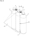
- FIG. 1 illustrates a machine 1 for manufacturing containers 2 made of plastic material according to the invention.
- the conventionally known blowing unit 3 makes it possible, from pre-heated plastic preforms, to obtain containers 2 having a definitive shape.
- the containers 2 leave the blowing unit 3, they are then directed towards the decontamination unit 4, so as to be decontaminated, that is to say to eliminate all or part of the microorganisms that they could contain, before generally filling them with a liquid.
- Stoppers 6, intended to close the containers 2, and generally manufactured by injection, are also decontaminated prior to their use for stopping the containers 2 in the stopping unit 5, when the containers 2 are filled.
- the capping unit 5 is supplied on the one hand by containers 2 filled according to a first supply line 7, and on the other hand by decontaminated caps 6, according to a second supply line 8.
- the caps 6 are then placed on the filled containers 2, in particular on their neck, so as to close them hermetically and thus confine the product they contain, generally a liquid.
- the stoppers 6 and the containers 2 are decontaminated each on their own before being brought together in the stoppering unit 5.
- FIG. 2 illustrates the decontamination unit 4 according to the invention, in which the caps 6 and the containers 2 are decontaminated simultaneously.
- the containers 2 are placed side by side and are moved in line one behind the other in the decontamination unit 4, and define between them an unoccupied spacing E.
- the unoccupied spacing E makes it possible to accommodate a stopper 6 to be decontaminated, as illustrated in the figures 2 , 3 And 4 .
- the decontamination unit 4 is connected to the first supply line 7 for containers 2 coming from the blowing unit 3 or from a buffer storage area, and to the second supply line 8 for caps 6 coming from a storage area or from a supply hopper.
- the input carousel 9 makes it possible to receive from each of the first supply line 7 and the second supply line 8 caps 6 and containers 2 to be decontaminated, in particular the neck of these containers 2.
- the decontamination unit 4 is configured so that the first contiguous gripping means 13 define between them a spacing E and that the second conveying means 16 are arranged relative to the first conveying means 12 to position the second gripping means 17 alternately with the first gripping means 13 in front of the emission means 14.
- the first gripping means 13 and the second gripping means 17 are in the form of a clamp, the two jaws of which are immobile relative to each other.
- the second gripping means are in the form of notches.
- the gripping means 13, 17 therefore take the shape of a U.
- the emission of the decontamination radiation 15 is carried out on a substantially rectangular window 18 illustrated in dotted lines.
- each container 2 is reached by the decontamination radiation 15.
- the decontamination radiation 15 scans both the container 2 but also an area devoid of material on either side of the neck.
- the decontamination radiation 15 then encounters the material of the stopper 6, thus allowing decontamination of the stoppers 6 simultaneously with the decontamination of the containers 2.
- first gripping means 13 and the second gripping means 17 are located in the same plane.
- the caps 6 are then located in the same plane as the necks of the containers 2.
- the gripping means 13, 17 carried by the processing carousel 10 are positioned at a lower level relative to the gripping means 13, 17 carried by the input carousel 9 and the output carousel 11.
- the gripping means 13, 17 carried by the processing carousel 10 are positioned at a higher level relative to the gripping means 13, 17 carried by the input carousel 10 and the output carousel 11.
- the gripping means 13, 17 of the output carousel 11 and the gripping means 13, 17 of the input carousel 10 are preferably coplanar.
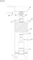
- the containers 2 and the caps 6 must be rotated 180°, so that their entire periphery is exposed to the decontamination radiation 15. This is achieved in particular by means of rotational drive means 19 and support means 20 illustrated in the figures 5 And 6 .
- the buffers 21 are made of an elastically deformable material such as rubber, or of an inert material which does not react to the decontamination radiation 15.
- This material makes it possible to resist the decontamination radiation 15 on the one hand, but also to modify its shape in contact with the containers 2 or the stoppers 6 to allow cooperation by friction causing the rotation of the stoppers 6 and the containers 2.
- the rotational drive means 19 When the containers 2 and the caps 6 are being taken over by the processing carousel 10, the rotational drive means 19 must be inoperative to allow the loading or unloading of the caps 6 and the containers 2 into or out of the processing carousel 10.
- each buffer 21 is thus controlled in movement by means of a cam path 23 and a roller 24 integral with the buffer 21, the roller 24 cooperating with the cam path 23.
- the cam path 23 is in the form of a crown mounted above the treatment carousel 10, and the roller 24 is connected to the buffer 21 by a rod 25.
- the rod 25 then passes through a frame 26 secured to the treatment carousel 10, and is mounted by means of return means 27 on said frame 26.
- the return means 27 make it possible to force the roller 24 to follow the cam path 23.
- the crown forming the cam path 23 thus has a surface having a boat 28 making it possible to position the roller 24 at a point distant from the treatment carousel 10.
- This boat then forms a portion in which the buffer 21 is in its rest position and therefore separated from the stoppers 6 and the containers 2.
- the buffers 21 are driven in rotation by the motor means 22 and, by friction, drive the stoppers 6 and the containers 2 in rotation in order to make them pivot during their passage in front of the decontamination radiation 15.
- the first gripping means 13 of the latter comprises, as described previously, support means 20.
- the support means 20 are positioned opposite the rotation drive means 19 of the containers 2 and are intended to receive the bottom of the containers 2.
- the support means 20 comprise a base 29 intended to cooperate with the bottom of the containers 2 to prevent them from becoming misaligned during their rotation, and thus force the containers to extend vertically between the rotation drive means 19 and the support means 20.
- the support means 20 must also be kept away.
- the bases 29 are each driven into their position of use or into their rest position by a cam track 30 and a roller 31 secured to the base.
- each roller 31 is secured to a base 29 by a rod 32 mounted in translation on the frame 26 of the drive carousel 10.
- the cam path 30 then also takes the form of a crown on which the rollers 31 are intended to circulate.
- the rod 32 is mounted through return means 33 on the frame of the treatment carousel 10, the return means 33 having the purpose of maintaining the rollers 31 of the support means 20 in contact with the cam path 30.
- the cam track 30 also has a boat 34 making it possible to move the roller 31 away from the treatment carousel 10, in particular in the rest position of the bases 29, to allow the exchange of containers 2 between the treatment carousel 10 and the input carousel 9 or the output carousel 11.
- the bases 29 are free to rotate, which prevents friction of the containers on the bases 29.
- the bases 29 follow the rotational movement of the containers 2 with which they cooperate.
- the containers 2 and the caps 6 are conveyed to the decontamination unit 4 by the first supply line 7 and the second supply line 8 respectively.
- Means for blocking the containers 2 and the caps 6 in their respective supply lines allow the passage of the caps 6 or the containers 2 towards the input carousel 9, so as to position a cap 6 between two consecutive containers 2.
- the containers 2 and the caps 6 are then driven towards the inside of the decontamination unit 4 by the input carousel 9, until they reach the treatment carousel 10, the containers and the caps then leaving the input carousel 9.
- the containers 2 and the stoppers 6 are housed respectively in the first gripping means 13 and the second gripping means 17 of the drive carousel 10.
- the drive carousel 10 is then rotated so as to expose the containers 2 and the caps 6 to the decontamination radiation 15.
- the rotation drive means 19 and the support means 20 come into contact with each of the containers 2 to allow their rotation, in particular when these are exposed to the decontamination radiation 15.
- the plugs 6 are also rotated by applying the buffers 21 of the rotation means 19 against the latter, the plugs 6 sliding, during their rotation, on the second gripping means 17.
- the caps 6 and the containers 2 are decontaminated, they are then directed by the treatment carousel 10 towards the output carousel 11, the latter, thanks to the first gripping means 13 and the second gripping means 17 which it comprises, then takes hold of the decontaminated caps 6 and containers 2 to direct them towards a conveyor line opening into the capping unit 5.
- the capping unit 5 also forms a filling unit so that the caps 6 and the filled containers 2 can be assembled.
- caps 6 between the necks of the containers 2 then makes it possible, in a single decontamination step, to decontaminate both the caps 6 and the containers 2, this to the benefit of the energy consumption of the manufacturing machine 1 since only one decontamination unit 4 is necessary, but also to the benefit of the compactness of the manufacturing machine 1, for these same reasons.
Landscapes
- Health & Medical Sciences (AREA)
- General Health & Medical Sciences (AREA)
- Epidemiology (AREA)
- Life Sciences & Earth Sciences (AREA)
- Animal Behavior & Ethology (AREA)
- Public Health (AREA)
- Veterinary Medicine (AREA)
- Mechanical Engineering (AREA)
- Engineering & Computer Science (AREA)
- Filling Of Jars Or Cans And Processes For Cleaning And Sealing Jars (AREA)
- Apparatus For Disinfection Or Sterilisation (AREA)
- Specific Conveyance Elements (AREA)
- Sealing Of Jars (AREA)
Claims (14)
- Verfahren zur Dekontamination einer Reihe von Kappen und einer Reihe von Behältern (2) aus Kunststoff, von denen jeder dazu bestimmt ist, mit einer der Kappen (6) der Reihe von Kappen verschlossen zu werden, wobei das Verfahren die folgenden Schritte umfasst:- Emittieren einer Dekontaminationsstrahlung (15) durch die Emissionsmittel (14),- Befördern der Reihe von Behältern durch erste Greifmittel (13) zu den Emissionsmitteln (14) gemäß einem Förderweg und- Befördern der Reihe von Kappen durch zweite Greifmittel (17) zu den Emissionsmitteln (14) gemäß einem Förderweg;dadurch gekennzeichnet, dass, beim Befördern der Reihe von Kappen und der Reihe von Behältern, die zweiten Greifmittel (17) entlang des Förderwegs mit den ersten Greifmitteln (13) vor den Emissionsmitteln (14) alternieren.
- Verfahren zur Dekontamination nach dem vorhergehenden Anspruch, wobei die Behälter und Kappen eine Achse aufweisen und wobei die Behälter und/oder die Kappen mindestens während des Schritts des Emittierens der Dekontaminationsstrahlung um die Achse herum in Drehung versetzt werden.
- Verfahren zur Dekontamination nach einem der vorhergehenden Ansprüche, dadurch gekennzeichnet, dass die Dekontaminationsstrahlung einen Elektronenstrahl umfasst.
- Dekontaminationseinheit (4) zur Implementierung des Verfahrens nach einem der vorhergehenden Ansprüche, umfassend:- Emissionsmittel (14) zum Emittieren einer Dekontaminationsstrahlung (15),- erste Fördermittel (12), die erste Greifmittel (13) aufweisen, und sie zu den Emissionsmitteln (14) zu befördern;- zweite Fördermittel (16), die zweite Greifmittel (17) aufweisen, um die Kappen (6) zu halten, und wobei die ersten Fördermittel (12) die ersten Greifmittel (13) zu den Emissionsmitteln (14) befördern,wobei zwei aneinandergrenzende erste Greifmittel (13) zwischen sich einen Abstand (E) definieren, dadurch gekennzeichnet, dass eines der zweiten Fördermittel (16) in dem Abstand zwischen den beiden aneinandergrenzenden ersten Fördermitteln (12) angeordnet ist, wobei es einen Förderabschnitt aufweist, in dem die zweiten Greifmittel (17) mit den ersten Greifmitteln (13) vor den Emissionsmitteln (14) alternieren.
- Dekontaminationseinheit (4) nach dem vorhergehenden Anspruch, dadurch gekennzeichnet, dass die ersten Greifmittel (13) und die zweiten Greifmittel (17) in einer selben Ebene gelegen sind.
- Dekontaminationseinheit (4) nach einem der Ansprüche 4 bis 5, dadurch gekennzeichnet, dass sie umfasst:- eine erste Beschickungslinie (7) zur Beschickung mit Behältern;- eine zweite Beschickungslinie (8) zur Beschickung mit Kappen;- ein Eingangskarussell (9), das mit der ersten Beschickungslinie (7) zur Beschickung mit Behältern (2) und mit der zweiten Beschickungslinie (8) zur Beschickung mit Kappen (6) in Verbindung steht;- ein Behandlungskarussell (10), das von dem Eingangskarussell (9) beschickt wird;- ein Ausgangskarussell (11), das von dem Behandlungskarussell (10) beschickt wird,wobei unter dem Eingangskarussell (9), dem Behandlungskarussell (10) und dem Ausgangskarussell (11) jedes die ersten Fördermittel (12) und die zweiten Fördermittel (16) trägt.
- Dekontaminationseinheit (4) nach dem vorhergehenden Anspruch, dadurch gekennzeichnet, dass die Greifmittel (13, 17) Drehantriebsmittel (19) für die Behälter (2) und die Kappen (6) auf dem Behandlungskarussell (10) umfassen.
- Dekontaminationseinheit (4) nach dem vorhergehenden Anspruch, dadurch gekennzeichnet, dass die Drehantriebsmittel (19) umfassen:- einen Puffer (21), der dazu bestimmt ist, mit den Behältern (2) und den Kappen (6) in Kontakt zu gelangen, um sie durch Reibung drehanzutreiben;- Motormittel (22), um die Puffer (21) in Drehung zu versetzen.
- Dekontaminationseinheit (4) nach dem vorhergehenden Anspruch, dadurch gekennzeichnet, dass die Puffer (21) beweglich sind zwischen:- einer Verwendungsstellung, in der die Puffer geeignet sind, mit den Behältern (2) oder den Kappen (6) in Kontakt zu sein;- einer Ruhestellung, in der sie von den Behältern (2) oder den Kappen (6) beabstandet sind,wobei jeder Puffer (21) durch eine Kulisse (23) und eine Rolle (24), die fest mit dem Puffer (21) verbunden ist, in seine Verwendungsstellung oder in seine Ruhestellung positioniert wird.
- Dekontaminationseinheit (4) nach einem der Ansprüche 6 bis 9, dadurch gekennzeichnet, dass die ersten Greifmittel (13) Stützmittel (20) für die Behälter (2) auf dem Behandlungskarussell (10) umfassen.
- Dekontaminationseinheit (4) nach dem vorhergehenden Anspruch, dadurch gekennzeichnet, dass die Stützmittel (20) Sockel (29) umfassen, die dazu bestimmt sind, einen Boden der Behälter (2) aufzunehmen, wobei jeder Sockel (29) beweglich ist zwischen:- einer Verwendungsstellung, in welcher der Sockel geeignet ist, mit dem Boden der Behälter (2) in Kontakt zu sein;- einer Ruhestellung, in der er von dem Boden der Behälter (2) beabstandet ist, wobei jeder Sockel (29) durch eine Kulisse (30) und eine Rolle (31), die fest mit dem Sockel (29) verbunden ist, in seine Verwendungsstellung oder in seine Ruhestellung positioniert wird.
- Dekontaminationseinheit (4) nach dem vorhergehenden Anspruch, dadurch gekennzeichnet, dass jeder Sockel (29) in seiner Verwendungsstellung drehbeweglich ist.
- Dekontaminationseinheit (4) nach einem der Ansprüche 4 bis 12, dadurch gekennzeichnet, dass das erste Fördermittel dazu angepasst ist, mit einem Stützring für den Hals des Behälters zusammenzuwirken.
- Maschine (1) zur Herstellung von Behältern, umfassend:- eine Blaseinheit (3);- eine Verschließeinheit (5);- eine Dekontaminationseinheit (4) nach einem der Ansprüche 4 bis 13,wobei die Dekontaminationseinheit (4) zwischen der Blaseinheit (3) und der Verschließeinheit (5) eingefügt ist.
Applications Claiming Priority (2)
| Application Number | Priority Date | Filing Date | Title |
|---|---|---|---|
| FR1910175A FR3100718B1 (fr) | 2019-09-16 | 2019-09-16 | Unité de décontamination pour machine de fabrication de récipients en matière plastique |
| PCT/EP2020/075852 WO2021053007A1 (fr) | 2019-09-16 | 2020-09-16 | Procede de decontamination de recipients et de bouchons et unite de decontamination correspondante |
Publications (2)
| Publication Number | Publication Date |
|---|---|
| EP4045096A1 EP4045096A1 (de) | 2022-08-24 |
| EP4045096B1 true EP4045096B1 (de) | 2025-05-14 |
Family
ID=68343144
Family Applications (1)
| Application Number | Title | Priority Date | Filing Date |
|---|---|---|---|
| EP20768637.9A Active EP4045096B1 (de) | 2019-09-16 | 2020-09-16 | Verfahren zur dekontamination von behältern und kappen und entsprechende dekontaminationseinheit |
Country Status (5)
| Country | Link |
|---|---|
| EP (1) | EP4045096B1 (de) |
| JP (1) | JP7636399B2 (de) |
| CN (1) | CN114423706B (de) |
| FR (1) | FR3100718B1 (de) |
| WO (1) | WO2021053007A1 (de) |
Family Cites Families (7)
| Publication number | Priority date | Publication date | Assignee | Title |
|---|---|---|---|---|
| IT1269899B (it) * | 1994-03-22 | 1997-04-16 | Ronchi Mario Srl Officine Mecc | Macchina automatica a dischi coassiali per il confezionamento di contenitori flessibili trasportati con moto continuo |
| JPH111212A (ja) * | 1997-06-11 | 1999-01-06 | Kirin Beverage Kk | 電子線による容器の滅菌装置 |
| ITMO20040111A1 (it) * | 2004-05-07 | 2004-08-07 | Sig Simonazzi Spa | Apparati e metodi per sterilizzare e riempire componenti di unita' di confezionamento,particolarmente bottiglie e-o tappi. |
| JP4889000B2 (ja) | 2005-12-27 | 2012-02-29 | 三菱重工食品包装機械株式会社 | 殺菌装置 |
| JP5558209B2 (ja) * | 2010-05-31 | 2014-07-23 | 三菱重工食品包装機械株式会社 | 電子線殺菌装置 |
| ITBS20110061A1 (it) * | 2011-04-26 | 2012-10-27 | Guala Pack Spa | Unità di ingresso o di uscita di un dispositivo di sterilizzazione afasci di elettroni e metodo di sterilizzazione |
| JP5772574B2 (ja) * | 2011-12-27 | 2015-09-02 | 澁谷工業株式会社 | 電子線キャップ殺菌装置 |
-
2019
- 2019-09-16 FR FR1910175A patent/FR3100718B1/fr active Active
-
2020
- 2020-09-16 JP JP2022516652A patent/JP7636399B2/ja active Active
- 2020-09-16 CN CN202080064571.5A patent/CN114423706B/zh active Active
- 2020-09-16 WO PCT/EP2020/075852 patent/WO2021053007A1/fr not_active Ceased
- 2020-09-16 EP EP20768637.9A patent/EP4045096B1/de active Active
Also Published As
| Publication number | Publication date |
|---|---|
| FR3100718A1 (fr) | 2021-03-19 |
| CN114423706A (zh) | 2022-04-29 |
| JP2022548124A (ja) | 2022-11-16 |
| WO2021053007A1 (fr) | 2021-03-25 |
| FR3100718B1 (fr) | 2023-05-12 |
| EP4045096A1 (de) | 2022-08-24 |
| JP7636399B2 (ja) | 2025-02-26 |
| CN114423706B (zh) | 2025-02-25 |
Similar Documents
| Publication | Publication Date | Title |
|---|---|---|
| EP3239079B1 (de) | Förderanlage für hohlkörper, die ein förderband zur verteilung und satelliteneinheiten zur bearbeitung umfasst | |
| EP2686259A1 (de) | Übertragungsvorrichtung mit einem greifer | |
| FR2911071A1 (fr) | Procede et equipement pour la decontamination par rayonnement d'un produit tel qu'un emballage contenant des dispositifs medicaux. | |
| EP3538459B1 (de) | System zum befördern von gegenständen aus einem thermoplastischen material mit einem hohlkörper mit einem hals | |
| WO2019129966A1 (fr) | Transfert de produits entre une zone de transit et une surface d'accumulation | |
| FR3104484A1 (fr) | Procédé d'indexation angulaire d'une préforme | |
| CH683757A5 (fr) | Machine modulaire intégrée pour la fabrication et le conditionnement de récipients en téréphtalate de polyéthylène bi-orienté et les modules de soufflage et remplissage la constituant. | |
| EP3606866B1 (de) | Anlage zur behandlung von behältern | |
| EP2720825A1 (de) | Vorrichtung zum positionieren von flaschen | |
| EP4045096B1 (de) | Verfahren zur dekontamination von behältern und kappen und entsprechende dekontaminationseinheit | |
| EP2632805B1 (de) | Vorrichtung und verfahren zum einwickeln identischer oder ähnlicher produkte und zur verpackung der eingewickelten produkte | |
| WO2007080327A2 (fr) | Recalibreur de bouteilles en matière plastique après traitement de stérilisation. | |
| EP3797968B1 (de) | Vorrichtung zum thermoformen, folienverschliessen und schneiden von behähltern von unterschiedlichen grössen | |
| WO2021234241A1 (fr) | Procédé automatisé de distribution d'obturateurs | |
| FR2494237A1 (fr) | Dispositif d'acheminement de bouteilles et recipients analogues, d'une machine de remplissage a une machine a boucher les bouteilles | |
| EP3424681B1 (de) | Vorrichtung zur behandlung von behältern, und entsprechende antriebsvorrichtung | |
| EP0083385B1 (de) | Verfahren zur Behandlung von Lebensmitteln in plastischen Behältern und Einrichtung hierfür, sowie zur Sterilisierung dieser Waren | |
| WO2005023652A1 (fr) | Procede et installation de formage et de remplissage de bouteilles en matiere thermoplastique | |
| FR3090457A1 (fr) | Procédé et système de traitement d’un flux de préformes en matière thermoplastique pour en orienter angulairement chacune des préformes dans une position de référence. | |
| WO2025056758A1 (fr) | Dispositif et procédé de transfert de récipients | |
| WO2026057601A1 (fr) | Installation de fabrication de récipients en matière thermoplastique comportant un dispositif de convoyage | |
| FR3164978A1 (fr) | Machine d’arrangement de bouteilles tête-bêche et ensemble d’encaissage comprenant une telle machine | |
| WO2024068822A1 (fr) | Procede de transfert de preforme sur un convoyeur | |
| FR3119606A1 (fr) | Dispositif et procédé de transport d'articles, tels que de récipients à boisson ou similaires | |
| FR2508423A1 (fr) | Dispositif pour la manipulation de boites, notamment de boites de conserves |
Legal Events
| Date | Code | Title | Description |
|---|---|---|---|
| STAA | Information on the status of an ep patent application or granted ep patent |
Free format text: STATUS: UNKNOWN |
|
| STAA | Information on the status of an ep patent application or granted ep patent |
Free format text: STATUS: THE INTERNATIONAL PUBLICATION HAS BEEN MADE |
|
| PUAI | Public reference made under article 153(3) epc to a published international application that has entered the european phase |
Free format text: ORIGINAL CODE: 0009012 |
|
| STAA | Information on the status of an ep patent application or granted ep patent |
Free format text: STATUS: REQUEST FOR EXAMINATION WAS MADE |
|
| 17P | Request for examination filed |
Effective date: 20220315 |
|
| AK | Designated contracting states |
Kind code of ref document: A1 Designated state(s): AL AT BE BG CH CY CZ DE DK EE ES FI FR GB GR HR HU IE IS IT LI LT LU LV MC MK MT NL NO PL PT RO RS SE SI SK SM TR |
|
| DAV | Request for validation of the european patent (deleted) | ||
| DAX | Request for extension of the european patent (deleted) | ||
| STAA | Information on the status of an ep patent application or granted ep patent |
Free format text: STATUS: EXAMINATION IS IN PROGRESS |
|
| 17Q | First examination report despatched |
Effective date: 20230918 |
|
| GRAP | Despatch of communication of intention to grant a patent |
Free format text: ORIGINAL CODE: EPIDOSNIGR1 |
|
| STAA | Information on the status of an ep patent application or granted ep patent |
Free format text: STATUS: GRANT OF PATENT IS INTENDED |
|
| INTG | Intention to grant announced |
Effective date: 20250128 |
|
| GRAS | Grant fee paid |
Free format text: ORIGINAL CODE: EPIDOSNIGR3 |
|
| GRAA | (expected) grant |
Free format text: ORIGINAL CODE: 0009210 |
|
| STAA | Information on the status of an ep patent application or granted ep patent |
Free format text: STATUS: THE PATENT HAS BEEN GRANTED |
|
| AK | Designated contracting states |
Kind code of ref document: B1 Designated state(s): AL AT BE BG CH CY CZ DE DK EE ES FI FR GB GR HR HU IE IS IT LI LT LU LV MC MK MT NL NO PL PT RO RS SE SI SK SM TR |
|
| REG | Reference to a national code |
Ref country code: GB Ref legal event code: FG4D Free format text: NOT ENGLISH |
|
| REG | Reference to a national code |
Ref country code: CH Ref legal event code: EP |
|
| P01 | Opt-out of the competence of the unified patent court (upc) registered |
Free format text: CASE NUMBER: APP_19365/2025 Effective date: 20250423 |
|
| REG | Reference to a national code |
Ref country code: IE Ref legal event code: FG4D Free format text: LANGUAGE OF EP DOCUMENT: FRENCH |
|
| REG | Reference to a national code |
Ref country code: DE Ref legal event code: R096 Ref document number: 602020051299 Country of ref document: DE |
|
| REG | Reference to a national code |
Ref country code: NL Ref legal event code: MP Effective date: 20250514 |
|
| PG25 | Lapsed in a contracting state [announced via postgrant information from national office to epo] |
Ref country code: PT Free format text: LAPSE BECAUSE OF FAILURE TO SUBMIT A TRANSLATION OF THE DESCRIPTION OR TO PAY THE FEE WITHIN THE PRESCRIBED TIME-LIMIT Effective date: 20250915 Ref country code: ES Free format text: LAPSE BECAUSE OF FAILURE TO SUBMIT A TRANSLATION OF THE DESCRIPTION OR TO PAY THE FEE WITHIN THE PRESCRIBED TIME-LIMIT Effective date: 20250514 Ref country code: FI Free format text: LAPSE BECAUSE OF FAILURE TO SUBMIT A TRANSLATION OF THE DESCRIPTION OR TO PAY THE FEE WITHIN THE PRESCRIBED TIME-LIMIT Effective date: 20250514 |
|
| PGFP | Annual fee paid to national office [announced via postgrant information from national office to epo] |
Ref country code: DE Payment date: 20250820 Year of fee payment: 6 |
|
| REG | Reference to a national code |
Ref country code: LT Ref legal event code: MG9D |
|
| PG25 | Lapsed in a contracting state [announced via postgrant information from national office to epo] |
Ref country code: GR Free format text: LAPSE BECAUSE OF FAILURE TO SUBMIT A TRANSLATION OF THE DESCRIPTION OR TO PAY THE FEE WITHIN THE PRESCRIBED TIME-LIMIT Effective date: 20250815 Ref country code: NO Free format text: LAPSE BECAUSE OF FAILURE TO SUBMIT A TRANSLATION OF THE DESCRIPTION OR TO PAY THE FEE WITHIN THE PRESCRIBED TIME-LIMIT Effective date: 20250814 |
|
| PG25 | Lapsed in a contracting state [announced via postgrant information from national office to epo] |
Ref country code: PL Free format text: LAPSE BECAUSE OF FAILURE TO SUBMIT A TRANSLATION OF THE DESCRIPTION OR TO PAY THE FEE WITHIN THE PRESCRIBED TIME-LIMIT Effective date: 20250514 Ref country code: NL Free format text: LAPSE BECAUSE OF FAILURE TO SUBMIT A TRANSLATION OF THE DESCRIPTION OR TO PAY THE FEE WITHIN THE PRESCRIBED TIME-LIMIT Effective date: 20250514 |
|
| PGFP | Annual fee paid to national office [announced via postgrant information from national office to epo] |
Ref country code: IT Payment date: 20250820 Year of fee payment: 6 |
|
| REG | Reference to a national code |
Ref country code: AT Ref legal event code: MK05 Ref document number: 1794279 Country of ref document: AT Kind code of ref document: T Effective date: 20250514 |
|
| PG25 | Lapsed in a contracting state [announced via postgrant information from national office to epo] |
Ref country code: BG Free format text: LAPSE BECAUSE OF FAILURE TO SUBMIT A TRANSLATION OF THE DESCRIPTION OR TO PAY THE FEE WITHIN THE PRESCRIBED TIME-LIMIT Effective date: 20250514 |
|
| PG25 | Lapsed in a contracting state [announced via postgrant information from national office to epo] |
Ref country code: HR Free format text: LAPSE BECAUSE OF FAILURE TO SUBMIT A TRANSLATION OF THE DESCRIPTION OR TO PAY THE FEE WITHIN THE PRESCRIBED TIME-LIMIT Effective date: 20250514 |
|
| PG25 | Lapsed in a contracting state [announced via postgrant information from national office to epo] |
Ref country code: AT Free format text: LAPSE BECAUSE OF FAILURE TO SUBMIT A TRANSLATION OF THE DESCRIPTION OR TO PAY THE FEE WITHIN THE PRESCRIBED TIME-LIMIT Effective date: 20250514 |
|
| PGFP | Annual fee paid to national office [announced via postgrant information from national office to epo] |
Ref country code: FR Payment date: 20250821 Year of fee payment: 6 |
|
| PG25 | Lapsed in a contracting state [announced via postgrant information from national office to epo] |
Ref country code: RS Free format text: LAPSE BECAUSE OF FAILURE TO SUBMIT A TRANSLATION OF THE DESCRIPTION OR TO PAY THE FEE WITHIN THE PRESCRIBED TIME-LIMIT Effective date: 20250814 |
|
| PG25 | Lapsed in a contracting state [announced via postgrant information from national office to epo] |
Ref country code: IS Free format text: LAPSE BECAUSE OF FAILURE TO SUBMIT A TRANSLATION OF THE DESCRIPTION OR TO PAY THE FEE WITHIN THE PRESCRIBED TIME-LIMIT Effective date: 20250914 |
|
| PG25 | Lapsed in a contracting state [announced via postgrant information from national office to epo] |
Ref country code: LV Free format text: LAPSE BECAUSE OF FAILURE TO SUBMIT A TRANSLATION OF THE DESCRIPTION OR TO PAY THE FEE WITHIN THE PRESCRIBED TIME-LIMIT Effective date: 20250514 |
|
| PG25 | Lapsed in a contracting state [announced via postgrant information from national office to epo] |
Ref country code: DK Free format text: LAPSE BECAUSE OF FAILURE TO SUBMIT A TRANSLATION OF THE DESCRIPTION OR TO PAY THE FEE WITHIN THE PRESCRIBED TIME-LIMIT Effective date: 20250514 Ref country code: SM Free format text: LAPSE BECAUSE OF FAILURE TO SUBMIT A TRANSLATION OF THE DESCRIPTION OR TO PAY THE FEE WITHIN THE PRESCRIBED TIME-LIMIT Effective date: 20250514 |
|
| PG25 | Lapsed in a contracting state [announced via postgrant information from national office to epo] |
Ref country code: CZ Free format text: LAPSE BECAUSE OF FAILURE TO SUBMIT A TRANSLATION OF THE DESCRIPTION OR TO PAY THE FEE WITHIN THE PRESCRIBED TIME-LIMIT Effective date: 20250514 |
|
| PG25 | Lapsed in a contracting state [announced via postgrant information from national office to epo] |
Ref country code: EE Free format text: LAPSE BECAUSE OF FAILURE TO SUBMIT A TRANSLATION OF THE DESCRIPTION OR TO PAY THE FEE WITHIN THE PRESCRIBED TIME-LIMIT Effective date: 20250514 |
|
| PG25 | Lapsed in a contracting state [announced via postgrant information from national office to epo] |
Ref country code: SK Free format text: LAPSE BECAUSE OF FAILURE TO SUBMIT A TRANSLATION OF THE DESCRIPTION OR TO PAY THE FEE WITHIN THE PRESCRIBED TIME-LIMIT Effective date: 20250514 |
|
| PG25 | Lapsed in a contracting state [announced via postgrant information from national office to epo] |
Ref country code: RO Free format text: LAPSE BECAUSE OF FAILURE TO SUBMIT A TRANSLATION OF THE DESCRIPTION OR TO PAY THE FEE WITHIN THE PRESCRIBED TIME-LIMIT Effective date: 20250514 |
|
| REG | Reference to a national code |
Ref country code: DE Ref legal event code: R097 Ref document number: 602020051299 Country of ref document: DE |
|
| PLBE | No opposition filed within time limit |
Free format text: ORIGINAL CODE: 0009261 |
|
| STAA | Information on the status of an ep patent application or granted ep patent |
Free format text: STATUS: NO OPPOSITION FILED WITHIN TIME LIMIT |
|
| REG | Reference to a national code |
Ref country code: CH Ref legal event code: L10 Free format text: ST27 STATUS EVENT CODE: U-0-0-L10-L00 (AS PROVIDED BY THE NATIONAL OFFICE) Effective date: 20260325 |
|
| 26N | No opposition filed |
Effective date: 20260217 |