EP4045169B1 - Filtervorrichtung und verfahren zum abreinigen eines filterelements einer filtervorrichtung - Google Patents
Filtervorrichtung und verfahren zum abreinigen eines filterelements einer filtervorrichtung Download PDFInfo
- Publication number
- EP4045169B1 EP4045169B1 EP20790292.5A EP20790292A EP4045169B1 EP 4045169 B1 EP4045169 B1 EP 4045169B1 EP 20790292 A EP20790292 A EP 20790292A EP 4045169 B1 EP4045169 B1 EP 4045169B1
- Authority
- EP
- European Patent Office
- Prior art keywords
- clean fluid
- filter element
- filter
- outlet
- clean
- Prior art date
- Legal status (The legal status is an assumption and is not a legal conclusion. Google has not performed a legal analysis and makes no representation as to the accuracy of the status listed.)
- Active
Links
Images




Classifications
-
- B—PERFORMING OPERATIONS; TRANSPORTING
- B01—PHYSICAL OR CHEMICAL PROCESSES OR APPARATUS IN GENERAL
- B01D—SEPARATION
- B01D46/00—Filters or filtering processes specially modified for separating dispersed particles from gases or vapours
- B01D46/24—Particle separators, e.g. dust precipitators, using rigid hollow filter bodies
- B01D46/2403—Particle separators, e.g. dust precipitators, using rigid hollow filter bodies characterised by the physical shape or structure of the filtering element
- B01D46/2407—Filter candles
-
- B—PERFORMING OPERATIONS; TRANSPORTING
- B01—PHYSICAL OR CHEMICAL PROCESSES OR APPARATUS IN GENERAL
- B01D—SEPARATION
- B01D46/00—Filters or filtering processes specially modified for separating dispersed particles from gases or vapours
- B01D46/0002—Casings; Housings; Frame constructions
- B01D46/0005—Mounting of filtering elements within casings, housings or frames
- B01D46/0006—Filter elements or cartridges installed in a drawer-like manner
-
- B—PERFORMING OPERATIONS; TRANSPORTING
- B01—PHYSICAL OR CHEMICAL PROCESSES OR APPARATUS IN GENERAL
- B01D—SEPARATION
- B01D46/00—Filters or filtering processes specially modified for separating dispersed particles from gases or vapours
- B01D46/24—Particle separators, e.g. dust precipitators, using rigid hollow filter bodies
- B01D46/2403—Particle separators, e.g. dust precipitators, using rigid hollow filter bodies characterised by the physical shape or structure of the filtering element
-
- B—PERFORMING OPERATIONS; TRANSPORTING
- B01—PHYSICAL OR CHEMICAL PROCESSES OR APPARATUS IN GENERAL
- B01D—SEPARATION
- B01D46/00—Filters or filtering processes specially modified for separating dispersed particles from gases or vapours
- B01D46/24—Particle separators, e.g. dust precipitators, using rigid hollow filter bodies
- B01D46/2403—Particle separators, e.g. dust precipitators, using rigid hollow filter bodies characterised by the physical shape or structure of the filtering element
- B01D46/2411—Filter cartridges
-
- B—PERFORMING OPERATIONS; TRANSPORTING
- B01—PHYSICAL OR CHEMICAL PROCESSES OR APPARATUS IN GENERAL
- B01D—SEPARATION
- B01D46/00—Filters or filtering processes specially modified for separating dispersed particles from gases or vapours
- B01D46/42—Auxiliary equipment or operation thereof
- B01D46/44—Auxiliary equipment or operation thereof controlling filtration
-
- B—PERFORMING OPERATIONS; TRANSPORTING
- B01—PHYSICAL OR CHEMICAL PROCESSES OR APPARATUS IN GENERAL
- B01D—SEPARATION
- B01D46/00—Filters or filtering processes specially modified for separating dispersed particles from gases or vapours
- B01D46/56—Filters or filtering processes specially modified for separating dispersed particles from gases or vapours with multiple filtering elements, characterised by their mutual disposition
- B01D46/62—Filters or filtering processes specially modified for separating dispersed particles from gases or vapours with multiple filtering elements, characterised by their mutual disposition connected in series
-
- B—PERFORMING OPERATIONS; TRANSPORTING
- B01—PHYSICAL OR CHEMICAL PROCESSES OR APPARATUS IN GENERAL
- B01D—SEPARATION
- B01D46/00—Filters or filtering processes specially modified for separating dispersed particles from gases or vapours
- B01D46/66—Regeneration of the filtering material or filter elements inside the filter
- B01D46/70—Regeneration of the filtering material or filter elements inside the filter by acting counter-currently on the filtering surface, e.g. by flushing on the non-cake side of the filter
- B01D46/71—Regeneration of the filtering material or filter elements inside the filter by acting counter-currently on the filtering surface, e.g. by flushing on the non-cake side of the filter with pressurised gas, e.g. pulsed air
-
- B—PERFORMING OPERATIONS; TRANSPORTING
- B01—PHYSICAL OR CHEMICAL PROCESSES OR APPARATUS IN GENERAL
- B01D—SEPARATION
- B01D2267/00—Multiple filter elements specially adapted for separating dispersed particles from gases or vapours
- B01D2267/60—Vertical arrangement
-
- B—PERFORMING OPERATIONS; TRANSPORTING
- B01—PHYSICAL OR CHEMICAL PROCESSES OR APPARATUS IN GENERAL
- B01D—SEPARATION
- B01D2267/00—Multiple filter elements specially adapted for separating dispersed particles from gases or vapours
- B01D2267/70—Horizontal arrangement
-
- B—PERFORMING OPERATIONS; TRANSPORTING
- B01—PHYSICAL OR CHEMICAL PROCESSES OR APPARATUS IN GENERAL
- B01D—SEPARATION
- B01D2275/00—Filter media structures for filters specially adapted for separating dispersed particles from gases or vapours
- B01D2275/20—Shape of filtering material
- B01D2275/205—Rectangular shape
Definitions
- the invention relates to a filter device and a method for cleaning a filter element in the filter device.
- Such filter devices are used in factories and plants in a wide variety of industries, for example in the automotive industry, the chemical industry, the food industry or in the production of building materials.
- the filter device comprises at least one filter element designed for filtering a raw fluid, having a raw fluid side and a clean fluid side, as well as a compressed air cleaning device.
- the compressed air cleaning device is designed to generate pressure pulses for cleaning foreign matter adhering to the filter element.
- the filter element has at least one clean fluid outlet arranged on the clean fluid side, through which filtered clean fluid is led out of the filter element.
- a plurality of compressed air injectors are assigned to the filter element, each of which is arranged adjacent to a clean fluid outlet in such a way that they inject compressed air directly into the filter element against the flow direction of the clean fluid and without deflection through the clean fluid outlet.
- a filter device with a cleaning device comprises tubular filter elements made of metal, glass, or ceramic, which are arranged in a filter housing.
- the cleaning device operates with compressed air to free the tubular filter elements of contaminants.
- a compressed air inlet of the cleaning device is arranged in the filter housing in such a way that it is directly connected to the filter via a clean fluid collection channel. and ends without any bend in front of the clean fluid outlets of the tubular filter elements.
- the US 2002/0014156 A1 shows a filter device with filter elements and a compressed air cleaning device.
- the filter elements have a clean fluid outlet extending in a first plane, through which clean fluid from the filter element passes into a clean fluid collection channel. From the clean fluid collection channel, the clean fluid flows through a downstream clean fluid collection channel outlet, which is provided with a pressure-dependently closable fluid-dynamic valve.
- the filter device shown in D1 also provides a compressed air cleaning device, which is formed by a line for a backwash air pulse, a valve for generating the backwash air pulse, and a heat-resistant shut-off valve.
- the shut-off valve is located upstream of the clean fluid outlets of the filter elements, relative to a flow direction of clean fluid in the clean fluid collection channel. When the shut-off valve is opened, the pressure pulse generated in the clean fluid collection channel ensures that the pressure-dependently closable fluid-dynamic valve closes fluid-tight and no further outflow of clean fluid through the clean fluid collection channel outlet is permitted.
- the filter device comprises at least one filter element designed for filtering a raw fluid, having a raw fluid side and a clean fluid side, and at least one compressed air cleaning device.
- the filter element has a clean fluid outlet arranged on the clean fluid side and extending in a first plane, through which clean fluid is led out of the filter element.
- the compressed air cleaning device is designed to generate a pressure pulse for cleaning foreign matter adhering to the filter element and to direct it through the clean fluid outlet to the
- the compressed air cleaning device is further configured to guide the pressure pulse at least approximately along the first plane to the clean fluid outlet.
- the clean fluid results from the raw fluid loaded with particulate contaminants after passing through the filter element.
- the particulate contaminants accumulate on the raw fluid side of the filter element.
- the compressed air cleaning device generates a pressure pulse that runs against the flow direction of the clean fluid flowing from the filter element to the filter element and is coupled into the filter element through the clean fluid outlet. This principle is also known as the countercurrent pulse or counterpressure pulse principle.
- each filter element or each clean fluid outlet opening of a filter element its own arrangement for injecting compressed air, which is arranged on the clean fluid side in such a way that the filter element can be pressurized with compressed air in order to separate material deposited on the filter element on the raw fluid side.
- Such cleaning cycles, in which the filter element is pressurized with compressed air were usually carried out at certain intervals between normal filter operating cycles.
- the compressed air cleaning device according to the invention is designed such that pressure pulses generated by the compressed air cleaning device on the clean fluid side, move against the flow direction of the clean fluid flowing out of the filter element towards the filter element.
- the flowing out clean fluid can in particular serve as a carrier fluid for the pressure pulses generated for cleaning, which move against the flow direction of the clean fluid.
- An interruption of a filter operating cycle that is currently running is not necessary.
- the pressure pulses do not hit the clean fluid outlet opening of the filter element directly, but reach it from the side, so that the pressure pulses experience a change of direction as they pass through the clean fluid outlet opening.
- This change of direction can be very pronounced; in particular, favorable results have been achieved when the pressure pulses are guided to the filter element in such a way that they experience a change of direction in a range close to 90° as they enter through the clean fluid outlet opening, for example in a range between 60° and 120°, in particular between 70° and 110°, in particular between 80° and 100°.
- a particularly preferred deflection angle is 90° or at least a range around 90°, approximately between 85° and 95°.
- the pressure pulses propagate—at least in the vicinity of the clean fluid outlet—in a direction approximately parallel to a plane in which the clean fluid outlet extends.
- the effective cross-sectional area of the clean fluid outlet is very small in projection of the incoming pressure pulses.
- this projection can even be zero, or at least approximately zero, if the pressure pulses approach the clean fluid outlet in a direction parallel to the plane in which the clean fluid outlet extends, and the pressure pulses are deflected at a right angle as they pass through the clean fluid outlet. It has been found that even under such conditions, a very satisfactory cleaning result for the filter element can be achieved without significantly more energy being required to generate the pressure pulses.
- a major advantage of the arrangement of the compressed air cleaning device proposed according to the invention is that a single pressure pulse can approach a plurality of clean fluid outlet openings at almost the same angle. These multiple clean fluid outlet openings can be arranged one behind the other, particularly in the direction of travel of a pressure pulse. In this way, a single pressure pulse from the compressed air cleaning device can be applied over several clean fluid outlet openings of a filter element and/or several filter elements arranged one behind the other and next to each other, so that in all filter elements, a drop in material deposited on the raw fluid side can be caused by exposure to the same pressure pulse.
- a single pressure pulse from the compressed air cleaning device can be coupled separately via each of the plurality of clean fluid outlet openings. It is even possible to arrange several such filter elements one behind the other, so that the clean fluid outlet openings of all filter elements are reached one after the other by the pressure pulse. In addition, several such clean fluid outlet openings of a filter element and/or several filter elements, each with its own clean fluid outlet opening, can be arranged next to each other, so that even more clean fluid outlet openings are reached by the pressure pulse.
- a filter element and/or filter elements For example, four or five clean fluid outlets of a filter element and/or filter elements, each with its own clean fluid outlet, can be arranged one behind the other, and three clean fluid outlets of a filter element and/or filter elements, each with its own clean fluid outlet, can be arranged next to each other.
- This enables extremely efficient cleaning of the filter element or multiple filter elements by applying a pressure pulse to all clean fluid outlets one after the other. During operation, it is generally ensured that the pressure pulse applies pressure to the clean fluid outlets at recurring intervals in order to perform a cleaning cycle of the corresponding filter element or the corresponding areas of the filter element.
- At least approximately along the first plane comprises an angle in a range of at most plus/minus 30°, in particular of at most plus/minus 20°, in particular of at most plus/minus 10°, relative to a smallest angle between the direction of the pressure pulse path and the first plane.
- the pressure pulse path in an environment of the first plane is at an angle of +/- 30°, in particular +/- 20°, in particular +/- 10° to a normal vector of the first plane.
- the at least one filter element can be designed as a rigid-body filter.
- a rigid-body filter the material and configuration are selected so that the filter element can be set up on its own, i.e., without the aid of an external support structure. This requires the filter element to have a filter body with a certain degree of inherent rigidity.
- Rigid-body filters have a long service life and are characterized by efficient filtering performance.
- rigid-body filters are well suited to being cleaned with the aid of a compressed air cleaning device, since the rigid-body filter itself withstands the pressure pulse and transmits it effectively.
- the at least one filter element can comprise a flow-porous filter body made of a sintered material, wherein the sintered material in particular comprises a sintered plastic as the main component, in particular sintered polyethylene particles or - for applications at higher operating temperatures - sintered polyphenylene sulfide particles as the main component.
- the sintered material in particular comprises a sintered plastic as the main component, in particular sintered polyethylene particles or - for applications at higher operating temperatures - sintered polyphenylene sulfide particles as the main component.
- the filter element can have the configuration of a filter pocket or filter cartridge with side walls enclosing a clean fluid chamber and an open end in which the clean fluid outlet is formed, as well as a closed end opposite the clean fluid outlet.
- the clean fluid collects in the clean fluid chamber after passing through a wall of the filter element and is transported out of the filter element through the clean fluid outlet.
- the filter pocket or filter cartridge can have three, in particular four, side walls, as well as at least one base end wall connecting the side walls to one another at a base end opposite the clean fluid outlet.
- the filter element may in particular have a box-like shape with two wide side walls and two narrow side walls extending from the clean fluid outlet to an opposite, closed base end.
- the base end may be closed by a base end wall.
- the side walls may be inclined towards each other such that they touch at the end opposite the clean fluid outlet, thus closing the end.
- the clean fluid outlet is usually formed in a head end wall of the filter element.
- Such a filter element may have a square cross-section. or a cross-section with rounded corners and/or side surfaces.
- the filter element can also have a tubular shape, with the cross-section of the filter element being oval or round.
- the filter element can be arranged such that, in particular, the two wide side walls extend parallel to the flow direction of the clean fluid downstream of the clean fluid outlet.
- the wide side walls can be aligned such that they are parallel to the direction of the pressure pulse generated by the compressed air cleaning device and running to the clean fluid outlet. With such an alignment, several clean fluid outlets can be formed at the head end of the filter element, which follow one another in the direction of the wide side walls, for example in the configuration of several openings, each separated from one another by webs connecting the wide side walls.
- the pressure pulse will then enter the filter element through the individual clean fluid outlets or openings following one another in the direction of the pressure pulse.
- the filter element can be formed in one piece.
- the filter device can further comprise at least one clean fluid collection channel into which the clean fluid outlet of the filter element opens.
- multiple clean fluid outlets can be arranged one behind the other in the flow direction of the clean fluid flowing out of the filter element, with all of these clean fluid outlets opening into the clean fluid collection channel.
- the clean fluid collection channel collects the clean fluid emerging from the clean fluid outlet(s) and forwards the clean fluid.
- the clean fluid collection channel can extend in its longitudinal orientation at least approximately parallel, in particular parallel, to the first plane.
- the clean fluid collection channel can preferably be a hollow body extending from a first closed end to a second open end.
- the clean fluid collection channel can have a cross-section that increases in the flow direction of the clean fluid flowing out of the clean fluid outlet, at least until no further clean fluid outlets open into the clean fluid collection channel.
- the clean fluid collection channel can increase continuously or uniformly from its upstream first end to its downstream second end.
- the term "continuously" is intended to express The cross-section of the clean fluid collection channel can be adjusted so that it continuously increases downstream. Alternatively, a certain gradual increase in the cross-section is conceivable, such as an increase in the cross-section by a predetermined area during or after passing through another clean fluid outlet.
- the clean fluid collection channel can have a square, largely oval, or largely round cavity cross-section. These are particularly aerodynamic shapes for discharging the clean fluid through the clean fluid collection channel.
- the filter device can have at least one, in particular two or more filter elements, wherein the filter elements are arranged one behind the other, i.e., in series, downstream of the clean fluid outlet in the flow direction of the clean fluid flowing from the filter element.
- the filter elements can be arranged one behind the other from the first end to the second end of the clean fluid collection channel.
- Each filter element has at least one dedicated clean fluid outlet that opens into the clean fluid collection channel.
- the filter elements can each also have multiple clean fluid outlets, as described above. The clean fluid outlets are arranged one behind the other in the flow direction of the clean fluid. If desired, some of the filter elements can also be arranged such that their clean fluid outlets open into the clean fluid collection channel opposite one another.
- the compressed air cleaning device can have a compressed air supply channel designed to apply pressure pulses to the clean fluid collection channel.
- the clean fluid collection channel then transmits pressure pulses generated by the compressed air cleaning device to the respective filter element(s), whose clean fluid outlet(s) open into the clean fluid collection channel. It has been shown that a clean fluid collection channel with the configuration described herein is excellently suited as a transmission medium for countercurrent pressure pulses during operation of the filter device.
- the compressed air supply channel can couple to the clean fluid collection channel at a point downstream of the last filter element, relative to the flow direction of the clean fluid flowing from the filter element downstream of the clean fluid outlet.
- the compressed air supply channel can be assigned to a clean fluid collection channel outlet.
- the clean fluid leaves the clean fluid collection channel and reaches a downstream device, e.g. Clean fluid flows through the clean fluid collection channel outlet into a clean fluid plenum, from which the clean fluid is transported away and, if necessary, fed to a downstream clean fluid treatment device.
- An outlet end for pressure pulses from the compressed air supply channel can be arranged across a gap opposite the clean fluid collection channel outlet.
- the outlet end of the compressed air supply channel is aligned approximately axially with the direction of extension of the clean fluid collection channel in the area adjacent to the clean fluid collection channel outlet. Pressure pulses emanating from the compressed air collection channel thus reach the clean fluid collection channel directly.
- the size of the gap between the outlet end of the compressed air supply duct and the clean fluid collection duct outlet influences the efficiency of filter element cleaning.
- the distance between the outlet end of the compressed air supply duct and the clean fluid collection duct outlet should remain small enough that the pressure pulse area does not significantly exceed the cross-section of the clean fluid collection duct outlet when the pressure pulse enters the clean fluid collection duct.
- the compressed air cleaning device can be designed to introduce the pressure pulse into the clean fluid collection channel against a flow direction of the clean fluid downstream of the clean fluid outlet.
- the filter device can have at least two clean fluid collection channels, each with at least one filter element arranged on the respective clean fluid collection channel, wherein the at least two clean fluid collection channels open into a common clean fluid plenum.
- Such a device can filter a large amount of raw fluid.
- the clean fluid plenum can have a clean fluid plenum outlet that discharges the clean fluid.
- Each of the at least two clean fluid collection channels can be assigned a corresponding compressed air supply channel of the compressed air cleaning device.
- the corresponding compressed air supply channel can open into the clean fluid plenum opposite the corresponding clean fluid collection channel outlet of the assigned clean fluid collection channel. Even if more than two clean fluid collection channels are provided, each of the clean fluid collection channels can be assigned its own compressed air supply channel, which is aligned with the respective clean fluid collection channel outlet.
- a control element in particular a controllable valve or a controllable flap, which can be opened or closed, can be arranged on the compressed air supply channel in order to control or regulate a compressed air discharge and thus a pressure pulse in the corresponding clean fluid collection channel.
- the clean fluid collection channel can have at least one filter element receptacle into which the filter element can be inserted.
- the filter element receptacle can be designed such that the filter element can be inserted from the clean fluid side, i.e., from the direction of the clean fluid collection channel.
- the filter element receptacle can also be designed such that the filter element is inserted from the raw fluid side, i.e., from the perspective of the clean fluid collection channel, it is placed on the clean fluid collection channel from the outside.
- the filter element receptacle may have an opening formed in the clean fluid collection channel, which is designed to interact with a filter element head of the filter element, so that the filter element head can be received in the opening and anchored there.
- the filter body of the filter element extends through the opening into the raw fluid chamber.
- the filter element head sits on the opening, so that the clean fluid outlet of the filter element, which is arranged in the filter element head, interacts with the opening. and the clean fluid can escape through the opening into the clean fluid collection channel.
- the opening may have a frame extending approximately orthogonally from the opening and surrounding the opening in a ring-shaped manner.
- the frame may have a cross-section corresponding to the filter element head of the filter element, so that the filter element head can be inserted into this frame.
- the clean fluid collection channel can have at least one mounting opening associated with the filter element receptacle, through which the filter element can be inserted into the filter element receptacle and/or removed from the filter element receptacle. This allows the filter element to be inserted into or replaced in the clean fluid collection channel in a short time.
- the mounting opening can be located in a wall of the clean fluid collection channel opposite the filter element receptacle.
- the mounting opening can be closed with a flap, a door, a removable cover, or a slide.
- the filter device can have a housing that surrounds at least the clean fluid collection channel and the filter elements arranged thereon, and the mounting opening can be arranged in the housing of the filter device.
- the housing in particular, defines a raw fluid chamber.
- a housing wall or a part of a housing wall can form one of the boundaries of the clean fluid collection channel.
- the clean fluid collection channel can be made of aluminum, in particular aluminum, as its main component.
- the clean fluid collection channel can be made entirely or partially of sheet steel, in some applications of a stainless steel (VA) such as V2A or V4A. It is also conceivable to manufacture the clean fluid collection channel entirely or partially of plastic, such as PVC.
- VA stainless steel
- PVC plastic
- the clean fluid collection channel is often made of the same material as a filter housing.
- a pressure pulse is applied against a flow direction the clean fluid flowing away from the filter element is introduced through a clean fluid outlet arranged on the clean fluid side and extending in a first plane, such that the pressure pulse undergoes a deflection of at least 60°, in particular a deflection of at least approximately 90°, when passing through the clean fluid outlet.
- the filter device finds particular application in a device for extracting exhaust gases generated during the additive manufacturing of workpieces from powdered metallic starting materials, in a device for removing flue gases generated during the production of workpieces using laser sintering processes, in a device for removing air pollutants in a laser beam welding system or other welding fume extraction system, or in a device for removing contaminants in flue gases, in particular in flue gases generated during additive manufacturing or combustion processes, or in systems for cleaning paint residues during painting with wet paint or powder paint.
- Applications of the filter device according to the invention for the filtration of dust and other particulate contaminants in the food industry are also conceivable.
- FIG. 1 shows, in a partial view, components of an embodiment of a filter device 2 according to the invention for filtering fluid laden with foreign matter, in this case air, arranged inside a filter housing (not shown).
- the filter device 1 is connected to an intake pipe 4 of a blower 6 serving to discharge exhaust air.
- the blower 6 generates a negative pressure in the intake pipe 4, so that a fluid laden with particulate foreign matter Raw fluid, which is located in a raw fluid chamber of the filter device 2, is sucked through filter elements 10 of the filter device 2.
- the filter device 2 filters the particulate foreign matter from the raw fluid to obtain a clean fluid, which leaves the filter device 2 via the intake pipe 4.
- Figure 2 shows a sectional view of a part of the Figure 1 shown filter device 2 with several filter elements 10, which open into a common clean fluid collection channel 12.
- the filter elements 10 of the in Figure 2 shown part of the filter device 2 lie in a common plane, which also contains the clean fluid collection channel 12, into which all filter elements 10 open.
- all filter elements 10 and the clean fluid collection channel 12 lie in a vertical plane, and the clean fluid collection channel 12 also extends in the vertical direction.
- the filter elements 10 each have a box-like shape with two wide side walls 16, which are connected to one another by two narrow side walls 18.
- the sectional plane is a vertical plane through the center of the narrow sides of the filter elements 10.
- the filter elements 10 are arranged vertically one above the other on both sides of the clean fluid collection channel 12 in the direction of their wide sides. At one end of each filter element 10 there is a filter element head 20. A clean fluid outlet 22 is formed there. At the foot end opposite the filter element 10 in the longitudinal direction, a foot end wall 24 is formed. The filter elements 10 each open into the clean fluid collection channel 12 via their clean fluid outlet 22, wherein the clean fluid outlets 22 of two filter elements 10 arranged at the same height are opposite one another via the clean fluid collection channel 26.
- Figure 3 shows an enlarged sectional view of a portion of the filter device from Figure 2 .
- the filter device 2 comprises a plurality of filter elements 10 designed to filter the raw fluid.
- the filter elements 10 each open into the clean fluid collection channel 12, in which the clean fluid flowing out of the filter elements 10 is directed towards the clean fluid collection channel 12 (in Figure 2 vertically downwards) until it flows through a clean fluid collection channel outlet 28 into a clean fluid plenum 14. After the clean fluid has collected in the clean fluid plenum 14, it flows out of the filter device 2 through the intake pipe 4 as a result of the fan 6 (see Figure 1 ).
- the filter device 2 has a compressed air cleaning device 15 which generates pressure pulses for cleaning filter surfaces of the filter elements 10 and conveys these via the clean fluid collection channel 12 to the clean fluid outlets 22 of the Filter elements 10.
- the pressure pulses are then coupled through the clean fluid outlets 22 into the respectively assigned filter element 10 in order to subject the filter element 10 to cleaning by means of the pressure pulses.
- the compressed air cleaning device 15 is designed such that, immediately after generating pressure pulses, it applies these pressure pulses to the clean fluid plenum 14.
- the pressure pulses then travel via the clean fluid plenum 14 into the clean fluid collection channel 12 and to the clean fluid outlets 22 of the individual filter elements 10.
- the compressed air cleaning device 15 operates according to the counterpressure principle.
- a pressure surge or pressure pulse is generated by compressed air, which is introduced into the filter device 2 against the flow direction of the clean fluid.
- the pressure pulse propagates through the clean fluid plenum 14, the clean fluid collection channel 12, and the filter element 10, and is transferred to the filter element 10 through the clean fluid outlet opening. This ensures that foreign matter adhering to the filter element 10 is blown off the filter element 10 and falls onto the raw fluid side of the filter element 10.
- the cleaning process which occurs repeatedly during operation of the filter device, ensures that the filter elements 10 are cleaned from time to time, thus improving the filter performance.
- the filter element 10 is designed as a rigid-body filter, comprising a porous filter body made of a sintered material.
- the filter element 10 has a box-like shape with two wide side walls 16 and two narrow side walls 18, although in the figures, only one of the corresponding side walls is often shown.
- the filter element 10 forms a clean fluid chamber within its interior.
- Figure 3 Two filter elements 10 can be seen in a sectional view, which are arranged with their respective filter element head 20 on the clean fluid collection channel 12, so that their respective clean fluid outlets 22 formed in the filter element head 20 open into the clean fluid collection channel 12 and allow the clean fluid to flow out of the respective filter element 10.
- the clean fluid outlet 22 can be divided into several partial clean fluid outlets, for example by appropriately designing the filter element head 20 with several webs connecting the two wide side walls 16 to one another.
- the filter element 10 has a base end wall 24 which closes off the filter element 10 on this side.
- the filter element head 20 and the base end wall 24 are connected to one another by the side walls 16 and 18.
- the wide side walls 16 and normally also the narrow side walls 18 are designed to be porous and provide filtration surfaces for filtering the raw fluid
- the base end wall 24 can also be designed to be porous to allow flow through the filter element in order to maximize the filtration area.
- the base end wall can also be designed to be fluid-impermeable.
- the wide side walls 16 are aligned such that they are inclined toward one another from the filter element head 20 toward the opposite end of the filter element 10 and abut one another at the opposite end, so that the base end wall 24 is superfluous in this alternative.
- the wide side walls 16 have a lamellar configuration and are zigzag-like or wave-like in order to increase the resulting filtration area.
- the resulting peaks and valleys generally extend in the longitudinal direction of the filter element 10.
- the peaks and valleys taper off toward the filter element head 20, particularly in the filter element head 20, so that the clean fluid outlet 22 has a substantially rectangular cross-section.
- This lamellar configuration is optional, so other filter element configurations are also conceivable.
- the filter device 2 comprises three clean fluid collection channels 12 arranged parallel to one another, each extending in a vertical direction.
- Six filter elements 10 are attached to each clean fluid collection channel 12. It is understood that the filter device 2 can have any number of clean fluid collection channels 12 and filter elements 10.
- the clean fluid collection channels 12 can be arranged in any other orientation to one another.
- Each of the clean fluid collection channels 12 basically extends in a longitudinal direction.
- the longitudinal direction is the vertical direction; however, the longitudinal direction can also be another direction.
- the clean fluid outlet 22 of the filter element 10 is aligned approximately parallel to the longitudinal direction of the clean fluid collection channel 12, so that the clean fluid flows from the clean fluid outlet 22 into the clean fluid collection channel 12 approximately orthogonal to the longitudinal direction of the clean fluid collection channel 12. The clean fluid is then deflected and flows in the longitudinal direction of the clean fluid collection channel 12 through the clean fluid collection channel 12.
- the clean fluid collection channel 12 opens into the clean fluid plenum 14 via the clean fluid collection channel outlet 28.
- the clean fluid collection channel 12 is closed, preferably by an end wall or by another Closure.
- the clean fluid collection channel 12 is designed as a hollow body that extends from the first end 26 to the clean fluid collection channel outlet 28.
- the clean fluid collection channel 12 has a rectangular hollow cross-section that continuously increases from the end 26 to the clean fluid collection channel outlet 28. It is also conceivable for the clean fluid collection channel 12 to have an oval or round hollow cross-section.
- the clean fluid collection channel outlet 28 forms a second end of the clean fluid collection channel 12.
- Filter elements 10, each arranged on the same side of the clean fluid collection channel 12, are arranged one behind the other in the flow direction of the clean fluid along the clean fluid collection channel 12.
- three filter elements 10 are arranged in a first side wall 30 of the clean fluid collection channel 12, and three filter elements 10 are arranged in a second side wall 32 of the clean fluid collection channel 12 opposite the first side wall 30.
- the side walls 30 and 32 extend in the longitudinal direction of the clean fluid collection channel 12.
- the filter element 10 is arranged on the clean fluid collection channel 12 such that the two wide side walls 16 of the filter element 10 are aligned parallel to the longitudinal direction of the clean fluid collection channel 12.
- the clean fluid collection channel 12 opens with its clean fluid collection channel outlet 28 at a first side 34 of the clean fluid plenum 14.
- a compressed air supply channel 36 with a compressed air supply channel outlet 38 is arranged such that the compressed air supply channel outlet 38 is opposite the clean fluid collection channel outlet 28 and a pressure pulse emanating from the compressed air supply channel outlet 38 travels to the clean fluid channel outlet 28.
- the compressed air supply channel 36 with the compressed air supply channel outlet 38 is aligned such that it introduces compressed air into the clean fluid collection channel 12 along the longitudinal direction of the clean fluid collection channel 12.
- the compressed air supply channel 36 is arranged at a location downstream of the last filter element 10, downstream of the clean fluid outlet 22 relative to the flow direction of the clean fluid flowing from the filter element 10.
- the compressed air supply channel 36 is connected to a compressed air generator (not shown) or a compressed air reservoir via a control element 40, preferably a controllable valve that can be opened and closed.
- a corresponding compressed air supply channel 36 is assigned to each clean fluid collection channel 12.
- the compressed air supply channel 36 can also be assigned to a plurality of clean fluid collection channels 12.
- the compressed air supply channel 36 can branch at its end and terminate in two compressed air supply channel outlets 38, wherein each compressed air supply channel outlet 38 opens into the clean fluid plenum 14 opposite a clean fluid collection channel outlet 28. It is also conceivable in an embodiment not shown that no clean fluid plenum 14 is arranged between the compressed air supply channel outlet 38 and the clean fluid collection channel outlet 28.
- the control element 40 is actuated manually or automatically.
- a compressed air flow is then introduced through the compressed air supply channel 36 and through the compressed air supply channel outlet 38 into the clean fluid plenum 14, where it generates a pressure pulse or pressure surge. From there, the pressure pulse propagates through the clean fluid collection channel outlet 28 into the clean fluid collection channel 12.
- the pressure pulse is deflected by at least 60°, in particular by at least approximately 80°, in particular by at least approximately 90°, and then reaches the clean fluid chamber of the filter element 10.
- the pressure pulse is transmitted to walls 16, 18 of the filter element 10, whereby foreign bodies adhering to the raw fluid side of the walls 16, 18 are blasted off the filter element 10, and the filter element 10 is cleaned.
- the clean fluid plenum 14 forms an intermediate space that separates the clean fluid collection channel outlet 28 from the compressed air supply channel outlet 38.
- the pressure pulse can pressurize an additional or larger amount of clean fluid in the clean fluid collection channel 12. Due to this amplification, the pressure pulse can ensure a good cleaning of the respective filter element 10 after reaching and passing the respective clean fluid outlet 22.
- the clean fluid collection channel 12 has a plurality of filter element receptacles 42 for receiving the filter elements 10.
- Each filter element receptacle 42 has an opening 44 through which the clean fluid from the filter element 10 passes through the clean fluid outlet 22 into the clean fluid collection channel 12.
- An annular collar 46 or rim is arranged around the opening 44 and extends approximately orthogonally away from the clean fluid collection channel 12. In an embodiment not shown, the collar can also extend approximately orthogonally into the clean fluid collection channel 12.
- the collar 46 forms a receiving space into which the filter element head 20 of the filter element 10 can be inserted.
- the receiving space is bounded laterally by an inner surface of the collar 46, wherein the inner surface can cooperate sealingly with an outer surface of the filter element head 20, so that no raw fluid or clean fluid can escape through it.
- the outer surface of the filter element head 20 has a sealing element 48, which enables a further improved sealing effect between the inner and outer surfaces.
- the clean fluid collection channel 12 is designed such that the filter elements 10 are installed from the raw fluid side and attached to the clean fluid collection channel 12.
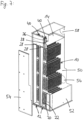
- the Figures 4 and 5 show the clean fluid collection channel 12 with eight filter elements 10, four of which are arranged one behind the other in the longitudinal direction on the first side wall 30 of the clean fluid collection channel 12 in the flow direction of the clean fluid, and four further filter elements 10 of which are arranged one behind the other in the longitudinal direction on the second side wall 32 of the clean fluid collection channel 12 in the flow direction of the clean fluid.
- the clean fluid collection channel 12 is designed such that the filter elements 10 are installed from the raw fluid side and attached to the clean fluid collection channel 12.
- Figure 6 shows an embodiment with two vertically extending clean fluid collection channels 12, which are arranged parallel to each other.
- the illustration in Figure 6 essentially corresponds to that of Figure 5 .
- Figure 6 only the part of the filter elements 10 located to the right of the center of the clean fluid collection channels 12 is shown, whereby it is understood that in reality filter elements 10 open into the clean fluid collection channel 12 in a mirror image from the left side and from the right side.
- Figure 6 The same reference numerals denote the same or similar components or features as in the preceding embodiments. In the following, only differences or special features of the Figure 6 shown embodiment compared to the remaining embodiments and reference is made to the preceding embodiments for the remaining description.
- each filter element 10 is arranged one behind the other on each clean fluid collection channel 12 in the longitudinal direction of the clean fluid collection channel 12, such that the filter elements 10 follow one another in their width direction.
- Figure 6 Three or more filter elements 10 arranged side by side in the direction of their narrow sides lead into the same clean fluid collection channel 12. In the illustration shown with four pairs of filter elements 10 arranged one above the other, 12 filter elements open into each clean fluid collection channel 12. The clean fluid outlet 22 of each filter element 10 opens into the corresponding clean fluid collection channel 12. In Figure 6 Accordingly, twelve clean fluid outlets 22 each open into a respective clean fluid collection channel 12.
- Each clean fluid collection channel 12 has a first, closed end 26 (in Figure 6 below) and an opposite second end forming a clean fluid collection channel outlet 28 (in Figure 6 above).
- the clean fluid collection channel outlets 28, 28 open into a common clean fluid plenum 14.
- a compressed air supply channel 36 with associated compressed air channel outlet 38 is arranged (for the sake of clarity in Figure 6 (provided with reference numerals only for the right-hand clean fluid collection channel 12).
- a pressure pulse can be coupled into the respective clean fluid collection channel 12 via the respective compressed air channel outlet 38, counter to the flow direction of the clean fluid, as already described above.
- each of the compressed air supply channels 36 has a control device 40 with which the compressed air supply channel 36 can be opened or closed.
- the control device 40 is preferably a controllable valve or a controllable flap.
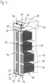
- Figure 7 shows a three-dimensional view of a part of a further embodiment of a filter device according to the invention with twelve filter elements 10 installed on the clean fluid side, which open into a common clean fluid collection channel 12.
- Figure 8 shows a partial view of the Figure 7 filter elements 10 arranged at the lower end of the clean fluid collection channel 12.
- FIG 7 two clean fluid collection channels 12 are shown, into which twelve filter elements 10 are inserted into the corresponding filter element receptacle 42 on the clean fluid side, ie from the side of the clean fluid flowing in the clean fluid collection channel 12
- Each filter element receptacle 42 has an opening 44 formed in the associated wall of the clean fluid collection channel 12, through which opening the respective filter element 10 can be inserted into the raw fluid space 50 of a filter housing 52 surrounding the filter elements 10.
- An annular collar 46 or edge is arranged around each opening 44 and projects approximately orthogonally from the wall of the clean fluid collection channel 12 into the clean fluid collection channel 12. The collar 46 forms the receiving space into which the filter element head 20 of the filter element 10 can be inserted.
- the receiving space is delimited laterally by the inner surface of the collar 46, wherein the inner surface of the collar can cooperate in a sealing manner with the associated outer surface of the filter element head 20, so that no raw fluid or clean fluid can escape through it.
- the outer surface of the filter element head 20 in the exemplary embodiment has a sealing element 48, for example a sealing ring.
- the clean fluid collection channel 12 is designed such that the filter elements 10 are installed from the clean fluid side and inserted into the clean fluid collection channel 12.
- the clean fluid collection channel 12 is arranged adjacent to the filter housing 52, so that a side wall of the clean fluid collection channel 12, which is arranged opposite the filter element receptacles 42, is formed by a housing wall 54.
- the housing wall 54 is, as in Figure 7 shown, in the area opposite the 12 filter element receptacles 42, it is made of a sheet metal and thus forms a door that can be opened or removed in one piece in order to insert the filter elements 10 into the respective associated opening 44 of the filter element receptacle 42 and to fasten the filter element 10 with its filter element head 20 to the clean fluid collection channel 12.
- the housing wall 54 can have a mounting opening (not shown) in order to push the filter element 10 through the mounting opening into the opening 44 of the filter element receptacle 42 and to fasten the filter element 10 with its filter element head 20 to the clean fluid collection channel 12.
- the housing wall 54 can preferably be arranged such that the mounting opening formed therein is opposite the filter element receptacle 42.
- the mounting opening can be closed with a slide, a flap, or a cover so that no clean fluid can escape from the clean fluid collection channel 12 during operation.
- FIG 8 a lower end of the clean fluid collecting channel 12 is made of Figure 7 shown in detail.
- Two filter elements 10 are Figure 8 only partially inserted into the opening 44 of the filter element holder 42 in order to clarify the installation or removal of the filter elements 10 on the clean fluid side.
- the filter element head 20 is then received in the receiving space of the filter element holder 42 and lies sealingly against the respective collar 46.
- Figure 9 shows in its sub-figures 9a), 9b) and 9c different spatial orientations of the filter device 2 according to the invention and additionally schematically a raw fluid side and a clean fluid side installation of the filter elements 10 in the spatially differently aligned clean fluid collection channel 12.
- the filter body of the filter elements 10 projects into the raw fluid space 50.
- Figure 9a shows the clean fluid collection channel 12 in a horizontal orientation.
- the filter elements 10 are arranged suspended in the clean fluid collection channel 12, with the left filter element 10 inserted into the clean fluid collection channel 12 on the raw fluid side and the right filter element 10 inserted into the clean fluid collection channel 12 on the clean fluid side.
- the compressed air supply channel outlet 38 is arranged to the right of the clean fluid collection channel 12 near the clean fluid collection channel outlet 28, where the clean fluid leaves the clean fluid collection channel 12 during normal operation.
- Figure 9b shows the clean fluid collection channel 12 in a vertical orientation.
- the filter elements 10 are arranged orthogonally to the vertical orientation of the clean fluid collection channel 12, so that the longitudinal direction of the filter elements 10 extends horizontally.
- the upper filter element 10 is inserted into the clean fluid collection channel 12 on the raw fluid side, and the lower filter element 10 is inserted into the clean fluid collection channel 12 on the clean fluid side.
- the compressed air supply channel outlet 38 is arranged below, opposite the clean fluid collection channel outlet 28 of the clean fluid collection channel 12.
- Figure 9c shows the clean fluid collection channel 12 in a vertical orientation.
- the filter elements 10 are arranged orthogonally to the vertical orientation of the clean fluid collection channel 12.
- the lower filter element 10 is inserted into the clean fluid collection channel 12 on the raw fluid side, and the upper filter element 10 is inserted into the clean fluid collection channel 12 on the clean fluid side.
- the compressed air supply channel outlet 38 is arranged above, opposite the clean fluid collection channel outlet 28 of the clean fluid collection channel 12.
- the filter device 2 further comprises a filter housing 52, which surrounds the filter elements 10 and the clean fluid collection channel 12 or channels 12.
- the filter housing 52 has a raw fluid inlet 56 to guide raw fluid into the raw fluid chamber 50 and to the filter elements 10. The The supplied raw fluid is then filtered through the filter elements 10 and discharged as clean fluid from the filter device 2 and via a clean fluid outlet 58 in the filter housing 52.
- the clean fluid collection channels 12 are arranged such that the clean fluid collection channel outlets 28 point downwards in the figures. This is an exemplary installation situation and should not be considered as a limitation for the use of the filter device 2 according to the invention.
- the clean fluid collection channel outlet 28 can just as well point upwards, as in the Figures 6 to 8 shown, or point to the side.
Landscapes
- Chemical & Material Sciences (AREA)
- Chemical Kinetics & Catalysis (AREA)
- Physics & Mathematics (AREA)
- Geometry (AREA)
- Filtering Of Dispersed Particles In Gases (AREA)
- Filtration Of Liquid (AREA)
Applications Claiming Priority (2)
| Application Number | Priority Date | Filing Date | Title |
|---|---|---|---|
| DE102019127751.5A DE102019127751A1 (de) | 2019-10-15 | 2019-10-15 | Filtervorrichtung und Verfahren zum Abreinigen eines Filterelements einer Filtervorrichtung |
| PCT/EP2020/078767 WO2021074143A1 (de) | 2019-10-15 | 2020-10-13 | Filtervorrichtung und verfahren zum abreinigen eines filterelements einer filtervorrichtung |
Publications (3)
| Publication Number | Publication Date |
|---|---|
| EP4045169A1 EP4045169A1 (de) | 2022-08-24 |
| EP4045169B1 true EP4045169B1 (de) | 2025-06-25 |
| EP4045169C0 EP4045169C0 (de) | 2025-06-25 |
Family
ID=72852677
Family Applications (1)
| Application Number | Title | Priority Date | Filing Date |
|---|---|---|---|
| EP20790292.5A Active EP4045169B1 (de) | 2019-10-15 | 2020-10-13 | Filtervorrichtung und verfahren zum abreinigen eines filterelements einer filtervorrichtung |
Country Status (7)
| Country | Link |
|---|---|
| US (1) | US12383856B2 (pl) |
| EP (1) | EP4045169B1 (pl) |
| JP (1) | JP7481438B2 (pl) |
| CN (1) | CN114765963A (pl) |
| DE (1) | DE102019127751A1 (pl) |
| PL (1) | PL4045169T3 (pl) |
| WO (1) | WO2021074143A1 (pl) |
Families Citing this family (3)
| Publication number | Priority date | Publication date | Assignee | Title |
|---|---|---|---|---|
| EP4028144B1 (en) | 2019-09-13 | 2025-08-13 | Donaldson Company, Inc. | Air filter systems, filter bag assemblies, filter bags |
| EP4308270B1 (en) | 2021-03-16 | 2024-06-26 | Donaldson Company, Inc. | Foldable filter bags, filter bag support assemblies, and filter bag assemblies |
| JP2025529449A (ja) * | 2022-09-14 | 2025-09-04 | ドナルドソン カンパニー,インコーポレイティド | 傾斜開口部を備えたフィルタ及びフィルタ組立体、捕集装置、並びに使用方法 |
Family Cites Families (24)
| Publication number | Priority date | Publication date | Assignee | Title |
|---|---|---|---|---|
| DE372967C (de) * | 1922-04-11 | 1923-04-06 | Theodor Hansen | Staubfilteranlage, in der die Staubluft durch eine zwischen Filtergehaeuse und Staubluftleitung eingeschaltete Saug- oder Druckvorrichtung gedrueckt wird |
| DE903890C (de) | 1950-02-21 | 1954-02-11 | Heinrich Luehr | Mehrkammer-Filteranlage |
| JPS589687B2 (ja) * | 1976-02-25 | 1983-02-22 | 株式会社日立製作所 | フイルタ−の再生方法 |
| US4161389A (en) * | 1978-04-07 | 1979-07-17 | Procedyne, Inc. | Fluidized bed calcining system |
| GB2162768B (en) * | 1984-08-06 | 1989-01-11 | Tilghman Wheelabrator Ltd | Filtering apparatus |
| JPH061205Y2 (ja) * | 1988-03-02 | 1994-01-12 | 石垣機工株式会社 | ▲ろ▼過機の▲ろ▼材 |
| US5944859A (en) * | 1996-05-06 | 1999-08-31 | Siemens Westinghouse Power Corporation | Hot gas filter and system assembly |
| US5938818A (en) * | 1997-08-22 | 1999-08-17 | Energy & Environmental Research Center Foundation | Advanced hybrid particulate collector and method of operation |
| US6077490A (en) | 1999-03-18 | 2000-06-20 | Mcdermott Technology, Inc. | Method and apparatus for filtering hot syngas |
| DE19917165C2 (de) * | 1999-04-16 | 2001-02-08 | Karlsruhe Forschzent | Verfahren zum Abreinigen von rohrförmigen Filterelementen und Vorrichtung zur Ausübung des Verfahrens |
| EP1178858B1 (en) * | 1999-05-21 | 2004-10-06 | Shell Internationale Researchmaatschappij B.V. | Apparatus and process for removing solid particles from gases |
| DE60326620D1 (de) * | 2002-10-22 | 2009-04-23 | Polymer Group Inc | Wasserstrahlverfestigte filtermedien mit verbesserter statischer ableitung und verfahren |
| DE102005013711B4 (de) | 2005-03-24 | 2022-07-28 | Dürr Systems Ag | Anlage zum Lackieren von Gegenständen |
| DE102006048883A1 (de) | 2006-10-17 | 2008-04-24 | Forschungszentrum Karlsruhe Gmbh | Filtersystem mit Abgasreinigungsvorrichtung |
| US20090114095A1 (en) * | 2007-11-06 | 2009-05-07 | General Electric Company | Filter cleaning system and method |
| JP5427402B2 (ja) * | 2008-12-22 | 2014-02-26 | 三菱重工業株式会社 | フィルタの逆洗装置 |
| US8157878B2 (en) * | 2009-10-08 | 2012-04-17 | Mac Process Llc | Air distribution arrangement for a dust collector system |
| EP2550081A4 (en) * | 2010-03-25 | 2013-08-14 | Mpc Inc | FILTER ARRANGEMENT |
| EP2633894B1 (en) * | 2012-02-28 | 2016-04-27 | Pall Corporation | Hot gas filtration system and process for regenerating said system |
| ITMI20120952A1 (it) * | 2012-06-01 | 2013-12-02 | Ecospray Technologies S R L | Apparato filtrante anti-particolato per motori diesel marini e metodo di funzionamento e rigenerazione di detto apparato |
| US9028578B2 (en) * | 2013-02-28 | 2015-05-12 | Bha Altair, Llc | Gas turbine inlet filter with replaceable media cartridges |
| DE202017104480U1 (de) * | 2017-07-27 | 2017-08-14 | Herding Gmbh Filtertechnik | Filtervorrichtung |
| JP6374133B1 (ja) * | 2018-05-17 | 2018-08-15 | 曜一 堀 | フィルター漏れ監視装置及びそれを備えた粒子分離機 |
| US10625194B1 (en) * | 2018-12-28 | 2020-04-21 | Schenck Process Llc | Filter cartridges with tubular filter members |
-
2019
- 2019-10-15 DE DE102019127751.5A patent/DE102019127751A1/de active Pending
-
2020
- 2020-10-13 EP EP20790292.5A patent/EP4045169B1/de active Active
- 2020-10-13 CN CN202080084083.0A patent/CN114765963A/zh active Pending
- 2020-10-13 US US17/769,063 patent/US12383856B2/en active Active
- 2020-10-13 JP JP2022522960A patent/JP7481438B2/ja active Active
- 2020-10-13 PL PL20790292.5T patent/PL4045169T3/pl unknown
- 2020-10-13 WO PCT/EP2020/078767 patent/WO2021074143A1/de not_active Ceased
Also Published As
| Publication number | Publication date |
|---|---|
| US20240100465A1 (en) | 2024-03-28 |
| JP7481438B2 (ja) | 2024-05-10 |
| WO2021074143A1 (de) | 2021-04-22 |
| DE102019127751A1 (de) | 2021-04-15 |
| EP4045169C0 (de) | 2025-06-25 |
| CN114765963A (zh) | 2022-07-19 |
| US12383856B2 (en) | 2025-08-12 |
| JP2023501887A (ja) | 2023-01-20 |
| PL4045169T3 (pl) | 2025-11-12 |
| EP4045169A1 (de) | 2022-08-24 |
Similar Documents
| Publication | Publication Date | Title |
|---|---|---|
| DE4425765C2 (de) | Anlage zum Reinigen von Werkstücken mittels eines Druckluftstrahles | |
| EP4045169B1 (de) | Filtervorrichtung und verfahren zum abreinigen eines filterelements einer filtervorrichtung | |
| EP2773440B2 (de) | Anlage mit einer vorrichtung zum abscheiden von overspray | |
| EP2822701B1 (de) | Verfahren und vorrichtung zum abführen von mit overspray beladener prozessluft sowie anlage zum beschichten von gegenständen | |
| EP3765170B1 (de) | Abscheideeinheit mit abschlagfäche | |
| DE102018103019A1 (de) | Vorrichtung zum Abscheiden von Overspray | |
| EP0781585A1 (de) | Einrichtung zum Entstauben von Gas sowie Verfahren zum Reinigen mindestens eines Filters der Einrichtung | |
| EP1034023A1 (de) | Verfahren zur reinigung von filterkerzen eines kerzenfilters | |
| EP3017854A1 (de) | Hohlfilterelement eines filters zur filtrierung von fluid, filter, filtergehäuse und dichtung eines hohlfilterelements | |
| DE112017006479T5 (de) | Ein Staubsammler für gasförmige Fluide und Verfahren zur Herstellung des Staubsammlers | |
| DE20321726U1 (de) | Vorrichtung zur Beseitigung von Luftverunreinigungen in einer Nasslackieranlage | |
| EP4267313A1 (de) | Filtermodul und verwendung eines filtermoduls zur abscheidung von lack- und/oder farbresten, insbesondere von overspray in einer lackierkabine | |
| EP3730022B1 (de) | Filterelement | |
| WO2020143962A1 (de) | Filtersystem zur aufreinigung von einem mit partikeln beladenen gasstrom und anordnung zur aufreinigung von einem mit partikeln beladenen gasstrom eines fluidisierungsapparates mittels eines filtersystems | |
| DE69522153T2 (de) | Staubsammelapparat | |
| CH712504A2 (de) | Gehäuse für ein Laborgerät. | |
| DE10125732B4 (de) | Filter zum Entstauben von ein partikelförmiges Gut enthaltende Prozeßluft in einer Prozeßapparatur sowie derartige Prozeßapparatur | |
| DE3632405A1 (de) | Filter fuer farbspritz- und einbrennkabinen | |
| EP1563889B1 (de) | Filternder Abscheider für partikelbelastete Gase | |
| DE102021005289A1 (de) | Filtervorrichtung | |
| EP1495792A1 (de) | Filtertasche für einen Abgasfilter | |
| DE102016121779B4 (de) | Filteranlage mit Reinigungsluftleiteinrichtung für horizontale Filterpatronen | |
| EP3219396A1 (de) | Lackieranlage und verfahren zum lackieren eines werkstücks sowie filterelement hierfür | |
| DE19651857C1 (de) | Vorrichtung zur Abscheidung von Feststoffen aus staubbeladenen Abgasen, insbesondere von Verbrennungsanlagen | |
| AT528038B1 (de) | Aerosolfilter |
Legal Events
| Date | Code | Title | Description |
|---|---|---|---|
| STAA | Information on the status of an ep patent application or granted ep patent |
Free format text: STATUS: UNKNOWN |
|
| STAA | Information on the status of an ep patent application or granted ep patent |
Free format text: STATUS: THE INTERNATIONAL PUBLICATION HAS BEEN MADE |
|
| PUAI | Public reference made under article 153(3) epc to a published international application that has entered the european phase |
Free format text: ORIGINAL CODE: 0009012 |
|
| STAA | Information on the status of an ep patent application or granted ep patent |
Free format text: STATUS: REQUEST FOR EXAMINATION WAS MADE |
|
| 17P | Request for examination filed |
Effective date: 20220426 |
|
| AK | Designated contracting states |
Kind code of ref document: A1 Designated state(s): AL AT BE BG CH CY CZ DE DK EE ES FI FR GB GR HR HU IE IS IT LI LT LU LV MC MK MT NL NO PL PT RO RS SE SI SK SM TR |
|
| DAV | Request for validation of the european patent (deleted) | ||
| DAX | Request for extension of the european patent (deleted) | ||
| STAA | Information on the status of an ep patent application or granted ep patent |
Free format text: STATUS: EXAMINATION IS IN PROGRESS |
|
| 17Q | First examination report despatched |
Effective date: 20230719 |
|
| GRAP | Despatch of communication of intention to grant a patent |
Free format text: ORIGINAL CODE: EPIDOSNIGR1 |
|
| STAA | Information on the status of an ep patent application or granted ep patent |
Free format text: STATUS: GRANT OF PATENT IS INTENDED |
|
| INTG | Intention to grant announced |
Effective date: 20250206 |
|
| GRAS | Grant fee paid |
Free format text: ORIGINAL CODE: EPIDOSNIGR3 |
|
| GRAA | (expected) grant |
Free format text: ORIGINAL CODE: 0009210 |
|
| STAA | Information on the status of an ep patent application or granted ep patent |
Free format text: STATUS: THE PATENT HAS BEEN GRANTED |
|
| AK | Designated contracting states |
Kind code of ref document: B1 Designated state(s): AL AT BE BG CH CY CZ DE DK EE ES FI FR GB GR HR HU IE IS IT LI LT LU LV MC MK MT NL NO PL PT RO RS SE SI SK SM TR |
|
| REG | Reference to a national code |
Ref country code: GB Ref legal event code: FG4D Free format text: NOT ENGLISH |
|
| REG | Reference to a national code |
Ref country code: CH Ref legal event code: EP |
|
| REG | Reference to a national code |
Ref country code: CH Ref legal event code: EP |
|
| REG | Reference to a national code |
Ref country code: IE Ref legal event code: FG4D Free format text: LANGUAGE OF EP DOCUMENT: GERMAN |
|
| U01 | Request for unitary effect filed |
Effective date: 20250630 |
|
| U07 | Unitary effect registered |
Designated state(s): AT BE BG DE DK EE FI FR IT LT LU LV MT NL PT RO SE SI Effective date: 20250704 |
|
| PG25 | Lapsed in a contracting state [announced via postgrant information from national office to epo] |
Ref country code: NO Free format text: LAPSE BECAUSE OF FAILURE TO SUBMIT A TRANSLATION OF THE DESCRIPTION OR TO PAY THE FEE WITHIN THE PRESCRIBED TIME-LIMIT Effective date: 20250925 Ref country code: GR Free format text: LAPSE BECAUSE OF FAILURE TO SUBMIT A TRANSLATION OF THE DESCRIPTION OR TO PAY THE FEE WITHIN THE PRESCRIBED TIME-LIMIT Effective date: 20250926 |
|
| PG25 | Lapsed in a contracting state [announced via postgrant information from national office to epo] |
Ref country code: HR Free format text: LAPSE BECAUSE OF FAILURE TO SUBMIT A TRANSLATION OF THE DESCRIPTION OR TO PAY THE FEE WITHIN THE PRESCRIBED TIME-LIMIT Effective date: 20250625 |
|
| PG25 | Lapsed in a contracting state [announced via postgrant information from national office to epo] |
Ref country code: RS Free format text: LAPSE BECAUSE OF FAILURE TO SUBMIT A TRANSLATION OF THE DESCRIPTION OR TO PAY THE FEE WITHIN THE PRESCRIBED TIME-LIMIT Effective date: 20250925 |
|
| REG | Reference to a national code |
Ref country code: CH Ref legal event code: U11 Free format text: ST27 STATUS EVENT CODE: U-0-0-U10-U11 (AS PROVIDED BY THE NATIONAL OFFICE) Effective date: 20251101 |
|
| U20 | Renewal fee for the european patent with unitary effect paid |
Year of fee payment: 6 Effective date: 20251029 |
|
| PG25 | Lapsed in a contracting state [announced via postgrant information from national office to epo] |
Ref country code: IS Free format text: LAPSE BECAUSE OF FAILURE TO SUBMIT A TRANSLATION OF THE DESCRIPTION OR TO PAY THE FEE WITHIN THE PRESCRIBED TIME-LIMIT Effective date: 20251025 |
|
| PGFP | Annual fee paid to national office [announced via postgrant information from national office to epo] |
Ref country code: GB Payment date: 20251024 Year of fee payment: 6 |
|
| PG25 | Lapsed in a contracting state [announced via postgrant information from national office to epo] |
Ref country code: SM Free format text: LAPSE BECAUSE OF FAILURE TO SUBMIT A TRANSLATION OF THE DESCRIPTION OR TO PAY THE FEE WITHIN THE PRESCRIBED TIME-LIMIT Effective date: 20250625 |
|
| PGFP | Annual fee paid to national office [announced via postgrant information from national office to epo] |
Ref country code: CH Payment date: 20251101 Year of fee payment: 6 |
|
| PG25 | Lapsed in a contracting state [announced via postgrant information from national office to epo] |
Ref country code: CZ Free format text: LAPSE BECAUSE OF FAILURE TO SUBMIT A TRANSLATION OF THE DESCRIPTION OR TO PAY THE FEE WITHIN THE PRESCRIBED TIME-LIMIT Effective date: 20250625 |
|
| PGFP | Annual fee paid to national office [announced via postgrant information from national office to epo] |
Ref country code: PL Payment date: 20251003 Year of fee payment: 6 |
|
| PG25 | Lapsed in a contracting state [announced via postgrant information from national office to epo] |
Ref country code: SK Free format text: LAPSE BECAUSE OF FAILURE TO SUBMIT A TRANSLATION OF THE DESCRIPTION OR TO PAY THE FEE WITHIN THE PRESCRIBED TIME-LIMIT Effective date: 20250625 |
|
| PG25 | Lapsed in a contracting state [announced via postgrant information from national office to epo] |
Ref country code: ES Free format text: LAPSE BECAUSE OF FAILURE TO SUBMIT A TRANSLATION OF THE DESCRIPTION OR TO PAY THE FEE WITHIN THE PRESCRIBED TIME-LIMIT Effective date: 20250625 |
|
| REG | Reference to a national code |
Ref country code: CH Ref legal event code: R18 Free format text: ST27 STATUS EVENT CODE: U-0-0-R10-R18 (AS PROVIDED BY THE NATIONAL OFFICE) Effective date: 20260211 |