EP4045832B1 - Zahnscheibe - Google Patents
Zahnscheibe Download PDFInfo
- Publication number
- EP4045832B1 EP4045832B1 EP20792967.0A EP20792967A EP4045832B1 EP 4045832 B1 EP4045832 B1 EP 4045832B1 EP 20792967 A EP20792967 A EP 20792967A EP 4045832 B1 EP4045832 B1 EP 4045832B1
- Authority
- EP
- European Patent Office
- Prior art keywords
- cutting
- support
- toothed washer
- teeth
- areas
- Prior art date
- Legal status (The legal status is an assumption and is not a legal conclusion. Google has not performed a legal analysis and makes no representation as to the accuracy of the status listed.)
- Active
Links
Images




Classifications
-
- F—MECHANICAL ENGINEERING; LIGHTING; HEATING; WEAPONS; BLASTING
- F16—ENGINEERING ELEMENTS AND UNITS; GENERAL MEASURES FOR PRODUCING AND MAINTAINING EFFECTIVE FUNCTIONING OF MACHINES OR INSTALLATIONS; THERMAL INSULATION IN GENERAL
- F16L—PIPES; JOINTS OR FITTINGS FOR PIPES; SUPPORTS FOR PIPES, CABLES OR PROTECTIVE TUBING; MEANS FOR THERMAL INSULATION IN GENERAL
- F16L21/00—Joints with sleeve or socket
- F16L21/08—Joints with sleeve or socket with additional locking means
-
- F—MECHANICAL ENGINEERING; LIGHTING; HEATING; WEAPONS; BLASTING
- F16—ENGINEERING ELEMENTS AND UNITS; GENERAL MEASURES FOR PRODUCING AND MAINTAINING EFFECTIVE FUNCTIONING OF MACHINES OR INSTALLATIONS; THERMAL INSULATION IN GENERAL
- F16L—PIPES; JOINTS OR FITTINGS FOR PIPES; SUPPORTS FOR PIPES, CABLES OR PROTECTIVE TUBING; MEANS FOR THERMAL INSULATION IN GENERAL
- F16L37/00—Couplings of the quick-acting type
- F16L37/08—Couplings of the quick-acting type in which the connection between abutting or axially overlapping ends is maintained by locking members
- F16L37/084—Couplings of the quick-acting type in which the connection between abutting or axially overlapping ends is maintained by locking members combined with automatic locking
- F16L37/091—Couplings of the quick-acting type in which the connection between abutting or axially overlapping ends is maintained by locking members combined with automatic locking by means of a ring provided with teeth or fingers
Definitions
- the invention relates to a toothed disk, in particular for fixing a pipeline inserted in a fluid connector in an insertion direction, having an annular base with a toothed disk central axis, wherein cutting teeth are arranged on the inner circumference of the base via a molded-on spring-elastic bending joint section and an adjoining molded-on holding section, running radially inwards and obliquely to the toothed disk central axis and in the insertion direction, in one piece on the base, wherein the cutting teeth are designed in such a way that they cut into an outer circumference of the pipeline when the pipeline moves against the insertion direction, wherein the cutting teeth have a cutting surface for cutting into the outer circumference of the pipeline to be fixed.
- the cutting teeth have a support surface. It is provided that the support surface is designed to be set back radially outwards when viewed from the cutting surface, so that the cutting of the respective cutting tooth is limited when the support surface is in contact with the outer circumference of the pipeline. Furthermore, the invention relates to a fluid connector for pipe assembly, in particular fluid-carrying pipes, having a receiving section for introducing a pipe in an insertion direction, as well as a holding element arranged in the receiving section.
- a toothed disk for fixing a pipeline in a fluid connector is known.
- the toothed disk has an annular base with evenly distributed cutting teeth all around, which extend radially inwards and at an angle to a toothed disk center axis.
- the cutting teeth each have a support surface, which is set back radially from a cutting surface of the cutting teeth to the outside in relation to the toothed disk center axis.
- a toothed disk which has a support surface between a cutting tooth and a holding section, which is connected in one piece to the cutting tooth and the holding section.
- the support surface is connected in one piece to the holding section and the cutting tooth via a bend.
- the support surface is designed in such a way that the support surface encloses a support angle with the base in a direction facing away from a toothed disk center axis, which is smaller than a bending angle that the holding section encloses with the base in the direction facing away from the toothed disk center axis.
- a connecting disc is made of DE 603 03 013 T2
- the connecting disc has specially shaped teeth.
- the shape of the teeth makes it possible to create a large contact area between the respective tooth and the pipe.
- the connecting disc also has claw tips, which are formed by a rounded edge of the teeth towards the central axis of the tooth disc.
- a toothed disc which has material cutouts in order to increase the spring elasticity of the cutting teeth and reduce the necessary insertion forces when assembling a pipeline. So that the toothed disc can generate high holding forces, the cutting teeth have a cutting edge that is constantly shaped across the width of the cutting teeth. In this case, a wrap angle for the pipeline of at least 70%, in particular of 75% to 95%, should preferably be maintained in order to ensure functionality.
- the pipeline When assembling the pipeline, the pipeline is inserted through the ring-shaped base along the toothed disk center axis in an insertion direction.
- the cutting teeth of the toothed disk are designed to run diagonally to the toothed disk center axis in the insertion direction.
- the cutting teeth form a cutting angle with the base in a direction facing away from the toothed disk center axis.
- the cutting teeth are designed to run diagonally to the base in the insertion direction in such a way that that the cutting angle is in particular greater than 90° and preferably less than or equal to 180°.
- the cutting teeth When the pipeline is inserted, the cutting teeth are bent radially away from the toothed disk center axis. The final assembly position is reached when the pipeline is inserted into the fluid connector as far as it will go. Due to a restoring force of the spring-elastic bending joints and a system pressure load on the pipeline, the pipeline is moved in a fixing movement against the original insertion direction so that the cutting teeth cut into the outer circumference of the pipeline. Due to the fixing movement of the pipeline in conjunction with the cutting of the cutting teeth, the cutting angle of the cutting teeth increases during the fixing movement, i.e. the cutting teeth steadily tend towards a position perpendicular to the toothed disk center axis as the fixing movement increases. As a result, the cutting teeth cut deeper into the pipeline as the fixing movement of the pipeline increases.
- the pipe is cut off or torn off if, in the assembled state, the cutting teeth are at too great a cutting angle due to an uncontrolled fixing movement due to excessive system pressure or a tensile load on the pipeline itself and thus cut too deeply into the outer circumference of the pipeline.
- the pipeline is weakened to such an extent that the pipeline can no longer withstand the system pressure or a tensile load on the pipeline itself, so that the pipeline tears off.
- the pipeline peels off if, during the fixing movement and/or in an assembled state, the cutting teeth are at too shallow a cutting angle. The result of this is that the pipeline is not sufficiently fixed to withstand a loosening force and the outer circumference of the pipeline is simply peeled off during the fixing movement and the pipeline does not assume a fixed installation position.
- the invention is based on the object of providing a toothed disk which overcomes the problems known from the prior art, in particular by improving the cutting behavior of the cutting teeth at least by preventing twisting and tilting of the toothed disk.
- the cutting teeth have a support surface, and the support surface is designed to be set back radially outwards when viewed from the cutting surface, so that the cutting of the respective cutting tooth is limited when the support surface is in contact with the outer circumference of the pipeline.
- the annular base has rounded torsion reinforcements formed between two bending joint sections, the vertices of which are aligned pointing towards the toothed disk center axis.
- the design according to the invention advantageously improves the cutting behavior.
- the design of the cutting teeth means that both the cutting angle of the cutting teeth, which increases steadily with increasing fixing movement, and the fixing movement itself can be determined.
- the cutting behavior of the toothed disk can therefore be ideally adapted to the respective pipeline to be installed, in particular with regard to its material, diameter and dimensions.
- the cutting teeth each have at least two teeth on which the cutting surfaces are formed.
- the support surface is preferably formed between the teeth, wherein the cutting surfaces are in particular aligned with the support surfaces.
- the cutting depth of the respective cutting tooth in an assembled and fixed pipe corresponds to the projection. The contact of the support surface on the outer circumference of the pipe thus limits further cutting and prevents further fixing movement.
- the cutting surfaces of the cutting teeth each have a cutting surface and the support surface of the cutting teeth each have a support surface.
- the cutting surface is calculated for each cutting tooth in particular from a cutting width which corresponds to the length of the cutting surfaces perpendicular to the toothed disk center axis, multiplied by the cutting thickness which corresponds to the axial extension of the cutting surfaces to the toothed disk center axis in the area of the cutting surfaces.
- the support surface is calculated for each cutting tooth in particular from a support width which corresponds to the length of the support surfaces perpendicular to the toothed disk center axis, multiplied by the support thickness which corresponds to the axial extension to the toothed disk center axis in the area of the support surfaces.
- the axial extent relative to the toothed disk center axis refers to an undeformed state of the toothed disk.
- the toothed disk is formed in particular in a pressing tool, wherein the cutting teeth in the undeformed state are preferably completely aligned together with the annular base and the spring-elastic bending joint sections in a plane perpendicular to the toothed disk center axis.
- the toothed disk is only bent in the forming process, wherein the cutting thickness and support thickness are preferably retained in the pressing tool after the forming process.
- the cutting surfaces and/or the support surfaces are each designed as partial circle segments bent around a center point and preferably the centers are each aligned with the toothed disk center axis, whereby in particular the centers of the pitch circle segments, preferably in the undeformed state of the toothed disk, lie in the toothed disk center axis.
- the arc length of the cutting surface around the respective pitch circle segment center is advantageously used for the cutting width. Accordingly, the arc length of the support surface around the respective pitch circle segment center is used for the support surface.
- the cutting surfaces each have the cutting thickness which corresponds to the axial extension of the cutting surfaces to the toothed disk center axis in the region of the cutting surfaces
- the support surfaces each have the support thickness which corresponds to the axial extension to the toothed disk center axis in the region of the support surfaces, wherein the support thickness of the support surface is preferably, at least partially, greater than the cutting thickness of the cutting surface.
- the support thickness of the support surface is in particular at least partially twice as large as the cutting thickness of the cutting surface.
- the increased support thickness enlarges the support surface in such a way that when the support surface rests on the outer circumference of the pipeline, the cutting of the respective cutting tooth is made considerably more difficult than with just a support surface set back from the cutting surface in alignment radially to the toothed disk center axis.
- each cutting tooth has a ratio of a sum of the cutting surfaces of the cutting surfaces to a sum of the support surfaces of the support surfaces, which lies in a range of 0.8 to 1.2, in particular 0.9 to 1.1, preferably corresponds to 1.
- the support surface is arranged between the cutting tooth and the holding section, in particular, connected in one piece with the cutting tooth and the holding section.
- the support surface is preferably connected to a first bend in the bending joint section by means of the holding section and to the cutting tooth by a third bend.
- the support surface closes in a direction which is In the direction facing away from the toothed disk center axis, the cutting tooth forms a support angle with the base, which is preferably smaller than a bending angle that the holding section forms with the base in the direction facing away from the toothed disk center axis.
- the cutting tooth forms a cutting angle with the base in the direction facing away from the toothed disk center axis, the cutting angle preferably being larger than the support angle.
- the design of the bending angle sets a lever for the holding section.
- a contact pressure is set between the support surface and the outer circumference of the pipeline.
- the bending angle is preferably selected such that it is in a range between less than or equal to 175° and greater than or equal to 135° in a non-assembled state, because at an angle greater than 175° the cutting teeth would turn axially towards the toothed disk center axis during the fixing movement of the pipeline to be assembled against the insertion direction and cut through the pipeline. On the other hand, at a bending angle of less than 135° the radial clamping force would be too low and the pipeline to be assembled would peel off.
- the pipeline is secured in particular at two positions on the outer circumference that are axially offset to the toothed disk center axis.
- the toothed disk preferably creates a force-form connection by cutting the cutting surfaces in a cutting plane into the outer circumference of the pipeline.
- the advantageous angling of the individual sections during the fixing movement and the resulting tendency of the cutting tooth to increase the cutting angle creates a contact pressure between the support surface and the outer circumference of the pipe that is directed radially to the toothed disk center axis.
- This force connection is evenly distributed in particular over the circumference of the outer pipe in a press plane that is axially offset from the cutting plane in the direction of the fixing movement to the toothed disk center axis and aligned parallel to the cutting plane.
- the toothed disk is preferably formed in a pressing tool, wherein the cutting surfaces in an undeformed state of the toothed disk have an inner initial circumference which is smaller than an inner circumference of the pipeline to be fixed.
- the bending angle of the finished toothed disk and the lengths of the support surface, the cutting tooth and the holding section are preferably selected such that, assuming that the support surface and the cutting tooth are each connected to the holding section in a straight line, the cutting surfaces of the cutting teeth lie in an inner intermediate circumference which would lead to the pipeline being cut off or torn off, in particular under a system pressure load.
- a fluid connector for pipe assembly in particular fluid-carrying pipes, having a receiving section for introducing a pipe in an insertion direction, and a holding element arranged in the receiving section, in that the holding element is designed as a toothed disk with the features according to one of claims 1 to 10.
- the Figures 1 to 8 show variants of a toothed disc 1 not according to the invention.
- a toothed disk 1 having an annular base 2 with a toothed disk center axis X.
- Such toothed disks 1 are preferably used to fix a fluid connector 4 in a Figures 2 , 8 and 10 shown, insertion direction E inserted pipe 6.
- the fluid connector 4 with inserted pipe 6 is in Figure 15 shown.
- cutting teeth 12 are arranged in one piece on the base 2 radially inwards and obliquely to the toothed disk center axis X, wherein the cutting teeth 12 run in the insertion direction E. Furthermore, the cutting teeth 12 are designed in such a way that they can be moved in a fixing movement F of the pipe 6, as shown in the Figures 3a to 6a and 11 to 14 shown, cut into an outer circumference 14 of the pipe 6 against the insertion direction E. For this purpose, the cutting teeth 12 have a cutting surface 16 for cutting into the outer circumference 14 of the pipe 6 to be fixed.
- This Cutting angle ⁇ 1, ⁇ 2, ⁇ 3, see Figures 2 , 8 and 10 is in particular 120° to 150°, preferably 130° to 140°.
- the cutting teeth 12 are evenly distributed over the circumference of the ring-shaped base 2.
- the cutting teeth 12 each form a wrap angle with their cutting surfaces 16, i.e. an angle section in which the respective cutting tooth 12 cuts into the outer circumference 14 of the pipeline 6 to be fixed.
- the cutting teeth 12 together have a circumferential wrap angle of at least 70%, in particular from 75% to 95% of the circumference of the pipeline 6.
- the cutting teeth 12 have a support surface 18 and the support surface 18 is designed to be set back radially outwards from the cutting surface 16, starting from the toothed disk center axis X. This limits the cutting of the respective cutting tooth 12 when the support surface 18 is in contact with the outer circumference 14 of the pipeline 6.
- the cutting behavior is advantageously improved by the aforementioned design.
- the design of the cutting teeth 12 means that both the cutting angle ⁇ 1, ⁇ 2, ⁇ 3 of the cutting teeth 12, which increases steadily with increasing fixing movement F, and the fixing movement F itself can be determined. This means that the penetration depth of the cutting teeth 12 into the pipe 6 is limited and a cutting angle, which the cutting teeth 12 enclose with the outer circumference 14 of the pipe 6, can be set. Peeling or cutting or tearing when fixing a pipe 6 is thereby effectively prevented.
- the cutting behavior of the toothed disk 1 can thus be ideally adapted to the respective pipe 6 to be installed, in particular with regard to its material, diameter and dimensions.
- the cutting surfaces 16 and/or the support surfaces 18 are each designed as partial circle segments 20 bent around a center point.
- the centers are in particular aligned with the toothed disk center axis X, wherein preferably the centers of the partial circle segments 20, preferably in the undeformed state of the toothed disk, lie in the toothed disk center axis X.
- the Figures 1 , 9a and 9b This advantageous design is shown.
- the formation of the partial circle segments advantageously achieves uniform cutting.
- the cutting teeth 12 each have at least two teeth 13.
- the cutting surface 16 is formed on these teeth 13, with the support surface 18 preferably being formed between the teeth 13.
- the cutting surfaces 16 of these designs are preferably formed in alignment with the support surfaces 18.
- the assembly process in the Figures 3 to 6 shows limits the cutting of the respective cutting tooth 12. Due to the fact that the cutting surfaces 16 are designed in particular to be flush with the support surfaces 18 and the support surface 18 is simultaneously designed to be set back radially outwards from the cutting surface 16, a cutting depth can be set in a simple manner by means of a resulting projection U of the cutting surface 16 to the support surface 18.
- the projection U is in Figure 2 shown.
- the cutting depth of the respective cutting tooth 12 preferably corresponds to the projection U.
- the support surfaces 18 also penetrate into the outer circumference 14 of the pipe 6 to be mounted in order to increase the wrap angle and to achieve additional axial fixation of the pipe 6. The contact of the support surface 18 with the outer circumference 14 of the pipe 6 thus limits further cutting and hinders a further fixing movement F.
- the support surface 18 is blunt; in particular, the support surface is embossed bluntly during the manufacturing process so that it can cut less or only weakly into the outer circumference 14 of the pipeline 6 to be mounted.
- the toothed disk 1 is shown in a state without any contact with the pipeline 6 to be mounted.
- the toothed disk 1 has a cutting angle of 120° to 150°, preferably 130° to 140°, wherein the cutting surfaces 16 of the cutting teeth 12 are arranged in an inner circular path which has a smaller diameter than the outer circumference 14 of the pipeline 6 to be mounted.
- FIGS. 6a and 6b show a preferred embodiment in which, via the first contact of the support surface 18 on the outer circumference 14 of the pipeline 6, the support surface 18 itself cuts into the outer circumference 14 of the pipeline 6 in addition to the cutting surface 16 and supports the pipeline 6 axially to the toothed disk center axis X.
- each cutting tooth 12 has a cutting surface and the support surface 18 of the cutting teeth 12 each have a support surface.
- each cutting tooth 12 has a ratio of a sum of the cutting surfaces of the cutting surfaces 16 to a sum of the support surfaces of the support surfaces 18, which is in a range of 0.8 to 1.2, in particular 0.9 to 1.1 or preferably corresponds to 1.
- the cutting surface is calculated for each cutting tooth 12 in particular from a cutting width S, see Figure 1 , which corresponds to the length of the cutting surfaces 16 perpendicular to the toothed disk center axis X, multiplied by the cutting thickness D1, see Figure 2 , which corresponds to the axial extension of the cutting surfaces 16 to the toothed disk center axis X in the region of the cutting surfaces 16.
- the support surface is calculated for each cutting tooth 12 in particular from a support width B, which corresponds to the length of the support surfaces 18 perpendicular to the toothed disk center axis X, multiplied by the support thickness D2, which corresponds to the axial extension to the toothed disk center axis X in the region of the support surfaces 18.
- the axial extension relative to the toothed disk center axis X refers to an undeformed state of the toothed disk 1.
- the cutting teeth 12 are preferably completely aligned together with the annular base 2 and the spring-elastic bending joint sections 8 in a plane perpendicular to the toothed disk center axis X.
- the cutting thickness D1 and the support thickness D2 are retained after the forming process.
- the cutting surfaces 16 and/or the support surfaces 18 are each designed as partial circle segments 20 bent around a center point, according to the Figure 1 illustrated embodiment, and preferably the centers are each aligned with the toothed disk center axis X, wherein in particular the centers of the pitch circle segments 20, preferably in the undeformed state, lie in the toothed disk center axis X, the arc length of the cutting surface 16 around the respective pitch circle segment center is advantageously used for the cutting width S. Accordingly, for the support width B of the support surface 18, in particular the arc length of the support surface 18 around the respective pitch circle segment center is used.
- the cutting surfaces 16 of the toothed disk 1 are in accordance with the Figures 7 and 8
- the cutting thickness D1 is advantageous, see Figure 8 , which corresponds to the axial extension of the cutting surfaces 16 to the toothed disk center axis X in the area of the cutting surfaces 16, and the support surfaces 18 each have in particular the Figure 8 shown support thickness D2, which corresponds to the axial extension in the area of the support surfaces 18.
- the support thickness D2 of the support surface 18 is preferably at least partially larger than the cutting thickness D1 of the cutting surface 16.
- Figure 8 is particularly suitable in Figure 8 recognizable, whereby Figure 8 a particularly preferred embodiment is shown, according to which the support thickness D2 of the support surface 18 is in particular at least partially twice as large as the cutting thickness D1 of the cutting surface 16.
- the Figures 8 and 7 show that the increased support thickness D2 can be produced during the manufacturing process of the toothed disk 1 by simply folding a tongue connected to the cutting tooth 12.
- the assembly process is in accordance with the Figures 3a to 6b on the Figures 7 and 8 illustrated embodiment of the invention, wherein the limiting effect of the recessed support surface 18 on the cutting of the respective cutting tooth 12 is increased by the enlarged support surface 18.
- FIGs 9a to 14 Further alternative designs of the toothed disc 1 are shown.
- the design in Figure 9b illustrated embodiment by a reinforced support area 30, in which at least the support surface 18 is arranged, and in the number of cutting teeth 12 from that in Figure 9a
- These designs are characterized in contrast to the toothed disc 1 according to the Figure 1 or 7
- the embodiment shown in the drawing is characterized by a different arrangement of the support surface 18, whereby the Figures 9 to 14 shown versions in addition to the previously mentioned versions according to the Figures 1 to 8 can be combined and supplemented.
- the Figures 10 to 14 a section along DD according to Figure 9a However, the advantageous embodiments described below are limited to the design in Figure 9b transferable.
- the number of cutting teeth is adapted to the desired insertion behavior.
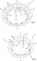
- the toothed disk 1 can be suitably adjusted according to the Figure 9a In the embodiment shown, ten cutting teeth 12 have been formed. According to a further advantageous embodiment, the toothed disk 1 can be formed according to the Figure 9b shown embodiment has eight cutting teeth 12.
- the support surface 18 is arranged between the cutting tooth 12 and the holding section 10, in one piece with the cutting tooth 12 and the holding section 10.
- the support surface 18 is preferably connected to a first bend 22 arranged in the bending joint section 8 by means of the holding section 10 and to the cutting tooth 12 by means of a third bend 32.
- the support surface 18 preferably encloses a support angle ⁇ with the base 2 in a direction facing away from the toothed disk central axis X.
- the support angle ⁇ is smaller than a bending angle ⁇ which the holding section 10 encloses with the base 2 in the direction facing away from the toothed disk central axis X.
- the cutting tooth 12 encloses a cutting angle ⁇ 3 with the Base 2.
- the cutting angle ⁇ 3 is larger than the support angle ⁇ .
- the support width B of the support surface 18, which as for the Figures 1 to 8 described be smaller than the cutting width S of the cutting tooth 12, which is also as for the Figures 1 to 8
- This version is described in Figure 9a
- the support width B and the cutting width S are shown in the Figures 9a and 9b not shown.
- the reduced support width B has the advantage that the elasticity is improved and the force required for deformation or displacement of the cutting tooth 12 is kept low. In particular, this makes the assembly of the pipeline 6 as simple as possible, particularly in the insertion direction E.
- the support surface 18 is advantageously arranged in a reinforced support area 30.
- the reinforced support area 30 is particularly Figure 9a shown embodiment, an increase in the support width B of the support surface 18.
- the support width B of the support surface 18 corresponds to the Figure 9b shown, the cutting width S of the cutting tooth 12.
- the reinforced support region 30 comprises the support surface 18, the second bend 24 and the holding section at least partially.
- the reinforced support region 30 expediently adjoins the cutting tooth 12 directly.
- the enlarged support width B increases the force required for a deformation or displacement of the cutting tooth 12 and increases the supporting effect of the support surface 18.
- the reinforced support region 30 is particularly advantageous when assembling pipelines 6 with a resistant outer circumference 14.
- the increased support width B in particular the reinforced second bend 24, increases the force of the spring-elastic restoring effect of the cutting teeth 12 when they have been deformed or displaced by the pipeline 6. As a result, the cutting teeth 12 cut more easily into the outer circumference 14 of the pipeline 6 and the risk of the pipeline 6 slipping through is reduced.
- the increased support width B has the advantage, in synergy with the easier cutting of the cutting teeth 12, that the support effect is increased and the cutting depth of the cutting teeth 12 is sufficiently limited even with an increased restoring effect and in particular prevents the pipe 6 from being cut off.
- the design of the bending angle ⁇ in this embodiment in particular sets a lever for the holding section 10.
- a contact pressure is set between the support surface 18 and the outer circumference 14 of the pipeline 6.
- the bending angle ⁇ see Figure 10 , chosen in such a way that it is in a, as in Figure 11 shown, unassembled state is in a range between less than/equal to 175° and greater than/equal to 135°, because from an angle greater than 175° the cutting teeth 12 would turn axially towards the toothed disk center axis X during the fixing movement F of the pipe 6 to be assembled against the insertion direction E and cut through the pipe 6.
- the bending angle ⁇ of the toothed disk 1 is in particular 90° to 180°.
- the cutting angle ⁇ 3 see Figure 10 , in which Figure 11 shown unassembled state 120° to 150°, preferably 130° to 140°, which represents a particularly favorable angle ratio for cutting the cutting surfaces 16 into the outer circumference 14 of the pipeline 6.
- Figure 11 In the state shown, the cutting surfaces 16 of the cutting teeth 12 are arranged in an inner circular path which has a smaller diameter than the outer circumference 14 of the pipeline 6 to be mounted.
- FIG 12 an assembly step is shown in which the pipe 6 is guided past the cutting surfaces 16 in the insertion direction E, whereby the Cutting teeth 12 were pushed radially outwards from the toothed disk center axis X and the cutting angle ⁇ 3 was thereby reduced. It can be seen in particular that the cutting surfaces 16 are angled against the outer circumference 14 of the pipe 6
- Figure 13 shows the Figure 12 The assembly step shown in the following assembly step follows.
- the pipe 6 is removed from the Figure 12 shown state with a fixing movement F against the insertion direction E.
- the spring-elastic restoring effect of the cutting teeth 12 By means of the spring-elastic restoring effect of the cutting teeth 12, the latter cut into the outer circumference 14 of the pipeline 6, depending on the material of the pipeline 6 and the geometry of the cutting surfaces 16.
- the toothed disk 1 creates a force-form connection by cutting the cutting surfaces 16 in a cutting plane A into the outer circumference 14 of the pipe 6. Furthermore, the advantageous angling of the individual sections during the fixing movement F and the resulting tendency of the cutting tooth 12 to increase the cutting angle ⁇ 3 creates a contact pressure directed radially towards the toothed disk center axis X between the support surface 18 and the outer circumference 14 of the pipe.
- This force connection is evenly distributed in particular over the circumference of the outer pipe in a press plane P that is axially offset from the cutting plane A in the direction of the fixing movement F to the toothed disk center axis X and aligned parallel to the cutting plane A.
- such an embodiment by means of the support surface 18 synergistically improves the cutting behavior, since the cutting into a pipe 6 to be fixed is limited during the fixing movement F by the support surface 18 resting on the outer circumference 14 of the pipe 6, and at the same time the deformation of the cutting tooth 12 during the fixing movement F presses the support surface 18 radially against the outer circumference 14 and additionally secures the position of the pipe 6 relative to the toothed disk 1 with a frictional connection.
- the support angle ⁇ is chosen in particular such that, as in Figure 13 shown, after a first slight incision of the cutting surface 16 into the outer circumference 14 of the pipeline 6, the support surface 18 is pressed radially against the outer circumference 14 of the pipeline 6.
- the support angle ⁇ is preferably selected such that the cutting depth required for a first contact of the support surface 18 on the outer circumference 14 of the pipeline 6 is in particular 0.3 mm.
- the lengths of the holding sections 10 and the bending angles ⁇ are preferably selected such that the transition points 24 from the holding sections 10 to the support surfaces 18 in the pressing plane P lie on a circumference whose diameter is preferably larger than the outer diameter of the pipeline 6 to be assembled. If the support surface 18 were to rest on the pipeline 6 to be assembled before the cutting surface 16 has cut slightly into the outer circumference 14 of the pipeline 6, this could lead to the cutting surfaces 16 not cutting into the outer circumference 14 of the pipeline 6 due to a reduced restoring effect of the spring-elastic cutting teeth 12, and this could cause the pipeline to slip. If the circumference of the support surfaces 18 in the pressing plane P is too large, it could happen that the advantageous effect of radial support and cutting limitation is not achieved and the cutting teeth 12 unintentionally cut deeply into the pipe 6.
- Figure 14 shows a maximum pressure load case of the pipeline 6.
- the maximum pressure load of the pipeline 6 is shortly before reaching a bursting pressure, which results in pipe failure. Due to the tendency of the cutting tooth 12 to increase the cutting angle ⁇ 3 synergistically with the axial fixing movement F against the insertion direction E when cutting, the support surface 18 was pressed radially against the outer circumference 14 of the pipeline 6 in such a way that further cutting of the cutting teeth 12 is greatly limited and cutting or tearing of the pipeline is effectively prevented even under maximum pressure load.
- the angle dimensions ⁇ , ⁇ , ⁇ 3 of the transitions from the holding section 10 to the support surface 18 and from the support surface 18 to the cutting tooth 12 and the lengths of the holding section, the support surface 18 and the cutting tooth 12 are selected such that at a predetermined cutting depth of the cutting surfaces 16, the support surface 18 applies the maximum radial contact pressure.
- FIGs 9a and 9b an advantageous embodiment is shown in each case, according to which the ring-shaped base 2 has rounded torsion reinforcements 26 formed between two bending joint sections 8, the apex of which is aligned to point towards the toothed disk center axis X.
- the torsion reinforcements 26 according to the invention prevent the toothed disk 1 from twisting and thereby prevent the cutting behavior from changing due to a change in the geometry of the base 2 with an effect on the bending joint sections 8 and/or the toothed disk 1 from jamming, in particular in a fluid connector 4.
- a fluid connector 4 for pipe assembly is shown.
- this fluid connector 4 is used for the assembly of fluid-carrying pipes 6.
- the fluid connector 4 has a receiving section for introducing a pipe 6 in an insertion direction and a holding element arranged in the receiving section 28.
- the holding element is designed as a toothed disk 1 according to an embodiment of the aforementioned type, in particular according to a Figures 9a to 14 shown embodiment.
Landscapes
- Engineering & Computer Science (AREA)
- General Engineering & Computer Science (AREA)
- Mechanical Engineering (AREA)
- Harvester Elements (AREA)
- Pulleys (AREA)
- Gears, Cams (AREA)
- Mutual Connection Of Rods And Tubes (AREA)
Description
- Die Erfindung betrifft eine Zahnscheibe, insbesondere zur Fixierung einer in einem Fluidverbinder in einer Einsteckrichtung eingeführten Rohrleitung, aufweisend eine ringförmige Basis mit einer Zahnscheibenmittelachse, wobei am Innenumfang der Basis jeweils über einen angeformten federelastischen Biegegelenkabschnitt und einen sich daran anschließenden angeformten Halteabschnitt Schneidzähne radial nach innen und schräg zur Zahnscheibenmittelachse und in Einsteckrichtung verlaufend einteilig an der Basis angeordnet sind, wobei die Schneidzähne derart ausgebildet sind, dass diese bei einer Fixierbewegung der Rohrleitung gegen die Einsteckrichtung in einen Außenumfang der Rohrleitung einschneiden, wobei die Schneidzähne eine Schneidfläche zum Einschneiden in den Außenumfang der zu fixierenden Rohrleitung aufweisen. Die Schneidzähne weisen eine Stützfläche auf. Es ist vorgesehen, dass die Stützfläche von der Schneidfläche betrachtet radial nach außen zurückversetzt ausgebildet ist, so dass das Einschneiden des jeweiligen Schneidzahns bei einer Anlage der Stützfläche auf den Außenumfang der Rohrleitung begrenzt wird. Weiterhin betrifft die Erfindung einen Fluidverbinder zur Rohrleitungsmontage, insbesondere fluidführender Rohrleitungen, aufweisend einen Aufnahmeabschnitt zur Einführung einer Rohrleitung in einer Einführrichtung, sowie ein im Aufnahmeabschnitt angeordnetes Halteelement.
- Aus der
DE 10 2013 108 122 A1 ist eine Zahnscheibe zur Fixierung einer Rohrleitung in einem Fluidverbinder bekannt. Die Zahnscheibe weist eine ringförmige Basis mit umlaufend gleichmäßig verteilten Schneidzähnen auf, welche sich radial nach innen und schräg zu einer Zahnscheibenmittelachse erstrecken. Dabei weisen die Schneidzähne jeweils eine Stützfläche auf, die von einer Schneidfläche der Schneidzähne radial zur Zahnscheibenmittelachse nach außen zurückversetzt ausgebildet ist. - Aus der
WO 2010/003315 A1 ist eine Zahnscheibe bekannt, welche jeweils zwischen einem Schneidzahn und einem Halteabschnitt einteilig mit dem Schneidzahn und dem Halteabschnitt verbunden eine Stützfläche aufweist. Die Stützfläche ist über jeweils eine Biegung mit dem Halteabschnitt und dem Schneidzahn einstückig verbunden. Des Weiteren ist die Stützfläche derart ausgebildet, dass die Stützfläche in einer von einer Zahnscheibenmittelachse abgewandten Richtung einen Stützwinkel mit der Basis einschließt, welcher kleiner ist als ein Biegewinkel, den der Halteabschnitt in der von der Zahnscheibenmittelachse abgewandten Richtung mit der Basis einschließt. - Eine Verbindungsscheibe ist aus der
DE 603 03 013 T2 bekannt. Die Verbindungsscheibe hat besonders geformte Zähne. Die Form der Zähne ermöglicht es dabei, einen großen Kontaktbereich zwischen dem jeweiligen Zahn und dem Rohr zu schaffen. Ferner weist die Verbindungsscheibe Verkrallungsspitzen auf, welche durch einen zur Zahnscheibenmittelachse abgerundeten Abschlussrand der Zähne gebildet wird. - Aus der
DE 10 2015 122 766 A1 ist eine Zahnscheibe bekannt, welche Materialausstanzungen aufweist, um dadurch die Federelastizität der Schneidzähne zu erhöhen und die notwendigen Einsteckkräfte bei einer Montage einer Rohrleitung zu reduzieren. Damit die Zahnscheibe hohe Haltekräfte generieren kann, weisen die Schneidzähne eine über die Schneidzahnbreite konstant geformte Schneidkante auf. Hierbei ist vorzugsweise ein Umschlingungswinkel für die Rohrleitung von mindestens 70%, insbesondere von 75% bis 95% einzuhalten, um die Funktion zu gewährleisten. - Bei der Montage der Rohrleitung wird die Rohrleitung entlang der Zahnscheibenmittelachse in eine Einführrichtung durch die ringförmige Basis hindurchgesteckt. Die Schneidzähne der Zahnscheibe sind dabei schräg zur Zahnscheibenmittelachse in Einsteckrichtung verlaufend ausgebildet. Die Schneidzähne schließen dabei in einer von der Zahnscheibenmittelachse abgewandten Richtung einen Schneidwinkel mit der Basis ein. Dabei sind die Schneidzähne derart schräg zur Basis in Einsteckrichtung verlaufend ausgebildet, dass der Schneidwinkel insbesondere größer 90° und vorzugsweise kleiner/gleich 180° ist.
- Beim Einführen der Rohrleitung werden die Schneidzähne von der Rohrleitung radial von der Zahnscheibenmittelachse weggebogen. Eine Montage-Endstellung ist erreicht, wenn die Rohrleitung bis auf ein Maximum in den Fluidverbinder eingesteckt ist. Durch eine Rückstellkraft der federelastischen Biegegelenke und eine Systemdruckbelastung der Rohrleitung wird die Rohrleitung in einer Fixierbewegung entgegen der ursprünglichen Einführrichtung verschoben, so dass die Schneidzähne in den Außenumfang der Rohrleitung einschneiden. Durch die Fixierbewegung der Rohrleitung in Verbindung mit dem Einschneiden der Schneidzähne vergrößert sich bei der Fixierbewegung der Schneidwinkel der Schneidzähne, das heißt, dass die Schneidzähne mit zunehmender Fixierbewegung stetig in eine Lage senkrecht zur Zahnscheibenmittelachse tendieren. Dadurch schneiden die Schneidzähne mit zunehmender Fixierbewegung der Rohrleitung tiefer in die Rohrleitung.
- Bei den aus dem Stand der Technik bekannten Zahnscheiben kommt es grundsätzlich zu zwei Versagensarten. Zum einen entsteht ein Abschneiden bzw. Abreißen des Rohres, wenn im montierten Zustand die Schneidzähne durch eine unkontrollierte Fixierbewegung auf Grund eines zu großen Systemdrucks oder einer Zugbelastung der Rohrleitung selbst in einem zu großen Schneidwinkel stehen und dadurch zu tief in den Außenumfang der Rohrleitung einschneiden. Insbesondere wird die Rohrleitung dadurch derart geschwächt, dass die Rohrleitung dem Systemdruck oder einer Zugbelastung an der Rohrleitung selbst nicht mehr standhalten kann, so dass die Rohrleitung abreißt. Zum anderen kommt es zu einem Abschälen der Rohrleitung, wenn während der Fixierbewegung und/oder in einem montierten Zustand die Schneidzähne in einem zu flachen Schneidwinkel stehen. Die Folge davon ist, dass die Rohrleitung nicht genügend fixiert ist, um einer Lösekraft zu widerstehen, und der Außenumfang der Rohrleitung bei der Fixierbewegung lediglich abgeschält wird und die Rohrleitung keine fixierte Einbaulage einnimmt.
- Der Erfindung liegt die Aufgabe zugrunde, eine Zahnscheibe bereitzustellen, welche die aus dem Stand der Technik bekannten Probleme überwindet, indem sie insbesondere das Einschneidverhalten der Schneidzähne zumindest dadurch verbessert, dass ein Verdrehen und Verkanten der Zahnscheibe verhindert wird.
- Die Aufgabe wird durch die Merkmale des Anspruchs 1 dadurch gelöst, dass die Schneidzähne eine Stützfläche aufweisen, und die Stützfläche von der Schneidfläche betrachtet radial nach außen zurückversetzt ausgebildet ist, so dass das Einschneiden des jeweiligen Schneidzahns bei einer Anlage der Stützfläche auf den Außenumfang der Rohrleitung begrenzt wird. Wobei erfindungsgemäß die ringförmige Basis jeweils zwischen zwei Biegegelenkabschnitten verrundete Torsionsverstärkungen ausgebildet hat, deren Scheitelpunkte zu der Zahnscheibenmittelachse hinweisend ausgerichtet sind.
- Durch die erfindungsgemäße Ausbildung wird das Einschneidverhalten vorteilhaft verbessert. Die Gestaltung der Schneidzähne bewirkt, dass dadurch sowohl der Schneidwinkel der Schneidzähne, welcher sich bei zunehmender Fixierbewegung stetig vergrößert, als auch die Fixierbewegung selbst bestimmbar ist. Somit kann das Einschneidverhalten der Zahnscheibe der jeweiligen zu montierenden Rohrleitung, insbesondere in Bezug auf deren Material, Durchmesser und Abmessungen, ideal angepasst werden. Die aus dem Stand der Technik bekannten Nachteile, insbesondere ein Abschneiden bzw. Abreißen oder Abschälen, werden dadurch effektiv vermieden.
- In einer vorteilhaften Ausführung der Erfindung weisen die Schneidzähne jeweils mindestens zwei Zähne auf, an welchen die Schneidflächen ausgebildet sind. Hierbei ist vorzugsweise zwischen den Zähnen jeweils die Stützfläche ausgebildet, wobei die Schneidflächen insbesondere fluchtend zu den Stützflächen ausgebildet sind. Besonders vorteilhaft lässt sich in dieser Ausführung auf einfache Art und Weise das Einschneiden des jeweiligen Schneidezahns begrenzen. Dadurch, dass die Schneidflächen insbesondere fluchtend zu den Stützflächen ausgebildet sind und die Stützfläche gleichzeitig radial nach außen von der Schneidfläche betrachtet zurückversetzt ausgebildet ist, kann auf einfache Weise mittels eines daraus resultierenden Überstands der Schneidfläche zu der Stützfläche eine Einschneidtiefe eingestellt werden. Hierbei entspricht die Einschneidtiefe des jeweiligen Schneidzahns in einer montierten und fixierten Rohrleitung dem Überstand. Die Anlage der Stützfläche am Außenumfang der Rohrleitung begrenzt somit ein weiteres Einschneiden und behindert eine weitere Fixierbewegung.
- Insbesondere weisen die Schneidflächen der Schneidzähne jeweils eine Schneidoberfläche und die Stützfläche der Schneidzähne jeweils eine Stützoberfläche auf. Die Schneidoberfläche berechnet sich jeweils pro Schneidzahn insbesondere aus einer Schneidbreite, welche der Länge der Schneidflächen senkrecht zur Zahnscheibenmittelachse entspricht, multipliziert mit der Schneiddicke, welche der axialen Erstreckung der Schneidflächen zu der Zahnscheibenmittelachse im Bereich der Schneidflächen entspricht. Die Stützoberfläche berechnet sich jeweils pro Schneidzahn insbesondere aus einer Stützbreite, welche der Länge der Stützflächen senkrecht zu der Zahnscheibenmittelachse entspricht, multipliziert mit der Stützdicke, welche der axialen Erstreckung zur Zahnscheibenmittelachse im Bereich der Stützflächen entspricht.
- Für die Definition der Schneiddicke und Stützdicke bezieht sich die axiale Erstreckung relativ zur Zahnscheibenmittelachse auf einen unverformten Zustand der Zahnscheibe. Die Zahnscheibe wird insbesondere in einem Presswerkzeug geformt, wobei die Schneidzähne im unverformten Zustand vorzugsweise vollständig zusammen mit der ringförmigen Basis und den federelastischen Biegegelenkabschnitten fluchtend in einer Ebene senkrecht zur Zahnscheibenmittelachse liegend ausgerichtet sind. Insbesondere wird im Formungsprozess die Zahnscheibe lediglich gebogen, wobei die Schneiddicke und Stützdicke vorzugsweise nach dem Formungsprozess im Presswerkzeug erhalten bleiben.
- Insbesondere sind die Schneidflächen und/oder die Stützflächen jeweils als Teilkreissegmente um einen Mittelpunkt gebogen ausgebildet und vorzugsweise die Mittelpunkte jeweils zu der Zahnscheibenmittelachse ausgerichtet, wobei insbesondere die Mittelpunkte der Teilkreissegmente, vorzugsweise im unverformten Zustand der Zahnscheibe, in der Zahnscheibenmittelachse liegen. Vorteilhaft wird für die Schneidbreite die Bogenlänge der Schneidfläche um den jeweiligen Teilkreissegmentmittelpunkt verwendet. Entsprechend wird für die Stützfläche insbesondere die Bogenlänge der Stützfläche um den jeweiligen Teilkreissegmentmittelpunkt verwendet.
- Gemäß einer Ausführungsform weisen die Schneidflächen, wie beschrieben, jeweils die Schneiddicke auf, welche der axialen Erstreckung der Schneidflächen zu der Zahnscheibenmittelachse im Bereich der Schneidflächen entspricht, und die Stützflächen weisen jeweils die Stützdicke auf, welche der axialen Erstreckung zu der Zahnscheibenmittelachse im Bereich der Stützflächen entspricht, wobei die Stützdicke der Stützfläche vorzugsweise, zumindest teilweise, größer ist als die Schneiddicke der Schneidfläche. Gemäß einer besonders bevorzugten Ausführungsform ist die Stützdicke der Stützfläche insbesondere zumindest teilweise doppelt so groß wie die Schneiddicke der Schneidfläche. Die vergrößerte Stützdicke vergrößert die Stützoberfläche derartig, dass bei der Anlage der Stützfläche auf den Außenumfang der Rohrleitung das Einschneiden des jeweiligen Schneidzahns erheblich stärker erschwert wird, als bei lediglich einer fluchtend radial zur Zahnscheibenmittelache von der Schneidfläche zurückversetzten Stützfläche.
- Für ein bevorzugtes Einschneidverhalten weist jeder Schneidzahn ein Verhältnis von einer Summe der Schneidoberflächen der Schneidflächen zu einer Summe der Stützoberflächen der Stützflächen auf, welches in einem Bereich von 0,8 bis 1,2, insbesondere 0,9 bis 1,1 liegt, bevorzugt 1 entspricht.
- In einer weiteren Ausführung der Erfindung ist insbesondere die Stützfläche jeweils zwischen dem Schneidzahn und dem Halteabschnitt einteilig mit dem Schneidzahn und dem Halteabschnitt verbunden angeordnet. Dabei ist vorzugsweise die Stützfläche mit einer ersten Biegung im Biegegelenkabschnitt mittels des Halteabschnitts verbunden und mit einer dritten Biegung mit dem Schneidzahn verbunden. Insbesondere schließt hierbei die Stützfläche in einer von der Zahnscheibenmittelachse abgewandten Richtung einen Stützwinkel mit der Basis ein, welcher vorzugsweise kleiner ist als ein Biegewinkel, den der Halteabschnitt in der von der Zahnscheibenmittelachse abgewandten Richtung mit der Basis einschließt. Insbesondere schließt dabei der Schneidzahn in der von der Zahnscheibenmittelachse abgewandten Richtung einen Schneidwinkel mit der Basis ein, wobei der Schneidwinkel vorzugsweise größer ist als der Stützwinkel.
- Die Gestaltung des Biegewinkels stellt bei dieser Ausführung insbesondere einen Hebel für den Halteabschnitt ein. Abhängig vom kleinsten Abstand des Halteabschnitts radial zur Zahnscheibenmittelachse sowie dem Biegewinkel selbst wird eine Anpressung zwischen der Stützfläche und dem Außenumfang der Rohrleitung eingestellt.
- Vorzugsweise ist der Biegewinkel derart gewählt, dass er in einem nicht montierten Zustand in einem Bereich zwischen kleiner/gleich 175° und größer/gleich 135° liegt, weil ab einem Winkel größer als 175° die Schneidzähne bei der Fixierbewegung der zu montierenden Rohrleitung gegen die Einsteckrichtung axial zur Zahnscheibenmittelachse umschlagen und die Rohrleitung durchschneiden würden. Andererseits würde bei einem Biegewinkel kleiner als 135° die radiale Klemmkraft zu gering sein und es käme zu einem Abschälen der zu montierenden Rohrleitung.
- Mittels dieser vorteilhaften Ausführung wird die Rohrleitung insbesondere an zwei axial zur Zahnscheibenmittelachse versetzten Lagen am Außenumfang gesichert. Vorzugsweise erzeugt die Zahnscheibe durch das Einschneiden der Schneidflächen in einer Einschneidebene in den Außenumfang der Rohrleitung einen Kraft-Form-Schluss. Weiterhin entsteht durch die vorteilhafte Bewinkelung der einzelnen Abschnitte bei der Fixierbewegung und der dabei entstehenden Tendenz des Schneidzahns, den Schneidwinkel zu vergrößern, eine radial zur Zahnscheibenmittelachse gerichtete Anpressung zwischen der Stützfläche und dem Außenumfang des Rohres. Dieser Kraftschluss erfolgt insbesondere über den Umfang des Außenrohres gleichmäßig verteilt in einer axial zur Zahnscheibenmittelachse von der Einschneidebene in Richtung der Fixierbewegung versetzten und parallel zur Einschneidebene ausgerichteten Pressebene.
- Weiterhin wird durch eine derartige Ausführung mittels der Stützfläche synergetisch das Einschneidverhalten verbessert, da das Einschneiden in eine zu fixierende Rohrleitung bei der Fixierbewegung durch die Anlage der Stützfläche auf dem Außenumfang der Rohrleitung begrenzt wird, und gleichzeitig durch die Verformung des Schneidzahns bei der Fixierbewegung die Stützfläche radial gegen den Außenumfang gepresst wird und die Lage der Rohrleitung relativ zu der Zahnscheibe ergänzend mit einem Kraftschluss sichert.
- Die Zahnscheibe wird vorzugsweise in einem Presswerkzeug geformt, wobei die Schneidflächen in einem unverformten Zustand der Zahnscheibe einen inneren Ausgangsumfang aufweisen, welcher kleiner ist als ein innerer Umfang der zu fixierenden Rohrleitung. Der Biegewinkel der fertig geformten Zahnscheibe sowie die Längen der Stützfläche, des Schneidzahns und des Halteabschnitts sind vorzugsweise derart gewählt, dass unter der Annahme, dass die Stützfläche und der Schneidzahn jeweils mit dem Halteabschnitt geradlinig verbunden sind, die Schneidflächen der Schneidzähne in einem inneren Zwischenumfang liegen, welcher zu einem Abschneiden oder Abreißen der Rohrleitung insbesondere unter einer Systemdruckbelastung führen würde.
- Des Weiteren wird die der Erfindung zu Grunde liegende Aufgabe durch einen Fluidverbinder zur Rohrleitungsmontage, insbesondere fluidführender Rohrleitungen, aufweisend einen Aufnahmeabschnitt zur Einführung einer Rohrleitung in einer Einführrichtung, sowie ein im Aufnahmeabschnitt angeordnetes Halteelement dadurch gelöst, dass das Halteelement als eine Zahnscheibe mit den Merkmalen nach einem der Ansprüche 1 bis 10 ausgebildet ist.
- Weitere vorteilhafte Ausgestaltungen der Erfindung ergeben sich aus der folgenden Figurenbeschreibung und den abhängigen Unteransprüchen.
- Es zeigen:
- Fig. 1
- eine Draufsicht auf eine nicht erfindungsgemäße Ausführung einer Zahnscheibe 1,
- Fig. 2
- eine Schnittansicht der Zahnscheibe 1 aus
Figur 1 entlang A-A gemäßFigur 1 , - Fig. 3 bis 6
- einen Montageablauf einer Rohrleitung 6 mit der Zahnscheibe 1 aus
Figur 1 jeweils in zwei Schnittansichten entlang A-A und B-B gemäßFigur 1 , - Fig. 7
- eine Draufsicht auf eine weitere nicht erfindungsgemäße Ausführung einer Zahnscheibe 1,
- Fig. 8
- eine Schnittansicht der Zahnscheibe 1 aus
Figur 7 entlang C-C gemäßFigur 7 , - Fig. 9a
- eine perspektivische Ansicht auf eine erfindungsgemäße Ausführung einer Zahnscheibe 1,
- Fig. 9b
- eine perspektivische Ansicht auf eine erfindungsgemäße Ausführung einer Zahnscheibe 1,
- Fig. 10
- eine Schnittansicht der Zahnscheibe 1 aus
Figur 9a entlang D-D gemäßFigur 9a , - Fig. 11 bis 14
- einen Montageablauf einer Rohrleitung 6 mit der Zahnscheibe 1 aus
Figur 9a jeweils entlang D-D gemäßFigur 9a und - Fig. 15
- eine Schnittansicht eines erfindungsgemäßen Fluidverbinders entlang des Strömungsverlaufs eines den Fluidverbinders zu durchströmenden Fluides.
- In den verschiedenen Figuren der Zeichnung sind gleiche Teile stets mit denselben Bezugszeichen versehen.
- Zu der anschließenden Beschreibung wird beansprucht, dass die Erfindung nicht auf die Ausführungsbeispiele und dabei nicht auf alle oder mehrere Merkmale von beschriebenen Merkmalskombinationen beschränkt ist, vielmehr ist jedes einzelne Teilmerkmal des/jedes Ausführungsbeispiels auch losgelöst von allen anderen im Zusammenhang damit beschriebenen Teilmerkmalen für sich und auch in Kombination mit beliebigen Merkmalen eines anderen Ausführungsbeispiels von Bedeutung für den Gegenstand der Erfindung.
- Die
Figuren 1 bis 8 zeigen nicht erfindungsgemäße Varianten einer Zahnscheibe 1. In denFiguren 1 ,7 ,9a und 9b ist eine Zahnscheibe 1, aufweisend eine ringförmige Basis 2 mit einer Zahnscheibenmittelachse X dargestellt. Derartige Zahnscheiben 1 dienen vorzugsweise einer Fixierung einer in einem Fluidverbinder 4 in einer, in denFiguren 2 ,8 und10 dargestellten, Einsteckrichtung E eingeführten Rohrleitung 6. Der Fluidverbinder 4 mit eingeführter Rohrleitung 6 ist inFigur 15 dargestellt. - Am Innenumfang der Basis 2 sind, wie in den
Figuren 1 ,7 ,9a und 9b dargestellt, jeweils über einen angeformten federelastischen Biegegelenkabschnitt 8 und einen sich daran anschließenden angeformten Halteabschnitt 10 Schneidzähne 12 radial nach innen und schräg zur Zahnscheibenmittelachse X an der Basis 2 einteilig angeordnet, wobei die Schneidzähne 12 in Einsteckrichtung E verlaufen. Weiterhin sind die Schneidzähne 12 derart ausgebildet, dass diese bei einer Fixierbewegung F der Rohrleitung 6, wie in denFiguren 3a bis 6a und11 bis14 dargestellt, gegen die Einsteckrichtung E in einen Außenumfang 14 der Rohrleitung 6 einschneiden. Dafür weisen die Schneidzähne 12 eine Schneidfläche 16 zum Einschneiden in den Außenumfang 14 der zu fixierenden Rohrleitung 6 auf. - Insbesondere schließen die Schneidzähne 12 im Bereich der Schneidflächen 16, wie in den
Figuren 2 ,8 und10 dargestellt, einen Schneidwinkel γ1, γ2, γ3 in der von der Zahnscheibenmittelachse X abgewandten Richtung mit der Basis 2 ein. Dieser Schneidwinkel γ1, γ2, γ3, sieheFiguren 2 ,8 und10 , beträgt insbesondere 120° bis 150°, vorzugsweise 130° bis 140°. - Vorzugsweise sind die Schneidzähne 12 gleichmäßig über den Umfang der ringförmigen Basis 2 verteilt. Die Schneidzähne 12 bilden dabei mit ihren Schneidflächen 16 jeweils einen Umschlingungswinkel, d. h. einen Winkelabschnitt, in welchem der jeweilige Schneidzahn 12 in den Außenumfang 14 der zu fixierenden Rohrleitung 6 einschneidet. Gemäß einer vorteilhaften Ausführung weisen die Schneidzähne 12 gemeinsam einen umfangsgemäßen Umschlingungswinkel von mindestens 70%, insbesondere von 75% bis 95% des Umfangs der Rohrleitung 6 auf.
- In den Schnittansichten der
Figuren 2 ,8 und10 ist dargestellt, dass die Schneidzähne 12 eine Stützfläche 18 aufweisen und die Stützfläche 18 von der Schneidfläche 16 betrachtet radial nach außen, ausgehend von der Zahnscheibenmittelachse X aus betrachtet zurückversetzt ausgebildet ist. Dadurch wird das Einschneiden des jeweiligen Schneidzahns 12 bei einer Anlage der Stützfläche 18 auf dem Außenumfang 14 der Rohrleitung 6 begrenzt. - Durch die vorgenannte Ausführung wird das Einschneidverhalten vorteilhaft verbessert. Die Gestaltung der Schneidzähne 12 bewirkt, dass dadurch sowohl der Schneidwinkel γ1, γ2, γ3 der Schneidzähne 12, welcher sich bei zunehmender Fixierbewegung F stetig vergrößert, als auch die Fixierbewegung F selbst bestimmbar ist. Das hat zur Folge, dass die Eindringtiefe der Schneidzähne 12 in die Rohrleitung 6 begrenzt und ein Einschneidwinkel, welchen die Schneidzähne 12 mit dem Außenumfang 14 der Rohrleitung 6 einschließen, eingestellt werden kann. Ein Abschälen oder ein Abschneiden bzw. Abreißen bei der Fixierung einer Rohrleitung 6 wird dadurch auf effektive Weise verhindert. Somit kann das Einschneidverhalten der Zahnscheibe 1 an die jeweilige zu montierende Rohrleitung 6, insbesondere in Bezug auf deren Material, Durchmesser und Abmessungen, ideal angepasst werden.
- Vorzugsweise sind die Schneidflächen 16 und/oder die Stützflächen 18 jeweils als Teilkreissegmente 20 um einen Mittelpunkt gebogen ausgebildet. Hierbei sind die Mittelpunkte insbesondere jeweils zu der Zahnscheibenmittelachse X ausgerichtet, wobei vorzugsweise die Mittelpunkte der Teilkreissegmente 20, bevorzugt im unverformten Zustand der Zahnscheibe, in der Zahnscheibenmittelachse X liegen. Insbesondere in den
Figuren 1 ,9a und 9b ist diese vorteilhafte Ausführung dargestellt. Vorteilhaft wird durch die Teilkreissegmentausbildung ein gleichmäßiges Einschneiden erreicht. - In den
Figuren 1 und7 sind zwei vorteilhafte Ausführungen der Zahnscheibe 1 dargestellt. Gemäß dieser Ausführung weisen die Schneidzähne 12 insbesondere jeweils mindestens zwei Zähne 13 auf. An diesen Zähnen 13 ist die Schneidfläche 16 ausgebildet, wobei vorzugsweise zwischen den Zähnen 13 jeweils die Stützfläche 18 ausgebildet ist. Vorzugsweise sind dabei die Schneidflächen 16 dieser Ausführungen jeweils fluchtend zu den Stützflächen 18 ausgebildet. - Besonders vorteilhaft wird gemäß dieser Ausführung, wie insbesondere der Montageablauf in den
Figuren 3 bis 6 zeigt, das Einschneiden des jeweiligen Schneidezahns 12 begrenzt. Dadurch, dass die Schneidflächen 16 insbesondere fluchtend zu den Stützflächen 18 ausgebildet sind und die Stützfläche 18 gleichzeitig radial nach außen von der Schneidfläche 16 betrachtet zurückversetzt ausgebildet ist, kann auf einfache Weise mittels eines daraus resultierenden Überstands U der Schneidfläche 16 zu der Stützfläche 18 eine Einschneidtiefe eingestellt werden. Der Überstand U ist inFigur 2 dargestellt. Hierbei entspricht die Einschneidtiefe des jeweiligen Schneidzahns 12 vorzugsweise dem Überstand U. Es kann aber auch vorgesehen sein, dass die Stützflächen 18 ebenfalls in den Außenumfang 14 der zu montierenden Rohrleitung 6 eindringen, um den Umschlingungswinkel zu erhöhen und eine zusätzliche axiale Fixierung der Rohrleitung 6 zu erwirken. Die Anlage der Stützfläche 18 am Außenumfang 14 der Rohrleitung 6 begrenzt somit ein weiteres Einschneiden und behindert eine weitere Fixierbewegung F. - Vorteilhaft ist die Stützfläche 18 stumpf, insbesondere wird die Stützfläche im Herstellungsprozess stumpf geprägt, damit sie weniger bzw. nur schwach in den Außenumfang 14 der zu montierenden Rohrleitung 6 einschneiden kann.
- Der in den
Figuren 3a bis 6b dargestellte Montageablauf zeigt die Zahnscheibe 1 gemäß der vorteilhaften Ausführung vonFigur 1 . Dieser Montageablauf ist weiterhin vollständig auf die Zahnscheibe 1 gemäß der alternativen Ausführung vonFigur 7 übertragbar. Hierbei ist in denFiguren 3a, 4a, 5a und 6a der jeweilige Zustand gemäß der Schnittlinie B-B ausFigur 1 dargestellt. Entsprechend ist in denFiguren 3b, 4b, 5b und 6b der jeweilige Zustand gemäß der Schnittlinie A-A ausFigur 1 dargestellt. - In den
Figuren 3a und 3b ist dabei die Zahnscheibe 1 in einem Zustand ohne jeglichen Kontakt zu der zu montierenden Rohrleitung 6 dargestellt. In diesem Zustand weist die Zahnscheibe 1 einen Schneidwinkel von 120° bis 150°, vorzugsweise 130° bis 140° auf, wobei die Schneidflächen 16 der Schneidzähne 12 in einer inneren Kreisbahn angeordnet sind, welche einen geringeren Durchmesser aufweist als der Außenumfang 14 der zu montierenden Rohrleitung 6. - In den
Figuren 4a und 4b ist die Rohrleitung 6 in Einsteckrichtung E an den Schneidflächen 16 vorbeigeführt, wodurch die Schneidzähne 12 radial von der Zahnscheibenmittelachse X nach außen gedrückt wurde und sich dadurch der Schneidwinkel γ1, γ2 verringert hat. - Gemäß dem in den
Figuren 5a und 5b dargestellten Zustand wurde die Rohrleitung 6 mit einer Fixierbewegung F aus dem in denFiguren 4a und 4b dargestellten Zustand gegen die Einsteckrichtung E bewegt. Mittels einer federelastischen Rückstellwirkung der Schneidzähne 12 schneiden selbige, abhängig von dem Material der Rohrleitung 6 und der Geometrie der Schneidflächen 16 in den Außenumfang 14 der Rohrleitung 6 ein. InFigur 5b ist dargestellt, dass die Stützfläche 18 ab einer vorbestimmten, inFigur 5a dargestellten, Einschneidtiefe in einen Anlagekontakt zu dem Außenumfang 14 mit der Rohrleitung 6 kommt. - Die
Figuren 6a und 6b zeigen eine bevorzugte Ausführung, bei der über den ersten Anlagekontakt der Stützfläche 18 auf dem Außenumfang 14 der Rohrleitung 6 die Stützfläche 18 selbst ergänzend zu der Schneidfläche 16 in den Außenumfang 14 der Rohrleitung 6 einschneidet und unterstützend die Rohrleitung 6 axial zur Zahnscheibenmittelachse X fixiert. - Vorteilhaft bei den in den
Figuren 1 und7 dargestellten Ausführungen der Zahnscheibe 1 weisen die Schneidflächen 16 der Schneidzähne 12 jeweils eine Schneidoberfläche und die Stützfläche 18 der Schneidzähne 12 jeweils eine Stützoberfläche auf. Vorzugsweise weist jeder Schneidzahn 12 ein Verhältnis von einer Summe der Schneidoberflächen der Schneidflächen 16 zu einer Summe der Stützoberflächen der Stützflächen 18 auf, welches in einem Bereich von 0,8 bis 1,2, insbesondere 0,9 bis 1,1 liegt oder bevorzugt 1 entspricht. - Die Schneidoberfläche berechnet sich jeweils pro Schneidzahn 12 insbesondere aus einer Schneidbreite S, siehe
Figur 1 , welche der Länge der Schneidflächen 16 senkrecht zur Zahnscheibenmittelachse X entspricht, multipliziert mit der Schneiddicke D1, sieheFigur 2 , welche der axialen Erstreckung der Schneidflächen 16 zu der Zahnscheibenmittelachse X im Bereich der Schneidflächen 16 entspricht. Die Stützoberfläche berechnet sich jeweils pro Schneidzahn 12 insbesondere aus einer Stützbreite B, welche der Länge der Stützflächen 18 senkrecht zu der Zahnscheibenmittelachse X entspricht, multipliziert mit der Stützdicke D2, welche der axialen Erstreckung zur Zahnscheibenmittelachse X im Bereich der Stützflächen 18 entspricht. - Für die Definition der Schneiddicke D1 und der Stützdicke D2 bezieht sich die axiale Erstreckung relativ zur Zahnscheibenmittelachse X auf einen unverformten Zustand der Zahnscheibe 1. Die Schneidzähne 12 sind im unverformten Zustand vorzugsweise vollständig zusammen mit der ringförmigen Basis 2 und den federelastischen Biegegelenkabschnitten 8 fluchtend in einer Ebene senkrecht zur Zahnscheibenmittelachse X liegend ausgerichtet. Insbesondere bleiben die Schneiddicke D1 und die Stützdicke D2 nach dem Formungsprozess erhalten.
- Insbesondere wenn die Schneidflächen 16 und/oder die Stützflächen 18 jeweils als Teilkreissegmente 20 um einen Mittelpunkt gebogen ausgebildet sind, entsprechend der in
Figur 1 dargestellten Ausführung, und vorzugsweise die Mittelpunkte jeweils zu der Zahnscheibenmittelachse X ausgerichtet sind, wobei insbesondere die Mittelpunkte der Teilkreissegmente 20, vorzugsweise im unverformten Zustand, in der Zahnscheibenmittelachse X liegen, wird vorteilhaft für die Schneidbreite S die Bogenlänge der Schneidfläche 16 um den jeweiligen Teilkreissegmentmittelpunkt verwendet. Entsprechend wird für die Stützbreite B der Stützfläche 18 insbesondere die Bogenlänge der Stützfläche 18 um den jeweiligen Teilkreissegmentmittelpunkt verwendet. - Entsprechend der Zahnscheibe 1 gemäß
Figur 1 weisen die Schneidflächen 16 der Zahnscheibe 1 gemäß der inFigur 7 und 8 dargestellten Ausführung vorteilhaft jeweils die Schneiddicke D1, sieheFigur 8 , auf, welche der axialen Erstreckung der Schneidflächen 16 zu der Zahnscheibenmittelachse X im Bereich der Schneidflächen 16 entspricht, und die Stützflächen 18 weisen insbesondere jeweils die inFigur 8 dargestellte Stützdicke D2 auf, welche der axialen Erstreckung im Bereich der Stützflächen 18 entspricht. Anders als die inFigur 1 dargestellte Ausführung ist bei der inFigur 7 dargestellten Ausführung die Stützdicke D2 der Stützfläche 18 vorzugsweise zumindest teilweise größer als die Schneiddicke D1 der Schneidfläche 16. Diese Ausführung ist insbesondere inFigur 8 erkennbar, wobeiFigur 8 eine besonders bevorzuge Ausführung dargestellt, gemäß welcher die Stützdicke D2 der Stützfläche 18 insbesondere zumindest teilweise doppelt so groß ist wie die Schneiddicke D1 der Schneidfläche 16. DieFiguren 8 und 7 zeigen dabei, dass die vergrößerte Stützdicke D2 beim Herstellungsprozess der Zahnscheibe 1 durch einfaches Umlegen bzw. Falten einer mit dem Schneidzahn 12 verbundenen Zunge erzeugt werden kann. - Wie bereits geschildert, ist der Montageablauf gemäß den
Figuren 3a bis 6b auf die in denFiguren 7 und 8 dargestellte Ausführungsform der Erfindung übertragbar, wobei durch die vergrößerte Stützfläche 18 die begrenzende Wirkung der zurückversetzten Stützfläche 18 auf das Einschneiden des jeweiligen Schneidzahns 12 verstärkt ist. - In den
Figuren 9a bis 14 sind weitere alternative Ausführungen der Zahnscheibe 1 dargestellt. Dabei unterscheidet sich die inFigur 9b dargestellte Ausführung durch einen verstärkten Abstützbereich 30, in welchem zumindest die Stützfläche 18 angeordnet ist, und in der Anzahl der Schneidzähne 12 von der inFigur 9a dargestellten Ausführung. Diese Ausführungen zeichnen sich im Gegensatz zu der Zahnscheibe 1 gemäß der inFigur 1 oder7 dargestellten Ausführung durch eine andere Anordnung der Stützfläche 18 aus, wobei die in denFiguren 9 bis 14 gezeigten Ausführungen zusätzlich mit den bereits zuvor genannten Ausführungen gemäß denFiguren 1 bis 8 kombinierbar sind und ergänzt werden können. Zur Veranschaulichung ist in denFiguren 10 bis 14 ein Schnitt entlang D-D gemäßFigur 9a dargestellt, allerdings sind die nachfolgend beschriebenen vorteilhaften Ausführungen auf die Ausführung inFigur 9b übertragbar. - Vorzugsweise ist die Anzahl der Schneidzähne an das zu erreichende Einsteckverhalten angepasst. Zweckmäßig kann die Zahnscheibe 1 entsprechend der in
Figur 9a dargestellten Ausführung zehn Schneidzähne 12 ausgebildet haben. Gemäß einer weiteren vorteilhaften Ausführung kann die Zahnscheibe 1 entsprechend der inFigur 9b dargestellten Ausführung acht Schneidzähne 12 ausgebildet haben. - Insbesondere sind in den in den
Figuren 9a, 9b und10 dargestellten Ausführungen die Stützfläche 18 jeweils zwischen dem Schneidzahn 12 und dem Halteabschnitt 10 einteilig mit dem Schneidzahn 12 und dem Halteabschnitt 10 verbunden angeordnet. Vorzugsweise ist die Stützfläche 18 mit einer im Biegegelenkabschnitt 8 angeordneten ersten Biegung 22 mittels des Halteabschnitts 10 verbunden und mit einer dritten Biegung 32 mit dem Schneidzahn 12 verbunden. Vorzugsweise schließt die Stützfläche 18 in einer von der Zahnscheibenmittelachse X abgewandten Richtung einen Stützwinkel β mit der Basis 2 ein. Insbesondere ist der Stützwinkel β kleiner als ein Biegewinkel α, den der Halteabschnitt 10 in der von der Zahnscheibenmittelachse X abgewandten Richtung mit der Basis 2 einschließt. Besonders bevorzugt schließt der Schneidzahn 12 in der von der Zahnscheibenmittelachse X abgewandten Richtung einen Schneidwinkel γ3 mit der Basis 2 ein. Insbesondere ist dabei der Schneidwinkel γ3 größer als der Stützwinkel β. - Zweckmäßig kann die Stützbreite B der Stützfläche 18, welche wie zu den
Figuren 1 bis 8 beschrieben bestimmt wird, geringer ausgebildet sein als die Schneidbreite S des Schneidzahns 12, welche ebenfalls wie zu denFiguren 1 bis 8 beschrieben bestimmt wird. Diese Ausführung ist inFigur 9a dargestellt. Die Stützbreite B und die Schneidbreite S sind in denFiguren 9a und 9b nicht dargestellt. Die verringerte Stützbreite B hat den Vorteil, dass die Elastizität verbessert und die für eine Verformung bzw. Verschiebung des Schneidzahns 12 notwendige Kraft geringgehalten wird. Insbesondere ist dadurch das Montieren der Rohrleitung 6, insbesondere in Einsteckrichtung E, möglichst einfach. - Entsprechend der in
Figur 9b dargestellten Ausführung ist die Stützfläche 18 vorteilhaft in einem verstärkten Abstützbereich 30 angeordnet. Der verstärkte Abstützbereich 30 ist insbesondere gegenüber der inFigur 9a dargestellten Ausführung eine Vergrößerung der Stützbreite B der Stützfläche 18. Insbesondere entspricht die Stützbreite B der Stützfläche 18, wie in derFigur 9b dargestellt, der Schneidbreite S des Schneidzahns 12. Besonders vorteilhaft umfasst der verstärkte Abstützbereich 30 die Stützfläche 18, die zweite Biegung 24 und den Halteabschnitt zumindest teilweise. Zweckmäßig schließt sich dabei der verstärkte Abstützbereich 30 unmittelbar dem Schneidzahn 12 an. Die vergrößerte Stützbreite B erhöht die für eine Verformung bzw. eine Verschiebung des Schneidzahns 12 notwendige Kraft und vergrößert die stützende Wirkung der Stützfläche 18. Besonders vorteilhaft ist der verstärkte Abstützbereich 30 bei der Montage von Rohrleitungen 6 mit einem widerstandsfähigen Außenumfang 14 ausgebildet. Die verstärkte Stützbreite B, insbesondere die verstärkte zweite Biegung 24, erhöhen die Kraft der federelastischen Rückstellwirkung der Schneidzähne 12, wenn diese durch die Rohrleitung 6 verformt bzw. verschoben worden sind. Dadurch schneiden die Schneidzähne 12 leichter in den Außenumfang 14 der Rohrleitung 6 und die Gefahr eines Durchrutschens der Rohrleitung 6 wird verringert. - Die verstärkte Stützbreite B hat synergetisch mit dem leichteren Einschneiden der Schneidzähne 12 den Vorteil, dass die Abstützwirkung vergrößert wird und die Einschneidtiefe der Schneidzähne 12 auch bei einer verstärkten Rückstellwirkung ausreichend begrenzt ist und insbesondere ein Abschneiden der Rohrleitung 6 verhindert.
- Die Gestaltung des Biegewinkels α stellt bei dieser Ausführung insbesondere einen Hebel für den Halteabschnitt 10 ein. Abhängig vom kleinsten Abstand des Halteabschnitts 10 radial zur Zahnscheibenmittelachse X, insbesondere ist der kleinste Abstand am Mittelpunkt des Biegewinkels α, sowie dem Biegewinkel α selbst wird eine Anpressung zwischen der Stützfläche 18 und dem Außenumfang 14 der Rohrleitung 6 eingestellt.
- Vorzugsweise ist der Biegewinkel α, siehe
Figur 10 , derart gewählt, dass er in einem, wie inFigur 11 dargestellten, nicht montierten Zustand in einem Bereich zwischen kleiner/gleich 175° und größer/gleich 135° liegt, weil ab einem Winkel größer als 175° die Schneidzähne 12 bei der Fixierbewegung F der zu montierenden Rohrleitung 6 gegen die Einsteckrichtung E axial zur Zahnscheibenmittelachse X umschlagen und die Rohrleitung 6 durchschneiden würden. Andererseits würde bei einem Biegewinkel α kleiner als 135° die radiale Klemmkraft zu gering sein, und es käme zu einem Abschälen der zu montierenden Rohrleitung 6. Der Biegewinkel α der Zahnscheibe 1 beträgt insbesondere 90° bis 180°. - Insbesondere beträgt der Schneidwinkel γ3, siehe
Figur 10 , in dem inFigur 11 dargestellten nicht montierten Zustand 120° bis 150°, vorzugsweise 130° bis 140°, was ein besonders günstiges Winkelverhältnis für ein Einschneiden der Schneidflächen 16 in den Außenumfang 14 der Rohrleitung 6 darstellt. In diesem, inFigur 11 dargestellten Zustand, sind die Schneidflächen 16 der Schneidzähne 12 in einer inneren Kreisbahn angeordnet, welche einen geringeren Durchmesser aufweist als der Außenumfang 14 der zu montierenden Rohrleitung 6. - In
Figur 12 ist ein Montageschritt dargestellt, in welchem die Rohrleitung 6 in Einsteckrichtung E an den Schneidflächen 16 vorbeigeführt wird, wodurch die Schneidzähne 12 radial von der Zahnscheibenmittelachse X nach außen gedrückt wurden und sich dadurch der Schneidwinkel γ3 verringert hat. Hierbei ist insbesondere zu erkennen, dass die Schneidflächen 16 angewinkelt an dem Außenumfang 14 der Rohrleitung 6 anliegen -
Figur 13 zeigt den inFigur 12 dargestellten Montageschritt folgenden Montageschritt. In diesem Montageschritt wird die Rohrleitung 6 mit einer Fixierbewegung F aus dem inFigur 12 dargestellten Zustand mit einer Fixierbewegung F gegen die Einsteckrichtung E bewegt. Mittels der federelastischen Rückstellwirkung der Schneidzähne 12 schneiden selbige, abhängig von dem Material der Rohrleitung 6 und der Geometrie der Schneidflächen 16, in den Außenumfang 14 der Rohrleitung 6 ein. - Vorzugsweise erzeugt die Zahnscheibe 1 durch das Einschneiden der Schneidflächen 16 in einer Einschneidebene A in den Außenumfang 14 der Rohrleitung 6 einen Kraft-Form-Schluss. Weiterhin entsteht durch die vorteilhafte Bewinklung der einzelnen Abschnitte bei der Fixierbewegung F und der dabei entstehenden Tendenz des Schneidzahns 12, den Schneidwinkel γ3 zu vergrößern, eine radial zur Zahnscheibenmittelachse X gerichtete Anpressung zwischen der Stützfläche 18 und dem Außenumfang 14 des Rohres. Dieser Kraftschluss erfolgt insbesondere über den Umfang des Außenrohres gleichmäßig verteilt in einer axial zur Zahnscheibenmittelachse X von der Einschneidebene A in Richtung der Fixierbewegung F versetzten und parallel zur Einschneidebene A ausgerichteten Pressebene P.
- Weiterhin wird durch eine derartige Ausführung mittels der Stützfläche 18 synergetisch das Einschneidverhalten verbessert, da das Einschneiden in eine zu fixierende Rohrleitung 6 bei der Fixierbewegung F durch die Anlage der Stützfläche 18 auf dem Außenumfang 14 der Rohrleitung 6 begrenzt wird, und gleichzeitig durch die Verformung des Schneidzahns 12 bei der Fixierbewegung F die Stützfläche 18 radial gegen den Außenumfang 14 gepresst wird und die Lage der Rohrleitung 6 relativ zu der Zahnscheibe 1 ergänzend mit einem Kraftschluss sichert.
- Diesbezüglich ist der Stützwinkel β insbesondere derart gewählt, dass, wie in
Figur 13 dargestellt, nach einem ersten geringfügigen Einschneiden der Schneidfläche 16 in den Außenumfang 14 der Rohrleitung 6 die Stützfläche 18 radial gegen den Außenumfang 14 der Rohrleitung 6 gedrückt wird. Für eine Rohrleitung 6 mit einem Außendurchmesser von 12 mm ist der Stützwinkel β vorzugsweise so gewählt, dass die für einen ersten Anlagekontakt der Stützfläche 18 auf dem Außenumfang 14 der Rohrleitung 6 notwendige Einschneidtiefe insbesondere 0,3 mm beträgt. - Weiterhin sind die Längen der Halteabschnitte 10 sowie die Biegewinkel α vorzugsweise derart gewählt, dass die Übergangsstellen 24 von den Halteabschnitten 10 zu den Stützflächen 18 in der Pressebene P auf einem Kreisumfang liegen, dessen Durchmesser vorzugsweise größer ist als der Außendurchmesser der zu montierenden Rohrleitung 6. Würde die Stützfläche 18 an der zu montierenden Rohrleitung 6 anliegen, bevor die Schneidfläche 16 geringfügig in den Außenumfang 14 der Rohrleitung 6 eingeschnitten hat, könnte das dazu führen, dass die Schneidflächen 16 durch eine verringerte Rückstellwirkung der federelastischen Schneidzähne 12 nicht in den Außenumfang 14 der Rohrleitung 6 einschneiden und es dadurch zu einem Durchrutschen der Rohrleitung kommen könnte. Wenn der Kreisumfang der Stützflächen 18 in der Pressebene P zu groß ist, könnte es passieren, dass der vorteilhafte Effekt einer radialen Abstützung sowie der Einschneidbegrenzung nicht erreicht wird und die Schneidzähne 12 ungewollt tief in die Rohrleitung 6 einschneiden.
-
Figur 14 zeigt einen maximalen Druckbelastungsfall der Rohrleitung 6. Die maximale Druckbelastung der Rohrleitung 6 liegt kurz vor Erreichung eines Berstdrucks, welcher ein Rohrversagen zur Folge hat. Durch die Tendenz des Schneidzahns 12, beim Einschneiden synergetisch mit der axialen Fixierbewegung F gegen die Einsteckrichtung E den Schneidwinkel γ3 zu vergrößern, wurde die Stützfläche 18 radial gegen den Außenumfang 14 der Rohrleitung 6 derartig anliegend verpresst, dass ein weiteres Einschneiden der Schneidzähne 12 stark begrenzt ist und ein Abschneiden oder Abreißen der Rohrleitung auch unter maximaler Druckbelastung effektiv verhindert ist. Hierbei können vorteilhaft die Winkelmaße α, β, γ3 der Übergänge vom Halteabschnitt 10 zu der Stützfläche 18 und von der Stützfläche 18 zum Schneidzahn 12 sowie die Längen des Halteabschnitts, der Stützfläche 18 und des Schneidzahns 12 derartig gewählt werden, dass bei einer vorbestimmten Einschneidtiefe der Schneidflächen 16 die Stützfläche 18 die maximale radiale Anpresskraft aufbringt. - In den
Figuren 9a und 9b sind jeweils eine vorteilhafte Ausführung dargestellt, gemäß welcher die ringförmige Basis 2 erfindungsgemäß jeweils zwischen zwei Biegegelenkabschnitten 8 verrundete Torsionsverstärkungen 26 ausgebildet hat, deren Scheitelpunkt zu der Zahnscheibenmittelachse X hinweisend ausgerichtet sind. Auf vorteilhafte Weise unterbinden die erfindungsgemäßen Torsionsverstärkungen 26 ein Verdrehen der Zahnscheibe 1 und verhindern dadurch, dass sich das Einschneidverhalten auf Grund einer Veränderung der Geometrie der Basis 2 mit Auswirkung auf die Biegegelenkabschnitte 8 verändert und/oder sich die Zahnscheibe 1, insbesondere in einem Fluidverbinder 4, verkantet. InFigur 15 ist ein Fluidverbinder 4 zur Rohrleitungsmontage dargestellt. - Vorzugsweise wird dieser Fluidverbinder 4 für die Montage fluidführender Rohrleitungen 6 verwendet. Wie dargestellt weist der Fluidverbinder 4 einen Aufnahmeabschnitt zur Einführung einer Rohrleitung 6 in einer Einführrichtung sowie ein im Aufnahmeabschnitt 28 angeordnetes Halteelement auf.
- Erfindungsgemäß ist das Halteelement als eine Zahnscheibe 1 gemäß einer Ausführung der vorgenannten Art, insbesondere nach einer in den
Figuren 9a bis 14 dargestellten Ausführung, ausgebildet. -
- 1
- Zahnscheibe
- 2
- Basis
- 4
- Fluidverbinder
- 6
- Rohrleitung
- 8
- Biegegelenkabschnitt
- 10
- Halteabschnitt
- 12
- Schneidzahn
- 13
- Zahn
- 14
- Außenumfang der Rohrleitung
- 16
- Schneidfläche
- 18
- Stützfläche
- 20
- Teilkreissegment
- 22
- Erste Biegung
- 24
- Zweite Biegung
- 26
- Torsionsverstärkung
- 28
- Aufnahmeabschnitt
- 30
- Verstärkter Abstützbereich
- 32
- Dritte Biegung
- U
- Überstand
- S
- Schneidbreite
- B
- Stützbreite
- D1
- Schneiddicke
- D2
- Stützdicke
- P
- Pressebene
- A
- Einschneidebene
- X
- Zahnscheibenmittelachse
- F
- Fixierbewegung
- E
- Einsteckrichtung
- α
- Biegewinkel
- β
- Stützwinkel
- γ1, γ2, γ3
- Schneidwinkel
Claims (11)
- Zahnscheibe (1), insbesondere zur Fixierung einer in einem Fluidverbinder (4) in einer Einsteckrichtung (E) eingeführten Rohrleitung (6), aufweisend eine ringförmige Basis (2) mit einer Zahnscheibenmittelachse (X), wobei am Innenumfang der Basis (2) jeweils über einen angeformten federelastischen Biegegelenkabschnitt (8) und einen sich daran anschließenden angeformten Halteabschnitt (10) Schneidzähne (12) radial nach innen und schräg zur Zahnscheibenmittelachse (X) und in Einsteckrichtung (E) verlaufend einteilig an der Basis (2) angeordnet sind, wobei die Schneidzähne (12) derart ausgebildet sind, dass diese bei einer Fixierbewegung (F) der Rohrleitung (6) gegen die Einsteckrichtung (E) in einen Außenumfang (14) der Rohrleitung (6) einschneiden, wobei die Schneidzähne (12) eine Schneidfläche (16) zum Einschneiden in den Außenumfang (14) der zu fixierenden Rohrleitung (6) aufweisen, wobei die Schneidzähne (12) eine Stützfläche (18) aufweisen, und die Stützfläche (18) von der Schneidfläche (16) betrachtet radial nach außen zurückversetzt ausgebildet ist, so dass das Einschneiden des jeweiligen Schneidzahns (12) bei einer Anlage der Stützfläche (18) auf den Außenumfang (14) der Rohrleitung (6) begrenzt wird,
dadurch gekennzeichnet, dass die ringförmige Basis (2) jeweils zwischen zwei Biegegelenkabschnitten (8) verrundete Torsionsverstärkungen (26) ausgebildet hat, deren Scheitelpunkte zu der Zahnscheibenmittelachse (X) hinweisend ausgerichtet sind. - Zahnscheibe (1) nach Anspruch 1,
dadurch gekennzeichnet, dass die Schneidzähne (12) jeweils mindestens zwei Zähne (13) aufweisen, an welchen die Schneidfläche (16) ausgebildet ist, wobei zwischen den Zähnen (13) jeweils die Stützfläche (18) ausgebildet ist, wobei die Schneidflächen (16) fluchtend zu den Stützflächen (18) ausgebildet sind. - Zahnscheibe (1) nach Anspruch 1 oder 2,
dadurch gekennzeichnet, dass die Schneidflächen (16) der Schneidzähne (12) jeweils eine Schneidoberfläche und die Stützfläche (18) der Schneidzähne (12) jeweils eine Stützoberfläche aufweisen, wobei jeder Schneidzahn (12) ein Verhältnis von einer Summe der Schneidoberflächen der Schneidflächen (16) zu einer Summe der Stützoberflächen der Stützflächen (18) aufweist, welches in einem Bereich von 0,8 bis 1,2, insbesondere 0,9 bis 1,1 liegt, bevorzugt 1 entspricht. - Zahnscheibe (1) nach einem der Ansprüche 1 bis 3,
dadurch gekennzeichnet, dass die Schneidflächen (16) jeweils eine Schneiddicke (D1) aufweisen, welche der axialen Erstreckung der Schneidflächen (16) zu der Zahnscheibenmittelachse (X) im Bereich der Schneidflächen (16) entspricht und die Stützflächen (18) jeweils eine Stützdicke (D2) aufweisen, welche der axialen Erstreckung im Bereich der Stützflächen (18) entspricht, wobei die Stützdicke (D2) der Stützfläche (18) zumindest teilweise größer ist als die Schneiddicke (D1) der Schneidfläche (16). - Zahnscheibe (1) nach Anspruch 4,
dadurch gekennzeichnet, dass die Stützdicke (D2) der Stützfläche (18) zumindest teilweise doppelt so groß ist wie die Schneiddicke (D1) der Schneidfläche (16). - Zahnscheibe (1) nach Anspruch 1,
dadurch gekennzeichnet, dass die Stützfläche (18) jeweils zwischen dem Schneidzahn (12) und dem Halteabschnitt (10) einteilig mit dem Schneidzahn (12) und dem Halteabschnitt (10) verbunden angeordnet ist, wobei die Stützfläche (18) mit einer ersten Biegung (22) im Biegegelenkabschnitt (8) mittels des Halteabschnitts (10) verbunden ist und mit einer dritten Biegung (32) mit dem Schneidzahn (12) verbunden ist. - Zahnscheibe (1) nach Anspruch 6,
dadurch gekennzeichnet, dass die Stützfläche (18) in einer von der Zahnscheibenmittelachse (X) abgewandten Richtung einen Stützwinkel (β) mit der Basis (2) einschließt, welcher kleiner ist als ein Biegewinkel (α), den der Halteabschnitt (10) in der von der Zahnscheibenmittelachse (X) abgewandten Richtung mit der Basis (2) einschließt. - Zahnscheibe (1) nach einem der Ansprüche 6 bis 7,
dadurch gekennzeichnet, dass der Schneidzahn (12) in der von der Zahnscheibenmittelachse (X) abgewandten Richtung einen Schneidwinkel (γ3) mit der Basis (2) einschließt, wobei der Schneidwinkel (γ3) größer ist als der Stützwinkel (β). - Zahnscheibe (1) nach einem der Ansprüche 6 bis 8,
dadurch gekennzeichnet, dass die Stützfläche (18) in einem verstärkten Abstützbereich (30) angeordnet ist, wobei eine Stützbreite (B) der Stützfläche (18) zumindest im Bereich des verstärkten Abstützbereichs (30) einer Schneidbreite (S) des Schneidzahns (12) entspricht. - Zahnscheibe (1) nach einem der Ansprüche 1 bis 9,
dadurch gekennzeichnet, dass die Schneidflächen (16) und/oder die Stützflächen (18) jeweils als Teilkreissegmente (20) um einen Mittelpunkt gebogen ausgebildet sind, wobei die Mittelpunkte jeweils zu der Zahnscheibenmittelachse (X) ausgerichtet sind, insbesondere dass die Mittelpunkte der Teilkreissegmente (20), vorzugsweise in einem unverformten Zustand der Zahnscheibe, in der Zahnscheibenmittelachse (X) liegen. - Fluidverbinder (4) zur Rohrleitungsmontage, insbesondere fluidführender Rohrleitungen (6), aufweisend einen Aufnahmeabschnitt (28) zur Einführung einer Rohrleitung (6) in einer Einführrichtung, sowie ein im Aufnahmeabschnitt (28) angeordnetes Halteelement,
dadurch gekennzeichnet, dass das Halteelement als eine Zahnscheibe (1) mit den Merkmalen nach einem der Ansprüche 1 bis 10 ausgebildet ist.
Priority Applications (1)
| Application Number | Priority Date | Filing Date | Title |
|---|---|---|---|
| EP25158590.7A EP4530517B1 (de) | 2019-10-16 | 2020-10-14 | Zahnscheibe |
Applications Claiming Priority (2)
| Application Number | Priority Date | Filing Date | Title |
|---|---|---|---|
| DE102019127857.0A DE102019127857A1 (de) | 2019-10-16 | 2019-10-16 | Zahnscheibe |
| PCT/EP2020/078857 WO2021074199A1 (de) | 2019-10-16 | 2020-10-14 | Zahnscheibe |
Related Child Applications (1)
| Application Number | Title | Priority Date | Filing Date |
|---|---|---|---|
| EP25158590.7A Division EP4530517B1 (de) | 2019-10-16 | 2020-10-14 | Zahnscheibe |
Publications (2)
| Publication Number | Publication Date |
|---|---|
| EP4045832A1 EP4045832A1 (de) | 2022-08-24 |
| EP4045832B1 true EP4045832B1 (de) | 2025-02-19 |
Family
ID=72915823
Family Applications (2)
| Application Number | Title | Priority Date | Filing Date |
|---|---|---|---|
| EP20792967.0A Active EP4045832B1 (de) | 2019-10-16 | 2020-10-14 | Zahnscheibe |
| EP25158590.7A Active EP4530517B1 (de) | 2019-10-16 | 2020-10-14 | Zahnscheibe |
Family Applications After (1)
| Application Number | Title | Priority Date | Filing Date |
|---|---|---|---|
| EP25158590.7A Active EP4530517B1 (de) | 2019-10-16 | 2020-10-14 | Zahnscheibe |
Country Status (6)
| Country | Link |
|---|---|
| US (1) | US11946578B2 (de) |
| EP (2) | EP4045832B1 (de) |
| CN (1) | CN114585848B (de) |
| DE (1) | DE102019127857A1 (de) |
| PL (1) | PL4045832T3 (de) |
| WO (1) | WO2021074199A1 (de) |
Family Cites Families (18)
| Publication number | Priority date | Publication date | Assignee | Title |
|---|---|---|---|---|
| US4635975A (en) * | 1985-09-25 | 1987-01-13 | Jaco Manufacturing Company | Quick-connect tube coupling |
| FR2620194B1 (fr) * | 1987-09-04 | 1990-01-05 | Parker Hannifin Rak Sa | Griffe annulaire pour raccord rapide de tube souple ou rigide |
| DE4302215C1 (de) * | 1993-01-27 | 1994-07-21 | Dueker Eisenwerk | Schubgesicherte Steckmuffenverbindung |
| JPH11325362A (ja) * | 1998-05-13 | 1999-11-26 | Smc Corp | 管継手 |
| GB9905994D0 (en) * | 1999-03-17 | 1999-05-12 | Delta Capillary Prod Ltd | A push fit attachment |
| FR2835903B1 (fr) * | 2002-02-11 | 2004-03-26 | Legris Sa | Rondelle d'accrochage pour dispositif de raccordement de tube |
| DE102004032134B4 (de) * | 2003-07-04 | 2009-04-30 | Friatec Ag | Steckkupplung |
| FR2866095B1 (fr) * | 2004-02-05 | 2007-09-28 | Legris Sa | Rondelle pour dispositif de raccordement de tube, procede de fabrication de rondelle et dispositif de raccordement |
| JP2006010010A (ja) * | 2004-06-29 | 2006-01-12 | Smc Corp | 管継手 |
| JP5158614B2 (ja) * | 2008-06-12 | 2013-03-06 | Smc株式会社 | 管継手 |
| CN101329001A (zh) * | 2008-07-11 | 2008-12-24 | 安业环球有限公司 | 流体管连接装置内齿卡环 |
| WO2010003315A1 (zh) | 2008-07-11 | 2010-01-14 | Lai Lin Wai | 流体管连接装置内齿卡环 |
| JP5709096B2 (ja) * | 2009-11-18 | 2015-04-30 | Smc株式会社 | 管継手 |
| JP2012077804A (ja) * | 2010-09-30 | 2012-04-19 | Sekisui Chem Co Ltd | 管継手 |
| JP6222539B2 (ja) | 2012-12-28 | 2017-11-01 | Smc株式会社 | 管継手 |
| CH709441A2 (de) * | 2014-03-20 | 2015-09-30 | Theodor Wüst | Steckmuffe. |
| ES2680584T3 (es) * | 2014-07-09 | 2018-09-10 | Iveco Magirus Ag | Válvula de drenaje para un tanque de fluido presurizado y tanque de fluido presurizado que comprende la misma |
| DE102015122766A1 (de) | 2015-12-23 | 2017-08-03 | Voss Automotive Gmbh | "Zahnscheibe mit mehrstegigen Haltezähnen" |
-
2019
- 2019-10-16 DE DE102019127857.0A patent/DE102019127857A1/de active Pending
-
2020
- 2020-10-14 CN CN202080071417.0A patent/CN114585848B/zh active Active
- 2020-10-14 EP EP20792967.0A patent/EP4045832B1/de active Active
- 2020-10-14 EP EP25158590.7A patent/EP4530517B1/de active Active
- 2020-10-14 US US17/769,696 patent/US11946578B2/en active Active
- 2020-10-14 PL PL20792967.0T patent/PL4045832T3/pl unknown
- 2020-10-14 WO PCT/EP2020/078857 patent/WO2021074199A1/de not_active Ceased
Also Published As
| Publication number | Publication date |
|---|---|
| DE102019127857A1 (de) | 2021-04-22 |
| EP4045832A1 (de) | 2022-08-24 |
| WO2021074199A1 (de) | 2021-04-22 |
| CN114585848A (zh) | 2022-06-03 |
| EP4530517A2 (de) | 2025-04-02 |
| PL4045832T3 (pl) | 2025-05-19 |
| US20220390053A1 (en) | 2022-12-08 |
| EP4530517A3 (de) | 2025-06-04 |
| EP4530517B1 (de) | 2025-12-03 |
| US11946578B2 (en) | 2024-04-02 |
| CN114585848B (zh) | 2024-05-28 |
Similar Documents
| Publication | Publication Date | Title |
|---|---|---|
| EP2088357B1 (de) | Unlösbare Verbindung aus einem Fitting, einer Hülse und einem Rohr sowie Fitting für Fluidleitungen und Hülse für Fluidleitungsrohre | |
| EP2864685B1 (de) | Anschlussvorrichtung für rohrleitungen | |
| EP2049807B1 (de) | Vorrichtung zum befestigen eines anbauteiles und eines trägerteiles in einem abstand voneinander | |
| DE3815168C2 (de) | ||
| EP2446166B1 (de) | Wellscheibe und wellenlageranordnung | |
| EP2150743B1 (de) | Klemmfitting fuer ein rohr | |
| DE102009011864A1 (de) | Verbindungsanordnung mit einem ersten Rohrstutzen und einem zweiten Rohrstutzen sowie Verriegelungsringanordnung für eine derartige Verbindungsanordnung | |
| EP2940364B1 (de) | Schlauchkupplung | |
| EP1888960B1 (de) | Verankerungselement für rohrkupplungen | |
| DE102017123655A1 (de) | Kippdübel | |
| EP4038299B1 (de) | Profilschelle mit verrastlasche | |
| EP0327080A1 (de) | Rohrklemmverbindung | |
| EP3615265A1 (de) | Einpress-verbindungselement und verfahren zum verankern von einpress-verbindungselementen in ein bleibend verformbares metallisches flachmaterial oder daraus hergestellte bauteile bzw. werkstücke | |
| EP4045832B1 (de) | Zahnscheibe | |
| DE10200574C1 (de) | Steckverbindung für den Anschluß von Rohrleitungen | |
| DE202007007827U1 (de) | Klemmfitting für ein Rohr | |
| WO1983003456A1 (fr) | Collier de serrage pour tuyau | |
| EP1412117B1 (de) | Distanzelement für eine spannzange und spannzange | |
| DE29811259U1 (de) | Anschlußarmatur mit einem durch Schlitze in Haltezungen aufgeteilten Befestigungsvorsprung | |
| AT527945B1 (de) | Steckverbinder zum strömungstechnischen Verbinden eines fluidführenden Bauteils mit einer Fluidleitung | |
| WO2003062694A1 (de) | Rohrpresskupplung | |
| EP1746329B1 (de) | Steckfitting | |
| EP1039196B1 (de) | Rohrschelle mit einem weiblichen Befestigungselement und weibliches Befestigungselement | |
| DE102017126037A1 (de) | Spreizdübel | |
| DE102006019231A1 (de) | Fügeverbindung, Fügeelement sowie Verfahren zum Einsetzen eines Fügeelements in ein Bauteil |
Legal Events
| Date | Code | Title | Description |
|---|---|---|---|
| STAA | Information on the status of an ep patent application or granted ep patent |
Free format text: STATUS: UNKNOWN |
|
| STAA | Information on the status of an ep patent application or granted ep patent |
Free format text: STATUS: THE INTERNATIONAL PUBLICATION HAS BEEN MADE |
|
| PUAI | Public reference made under article 153(3) epc to a published international application that has entered the european phase |
Free format text: ORIGINAL CODE: 0009012 |
|
| STAA | Information on the status of an ep patent application or granted ep patent |
Free format text: STATUS: REQUEST FOR EXAMINATION WAS MADE |
|
| 17P | Request for examination filed |
Effective date: 20220321 |
|
| AK | Designated contracting states |
Kind code of ref document: A1 Designated state(s): AL AT BE BG CH CY CZ DE DK EE ES FI FR GB GR HR HU IE IS IT LI LT LU LV MC MK MT NL NO PL PT RO RS SE SI SK SM TR |
|
| DAV | Request for validation of the european patent (deleted) | ||
| DAX | Request for extension of the european patent (deleted) | ||
| STAA | Information on the status of an ep patent application or granted ep patent |
Free format text: STATUS: EXAMINATION IS IN PROGRESS |
|
| 17Q | First examination report despatched |
Effective date: 20231218 |
|
| GRAP | Despatch of communication of intention to grant a patent |
Free format text: ORIGINAL CODE: EPIDOSNIGR1 |
|
| STAA | Information on the status of an ep patent application or granted ep patent |
Free format text: STATUS: GRANT OF PATENT IS INTENDED |
|
| INTG | Intention to grant announced |
Effective date: 20240919 |
|
| GRAS | Grant fee paid |
Free format text: ORIGINAL CODE: EPIDOSNIGR3 |
|
| GRAA | (expected) grant |
Free format text: ORIGINAL CODE: 0009210 |
|
| STAA | Information on the status of an ep patent application or granted ep patent |
Free format text: STATUS: THE PATENT HAS BEEN GRANTED |
|
| AK | Designated contracting states |
Kind code of ref document: B1 Designated state(s): AL AT BE BG CH CY CZ DE DK EE ES FI FR GB GR HR HU IE IS IT LI LT LU LV MC MK MT NL NO PL PT RO RS SE SI SK SM TR |
|
| REG | Reference to a national code |
Ref country code: GB Ref legal event code: FG4D Free format text: NOT ENGLISH |
|
| P01 | Opt-out of the competence of the unified patent court (upc) registered |
Free format text: CASE NUMBER: APP_3242/2025 Effective date: 20250121 |
|
| REG | Reference to a national code |
Ref country code: CH Ref legal event code: EP |
|
| REG | Reference to a national code |
Ref country code: IE Ref legal event code: FG4D Free format text: LANGUAGE OF EP DOCUMENT: GERMAN |
|
| REG | Reference to a national code |
Ref country code: DE Ref legal event code: R096 Ref document number: 502020010442 Country of ref document: DE |
|
| REG | Reference to a national code |
Ref country code: SE Ref legal event code: TRGR |
|
| REG | Reference to a national code |
Ref country code: NL Ref legal event code: FP |
|
| PG25 | Lapsed in a contracting state [announced via postgrant information from national office to epo] |
Ref country code: RS Free format text: LAPSE BECAUSE OF FAILURE TO SUBMIT A TRANSLATION OF THE DESCRIPTION OR TO PAY THE FEE WITHIN THE PRESCRIBED TIME-LIMIT Effective date: 20250519 |
|
| PG25 | Lapsed in a contracting state [announced via postgrant information from national office to epo] |
Ref country code: FI Free format text: LAPSE BECAUSE OF FAILURE TO SUBMIT A TRANSLATION OF THE DESCRIPTION OR TO PAY THE FEE WITHIN THE PRESCRIBED TIME-LIMIT Effective date: 20250219 |
|
| PG25 | Lapsed in a contracting state [announced via postgrant information from national office to epo] |
Ref country code: ES Free format text: LAPSE BECAUSE OF FAILURE TO SUBMIT A TRANSLATION OF THE DESCRIPTION OR TO PAY THE FEE WITHIN THE PRESCRIBED TIME-LIMIT Effective date: 20250219 |
|
| REG | Reference to a national code |
Ref country code: LT Ref legal event code: MG9D |
|
| PG25 | Lapsed in a contracting state [announced via postgrant information from national office to epo] |
Ref country code: IS Free format text: LAPSE BECAUSE OF FAILURE TO SUBMIT A TRANSLATION OF THE DESCRIPTION OR TO PAY THE FEE WITHIN THE PRESCRIBED TIME-LIMIT Effective date: 20250619 |
|
| PG25 | Lapsed in a contracting state [announced via postgrant information from national office to epo] |
Ref country code: HR Free format text: LAPSE BECAUSE OF FAILURE TO SUBMIT A TRANSLATION OF THE DESCRIPTION OR TO PAY THE FEE WITHIN THE PRESCRIBED TIME-LIMIT Effective date: 20250219 |
|
| PG25 | Lapsed in a contracting state [announced via postgrant information from national office to epo] |
Ref country code: PT Free format text: LAPSE BECAUSE OF FAILURE TO SUBMIT A TRANSLATION OF THE DESCRIPTION OR TO PAY THE FEE WITHIN THE PRESCRIBED TIME-LIMIT Effective date: 20250620 Ref country code: LV Free format text: LAPSE BECAUSE OF FAILURE TO SUBMIT A TRANSLATION OF THE DESCRIPTION OR TO PAY THE FEE WITHIN THE PRESCRIBED TIME-LIMIT Effective date: 20250219 |
|
| PG25 | Lapsed in a contracting state [announced via postgrant information from national office to epo] |
Ref country code: GR Free format text: LAPSE BECAUSE OF FAILURE TO SUBMIT A TRANSLATION OF THE DESCRIPTION OR TO PAY THE FEE WITHIN THE PRESCRIBED TIME-LIMIT Effective date: 20250520 Ref country code: BG Free format text: LAPSE BECAUSE OF FAILURE TO SUBMIT A TRANSLATION OF THE DESCRIPTION OR TO PAY THE FEE WITHIN THE PRESCRIBED TIME-LIMIT Effective date: 20250219 |
|
| PG25 | Lapsed in a contracting state [announced via postgrant information from national office to epo] |
Ref country code: SM Free format text: LAPSE BECAUSE OF FAILURE TO SUBMIT A TRANSLATION OF THE DESCRIPTION OR TO PAY THE FEE WITHIN THE PRESCRIBED TIME-LIMIT Effective date: 20250219 |
|
| PG25 | Lapsed in a contracting state [announced via postgrant information from national office to epo] |
Ref country code: DK Free format text: LAPSE BECAUSE OF FAILURE TO SUBMIT A TRANSLATION OF THE DESCRIPTION OR TO PAY THE FEE WITHIN THE PRESCRIBED TIME-LIMIT Effective date: 20250219 |
|
| PG25 | Lapsed in a contracting state [announced via postgrant information from national office to epo] |
Ref country code: IT Free format text: LAPSE BECAUSE OF FAILURE TO SUBMIT A TRANSLATION OF THE DESCRIPTION OR TO PAY THE FEE WITHIN THE PRESCRIBED TIME-LIMIT Effective date: 20250219 |
|
| PGFP | Annual fee paid to national office [announced via postgrant information from national office to epo] |
Ref country code: PL Payment date: 20250902 Year of fee payment: 6 |
|
| PG25 | Lapsed in a contracting state [announced via postgrant information from national office to epo] |
Ref country code: EE Free format text: LAPSE BECAUSE OF FAILURE TO SUBMIT A TRANSLATION OF THE DESCRIPTION OR TO PAY THE FEE WITHIN THE PRESCRIBED TIME-LIMIT Effective date: 20250219 Ref country code: CZ Free format text: LAPSE BECAUSE OF FAILURE TO SUBMIT A TRANSLATION OF THE DESCRIPTION OR TO PAY THE FEE WITHIN THE PRESCRIBED TIME-LIMIT Effective date: 20250219 |
|
| PG25 | Lapsed in a contracting state [announced via postgrant information from national office to epo] |
Ref country code: RO Free format text: LAPSE BECAUSE OF FAILURE TO SUBMIT A TRANSLATION OF THE DESCRIPTION OR TO PAY THE FEE WITHIN THE PRESCRIBED TIME-LIMIT Effective date: 20250219 |
|
| PG25 | Lapsed in a contracting state [announced via postgrant information from national office to epo] |
Ref country code: SK Free format text: LAPSE BECAUSE OF FAILURE TO SUBMIT A TRANSLATION OF THE DESCRIPTION OR TO PAY THE FEE WITHIN THE PRESCRIBED TIME-LIMIT Effective date: 20250219 |
|
| PGFP | Annual fee paid to national office [announced via postgrant information from national office to epo] |
Ref country code: NL Payment date: 20251010 Year of fee payment: 6 |
|
| REG | Reference to a national code |
Ref country code: DE Ref legal event code: R097 Ref document number: 502020010442 Country of ref document: DE |
|
| PLBE | No opposition filed within time limit |
Free format text: ORIGINAL CODE: 0009261 |
|
| STAA | Information on the status of an ep patent application or granted ep patent |
Free format text: STATUS: NO OPPOSITION FILED WITHIN TIME LIMIT |
|
| PGFP | Annual fee paid to national office [announced via postgrant information from national office to epo] |
Ref country code: NO Payment date: 20251013 Year of fee payment: 6 |
|
| PGFP | Annual fee paid to national office [announced via postgrant information from national office to epo] |
Ref country code: FR Payment date: 20251014 Year of fee payment: 6 |
|
| PGFP | Annual fee paid to national office [announced via postgrant information from national office to epo] |
Ref country code: SE Payment date: 20251014 Year of fee payment: 6 |
|
| 26N | No opposition filed |
Effective date: 20251120 |
|
| PGFP | Annual fee paid to national office [announced via postgrant information from national office to epo] |
Ref country code: DE Payment date: 20251219 Year of fee payment: 6 |