EP4046150B1 - Procédé et agencement pour prédire des temps de commutation d'un groupe de signaux d'un système de signal pour commander un écoulement de trafic - Google Patents
Procédé et agencement pour prédire des temps de commutation d'un groupe de signaux d'un système de signal pour commander un écoulement de trafic Download PDFInfo
- Publication number
- EP4046150B1 EP4046150B1 EP20816097.8A EP20816097A EP4046150B1 EP 4046150 B1 EP4046150 B1 EP 4046150B1 EP 20816097 A EP20816097 A EP 20816097A EP 4046150 B1 EP4046150 B1 EP 4046150B1
- Authority
- EP
- European Patent Office
- Prior art keywords
- state information
- neural network
- time
- signal
- received
- Prior art date
- Legal status (The legal status is an assumption and is not a legal conclusion. Google has not performed a legal analysis and makes no representation as to the accuracy of the status listed.)
- Active
Links
Images



Classifications
-
- G—PHYSICS
- G08—SIGNALLING
- G08G—TRAFFIC CONTROL SYSTEMS
- G08G1/00—Traffic control systems for road vehicles
- G08G1/07—Controlling traffic signals
- G08G1/081—Plural intersections under common control
-
- G—PHYSICS
- G08—SIGNALLING
- G08G—TRAFFIC CONTROL SYSTEMS
- G08G1/00—Traffic control systems for road vehicles
- G08G1/01—Detecting movement of traffic to be counted or controlled
- G08G1/0104—Measuring and analyzing of parameters relative to traffic conditions
- G08G1/0125—Traffic data processing
- G08G1/0129—Traffic data processing for creating historical data or processing based on historical data
-
- G—PHYSICS
- G06—COMPUTING OR CALCULATING; COUNTING
- G06N—COMPUTING ARRANGEMENTS BASED ON SPECIFIC COMPUTATIONAL MODELS
- G06N3/00—Computing arrangements based on biological models
- G06N3/02—Neural networks
- G06N3/04—Architecture, e.g. interconnection topology
- G06N3/044—Recurrent networks, e.g. Hopfield networks
- G06N3/0442—Recurrent networks, e.g. Hopfield networks characterised by memory or gating, e.g. long short-term memory [LSTM] or gated recurrent units [GRU]
-
- G—PHYSICS
- G06—COMPUTING OR CALCULATING; COUNTING
- G06N—COMPUTING ARRANGEMENTS BASED ON SPECIFIC COMPUTATIONAL MODELS
- G06N3/00—Computing arrangements based on biological models
- G06N3/02—Neural networks
- G06N3/04—Architecture, e.g. interconnection topology
- G06N3/045—Combinations of networks
-
- G—PHYSICS
- G06—COMPUTING OR CALCULATING; COUNTING
- G06N—COMPUTING ARRANGEMENTS BASED ON SPECIFIC COMPUTATIONAL MODELS
- G06N3/00—Computing arrangements based on biological models
- G06N3/02—Neural networks
- G06N3/08—Learning methods
- G06N3/09—Supervised learning
-
- G—PHYSICS
- G08—SIGNALLING
- G08G—TRAFFIC CONTROL SYSTEMS
- G08G1/00—Traffic control systems for road vehicles
- G08G1/01—Detecting movement of traffic to be counted or controlled
- G08G1/0104—Measuring and analyzing of parameters relative to traffic conditions
- G08G1/0108—Measuring and analyzing of parameters relative to traffic conditions based on the source of data
- G08G1/0116—Measuring and analyzing of parameters relative to traffic conditions based on the source of data from roadside infrastructure, e.g. beacons
-
- G—PHYSICS
- G08—SIGNALLING
- G08G—TRAFFIC CONTROL SYSTEMS
- G08G1/00—Traffic control systems for road vehicles
- G08G1/01—Detecting movement of traffic to be counted or controlled
- G08G1/0104—Measuring and analyzing of parameters relative to traffic conditions
- G08G1/0137—Measuring and analyzing of parameters relative to traffic conditions for specific applications
- G08G1/0141—Measuring and analyzing of parameters relative to traffic conditions for specific applications for traffic information dissemination
-
- G—PHYSICS
- G08—SIGNALLING
- G08G—TRAFFIC CONTROL SYSTEMS
- G08G1/00—Traffic control systems for road vehicles
- G08G1/09—Arrangements for giving variable traffic instructions
- G08G1/0962—Arrangements for giving variable traffic instructions having an indicator mounted inside the vehicle, e.g. giving voice messages
- G08G1/0967—Systems involving transmission of highway information, e.g. weather, speed limits
- G08G1/096766—Systems involving transmission of highway information, e.g. weather, speed limits where the system is characterised by the origin of the information transmission
- G08G1/096775—Systems involving transmission of highway information, e.g. weather, speed limits where the system is characterised by the origin of the information transmission where the origin of the information is a central station
-
- G—PHYSICS
- G06—COMPUTING OR CALCULATING; COUNTING
- G06N—COMPUTING ARRANGEMENTS BASED ON SPECIFIC COMPUTATIONAL MODELS
- G06N3/00—Computing arrangements based on biological models
- G06N3/02—Neural networks
- G06N3/08—Learning methods
- G06N3/084—Backpropagation, e.g. using gradient descent
Definitions
- T-LSTM A Long Short-term Memory Neural Network Enhanced by Temporal Information for Traffic Flow Prediction
- IEEE ACCESS Vol. 7, pages 98053-98060, XP011738042, DOI:10.1109/ACCESS,2019.2929692
- a neural network is known for predicting traffic flow data.
- Road-side units are WLAN-based radio modules that are mounted on sign gantries and traffic signals, for example, and work as both transmitters and receivers. As receivers, the road-side units not only process status messages from vehicles, which are provided ten times per second as part of car-to-infrastructure communication, for example, but also data from environmental detectors, traffic control devices and control centers. Communication between the road-side units and the control center modules takes place via radio or existing cable networks.
- public transport telegrams are also processed in transport networks.
- Public transport telegrams are often sent by public transport vehicles.
- the public transport telegrams contain, for example, the date, time, a line number and a timetable deviation.
- the public transport telegrams are received by signal systems, for example, evaluated on site and forwarded to a control center for higher-level evaluation.
- EN 10 2017 213 350 A1 a method for predicting switching times of a signal group of a signal system for controlling a traffic flow, in which real state information which influences the switching times of the signal group is received at a fixed time interval, and a computing unit predicts at least one switching time of the signal group at the fixed time interval with the aid of artificial intelligence to which the real state information is supplied.
- the object of the invention is to provide an improved method and an improved arrangement for predicting switching times of a signal group of a signaling system.
- real state information that influences the switching times of the signal group is received at a fixed time interval.
- a computing unit predicts at least one switching time of the signal group at the fixed time interval using artificial intelligence to which the real state information is fed.
- the method is characterized in that the real state information is fed to a first neural network as input signals.
- the first neural network calculates estimated state information as a replacement for real state information or components of the real state information that are not received in time or are incorrect for a current point in time at the fixed time interval.
- the first neural network outputs the estimated state information for the current point in time to the artificial intelligence in the fixed time cycle, whereby the estimated state information replaces the real state information or the components of the real state information which were not received in time or were received incorrectly.
- the method is characterized in that the artificial intelligence is a third neural network to which the real state information is fed as input signals.
- the third neural network calculates estimated state information as a replacement for real state information or components of the real state information which are not received in time or are received incorrectly for a current point in time in the fixed time cycle.
- the third neural network uses the estimated state information for the current point in time in the fixed time cycle to predict the at least one switching point in time of the signal group, wherein the estimated state information replaces the real state information or the components of the real state information which were not received in time or are received incorrectly.
- the arrangement for predicting switching times of a signal group of a signal system for controlling a traffic flow has an interface which is set up to receive real status information which influences the switching times of the signal group at a fixed time interval. It also contains a computing unit which is set up to predict at least one switching time of the signal group at the fixed time interval using an artificial intelligence to which the real status information is fed.
- the arrangement is characterized by a first neural network to which the real status information is fed as input signals.
- the first neural network is set up as a replacement for real status information or components of the real status information which are not received in time or are received incorrectly at the fixed time interval for a current point in time. to calculate estimated state information.
- the arrangement is set up to output the estimated state information for the current point in time to the artificial intelligence at the fixed time interval, wherein the estimated state information replaces the real state information or the components of the real state information which were not received in time or were received incorrectly.
- the arrangement is characterized by a third neural network which implements the artificial intelligence and to which the real state information is fed as input signals.
- the third neural network is set up to calculate estimated state information as a replacement for real state information or components of the real state information which are not received in time or are received incorrectly for a current point in time in the fixed time cycle.
- the third neural network is set up to use the estimated state information for the current point in time to predict the at least one switching point in time of the signal group in the fixed time cycle, wherein the estimated state information replaces the real state information or the components of the real state information which were not received in time or are received incorrectly.
- the switching time is the point in time at which the signal group switches from one signal state to a subsequent signal state.
- the real state information for the current point in time is received incompletely in the fixed time cycle.
- the first neural network replaces missing components of the real state information with corresponding components of the estimated state information for the current point in time and outputs this to the artificial intelligence.
- the state information for the current point in time is summarized in an external state vector, for example. Missing components of the real state information can now be replaced by replacing the corresponding components of the state vector with estimated state information or its components, which the first neural network has calculated.
- the traffic flow that is controlled by the signal system is, for example, a traffic flow in road traffic.
- any traffic flow can be controlled by the signal system, for example in rail traffic, shipping or air traffic, as well as at junctions between several of these categories.
- the task of artificial intelligence is, for example, to calculate the time remaining until the next switching times of all traffic lights within a district.
- artificial intelligence can also make a probabilistic statement about the future states of the traffic lights (for example, their red/green state).
- Such artificial intelligence is known, for example, from the EN 10 2017 213 350 A1 known.
- the first neural network is not the artificial intelligence itself. However, this can itself be designed as a neural network, in particular as a recurrent neural network. These networks have achieved good results in predicting the switching times between the signal states of a signal group of a signaling system.
- the first neural network and the artificial intelligence can be on the same processing unit or be executed on different computing units that are located at the same location or at different locations.
- the fixed time cycle is designed so that the status information is provided to the artificial intelligence once per second.
- the status information can also be provided every tenth of a second or every two seconds.
- the first neural network allows the artificial intelligence to make good predictions for the switching times of the signal groups of the signaling system even if one of the many communication links involved fails or is overloaded.
- the first neural network thus significantly increases the quality and availability of the forecast, as the artificial intelligence is provided with an estimated system state using the estimated state information from the first neural network, instead of waiting until the real state information has finally arrived at the artificial intelligence.
- the forecast of signal group states is thus possible on a fixed time cycle in real time with a high degree of robustness and tolerance to gaps in the time cycle of the real state information provided.
- the first neural network and the artificial intelligence are located, for example, next to a control unit of the signaling system, in a road-side unit, in a vehicle, or in a cloud.
- a suitable module can be mounted next to the control unit or in the road-side unit and set up accordingly.
- This module can contain only the artificial intelligence or also the first neural network.
- several artificial intelligences can also be used in different locations.
- the first neural network is operated directly by the artificial intelligence, so that it can be There can be no communication failures or delays between the first neural network and the artificial intelligence.
- the functions of the first neural network and the artificial intelligence can also be combined in a third neural network, which then replaces the first neural network and the artificial intelligence.
- the information about the switching time or the remaining time for the current signal state of the signal group can be displayed or transmitted to vehicles. This makes it possible for vehicles to take the information about the switching time or the remaining time of a current signal state into account when approaching the signal group and, for example, to adjust their speed so that the vehicle can pass the intersection or the signal system with as little waiting time as possible at the signal group. Furthermore, the energy consumption of the vehicles can be reduced.
- the prediction of the switching time can be carried out for one signal group of a traffic light system or for several signal groups of the traffic light system. In particular, the prediction of the switching times can be carried out for all signal groups of the traffic light system, i.e. for all signal groups of a traffic light system at an intersection.
- the forecast for the switching time or switching times between two signal states is carried out for a specified future period, in particular for 30 seconds or up to 120 seconds or longer.
- a specified future period in particular for 30 seconds or up to 120 seconds or longer.
- several changes of signal states and thus several switching times between two consecutive signal states can be forecast. This means that not only the next switching time, but several future switching times between signal states. This enables a longer-term forecast for the switching behavior of the signal group of the signal system.
- a further improvement in artificial intelligence is that in addition to the switching time or the remaining time of the current signal state, a probability for the remaining time of the current signal state is determined. Using the probability, a driver or a vehicle can evaluate the reliability of the predicted remaining time of the signal state and thus obtain more precise information about the future switching behavior of the signal group. For example, for a green signal in a signal group, a probability of the occurrence of the green signal is determined.
- the probability for the signal states i.e., for example, the probability of a green signal in the signal group, can be calculated in advance for a given time forecast horizon into the future, for example for 120 seconds or longer.
- the predictions of the artificial intelligence can in turn be communicated to vehicles, which use them to save energy by optimizing driving speed.
- the artificial intelligence in the vehicle so that the vehicle itself can predict the red and green times of all traffic lights along its route.
- the first neural network allows a more robust prediction of switching phases with incomplete time series data.
- the first neural network offers the advantage that spontaneous changes in the remaining runtime of the signal groups of the signal system can also be predicted by training the first neural network appropriately to fill in the gaps in the time series data as meaningfully as possible.
- the first neural network fills the gaps intelligent and predictive, and is also able to learn sudden changes. This makes the forecast much more meaningful than if gaps in the time series data are only filled with the most recently received values, since in this case switching of the signal groups and expected detector triggering are not represented in the filled status information.
- the first neural network offers advantages not only in the ongoing operation of the artificial intelligence, but also when training the artificial intelligence.
- the artificial intelligence can learn more accurate and stable models for predicting switching times. These prediction models can also be used in environments with unreliable sensors or problems with data transmission.
- the real status information contains signal group statuses, in particular of the signaling system and/or of several or all signaling systems in an area, system statuses, in particular of a control unit of the signaling system and/or of control units of several or all signaling systems in an area, detector values, in particular of the signaling system and/or of several or all signaling systems in an area, and/or messages from vehicles, in particular messages and/or requests from public transport, in particular public transport telegrams.
- the system states include, for example, a current time and/or information on the current day of the week, calendar day or holiday, information about a control program that controls the signaling system, in particular a cycle time and/or a cycle time, information as to whether it is a central control for several signal systems or a local control, and/or whether it is a fixed-time control or a traffic-dependent control.
- the real status information for example, represents the system status of a control unit of the traffic signal system. However, it is advantageous to take into account the past and current statuses of all surrounding traffic signals and all nearby road users in order to predict the remaining time and the future red/green statuses of the traffic signal system. In this case, the real status information can also contain the statuses of the surrounding traffic signals and the nearby vehicles.
- the first neural network is a historically consistent neural network, which continuously calculates the estimated state information for the current point in time in a fixed time cycle.
- the historically consistent neural network continuously calculates an estimate of the current system state at a fixed time interval using the estimated state information, which can be used as input for the artificial intelligence to calculate the switching times of the signaling system.
- the construction of the historically consistent neural network allows the first neural network to be extended in a simple way.
- the basic architecture of the first neural network can therefore be extended modularly without having to reformulate the entire modeling problem.
- a simple adaptation can be achieved by extending the input data of an availability mask.
- the following steps are carried out if the real state information for the current point in time is received in a timely manner at a fixed time interval:
- the first neural network determines a deviation between the real state information and the estimated state information for the current point in time and uses this to correct the error.
- the real state information for the current point in time is fed to the artificial intelligence at a fixed time interval.
- the structure of the first neural network uses the deviations (errors) between the measured quantities and its own estimate as additional input quantities and thereby corrects its internal estimate of the next system state.
- the first neural network predicts the system state to be measured (represented by the state information) based on the last internal state and rolls this out one time step into the future. If the current real state information arrives on time within a tolerated time window across all communication routes, it may show an error compared to the corresponding current estimated state information, which serves as input to the first neural network.
- the first neural network in a possible implementation sets the deviation or the input signal for the error to the value zero, which means that the internal clock of the first neural network continues to run and the first neural network outputs its estimated state information for the current time to the artificial intelligence.
- a distinction can be made between individual external state values, for example by Error is only set to zero for the external state values that are missing or incorrect in an external state vector.
- past real state information for a past point in time is subsequently received with a delay.
- the first neural network determines a deviation between the past real state information and past estimated state information and uses this to correct errors.
- the first neural network and/or the artificial intelligence are executed in an external computing unit, in particular in a cloud.
- the entire forecast of the switching times or the remaining time can be carried out in the external processing unit. This can save computing time in the signaling system's processing unit. This requires data communication between the signaling system's processing unit and the external processing unit. This can be wireless or wired, for example.
- the first neural network is trained in advance with real state information in such a way that it learns to estimate the state information for the current point in time.
- the state information estimated for the current time is compared with the real state information actually received for the current time. State information is compared. From the comparison, an adjustment of the variables of the first neural network, i.e. in particular an adjustment of the elements of a matrix A, is carried out using a backpropagation method. The adjustment is carried out in such a way that the first neural network predicts the state information estimated for the current point in time more precisely.
- a first neural network is thus provided which is implemented in hardware and/or software and has the properties and structures described with reference to the method.
- At least part of the training of the first neural network is carried out in an external computing unit, in particular in a cloud.
- the trained first neural network is transmitted to a computing unit of the signaling system.
- the first neural network is trained during the operation of the signaling system and the prediction of the switching times at predetermined time intervals and then the newly trained first neural network is used.
- the first neural network processes at least one state information with further non-observables in an internal state vector.
- Non-observables are hidden variables that cannot be observed. This means that all modeling can be done in the first neural network. No secondary mappings need to be learned, for example to encode additional influences. This reduces the training time of the first neural network.
- a computer program is stored on the computer-readable data carrier, which carries out the method when processed in a processor.
- the computer program is processed in a processor and carries out the procedure.
- Green wave processes for example, are used to achieve the smoothest possible traffic flow with a relatively high average speed and short waiting times at traffic lights.
- Good traffic control can be achieved by providing road users, particularly vehicles, with information about future signal states of a signal group of a traffic light system and, in particular, information about future switching times between future signal states of a signal group of a traffic light system.
- the future signal states or the switching times for changing the signal states of the traffic light system can, for example, be sent wirelessly from switching points on the side of the road or via mobile communications from an external computing unit to the vehicles. This enables a driver of a vehicle or a control unit of the vehicle to, for example, determine or set an optimized speed that is advantageous for the vehicle.
- the optimized speed can be calculated on the basis of the current location of the vehicle, which is known, for example, from GPS information, the location of the signal group and the expected switching time of the signal group.
- Artificial intelligence predicts the remaining time of a signal state of a signal group of a signal system until the next switching time.
- a further improvement can be achieved by additionally determining a probability for the remaining time until the next switching time of the signal state and communicating this to road users in particular.
- the artificial intelligence processes real state information that influences the switching times of the signal group and is received at a fixed time interval.
- the real state information is fed as input signals to a first neural network, which is different from the artificial intelligence.
- the first neural network calculates estimated state information as a replacement for real state information or components of the real state information that are not received in time or are received incorrectly for a current point in time at the fixed time interval.
- the first neural network outputs the estimated state information for the current point in time at the fixed time interval to the artificial intelligence, with the estimated state information replacing the real state information or the components of the real state information that were not received in time or are received incorrectly.
- the prediction by artificial intelligence can be applied to individual signal systems with one or more signal groups, several signal systems with several signal groups and a network of signal systems and signal groups.
- the prediction of the switching times for the signal states and the probabilities for the predicted signal states or remaining times can be determined for a given time horizon in the future.
- the prediction of the switching times can be a classification problem that is optimized using cross entropy.
- a probability distribution of the signal state of the respective signal group over the time forecast horizon is obtained.
- a prediction model for the switching times can fulfil two tasks: it learns the switching behaviour of the signal groups of the signal system based on data and, depending on the time of day, day of the week and public holiday, a system model of the traffic flows, such as for example, detected by detectors, as well as the resulting switching behavior of the signal groups of the signal system.
- the forecast model can preferably be created using methods for modeling dynamic systems.
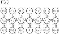
- FIG. 3 The most suitable tool for implementing artificial intelligence is Figure 3 shown second neural network, preferably a recurrent neural network.
- the following architectures and networks can be used to implement artificial intelligence: recurrent neural networks, fixed point convergence networks, Elman-Jordan networks, ECNN, causal-retro-causal networks, LSTM, gated recurrent units.
- Neural networks make it possible to provide a statement on the forecast reliability of the switching states or switching times, as well as to distinguish safe from unsafe states. Possibilities for this are: deriving the uncertainty from a model error, scattering of the output of models, deriving a bandwidth of a conditional density estimation, generating model output by creating scenarios.
- the second neural network shown should be able to learn statistical and system-immanent dynamic relationships between input variables and output variables.
- the second neural network can learn an increased traffic volume at a certain time and, taking these statistical relationships into account, predict a higher red probability for a given signal group at that time.
- a switching point is the point in time at which a signal group makes a signal change.
- the signal group can switch from the signal "clear to proceed", which is indicated by a green signal, to "blocked to proceed", which is indicated by a red signal, for example.
- This can be formalized as a regression problem between a real switching point and a predicted switching point.
- the architecture of the forecast model may be able to reflect a certain memory effect.
- the artificial intelligence can provide a forecast matrix that contains a forecast probability for a signal state for each point in time in a given time window and for each signal group of a signal system.
- the forecast matrix can contain a probability for a green signal of a signal group or a probability for a red signal of a signal group for each time window.
- This task can be solved using a multi-objective learning problem.
- a forecast of signal states, in particular probabilities for signal states and remaining time forecasts until the switching point from one signal state to a subsequent signal state for all signal groups of a signal system can be solved using a neural network that solves the learning problem dynamically and in an integrated manner.
- the artificial intelligence does not require any information about a precise circuit diagram of the traffic signal system or any expert knowledge about the causal relationships in traffic control. It is highly scalable with regard to application to different traffic signals, since the artificial intelligence only needs to be calibrated or trained using a given data set.
- the forecast model can be used in real time and can be retrained on current data at any time.
- An additional advantage is the ability to generalize, which allows the system to be transferred to intersections of any complexity without expert knowledge.
- Neural networks are parametric functions that can be trained using data-driven stochastic gradient descent methods. This enables neural networks to recognize non-linear relationships without expert knowledge.
- One of the technical features of neural networks is that the architecture used provides an integrated forecast of switching time and state. Recurrent neural networks enable a higher forecast quality because they are able to better represent the underlying dynamics of the system being modeled and any memory effects that occur than pure input-output models, such as feed-forward networks.
- Figure 1 shows a schematic representation of the structure of a signal system 14 with three signal groups 6, 7, 8.
- the signal system 14 has a control unit 5 which is connected to detectors 1, 2, 3.
- the detectors 1, 2, 3 record various parameters of traffic on at least one road on which the signal system 14 with the signal groups 6, 7, 8 is arranged. With the help of the detectors 1, 2, 3, vehicles are detected on the road, for example. This allows the signal system 14 to be controlled in a way that is adapted to the traffic, depending on the vehicle density on the road(s).
- a computing unit 4 is provided which receives information about the traffic on the road either directly from the detectors 1, 2, 3 or via the control unit 5. In this way, the computing unit 4 also receives information about the traffic, in particular about the traffic density on the road(s) at an intersection.
- the data of the detectors 1, 2, 3 are received, for example, by the computing unit 4 via a first input 9.
- the control unit 5 has a data memory and control programs with which, depending on various parameters and in particular depending on traffic data recorded by the detectors 1, 2, 3, the signal groups 6, 7, 8 of the signal system 14 are controlled in such a way that a desired traffic flow can take place on the road, in particular across an intersection.
- the signal groups 6, 7, 8 are designed as light signal groups in the embodiment shown. Each signal group has an indicator for red light, an indicator for yellow light and an indicator for green light. The The meaning of the individual light colours for traffic is regulated on a country-specific basis.
- the signal groups 6, 7, 8 can also have other signals to enable or disable a journey.
- the control unit 5 also passes the control signals for the signal groups of the signal system to a second input 10 of the computing unit 4.
- the computing unit 4 therefore also has the information about which signal group is currently displaying which signal.
- a fourth input 15 is provided, via which the control unit 5 transmits to the computing unit 4 further information about the control program that the control unit 5 uses to control the signal system 14 with the signal groups 6, 7, 8.
- the information about the control program can include, for example, the cycle time, information about whether it is a central control, a local control, or a control that can be activated by traffic, whether there are errors in the control or the traffic light system, whether it is a traffic-dependent control, whether there is an error in the detector, whether it is a higher-level control or a central control, the state of the control unit, etc.
- the computing unit 4 also has a third input 11, via which further information is received.
- the further information can include, for example, traffic information, information about a public means of transport, a report of a public means of transport at a reporting point or a request for free travel by a public means of transport, etc.
- the report of the means of transport can, for example, contain information about the type of transport or an identifier of the means of transport, such as a line number of the means of transport.
- a means of public transport can be a bus, a tram, etc.
- the computing unit 4 has a time unit with which the current time can be determined.
- the computing unit 4 also has information about what time, day of the week, month, calendar day, year, etc. it is currently.
- information about a current holiday can also be available to the computing unit 4 or made available via the third input 11.
- Traffic reports can be, for example, information about accidents, traffic jams, heavy traffic, road closures, etc.
- the computing unit 4 also has the previously explained artificial intelligence in the form of a computer program and/or in the form of hardware circuits.
- the artificial intelligence which is fed with the real status information, predicts at least one switching point in the signal group in the fixed time cycle.
- the first neural network calculates estimated state information as a replacement for real state information or components of the real state information which are not received in time or are received incorrectly for a current point in time in the fixed time cycle.
- the first neural network outputs the estimated state information for the current point in time in the fixed time cycle to the artificial intelligence, whereby the estimated state information replaces the real state information or the components of the real state information which were not received in time or are received incorrectly.
- the artificial intelligence is, for example, a second neural network as described in Figure 3 is shown.
- the computing unit 4 can contain both the first neural network and the artificial intelligence. Instead of the computing unit 4, however, two computing units can also be provided, which are arranged adjacent to each other. In this variant, one of the two computing units executes the first neural network and the other computing unit executes the artificial intelligence.
- the computing unit on which the artificial intelligence is executed is, for example, dedicated hardware.
- the control unit 5 is, for example, a Sitraffic sX traffic control unit or a control unit from the Sitraffic C900 family.
- the first neural network enables the artificial intelligence to create a meaningful forecast of the expected switching times of signal groups 6, 7, 8 at a fixed time interval (for example once per second) and to make it available to the vehicles 13 in the surrounding area. This is the case even if the communication path between the computing unit 4 and the control unit 5 is disrupted during operation for various reasons.
- the first neural network creates a mechanism that enables a more robust forecast at a fixed time interval despite missing or significantly delayed data.
- the artificial intelligence is designed to predict a switching time of at least one signal group from one signal state to a following signal state based on at least one of the available parameters.
- the remaining time duration of the current signal state and also switching times between future signal states of the signal group can thus be predicted for at least one signal group.
- the time horizon up to which the signal curve and thus the switching times between the signal states of a signal group are predicted can be in the range of a few seconds up to 30 seconds and even longer than 30 seconds.
- the forecast can determine a probability for the predicted remaining time duration of the current signal state of a signal group.
- a probability for the predicted time duration and the predicted switching times between the signal states can also be determined for future signal states.
- the determination of the switching times between signal states of a signal group can be updated at specified time intervals. For example, the switching times between the signal states of the signal group can be updated every second for the specified future time horizon of, for example, greater than 30 seconds, in particular greater than 120 seconds. can be predicted. In addition, the probabilities for the signal states of the signal group can also be determined every second. This simultaneously determines a remaining duration of the current signal state of the signal group.
- the computing unit 4 can be designed to determine the switching times for a transition between signal states of the signal systems for a predetermined future time horizon for several signal groups of the signal system, in particular for all signal groups of the signal system. In addition, the computing unit 4 can be designed to determine the probabilities for the remaining durations of the current signal states of the signal groups of the signal system for several signal groups 6, 7, 8, in particular for all signal groups of the signal system.
- the switching times and the probabilities for the following signal states of the signal groups can also be determined for the change of further signal states of the signal groups of the signal system.
- the computing unit 4 can be designed to determine the switching times of the signal groups of the signal systems and the probabilities for the signal states of the signal groups of the signal system for several signal systems.
- the computing unit 4 and the control unit 5 can also be designed in a single computing unit. The probabilities are determined by the computing unit 4 from a learned historical comparison of the predicted switching times with the actually measured switching times. Switching times for certain traffic situations and states of the signal system are predicted for a specified future period.
- At least one future switching time or a remaining time of the current signal state or a duration of a future signal state is transmitted from the computing unit 4 to a vehicle 13 via an output 12, for example wirelessly.
- the switching times of future transitions between signal states for a predetermined future time horizon of at least one of the signal groups of the signal system, in particular all signal groups of the signal system can be transmitted to the vehicle 13.
- the durations of the current signal states of the signal groups and the durations of the future signal states of the signal groups for a predetermined future time horizon can be transmitted to the vehicle 13 for at least one of the signal groups of the signal system, in particular for all signal groups of the signal system. Furthermore, this information can also be transmitted to an external computing unit 16.
- the vehicle 13 and/or the external computing unit 16 can use the transmitted information about the future switching times of the signal groups of the signal system and/or the durations of the current and/or future signal states of the signal groups and/or the probabilities of the current and/or future signal states of the signal groups for a statistical evaluation, a travel route planning and/or a control of a speed of the vehicle or an output of information to a driver.
- the data in the vehicle 13 can be used by a control unit to automatically control a speed of the vehicle.
- the information in the vehicle 13 into a navigation system or navigation program and taken into account for route planning.
- the information can also be shown to the driver via a display, for example a display of a mobile phone or a display of an integrated navigation system.
- the external computing unit 16 can also be designed to wirelessly transmit the transmitted information about the future switching times of the signal groups of the signal system and their probabilities to vehicles 13.
- the external computing unit 16 can be implemented as a cloud or as a single external computing unit. Depending on the selected embodiment, the real status information recorded by the computing unit 4 can also be transmitted to the external computing unit 16.
- the real status information is sent to a cloud as a computing unit 16, for example.
- the first neural network and the artificial intelligence can also be implemented in the cloud, since simply sending the real status information causes less data traffic on an LTE route than if the forecast values are transmitted at the same time. Packets can also potentially be lost on this route or reach the cloud with a significant delay. The reasons for this are, for example, firstly, an overload of the mobile network or, secondly, a failure of hardware components between the local transmitting unit and the first neural network in the cloud.
- the first neural network in the cloud can also advantageously compensate for these transmission losses.
- the predictions of the artificial intelligence can be made available and used not only locally at the signal system 14, but also centrally. for example by navigation system providers, automotive OEMs and city administrators.
- the external computing unit 16 can be designed to train the first neural network and/or the artificial intelligence and to implement the corresponding models for predicting the state information or the switching times and the probability of the signal states.
- the trained first neural network and/or the trained artificial intelligence can then be transmitted to the computing unit 4 as a computer program.
- the interface between the external computing unit 16 and the computing unit 4 can be wireless or wired.
- the external computing unit 16 can also calculate the forecast for the switching times and/or calculate the probabilities of the signal states.
- the external computing unit 16 can thus transmit the determined probabilities of the current and future signal states of the signal groups and the determined future switching times of the signal groups to the computing unit 4.
- the external computing unit 16 can be designed to transmit the information about the switching times and the probabilities of the switching times to further computing units or to the vehicles 13.
- the computing unit 4 can transmit the switching times of the signal groups and/or the probabilities of the signal states to the vehicles 13, for example wirelessly.
- the computing unit 4 and/or the external computing unit 16 can train the first neural network and/or the artificial intelligence.
- the data that the computing unit 4 needs to predict the switching times and/or the probabilities of the signal states can be requested from the control unit 5 via a data connection.
- the parameters can be queried and received every second by the control unit 5.
- the data required to train the model can be transmitted every second from the computing unit 4 and/or from the control unit 5 to the external computing unit 16.
- only the computing unit 4 can carry out the training of the first neural network and/or the artificial intelligence.
- the first neural network and/or the artificial intelligence can be transmitted externally to the computing unit 4.
- the functions of the first neural network and the artificial intelligence can also be combined in a third neural network, which replaces the first neural network and the artificial intelligence.
- the previous statements on Figure 1 apply accordingly.
- Figure 2 shows a schematic representation of an intersection 17 at which a second road 18 joins a first road 19 or branches off from it.
- first road 19 On the first road 19, to the left of the intersection 17, the first signal group 6 and the first detector 1 are arranged.
- the detectors 1, 2, 3 are connected to the control unit 5 and the computing unit 4.
- the computing unit 4 and the control unit 5 can also be integrated in a single computing unit, depending on the selected embodiment.
- the computing unit 4 and/or the control unit 5 are arranged in a switch box at the side of the road.
- the signal groups 6, 7, 8 of the signal system 14 are connected to the control unit 5.
- the detectors 1, 2, 3 are designed to detect vehicles approaching the intersection 17.
- the control unit 5 can thus carry out a traffic-dependent control of the signal states of the signal groups 6, 7, 8 of the signal system 14 depending on the current traffic volume.
- the control unit 5 can be connected to the computing unit 4 via an Ethernet, for example. This connection can be used to transmit current real status information about the signal program, the circulation time, the cycle time for controlling the signal states of the signal groups, the data from the detectors, information about messages from public transport, etc. at a fixed time interval, for example every second.
- the computing unit 4 executes, for example, the first neural network and the artificial intelligence.
- these two functions are provided by separate, modular computing units that replace the computing unit 4.
- one or both functions are provided alternatively or additionally in a cloud.
- the artificial intelligence is implemented, for example, as a second neural network, for example as a recurrent neural network, fixed point convergence network, Elman-Jordan network, ECNN, causal-retro-causal network, LSTM or gated recurrent network.
- a second neural network for example as a recurrent neural network, fixed point convergence network, Elman-Jordan network, ECNN, causal-retro-causal network, LSTM or gated recurrent network.
- the functions of the first neural network and the artificial intelligence can also be combined in a third neural network, which replaces the first neural network and the artificial intelligence.
- the previous statements on Figure 2 apply accordingly.
- Figure 3 shows a second neural network in the form of a recurrent neural network as a simple, schematic example of an implementation of artificial intelligence.
- a state transition is determined by a previous internal hidden state of the system s t-1 at time t-1 and the influence of an external parameter u t at time t on the new state s t at time t.
- the states s t , s t-1 etc. can be parameters or vectors with several parameters.
- the output equation determines the determinable output vector y t .
- the external parameters u t are the parameters that are detected with the detectors.
- the output vector y t are the signal states of the signal groups of the signaling system.
- an input vector u at time t will act on the hidden layer with the states s t with weights of a two-dimensional matrix B.
- the hidden layer will transition to the output vector y t with weights of a two-dimensional matrix C.
- the state s t-1 will act on the hidden layer with weights of a two-dimensional matrix A.
- the hidden layer will act on the state s t with a unit matrix id.
- the output function NN(s t ; w) is implemented as a linear function.
- the second neural network has a hidden layer with the hidden states s t , where t defines an incremental point in time.
- an input vector u t with the weights of matrix B will act on the respective hidden state.
- an output vector y t is determined from the hidden state s t with the weights of matrix C.
- a hidden state s t-1 acts on the following state s t with the weights of matrix A.
- One task is to determine the model of the output vector y t as precisely as possible.
- the influence of three previous states, i.e. s t-3 , s t-2 and s t-1 together with the current hidden state s t is used to determine future hidden states s t+1 , s t+2 etc. and also future output vectors y t+1 , y t+2 etc.
- the second neural network is trained in such a way that the matrices A, B and C are determined so that the output vectors y t calculated with the second neural network correspond as closely as possible to the measured output vectors y t .
- the parameters that are fed to the computing unit 4 via the first input 9, the third input 11 and the fourth input 15 are used as input vectors u t to train the second neural network.
- only some of the parameters can be used as input vectors.
- At least one switching point of a signal group from a current signal state to a subsequent signal state is determined as the output vector.
- the output vector can include a probability for the correctness of a predicted signal state of at least one signal group of the signaling system.
- the output vector can be determined for a predetermined Point in time can have the switching points in time between the occurring signal states of a signal group.
- the output vector can have probabilities for the signal states of at least one signal group for a predetermined forecast period.
- the output vector can have the switching points in time and/or the probabilities for the signal states of several signal groups of the signal system, in particular for all signal groups of the signal system. The measured output vectors are compared with the calculated output vectors.
- the calculated output vectors are adapted to the measured output vectors. If the difference between the calculated output vector and the measured output vector for each parameter is less than, for example, 5%, the learning process is terminated and the model or the second neural network with the matrices A, B, C is retained.
- This model is used by the computing unit 4 for a future prediction of switching points in time and/or probabilities of the signal states.
- a recurrent neural network with error correction can be used as the second neural network.
- Figure 4 shows a schematic representation of a first neural network with the structure of a closed, historically consistent neural network, where the functionality of the network is shown for chronologically successive calculation steps.
- a timeline for the time t is shown schematically, with the time t leading to the right into the future.
- Times t-3, t-2, t-1, t are shown for calculation steps of the neural network.
- the time course starts with the time t-3 and continues through the times t-2, t-1, to the current time t.
- the first neural network is implemented in the form of hardware and/or software in a computer.
- the computer is any computing unit, for example a field device.
- the chosen representation is only schematic with respect to the number of calculation times t, since the times at which calculations are carried out can, in real cases, extend from a time of t-432, t - 288 or t - 120 to the current time t, for example.
- the first neural network uses an internal state vector s t which, in addition to non-observables, i.e. hidden variables, has a fixed number of observables, i.e. measurable quantities.
- the values of the observables and the non-observables of the internal state vector are assigned starting values which form a bias vector s 0.
- the starting values of the bias vector s 0 can be determined as part of the training of the first neural network.
- the internal state vector s t-3 is formed from the bias vector s 0 at time t - 3, which has the starting values for the observables and the non-observables and is stored in a storage unit 26.
- the index t-3 indicates the time for the calculation step.
- real state information which influences the switching times of a signal group of a signaling system, is transmitted via a first data input 21 in the form of an external state vector y t ⁇ 3 d with several external state values.
- the external state values represent, for example, current signal group states, system states, detector values and public transport telegrams.
- the external state values are fed to a first processing unit 22 with a negative sign.
- a top first specified number n of observables of the internal state vector s t-3 is also fed to the first processing unit 22.
- the first specified number n corresponds to the number of external state values of the external state vector y t ⁇ 3 d .
- the first processing unit 22 determines the difference between the real state information of the external state vector y t ⁇ 3 d and the values of the observables of the internal state vector s t-3 , which correspond to and estimate the external state values. For each external state value, the internal state vector has an observable.
- the differences between each (measured or real) external state value of the external state vector y t ⁇ 3 d and the value of the corresponding observables of the internal state vector s t-3 at time t - 3 are fed as a first error vector with negative characteristics to a third processing unit 23. Further processing steps can take place here, which are explained further below; the first error vector is then initially further processed before being fed to the third processing unit 23.
- the internal state vector s t -3 is also transmitted to the third processing unit 23.
- the third processing unit 23 uses an activation function, which in this example is designed as a hyperbolic tangent function (tan h ), and performs the following calculation: tanh s t ⁇ 3 + ⁇ ID 0 ⁇ ID 0 s t ⁇ 3 ⁇ y t ⁇ 3 d ⁇ ID 0 denotes a diagonal negative identity matrix whose dimension is equal to the dimension of the number of components of the respective vector with which the matrix is multiplied. The first n diagonal elements of the matrix have the value -1. All other values of the matrix have the value 0.
- an activation function which in this example is designed as a hyperbolic tangent function (tan h ), and performs the following calculation: tanh s t ⁇ 3 + ⁇ ID 0 ⁇ ID 0 s t ⁇ 3 ⁇ y t ⁇ 3 d ⁇ ID 0 denotes a diagonal negative identity matrix whose dimension is equal to the dimension of the number of components of the respective vector with
- [ Id, 0] denotes a diagonal positive identity matrix whose dimension is equal to the dimension of the number of components of the respective vector with which the matrix is multiplied.
- the first n diagonal elements of the matrix have the value +1. All other values of the matrix have the value 0.
- the third processing unit 23 can also use another activation function, in particular a sigmoid function, instead of the function tan h .
- Matrix A is a two-dimensional matrix that has weighting factors as elements. It is created during the training of the first neural network with optimized weighting factors.
- the external state vector y t ⁇ 3 d has at least one external state value, in particular several external state values, for example from different detectors and control units.
- the subscript t-3 indicates the point in time for which the external state values were determined.
- s t -3 (signal group states, system states, detector values, public transport telegrams, first non-observable, second non-observable, ..., m-th non-observable)
- the internal state vector s t -3 has the external state values predicted by the neural network at a first fixed number of n positions.
- the first processing unit 22 uses the first n observables of the internal state vector s t -3 , the number of which is equal to the number of external state values of the external state vector y t ⁇ 3 d and determines a difference between the observable and the external state value for each position. This creates an error vector for the state values, which can be described as follows: ID 0 s t ⁇ 3 ⁇ y t ⁇ 3 d
- the output of the first processing unit 22 is connected to a fourth processing unit 27.
- the first processing unit 22 carries out a vector subtraction, whereby the first n observables of the internal state vector s t -3 are subtracted from the negative values of the n components of the external state vector y t ⁇ 3 d are added. The result is passed on to the fourth processing unit 27.
- a masking vector is applied via an input 28 mask t ⁇ 3 y which contains information about which of the (measured) external state values of the external state vector y t ⁇ 3 d are correct and which external state values are incorrect or missing.
- the masking vector mask mask t ⁇ 3 y can be created, for example, by a local or external computing unit that monitors the incoming signals with the real state information and checks and verifies the external state values contained therein using defined procedures.
- the masking vector mask t ⁇ 3 y contains the value 1 for the external state values that were measured, and for the external state values that were not measured or that were faulty are, the value 0 at the corresponding position of the masking vector mask t ⁇ 3 y .
- the fourth processing unit 27 carries out a vector multiplication with the error vector output by the first processing unit 22 and the masking vector. Consequently, during this vector multiplication in the fourth processing unit 27, the corresponding correction values supplied by the first processing unit 22 are set to the value 0 and are therefore not used for further calculation, i.e. are hidden. If correct sensor data is present, the value 1 is stored at the corresponding points of the masking vector. Consequently, during the vector multiplication in the fourth processing unit 27, the corresponding correction values supplied by the first processing unit 22 are multiplied by the value 1 and are therefore used for further calculation and forwarded to the third processing unit 23.
- the result of the vector multiplication is passed on to the third processing unit 23 as an error vector with a negative sign.
- Figure 5 shows the case where no error vector is determined for the current time t taking into account an external state vector, because the external state values for the current time t are not received in time. Instead, an estimated state vector y t is output, which estimates the external state values.
- the first n observables of the internal state vector s t are output as estimated state values, which form the estimated state vector y t .
- the first neural network is trained using known training methods such as backpropagation, whereby the state values or the estimated state vector y t estimated by the first neural network for the current time t are compared with the (actually occurring and measured) external state values or the external state vector y d t .
- the weighting factors of the matrix A are optimized until the first neural network determines the state values or state vectors as accurately as possible according to the measured external state values for the current time t.
- up to 288 or up to 432 calculation steps from the past can be calculated using the first neural network.
- the calculation steps can, for example, be carried out for points in time in a fixed time cycle, each of which has a time interval of one second.
- Figure 4 shown first neural network to the one in Figure 3 shown second neural network.
- the internal state vector s t for the current time t is taken from the memory unit 26, multiplied by the diagonal positive identity matrix [Id,0] and then used as an external parameter vector u t to Figure 3 shown second neural network. Any backward gradient flow from the second neural network into the first neural network is prevented.
- the matrix A of the first neural network in Figure 4 and the matrix A of the second neural network in Figure 3 are different matrices.
- the second neural network can also have a different architecture than in Figure 3 shown. Different network architectures that can be considered have already been mentioned previously; for example, the second neural network could also be a feed-forward network.
- the combination of the first neural network with the second neural network can also be understood as an extension of the previous embodiments.
- the combination of the first neural network with the second neural network can also be viewed as a higher-level third neural network with a heterogeneous architecture.
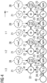
- Figure 6 shows another embodiment of a third neural network, which combines the functions of the first neural network Figure 4 or Figure 5 and the second neural network Figure 3 and thus replaces them.
- the third neural network also determines for future points in time t + 1, t + 2, ... both a state vector s t +1 , s t +2 , ... and estimated state vectors y t+1 , y t+2 , ....
- the chosen representation is in relation to the number of Calculation times t are only shown schematically, since the times at which calculations are carried out can, in real cases, extend, for example, from a time of t- 288 to a time of t + 144.
- the calculations of the third processing unit 23 are also carried out for future times t + 1, t + 2, ... However, for the future times t + 1, t + 2, ... no more error vectors are calculated taking into account external state vectors y t d determined because these real measurements are not yet available.
- estimated state vectors y t+1 , y t+1 , ... are output for the future times t + 1, t + 2 , ..., which estimate the external state values at these times.
- the first n observables of the internal state vector s t are output as estimated state values, which form the estimated state vector y t+1 .
- the first n observables of the internal state vectors s t +2 , s t +2 ,... are output as estimated state values, which form the estimated state vectors y t+2 , y t+3 , ...
- the information required to predict the switching times of the signal groups of the signal system is therefore available as signal group states for the future times t + 1, t + 2, ... directly in the estimated state vectors y t+1 , y t+ 1 , ...
- the signal group states are calculated as part of the estimated state vectors y t+1 , y t+1 , ... at second intervals up to a time t + 120.
- the third neural network therefore predicts the signal group states of the signal system for the next 120 seconds.
- the switching times are therefore also available implicitly, since these arise directly from any change in the predicted signal group states.
- the predicted switching times can be taken directly from other components of the estimated state vector y t , for example the system states.
- the third neural network is trained using well-known training methods such as backpropagation, as already for the Figure 4 and Figure 5
- the first neural network shown was explained.
- up to 288 calculation steps in the past and up to 144 calculation steps in the future can be calculated using the third neural network.
- the calculation steps can, for example, be carried out for points in time that are one hour apart.
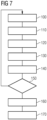
- Figure 7 shows a schematic representation of a program flow for a method for predicting switching times of a signal group of a signaling system.
- a first program step 100 real status information in the form of external status values is recorded over a predetermined period of time using sensors, among other things.
- the external status values can contain, for example, signal group states, system states, detector values and public transport telegrams. They are fed to inputs of the first neural network described above.
- the first neural network estimates state information for a current point in time.
- a third program step 120 it is checked whether the real status information for the current point in time was received in time, completely and without errors.
- the sensors provide information about which of the transmitted external status values are missing or are defective.
- a computing unit can, for example, use plausibility checks to check whether the external status values provided by the sensors are defective. If the values from the sensors are missing, the computing unit detects that the sensor data is missing.
- the real status information is represented by an external status vector. Now all components of the external status vector, i.e. each external status value, are individually checked to see whether it arrived on time and without errors for the current point in time in a fixed time cycle. This information is required for the following program step.
- the real state information and/or the estimated state information for the current point in time are transmitted to the second neural network described above.
- the estimated state information replaces the real state information as a whole or its components if they were not received on time or were received incorrectly. For example, the components of the external state vector that did not arrive on time and without errors for the current point in time in the fixed time cycle are replaced by the corresponding components of the estimated state information.
- a computing unit uses a software and/or hardware structure to execute the previously described second neural network and predict the switching times.
- the program then branches to a sixth program step 150, where it is checked whether a specified minimum number of calculations have been carried out in the past with the first neural network and the second neural network. If this is not the case, the program branches back to the first program step 100 and further measurements and calculations are carried out.
- the number of calculations into the past can be fixed over a period of several minutes or hours.
- calculations can typically be performed every second.
- the program branches to a seventh program step 160.
- the prediction of the second neural network is output.
- the prediction of the switching times is transmitted to vehicles in the area, for example, in an eighth program step 170.
- the vehicles can then use this information, for example, to issue adapted driver assistance recommendations regarding driving speed to a driver or to adapt route planning accordingly.
- the predictions can also be used directly, which eliminates the query in the sixth program step 150.
- the query in the sixth program step 150 can relate only to the first neural network, only to the second neural network, or to both neural networks.
- the previous statements on the first neural network and the second neural network apply similarly to the third neural network, which combines the functions of the first neural network and the second neural network.
- the basic idea here is that the third neural network is initially fed with real state information for a period of, for example, 120 seconds before starting to use the predictions of the third neural network.
Landscapes
- Physics & Mathematics (AREA)
- Engineering & Computer Science (AREA)
- General Physics & Mathematics (AREA)
- Theoretical Computer Science (AREA)
- Life Sciences & Earth Sciences (AREA)
- General Health & Medical Sciences (AREA)
- Artificial Intelligence (AREA)
- Computational Linguistics (AREA)
- Data Mining & Analysis (AREA)
- Evolutionary Computation (AREA)
- Biomedical Technology (AREA)
- Molecular Biology (AREA)
- Computing Systems (AREA)
- General Engineering & Computer Science (AREA)
- Biophysics (AREA)
- Mathematical Physics (AREA)
- Software Systems (AREA)
- Health & Medical Sciences (AREA)
- Chemical & Material Sciences (AREA)
- Analytical Chemistry (AREA)
- Atmospheric Sciences (AREA)
- Traffic Control Systems (AREA)
Claims (13)
- Procédé de prédiction d'instants de commutation d'un groupe de signaux d'un équipement de signalisation en vue de commander un flux de trafic, avec lequeldes informations d'état réelles (..., y<d>t-3, y<d>t-2, y<d>t-i, y<d>t), qui influencent les instants de commutation du groupe de signaux, sont reçues dans un rythme de temps fixe, etune unité de calcul prédit au moins un instant de commutation du groupe de signaux dans le rythme de temps fixe à l'aide d'une intelligence artificielle à laquelle sont acheminées les informations d'état réelles (..., y<d>t-3, y<d>t-2, y<d>t-i, y<d>t),caractérisé en ce queles informations d'état réelles (..., y<d>t-3, y<d>t-2, y<d>t-i, y<d>t) sont acheminées en tant que signaux d'entrée à un premier réseau neuronal,le premier réseau neuronal calcule des informations d'état estimées (yt) en tant que remplacement des informations d'état réelles (y<d>t) ou d'éléments constitutifs des informations d'état réelles (y<d>t) qui ne sont pas reçus en temps voulu ou sont reçus de manière erronée pour un instant actuel (t) dans le rythme de temps fixe, etle premier réseau neuronal délivre les informations d'état estimées (yt) pour l'instant actuel (t) dans le rythme de temps fixe à l'intelligence artificielle, les informations d'état estimées (yt) remplaçant les informations d'état réelles (y<d>t) ou les éléments constitutifs des informations d'état réelles (y<d>t) qui n'ont pas été reçus en temps voulu ou reçus de manière erronée,ou caractérisé en ce quel'intelligence artificielle est un troisième réseau neuronal auquel les informations d'état réelles (..., y<d>t-3, y<d>t-2, y<d>t-i, y<d>t) sont acheminées en tant que signaux d'entrée,le troisième réseau neuronal calcule des informations d'état estimées (yt) en tant que remplacement des informations d'état réelles (y<d>t) ou d'éléments constitutifs des informations d'état réelles (y<d>t) qui ne sont pas reçus en temps voulu ou sont reçus de manière erronée pour un instant actuel (t) dans le rythme de temps fixe, etle troisième réseau neuronal utilise les informations d'état estimées (yt) pour l'instant actuel (t) dans le rythme de temps fixe en vue de prédire l'au moins un instant de commutation du groupe de signaux, les informations d'état estimées (yt) remplaçant les informations d'état réelles (y<d>t) ou les éléments constitutifs des informations d'état réelles (y<d>t) qui n'ont pas été reçus en temps voulu ou reçus de manière erronée,des informations d'état pour un instant actuel étant estimées par le premier réseau neuronal ou le troisième réseau neuronal, un contrôle étant ensuite effectué afin de vérifier si les informations d'état actuelle pour l'instant actuel ont été reçues en temps voulu, entièrement et sans erreur, et les informations d'état réelles (..., y<d>t-3, y<d>t-2, y<d>t-i, y<d>t) étant ensuite remplacées par les informations d'état estimées dans le cas où les informations d'état réelles n'ont pas été reçus en temps voulu ou reçus de manière erronée.
- Procédé selon la revendication 1, avec lequel les informations d'état réelles (..., y<d>t-3, y<d>t-2, y<d>t-i, y<d>t) contiennent :des états de groupes de signaux, notamment de l'équipement de signalisation et/ou de plusieurs ou de tous les équipements de signalisation dans une région,des états de système, notamment d'une unité de commande de l'équipement de signalisation et/ou d'unités de commande de plusieurs ou de tous les équipements de signalisation dans une région,des valeurs de détecteur, notamment de l'équipement de signalisation et/ou de plusieurs ou de tous les équipements de signalisation dans une région, et/ou des messages de véhicules, notamment des notifications et/ou des demandes de moyens de transport public, notamment des télégrammes de transport en commun.
- Procédé selon l'une des revendications précédentes, avec lequel le premier réseau neuronal ou le troisième réseau neuronal est un réseau neuronal historiquement cohérent, lequel calcule continuellement les informations d'état réelles (y<d>t) pour l'instant actuel (t) dans le rythme de temps fixe.
- Procédé selon la revendication 3, avec lequel, dans le cas où les informations d'état réelles (y<d>t) pour l'instant actuel (t) sont reçues en temps voulu dans le rythme de temps fixe, le premier réseau neuronal détermine un écart entre les informations d'état réelles (y<d>t) et les informations d'état estimées (yt) pour l'instant actuel (t) et les utilise pour la correction d'erreur, et les informations d'état réelles (y<d>t) pour l'instant actuel (t) sont acheminées à l'intelligence artificielle dans le rythme de temps fixe.
- Procédé selon la revendication 3 ou 4,avec lequel les informations d'état réelles passées (..., y<d>t-3, y<d>t-2, y<d>t-i) pour un instant passé (..., t-3, t-2, t-1) sont reçues retardées ultérieurement, etavec lequel le premier réseau neuronal ou le troisième réseau neuronal détermine un écart entre les informations d'état réelles passées (..., y<d>t-3, y<d>t-2, y<d>t-i) et les informations d'état estimées passées (..., yt-3, yt-2, yt-i) et les utilise pour la correction d'erreur.
- Procédé selon l'une des revendications précédentes, avec lequel le premier réseau neuronal et/ou l'intelligence artificielle ou le troisième réseau neuronal sont exécutés dans une unité de calcul externe, notamment dans un nuage.
- Procédé selon l'une des revendications précédentes, avec lequel le premier réseau neuronal ou le troisième réseau neuronal sont préalablement entraînés avec des informations d'état réelles (..., y<d>t-3, y<d>t-2, y<d>t-i, y<d>t) de telle sorte qu'il apprend l'estimation des informations d'état (yt) pour l'instant actuel (t).
- Procédé selon la revendication 7, avec lequel au moins une partie de l'entraînement du premier réseau neuronal ou du troisième réseau neuronal est effectuée dans une unité de calcul externe, notamment dans un nuage, et avec lequel, après l'achèvement de l'entraînement, le premier réseau neuronal entraîné ou le troisième réseau neuronal entraîné est transmis à une unité de calcul de l'équipement de signalisation.
- Procédé selon la revendication 7, avec lequel le premier réseau neuronal ou le troisième réseau neuronal est entraîné pendant le fonctionnement de l'équipement de signalisation et la prédiction des instants de commutation dans des intervalles de temps prédéfinis et le premier réseau neuronal nouvellement entraîné ou le troisième réseau neuronal nouvellement entraîné et ensuite utilisé.
- Procédé selon l'une des revendications précédentes, avec lequel le premier réseau neuronal ou le troisième réseau neuronal traitent au moins une information d'état avec des non observables supplémentaires dans un vecteur d'état interne.
- Support de données lisible par ordinateur, sur lequel est enregistré un programme informatique, lequel met en oeuvre le procédé selon l'une des revendications 1 à 10 lorsqu'il est exécuté par un processeur.
- Programme informatique, lequel est exécuté dans un processeur et met alors en oeuvre le procédé selon l'une des revendications 1 à 10.
- Arrangement de prédiction d'instants de commutation d'un groupe de signaux d'un équipement de signalisation en vue de commander un flux de trafic,comprenant une interface, conçue pour recevoir des informations d'état réelles (..., y<d>t-3, y<d>t-2, y<d>t-i, y<d>t), qui influencent les instants de commutation du groupe de signaux, dans un rythme de temps fixe,comprenant une unité de calcul, conçue pour prédire au moins un instant de commutation du groupe de signaux dans le rythme de temps fixe à l'aide d'une intelligence artificielle à laquelle sont acheminées les informations d'état réelles (..., y<d>t-3, y<d>t-2, y<d>t-i, y<d>t),caractérisé parun premier réseau neuronal auquel les informations d'état réelles (..., y<d>t-3, y<d>t-2, y<d>t-i, y<d>t) sont acheminées en tant que signaux d'entrée,le premier réseau neuronal étant conçu pour calculer des informations d'état estimées (yt) en tant que remplacement des informations d'état réelles (y<d>t) ou d'éléments constitutifs des informations d'état réelles (y<d>t) qui ne sont pas reçus en temps voulu ou sont reçus de manière erronée pour un instant actuel (t) dans le rythme de temps fixe,et l'arrangement étant conçu pour délivrer les informations d'état estimées (yt) pour l'instant actuel (t) dans le rythme de temps fixe à l'intelligence artificielle, les informations d'état estimées (yt) remplaçant les informations d'état réelles (y<d>t) ou les éléments constitutifs des informations d'état réelles (y<d>t) qui n'ont pas été reçus en temps voulu ou reçus de manière erronée,ou caractérisé parun troisième réseau neuronal, lequel met en oeuvre l'intelligence artificielle est et auquel les informations d'état réelles (..., y<d>t-3, y<d>t-2, y<d>t-i, y<d>t) sont acheminées en tant que signaux d'entrée,le troisième réseau neuronal étant conçu pour calculer les informations d'état estimées (yt) en tant que remplacement des informations d'état réelles (y<d>t) ou d'éléments constitutifs des informations d'état réelles (y<d>t) qui ne sont pas reçus en temps voulu ou sont reçus de manière erronée pour un instant actuel (t) dans le rythme de temps fixe, etle troisième réseau neuronal étant conçu pour utiliser les informations d'état estimées (yt) pour l'instant actuel (t) dans le rythme de temps fixe en vue de prédire l'au moins un instant de commutation du groupe de signaux, les informations d'état estimées (yt) remplaçant les informations d'état réelles (y<d>t) ou les éléments constitutifs des informations d'état réelles (y<d>t) qui n'ont pas été reçus en temps voulu ou reçus de manière erronée,le premier réseau neuronal ou le troisième réseau neuronal étant conçu pour estimer des informations d'état pour un instant actuel, l'arrangement étant conçu pour vérifier ensuite si les informations d'état actuelle pour l'instant actuel ont été reçues en temps voulu, entièrement et sans erreur, et l'arrangement étant conçu pour remplacer ensuite les informations d'état réelles (..., y<d>t-3, y<d>t-2, y<d>t-i, y<d>t) par les informations d'état estimées dans le cas où les informations d'état réelles n'ont pas été reçues en temps voulu ou reçues de manière erronée.
Applications Claiming Priority (2)
| Application Number | Priority Date | Filing Date | Title |
|---|---|---|---|
| DE102019218903.2A DE102019218903A1 (de) | 2019-12-04 | 2019-12-04 | Verfahren und Anordnung zur Vorhersage von Schaltzeitpunkten einer Signalgruppe einer Signalanlage zur Steuerung eines Verkehrsflusses |
| PCT/EP2020/081561 WO2021110370A1 (fr) | 2019-12-04 | 2020-11-10 | Procédé et agencement pour prédire des temps de commutation d'un groupe de signaux d'un système de signal pour commander un écoulement de trafic |
Publications (3)
| Publication Number | Publication Date |
|---|---|
| EP4046150A1 EP4046150A1 (fr) | 2022-08-24 |
| EP4046150C0 EP4046150C0 (fr) | 2024-05-01 |
| EP4046150B1 true EP4046150B1 (fr) | 2024-05-01 |
Family
ID=73642850
Family Applications (1)
| Application Number | Title | Priority Date | Filing Date |
|---|---|---|---|
| EP20816097.8A Active EP4046150B1 (fr) | 2019-12-04 | 2020-11-10 | Procédé et agencement pour prédire des temps de commutation d'un groupe de signaux d'un système de signal pour commander un écoulement de trafic |
Country Status (5)
| Country | Link |
|---|---|
| US (1) | US12243421B2 (fr) |
| EP (1) | EP4046150B1 (fr) |
| DE (1) | DE102019218903A1 (fr) |
| PL (1) | PL4046150T3 (fr) |
| WO (1) | WO2021110370A1 (fr) |
Families Citing this family (5)
| Publication number | Priority date | Publication date | Assignee | Title |
|---|---|---|---|---|
| DE102019219748A1 (de) * | 2019-12-16 | 2021-06-17 | Siemens Mobility GmbH | Verfahren zum Bestimmen mindestens eines zu bestimmenden Restzeitwerts für eine Anlage |
| CN114664105B (zh) * | 2022-04-21 | 2023-04-07 | 合肥工业大学 | 一种基于改进OLF-Elman神经网络的最优路径预测方法 |
| KR20240083634A (ko) * | 2022-12-05 | 2024-06-12 | 현대자동차주식회사 | 차량 제어 장치 및 그 방법 |
| CN116913092B (zh) * | 2023-07-14 | 2026-03-17 | 北京百度网讯科技有限公司 | 交通状态预测方法、装置、电子设备及存储介质 |
| US20250336019A1 (en) * | 2024-04-25 | 2025-10-30 | Radiohub, LLC | People movement, density, and distribution or inconvenience prediction system |
Family Cites Families (6)
| Publication number | Priority date | Publication date | Assignee | Title |
|---|---|---|---|---|
| JP2003527683A (ja) * | 2000-01-31 | 2003-09-16 | シーメンス アクチエンゲゼルシヤフト | 相互接続された計算エレメントから成る装置および第1の状態空間におけるシステムの第1の状態から第1の状態空間におけるシステムの第2の状態をコンピュータ支援により求める方法 |
| DE102005023742B4 (de) | 2005-05-17 | 2010-08-05 | Eidgenössische Technische Hochschule (ETH) | Verfahren zur Koordination von vernetzten Abfertigungsprozessen oder zur Steuerung des Transports von mobilen Einheiten innerhalb eines Netzwerkes |
| US10495469B2 (en) * | 2015-06-23 | 2019-12-03 | Ford Global Technologies, Llc | Rapid traffic parameter estimation |
| DE102017213350A1 (de) * | 2017-08-02 | 2019-02-07 | Siemens Aktiengesellschaft | Verfahren zur Vorhersage eines Schaltzeitpunktes einer Signalgruppe einer Signalanlage |
| EP3564922A1 (fr) * | 2018-04-20 | 2019-11-06 | Siemens Mobility GmbH | Système et procédé à base de chaîne de blocs permettant d'assurer le fonctionnement correcte des installations de signalisation lumineuse |
| DE102018221044A1 (de) * | 2018-12-05 | 2020-06-10 | Siemens Mobility GmbH | Verfahren und Vorrichtung zur Prognose eines Schaltzustands und eines Schaltzeitpunkts einer Signalanlage zur Verkehrssteuerung |
-
2019
- 2019-12-04 DE DE102019218903.2A patent/DE102019218903A1/de not_active Withdrawn
-
2020
- 2020-11-10 US US17/781,642 patent/US12243421B2/en active Active
- 2020-11-10 PL PL20816097.8T patent/PL4046150T3/pl unknown
- 2020-11-10 WO PCT/EP2020/081561 patent/WO2021110370A1/fr not_active Ceased
- 2020-11-10 EP EP20816097.8A patent/EP4046150B1/fr active Active
Also Published As
| Publication number | Publication date |
|---|---|
| EP4046150C0 (fr) | 2024-05-01 |
| PL4046150T3 (pl) | 2024-09-16 |
| EP4046150A1 (fr) | 2022-08-24 |
| WO2021110370A1 (fr) | 2021-06-10 |
| US12243421B2 (en) | 2025-03-04 |
| DE102019218903A1 (de) | 2021-06-10 |
| US20220415170A1 (en) | 2022-12-29 |
Similar Documents
| Publication | Publication Date | Title |
|---|---|---|
| EP4046150B1 (fr) | Procédé et agencement pour prédire des temps de commutation d'un groupe de signaux d'un système de signal pour commander un écoulement de trafic | |
| EP1026649B1 (fr) | Procédé et dispositif de préparation d'information de circulation | |
| EP3438946A2 (fr) | Procédé de prédiction d'un moment de commutation d'un groupe de signaux d'une installation de signalisation | |
| EP3042368B1 (fr) | Procede, systeme d'evaluation et vehicule pour anticiper au moins un parametre d'un bouchon | |
| WO1998027525A1 (fr) | Procede pour completer et/ou verifier des donnees concernant l'etat d'un reseau routier; central d'informations routieres | |
| DE10037827A1 (de) | Fahrzeugautonomes Verkehrsinformationssystem | |
| DE102017217444A1 (de) | Verfahren und System zum Aktualisieren eines Steuerungsmodells für eine automatische Steuerung zumindest einer mobilen Einheit | |
| DE102012204306A1 (de) | Verfahren zur Steuerung eines Bereitstellens von Verkehrsinformationsdaten zur Aktualisierung einer Verkehrsinformation | |
| EP3969351B1 (fr) | Procédé odométrique, en particulier pour un véhicule ferroviaire ou un centre de commande | |
| DE112019002753T5 (de) | Objekterkennungsvorrichtung und Objekterkennungsverfahren | |
| DE19944310C2 (de) | Verfahren und System zur Priorisierung des öffentlichen Personennahverkehrs | |
| DE102023130008A1 (de) | Optimierung der zeitsteuerung von verkehrsampeln anhand von fahrzeugtelemetriedaten | |
| DE102023127690A1 (de) | Adaptives fahrzeugfahrassistenzsystem | |
| EP4111434B1 (fr) | Procédé et dispositif pour la prévision du temps résiduel d'une phase de signal | |
| DE112020007753T5 (de) | Diagnosevorrichtung für Andere-Fahrzeug-Verhaltensvorhersage und Diagnoseverfahren für die Andere-Fahrzeug-Verhaltensvorhersage | |
| EP4047533A1 (fr) | Procédé de génération automatique d'une feuille de route non cyclique | |
| EP3627472B1 (fr) | Procédé et dispositif de commande locale automatisée des flux de transport urbain multimodales | |
| DE102005009604B4 (de) | Verfahren und Vorrichtung zum Erzeugen eines Bewertungswertes für Verkehrsdaten | |
| EP2418632B1 (fr) | Procédé de réglage d'un dispositif de signal | |
| DE102005044888B4 (de) | Verfahren, Anordnung und Simulationseinheit für ein Verkehrszustands-Schätzsystem | |
| EP3459332A1 (fr) | Procédé de planification et de commande d'une chaîne de processus logistique dans l'économie agricole | |
| DE102022205648A1 (de) | Verfahren zum Ermitteln einer Trajektorie, Steuerungsvorrichtung und Kraftfahrzeug | |
| DE19754483A1 (de) | Verfahren zur Vervollständigung und/oder Verifizierung von den Zustand eines Verkehrsnetzes betreffenden Daten; Verkehrszentrale | |
| DE102011109685A1 (de) | Verfahren zur Prognose von Staufronten und zur Staufrontenwarnung in einem Fahrzeug | |
| DE102024200893A1 (de) | Verfahren zur Steuerung eines verteilten Systems mit mindestens einem Sensor, einer Steuereinheit und einem Aktor |
Legal Events
| Date | Code | Title | Description |
|---|---|---|---|
| STAA | Information on the status of an ep patent application or granted ep patent |
Free format text: STATUS: UNKNOWN |
|
| STAA | Information on the status of an ep patent application or granted ep patent |
Free format text: STATUS: THE INTERNATIONAL PUBLICATION HAS BEEN MADE |
|
| PUAI | Public reference made under article 153(3) epc to a published international application that has entered the european phase |
Free format text: ORIGINAL CODE: 0009012 |
|
| STAA | Information on the status of an ep patent application or granted ep patent |
Free format text: STATUS: REQUEST FOR EXAMINATION WAS MADE |
|
| 17P | Request for examination filed |
Effective date: 20220517 |
|
| AK | Designated contracting states |
Kind code of ref document: A1 Designated state(s): AL AT BE BG CH CY CZ DE DK EE ES FI FR GB GR HR HU IE IS IT LI LT LU LV MC MK MT NL NO PL PT RO RS SE SI SK SM TR |
|
| DAV | Request for validation of the european patent (deleted) | ||
| DAX | Request for extension of the european patent (deleted) | ||
| STAA | Information on the status of an ep patent application or granted ep patent |
Free format text: STATUS: EXAMINATION IS IN PROGRESS |
|
| 17Q | First examination report despatched |
Effective date: 20230731 |
|
| GRAP | Despatch of communication of intention to grant a patent |
Free format text: ORIGINAL CODE: EPIDOSNIGR1 |
|
| STAA | Information on the status of an ep patent application or granted ep patent |
Free format text: STATUS: GRANT OF PATENT IS INTENDED |
|
| RIC1 | Information provided on ipc code assigned before grant |
Ipc: G06N 3/084 20230101ALN20231107BHEP Ipc: G06N 3/045 20230101ALI20231107BHEP Ipc: G06N 3/08 20060101ALI20231107BHEP Ipc: G06N 3/04 20060101ALI20231107BHEP Ipc: G08G 1/01 20060101ALI20231107BHEP Ipc: G08G 1/0967 20060101AFI20231107BHEP |
|
| INTG | Intention to grant announced |
Effective date: 20231129 |
|
| GRAS | Grant fee paid |
Free format text: ORIGINAL CODE: EPIDOSNIGR3 |
|
| GRAA | (expected) grant |
Free format text: ORIGINAL CODE: 0009210 |
|
| STAA | Information on the status of an ep patent application or granted ep patent |
Free format text: STATUS: THE PATENT HAS BEEN GRANTED |
|
| AK | Designated contracting states |
Kind code of ref document: B1 Designated state(s): AL AT BE BG CH CY CZ DE DK EE ES FI FR GB GR HR HU IE IS IT LI LT LU LV MC MK MT NL NO PL PT RO RS SE SI SK SM TR |
|
| REG | Reference to a national code |
Ref country code: GB Ref legal event code: FG4D Free format text: NOT ENGLISH |
|
| REG | Reference to a national code |
Ref country code: CH Ref legal event code: EP |
|
| REG | Reference to a national code |
Ref country code: IE Ref legal event code: FG4D Free format text: LANGUAGE OF EP DOCUMENT: GERMAN |
|
| REG | Reference to a national code |
Ref country code: DE Ref legal event code: R096 Ref document number: 502020007898 Country of ref document: DE |
|
| U01 | Request for unitary effect filed |
Effective date: 20240523 |
|
| U07 | Unitary effect registered |
Designated state(s): AT BE BG DE DK EE FI FR IT LT LU LV MT NL PT SE SI Effective date: 20240619 |
|
| PG25 | Lapsed in a contracting state [announced via postgrant information from national office to epo] |
Ref country code: IS Free format text: LAPSE BECAUSE OF FAILURE TO SUBMIT A TRANSLATION OF THE DESCRIPTION OR TO PAY THE FEE WITHIN THE PRESCRIBED TIME-LIMIT Effective date: 20240901 |
|
| PG25 | Lapsed in a contracting state [announced via postgrant information from national office to epo] |
Ref country code: HR Free format text: LAPSE BECAUSE OF FAILURE TO SUBMIT A TRANSLATION OF THE DESCRIPTION OR TO PAY THE FEE WITHIN THE PRESCRIBED TIME-LIMIT Effective date: 20240501 |
|
| PG25 | Lapsed in a contracting state [announced via postgrant information from national office to epo] |
Ref country code: GR Free format text: LAPSE BECAUSE OF FAILURE TO SUBMIT A TRANSLATION OF THE DESCRIPTION OR TO PAY THE FEE WITHIN THE PRESCRIBED TIME-LIMIT Effective date: 20240802 |
|
| PG25 | Lapsed in a contracting state [announced via postgrant information from national office to epo] |
Ref country code: ES Free format text: LAPSE BECAUSE OF FAILURE TO SUBMIT A TRANSLATION OF THE DESCRIPTION OR TO PAY THE FEE WITHIN THE PRESCRIBED TIME-LIMIT Effective date: 20240501 |
|
| PG25 | Lapsed in a contracting state [announced via postgrant information from national office to epo] |
Ref country code: NO Free format text: LAPSE BECAUSE OF FAILURE TO SUBMIT A TRANSLATION OF THE DESCRIPTION OR TO PAY THE FEE WITHIN THE PRESCRIBED TIME-LIMIT Effective date: 20240801 Ref country code: IS Free format text: LAPSE BECAUSE OF FAILURE TO SUBMIT A TRANSLATION OF THE DESCRIPTION OR TO PAY THE FEE WITHIN THE PRESCRIBED TIME-LIMIT Effective date: 20240901 Ref country code: HR Free format text: LAPSE BECAUSE OF FAILURE TO SUBMIT A TRANSLATION OF THE DESCRIPTION OR TO PAY THE FEE WITHIN THE PRESCRIBED TIME-LIMIT Effective date: 20240501 Ref country code: GR Free format text: LAPSE BECAUSE OF FAILURE TO SUBMIT A TRANSLATION OF THE DESCRIPTION OR TO PAY THE FEE WITHIN THE PRESCRIBED TIME-LIMIT Effective date: 20240802 Ref country code: ES Free format text: LAPSE BECAUSE OF FAILURE TO SUBMIT A TRANSLATION OF THE DESCRIPTION OR TO PAY THE FEE WITHIN THE PRESCRIBED TIME-LIMIT Effective date: 20240501 Ref country code: RS Free format text: LAPSE BECAUSE OF FAILURE TO SUBMIT A TRANSLATION OF THE DESCRIPTION OR TO PAY THE FEE WITHIN THE PRESCRIBED TIME-LIMIT Effective date: 20240801 |
|
| U20 | Renewal fee for the european patent with unitary effect paid |
Year of fee payment: 5 Effective date: 20241029 |
|
| PG25 | Lapsed in a contracting state [announced via postgrant information from national office to epo] |
Ref country code: SK Free format text: LAPSE BECAUSE OF FAILURE TO SUBMIT A TRANSLATION OF THE DESCRIPTION OR TO PAY THE FEE WITHIN THE PRESCRIBED TIME-LIMIT Effective date: 20240501 Ref country code: RO Free format text: LAPSE BECAUSE OF FAILURE TO SUBMIT A TRANSLATION OF THE DESCRIPTION OR TO PAY THE FEE WITHIN THE PRESCRIBED TIME-LIMIT Effective date: 20240501 |
|
| PG25 | Lapsed in a contracting state [announced via postgrant information from national office to epo] |
Ref country code: SM Free format text: LAPSE BECAUSE OF FAILURE TO SUBMIT A TRANSLATION OF THE DESCRIPTION OR TO PAY THE FEE WITHIN THE PRESCRIBED TIME-LIMIT Effective date: 20240501 |
|
| PG25 | Lapsed in a contracting state [announced via postgrant information from national office to epo] |
Ref country code: SM Free format text: LAPSE BECAUSE OF FAILURE TO SUBMIT A TRANSLATION OF THE DESCRIPTION OR TO PAY THE FEE WITHIN THE PRESCRIBED TIME-LIMIT Effective date: 20240501 Ref country code: SK Free format text: LAPSE BECAUSE OF FAILURE TO SUBMIT A TRANSLATION OF THE DESCRIPTION OR TO PAY THE FEE WITHIN THE PRESCRIBED TIME-LIMIT Effective date: 20240501 Ref country code: RO Free format text: LAPSE BECAUSE OF FAILURE TO SUBMIT A TRANSLATION OF THE DESCRIPTION OR TO PAY THE FEE WITHIN THE PRESCRIBED TIME-LIMIT Effective date: 20240501 |
|
| REG | Reference to a national code |
Ref country code: DE Ref legal event code: R097 Ref document number: 502020007898 Country of ref document: DE |
|
| PLBE | No opposition filed within time limit |
Free format text: ORIGINAL CODE: 0009261 |
|
| STAA | Information on the status of an ep patent application or granted ep patent |
Free format text: STATUS: NO OPPOSITION FILED WITHIN TIME LIMIT |
|
| 26N | No opposition filed |
Effective date: 20250204 |
|
| PG25 | Lapsed in a contracting state [announced via postgrant information from national office to epo] |
Ref country code: MC Free format text: LAPSE BECAUSE OF FAILURE TO SUBMIT A TRANSLATION OF THE DESCRIPTION OR TO PAY THE FEE WITHIN THE PRESCRIBED TIME-LIMIT Effective date: 20240501 |
|
| PG25 | Lapsed in a contracting state [announced via postgrant information from national office to epo] |
Ref country code: IE Free format text: LAPSE BECAUSE OF NON-PAYMENT OF DUE FEES Effective date: 20241110 |
|
| REG | Reference to a national code |
Ref country code: CH Ref legal event code: U11 Free format text: ST27 STATUS EVENT CODE: U-0-0-U10-U11 (AS PROVIDED BY THE NATIONAL OFFICE) Effective date: 20251201 |
|
| U20 | Renewal fee for the european patent with unitary effect paid |
Year of fee payment: 6 Effective date: 20251027 |
|
| PGFP | Annual fee paid to national office [announced via postgrant information from national office to epo] |
Ref country code: GB Payment date: 20251120 Year of fee payment: 6 |
|
| PGFP | Annual fee paid to national office [announced via postgrant information from national office to epo] |
Ref country code: CH Payment date: 20251201 Year of fee payment: 6 |
|
| PGFP | Annual fee paid to national office [announced via postgrant information from national office to epo] |
Ref country code: CZ Payment date: 20251029 Year of fee payment: 6 |
|
| PGFP | Annual fee paid to national office [announced via postgrant information from national office to epo] |
Ref country code: PL Payment date: 20251104 Year of fee payment: 6 |
|
| PG25 | Lapsed in a contracting state [announced via postgrant information from national office to epo] |
Ref country code: HU Free format text: LAPSE BECAUSE OF FAILURE TO SUBMIT A TRANSLATION OF THE DESCRIPTION OR TO PAY THE FEE WITHIN THE PRESCRIBED TIME-LIMIT; INVALID AB INITIO Effective date: 20201110 |
|
| PG25 | Lapsed in a contracting state [announced via postgrant information from national office to epo] |
Ref country code: CY Free format text: LAPSE BECAUSE OF FAILURE TO SUBMIT A TRANSLATION OF THE DESCRIPTION OR TO PAY THE FEE WITHIN THE PRESCRIBED TIME-LIMIT; INVALID AB INITIO Effective date: 20201110 |