EP4046249B1 - Elektrische hochspannungsfreileitung, die mit einer schalteinheit ausgestattet ist - Google Patents
Elektrische hochspannungsfreileitung, die mit einer schalteinheit ausgestattet ist Download PDFInfo
- Publication number
- EP4046249B1 EP4046249B1 EP20807106.8A EP20807106A EP4046249B1 EP 4046249 B1 EP4046249 B1 EP 4046249B1 EP 20807106 A EP20807106 A EP 20807106A EP 4046249 B1 EP4046249 B1 EP 4046249B1
- Authority
- EP
- European Patent Office
- Prior art keywords
- transmission line
- switchgear unit
- voltage
- electric transmission
- overhead electric
- Prior art date
- Legal status (The legal status is an assumption and is not a legal conclusion. Google has not performed a legal analysis and makes no representation as to the accuracy of the status listed.)
- Active
Links
Images




Classifications
-
- H—ELECTRICITY
- H02—GENERATION; CONVERSION OR DISTRIBUTION OF ELECTRIC POWER
- H02J—ELECTRIC POWER NETWORKS; CIRCUIT ARRANGEMENTS OR SYSTEMS FOR SUPPLYING OR DISTRIBUTING ELECTRIC POWER; SYSTEMS FOR STORING ELECTRIC ENERGY
- H02J13/00—Circuit arrangements for providing remote monitoring or remote control of equipment in a power distribution network
- H02J13/13—Circuit arrangements for providing remote monitoring or remote control of equipment in a power distribution network characterised by the transmission of data to equipment in the power network
- H02J13/1327—Circuit arrangements for providing remote monitoring or remote control of equipment in a power distribution network characterised by the transmission of data to equipment in the power network using optical means
-
- H—ELECTRICITY
- H02—GENERATION; CONVERSION OR DISTRIBUTION OF ELECTRIC POWER
- H02B—BOARDS, SUBSTATIONS OR SWITCHING ARRANGEMENTS FOR THE SUPPLY OR DISTRIBUTION OF ELECTRIC POWER
- H02B5/00—Non-enclosed substations; Substations with enclosed and non-enclosed equipment
- H02B5/02—Non-enclosed substations; Substations with enclosed and non-enclosed equipment mounted on pole, e.g. pole transformer substation
-
- H—ELECTRICITY
- H02—GENERATION; CONVERSION OR DISTRIBUTION OF ELECTRIC POWER
- H02G—INSTALLATION OF ELECTRIC CABLES OR LINES, OR OF COMBINED OPTICAL AND ELECTRIC CABLES OR LINES
- H02G7/00—Overhead installations of electric lines or cables
- H02G7/20—Spatial arrangements or dispositions of lines or cables on poles, posts or towers
-
- H—ELECTRICITY
- H02—GENERATION; CONVERSION OR DISTRIBUTION OF ELECTRIC POWER
- H02H—EMERGENCY PROTECTIVE CIRCUIT ARRANGEMENTS
- H02H7/00—Emergency protective circuit arrangements specially adapted for specific types of electric machines or apparatus or for sectionalised protection of cable or line systems, and effecting automatic switching in the event of an undesired change from normal working conditions
- H02H7/26—Sectionalised protection of cable or line systems, e.g. for disconnecting a section on which a short-circuit, earth fault, or arc discharge has occured
-
- H—ELECTRICITY
- H02—GENERATION; CONVERSION OR DISTRIBUTION OF ELECTRIC POWER
- H02J—ELECTRIC POWER NETWORKS; CIRCUIT ARRANGEMENTS OR SYSTEMS FOR SUPPLYING OR DISTRIBUTING ELECTRIC POWER; SYSTEMS FOR STORING ELECTRIC ENERGY
- H02J3/00—Circuit arrangements for AC mains or AC distribution networks
- H02J3/001—Arrangements for handling faults or abnormalities, e.g. emergencies or contingencies
- H02J3/0012—Arrangements for handling faults or abnormalities, e.g. emergencies or contingencies characterised by the contingency detection means in AC networks, e.g. using phasor measurement units [PMU], synchrophasors or contingency analysis
-
- H—ELECTRICITY
- H02—GENERATION; CONVERSION OR DISTRIBUTION OF ELECTRIC POWER
- H02J—ELECTRIC POWER NETWORKS; CIRCUIT ARRANGEMENTS OR SYSTEMS FOR SUPPLYING OR DISTRIBUTING ELECTRIC POWER; SYSTEMS FOR STORING ELECTRIC ENERGY
- H02J3/00—Circuit arrangements for AC mains or AC distribution networks
- H02J3/18—Arrangements for adjusting, eliminating or compensating reactive power in networks
-
- Y—GENERAL TAGGING OF NEW TECHNOLOGICAL DEVELOPMENTS; GENERAL TAGGING OF CROSS-SECTIONAL TECHNOLOGIES SPANNING OVER SEVERAL SECTIONS OF THE IPC; TECHNICAL SUBJECTS COVERED BY FORMER USPC CROSS-REFERENCE ART COLLECTIONS [XRACs] AND DIGESTS
- Y02—TECHNOLOGIES OR APPLICATIONS FOR MITIGATION OR ADAPTATION AGAINST CLIMATE CHANGE
- Y02E—REDUCTION OF GREENHOUSE GAS [GHG] EMISSIONS, RELATED TO ENERGY GENERATION, TRANSMISSION OR DISTRIBUTION
- Y02E40/00—Technologies for an efficient electrical power generation, transmission or distribution
- Y02E40/30—Reactive power compensation
-
- Y—GENERAL TAGGING OF NEW TECHNOLOGICAL DEVELOPMENTS; GENERAL TAGGING OF CROSS-SECTIONAL TECHNOLOGIES SPANNING OVER SEVERAL SECTIONS OF THE IPC; TECHNICAL SUBJECTS COVERED BY FORMER USPC CROSS-REFERENCE ART COLLECTIONS [XRACs] AND DIGESTS
- Y02—TECHNOLOGIES OR APPLICATIONS FOR MITIGATION OR ADAPTATION AGAINST CLIMATE CHANGE
- Y02E—REDUCTION OF GREENHOUSE GAS [GHG] EMISSIONS, RELATED TO ENERGY GENERATION, TRANSMISSION OR DISTRIBUTION
- Y02E40/00—Technologies for an efficient electrical power generation, transmission or distribution
- Y02E40/70—Smart grids as climate change mitigation technology in the energy generation sector
-
- Y—GENERAL TAGGING OF NEW TECHNOLOGICAL DEVELOPMENTS; GENERAL TAGGING OF CROSS-SECTIONAL TECHNOLOGIES SPANNING OVER SEVERAL SECTIONS OF THE IPC; TECHNICAL SUBJECTS COVERED BY FORMER USPC CROSS-REFERENCE ART COLLECTIONS [XRACs] AND DIGESTS
- Y02—TECHNOLOGIES OR APPLICATIONS FOR MITIGATION OR ADAPTATION AGAINST CLIMATE CHANGE
- Y02E—REDUCTION OF GREENHOUSE GAS [GHG] EMISSIONS, RELATED TO ENERGY GENERATION, TRANSMISSION OR DISTRIBUTION
- Y02E60/00—Enabling technologies; Technologies with a potential or indirect contribution to GHG emissions mitigation
-
- Y—GENERAL TAGGING OF NEW TECHNOLOGICAL DEVELOPMENTS; GENERAL TAGGING OF CROSS-SECTIONAL TECHNOLOGIES SPANNING OVER SEVERAL SECTIONS OF THE IPC; TECHNICAL SUBJECTS COVERED BY FORMER USPC CROSS-REFERENCE ART COLLECTIONS [XRACs] AND DIGESTS
- Y04—INFORMATION OR COMMUNICATION TECHNOLOGIES HAVING AN IMPACT ON OTHER TECHNOLOGY AREAS
- Y04S—SYSTEMS INTEGRATING TECHNOLOGIES RELATED TO POWER NETWORK OPERATION, COMMUNICATION OR INFORMATION TECHNOLOGIES FOR IMPROVING THE ELECTRICAL POWER GENERATION, TRANSMISSION, DISTRIBUTION, MANAGEMENT OR USAGE, i.e. SMART GRIDS
- Y04S10/00—Systems supporting electrical power generation, transmission or distribution
- Y04S10/16—Electric power substations
-
- Y—GENERAL TAGGING OF NEW TECHNOLOGICAL DEVELOPMENTS; GENERAL TAGGING OF CROSS-SECTIONAL TECHNOLOGIES SPANNING OVER SEVERAL SECTIONS OF THE IPC; TECHNICAL SUBJECTS COVERED BY FORMER USPC CROSS-REFERENCE ART COLLECTIONS [XRACs] AND DIGESTS
- Y04—INFORMATION OR COMMUNICATION TECHNOLOGIES HAVING AN IMPACT ON OTHER TECHNOLOGY AREAS
- Y04S—SYSTEMS INTEGRATING TECHNOLOGIES RELATED TO POWER NETWORK OPERATION, COMMUNICATION OR INFORMATION TECHNOLOGIES FOR IMPROVING THE ELECTRICAL POWER GENERATION, TRANSMISSION, DISTRIBUTION, MANAGEMENT OR USAGE, i.e. SMART GRIDS
- Y04S10/00—Systems supporting electrical power generation, transmission or distribution
- Y04S10/22—Flexible AC transmission systems [FACTS] or power factor or reactive power compensating or correcting units
Definitions
- This invention relates, in general, to the sector of high-voltage electrical power transmission; in particular, the invention refers to a tower for a high-voltage overhead electric transmission line equipped with a switchgear unit.
- a high-voltage overhead electric transmission line obtained according to the prior art, extends from a first electrical substation to a second electrical substation.
- circuit breakers arranged to interrupt the high-voltage overhead electric transmission line connected to them when they are opened. These circuit breakers may be opened as needed to carry out maintenance along a section or along the whole transmission line or when a fault occurs along this transmission line.
- Each "T” junction creates a three-section joint, wherein a first section and a second section allow the connection between the first electrical substation and the second electrical substation, and a third section allows an active or passive user, or a third electrical substation or primary substation, to connect to the HV transmission grid.
- This type of transmission line configuration has considerable disadvantages in terms of working times and time-periods wherein the transmission line remains cut-off, to the detriment of the users connected thereto.
- the transmission line will remain cut-off for the whole time the personnel takes to locate the faulty section of the line, reach the "T" junctions, usually tens of kilometers away from the operator's place of origin, and act on the jumpers or on the appropriate line disconnectors to isolate the desired line section.
- the passive users connected to this line will no longer receive high-voltage electric power, and the active users will no longer be able to feed in the electric power produced, with consequent economic loss and possible potential damage to the plants, for specific manufacture processes.
- JP 2001 069653 A discloses a T-junction structure of an overhead transmission line
- WO 2019/025840 A1 discloses a method and device for fault section identification in a multi-terminal mixed line
- US 2015/008030 A1 discloses a device for an outdoor switching apparatus of an electrical power line
- US 2004/027791 A1 discloses a "hybrid" high voltage multiphase distribution substation having one or more sets of busbars
- US 2014/125137 A1 discloses an apparatus and a method are for varying an impedance of a phase line of a segment of a first electrical power line
- RU 2 685 237 C2 discloses a compact functional module of medium voltage for measuring current.
- An object of this invention is thus to allow the reduction of working time and of the time-period wherein the transmission line remains cut-off, in the event of maintenance and or repair of any damage along said transmission line, in order to contain the amount of indemnities and penalties requested from the transmission grid operator and to avoid possible potential damages to the users' plants connected thereto, resulting from the prolongation of the power interruption.
- a further object is to make the operation of the grid more flexible, by allowing to modify its topology, either by connecting or disconnecting individual sections or tap junctions of the high-voltage lines, with no need to disconnect the entire line and thus ensuring the users remain connected.
- a high-voltage overhead electric transmission line 1 is shown, extending from a first electrical substation 3 to a second electrical substation 5, according to the invention.
- This high-voltage overhead electric transmission line 1 comprises at least one "T" junction 7 which forms a three-section joint 9.
- a first section 11 and a second section 13 allow the connection between the first electrical substation 3 and the second electrical substation 5.
- a third section 15 allows the connection to the high-voltage overhead electric transmission line 1 of an active or passive user or of a third electrical substation or primary substation 8.
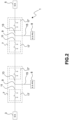
- the "T” junction 7 comprises a first switchgear unit 17 which allows grid reconfigurations and is installed on the first section 11.
- the "T” junction 7 further comprises a second switchgear unit 17' which allows grid reconfigurations and is installed on the second section 13.
- Each switchgear unit 17, 17' includes a plurality of switchgear unit poles 17A, 17B, 17C, each associated with a respective phase of the high-voltage overhead electric transmission line 1.
- switchgear unit pole refers to a system composed of several electrical switchgear devices, immersed in an insulating fluid, and enclosed within metal casings.
- the switchgear unit comprises the functions of circuit breaker, disconnector and, if necessary, ground disconnector in a single system.
- the activation of the aforesaid functions is motorized, with the possibility of manual handling in the absence of power supply.
- the maneuvering of the electrical switchgear equipment allows the switchgear unit to interrupt the no-load, nominal and short-circuit currents of the transmission line on which it is used, to disconnect (electrically isolate) the circuits connected upstream and downstream of the contacts, ensuring the isolation distances, or to establish electrical continuity therebetween.
- the switchgear unit is a system capable, therefore, of modifying the grid configuration, interrupting and re-establishing the electrical continuity in pre-established points of the High-Voltage grid, of extinguishing electrical faults and of carrying out safety measures by disconnecting and grounding system parts.
- the switchgear unit is configured as a compact and multifunctional system of the modular type on which additional modules, such as protection and power transformers, may be installed to perform all the functions typically present in a bay of an electrical substation.
- the switchgear units may be operated remotely, locally from a dedicated control panel or manually.
- Each switchgear unit pole 17A, 17B, 17C of the switchgear units 17, 17' comprises a line circuit breaker and at least one line disconnector.
- there are two line disconnectors in particular, a first line disconnector 52' upstream of the circuit breaker 50 of the switchgear unit pole and a second line disconnector 52" downstream of said circuit breaker 50, each of which is adapted to switch between a continuity condition of the line and a disconnection condition thereof, with further possibility of ground connection.
- the first switchgear unit 17 and the second switchgear unit 17' may be arranged at or near the three-section joint 9 of the "T" junction 7.
- the switchgear units 17, 17' could be installed on the ground near a tower of the electrical grid.
- this solution is expensive in terms of land consumption and, therefore, environmental sustainability.
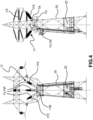
- the first and second switchgear units 17, 17' are each installed on the respective tower (20) of the electrical grid, specifically designed for this purpose.
- the high-voltage overhead electric transmission line may include, for each switchgear unit 17, 17' installed, a protection, command and control system functional to the management thereof for the operation of the transmission line sections connecting the first electrical substation 3 and the second electrical substation 5, wherein operation of the transmission line sections refers to the opening/closing, disconnecting and grounding of the system. Said actions may result in the interruption of the no-load, nominal or fault current (typically, for example, following a phase-to-ground fault) of the line.
- each switchgear unit may also be installed directly on the tower 20 on which the respective switchgear unit 17, 17', controlled by said protection, command and control system, is installed, and it may be placed, in particular, inside a kiosk 22.
- the kiosk 22 will be enclosed in the volume (space) already occupied by the structure of the lattice tower. Preferably, the kiosk is raised off the ground for safety reasons.
- the operational status of the switchgear units 17, 17' may be teleoperated remotely, and more precisely, by the control room of the grid operator in charge of the territory, through suitable equipment, arranged in at least one of the first electrical substation 3 and the second electrical substation 5, arranged at the ends of the high-voltage overhead electric transmission line 1.
- FIG. 6 An example of a graphic interface of a remote control system is schematically illustrated in Fig. 6 .
- the entire transmission line is represented in this interface and, in particular, the various switchgear units, the electrical substations from which the line departs and the junctions to active or passive users, or to further electric substations or primary substations are depicted.
- Line circuit breakers are indicated with squares and disconnectors with rhombuses. The operator may determine the open/closed status of the circuit breakers and disconnectors based on the color assumed by the respective rhombus or square. By clicking on said rhombus or square, the operator may change its operational status.
- the remote control systems may transmit to and receive signals from the protection, command and control system associated with each switchgear unit 17, 17' through respective optical fibers.
- each switchgear unit may comprise at least one current transformer TA, arranged for detecting the electric current of a phase of the high-voltage overhead electric transmission line 1, both in normal and fault conditions. These current detections are provided to allow monitoring of the line status and identification of the fault condition. Thus, it will then be possible to selectively extinguish said fault, by opening only the fault section without disconnecting the entire transmission line.
- TA current transformer
- each switchgear unit 17, 17' may comprise a device arranged to draw electrical power supply directly from a phase of the high-voltage transmission line 1 in order to supply power to the protection, command and control system associated with the respective switchgear unit, as well as the electrical switchgear equipment, forming said switchgear unit.
- Said device may be mounted directly on at least one switchgear unit pole 17A, 17B, 17C of a switchgear unit 17, 17' and may be obtained by means of an inductive power transformer TIP.
- each switchgear unit 17, 17' may also comprise a voltage transformer TV, arranged to detect the electric voltage of a phase of the high-voltage overhead electric transmission line 1, both in normal and fault conditions. Said electric voltage detections are provided to allow monitoring of the line status and identification of the fault condition. Thus, it will then be possible to selectively extinguish said fault, by opening only the fault section without disconnecting the entire transmission line.
- a voltage transformer TV arranged to detect the electric voltage of a phase of the high-voltage overhead electric transmission line 1, both in normal and fault conditions. Said electric voltage detections are provided to allow monitoring of the line status and identification of the fault condition. Thus, it will then be possible to selectively extinguish said fault, by opening only the fault section without disconnecting the entire transmission line.
- This voltage transformer may be an independent module or may be integrated in the inductive power transformer TIP.
- the voltage transformers may also be more than one and may be installed upstream and downstream of the circuit breaker of a switchgear unit pole 17A, 17B, 17C, to enable an electrical synchronism check between the upstream and downstream line section of the switchgear unit 17, 17', preliminary to the correct closing operation of the circuit breaker 50 of each switchgear unit pole 17A, 17B, 17C.
- each switchgear unit may be protected from impulse overvoltages due to lightning strikes or operation of electrical devices, by surge arresters LA, installed upstream and downstream of the switchgear unit.
- Said surge arresters LA may also be installed on the tower 20 on which the switchgear unit 17, 17' is installed, for example in a horizontal position.
- the advantage achieved is, therefore, that of having obtained a high-voltage overhead electric transmission line that reduces working time and the time-periods in which the transmission line remains disconnected in the event of maintenance and/or repair of any damage along said line, with a consequent reduction of indemnities and penalties requested from the transmission grid operator and reduction of the probability of damage to the users' plants resulting from the prolongation of the power interruption, during specific manufacture processes.
Landscapes
- Engineering & Computer Science (AREA)
- Power Engineering (AREA)
- Suspension Of Electric Lines Or Cables (AREA)
- Remote Monitoring And Control Of Power-Distribution Networks (AREA)
- Gas-Insulated Switchgears (AREA)
- Emergency Protection Circuit Devices (AREA)
Claims (14)
- Elektrische Hochspannungsfreileitung (1), die sich von einer ersten elektrischen Unterstation (3) zu einer zweiten elektrischen Unterstation (5) erstreckt, wobei die elektrische Hochspannungsfreileitung (1) mindestens eine "T" -Verzweigung (7) umfasst, die eine dreiteilige Verbindung (9) bildet, wobei ein erster Abschnitt (11) und ein zweiter Abschnitt (13) eingerichtet sind, um die Verbindung zwischen der ersten elektrischen Unterstation (3) und der zweiten elektrischen Unterstation (5) zu erlauben, und ein dritter Abschnitt (15) eingerichtet ist, um die Verbindung eines Benutzers oder einer dritten elektrischen Unterstation oder Primärunterstation (8) mit der elektrischen Hochspannungsfreileitung (1) zu erlauben;wobei die elektrische Hochspannungsfreileitung (1) bereitstellt, dass die mindestens eine "T"-Verzweigung (7) zwei Schaltgeräteeinheiten umfasst: eine erste Schaltgeräteeinheit (17), die eingerichtet ist, um Netzrekonfigurationen zu erlauben, und auf dem ersten Abschnitt (11) installiert ist, und eine zweite Schaltgeräteeinheit (17'), die eingerichtet ist, um Netzrekonfigurationen zu erlauben, und auf dem zweiten Abschnitt (13) installiert ist;wobei die erste Schaltgeräteeinheit (17) auf einem Volumen installiert ist, das von der Struktur eines ersten Masts der elektrischen Hochspannungsfreileitung (1) eingenommen ist, und die zweite Schaltgeräteeinheit (17') auf einem Volumen installiert ist, das von der Struktur eines zweiten Masts der elektrischen Hochspannungsfreileitung (1) eingenommen ist;wobei jede Schaltgeräteeinheit (17, 17') eine Vielzahl von Schaltgeräteeinheitspolen (17A, 17B, 17C) beinhaltet, die jeweils einer jeweiligen Phase der elektrischen Hochspannungsfreileitung (1) zugeordnet sind;jeder der Schaltgeräteeinheitpole (17A, 17B, 17C) einen Leitungsschutzschalter (50) und mindestens einen Leitungsunterbrecher (52', 52") umfasst.
- Elektrische Hochspannungsfreileitung nach Anspruch 1, die für jede installierte Schaltgeräteeinheit (17, 17') ein Schutz-, Befehls- und Steuerungssystem beinhaltet, das für die Verwaltung der Schaltanlage (17, 17') funktional ist, um die Abschnitte der Übertragungsleitung, die die erste elektrische Unterstation (3) und die zweite elektrische Unterstation (5) verbinden, zu betreiben.
- Elektrische Hochspannungsfreileitung nach Anspruch 2, wobei jedes jeder Schaltgeräteeinheit (17, 17') zugeordnete Schutz-, Befehls- und Steuerungssystem auch direkt auf dem Mast (20) installiert ist, auf dem die jeweilige von dem Schutz-, Befehls- und Steuerungssystem gesteuerte Schaltanlage (17, 17') installiert ist.
- Elektrische Hochspannungsfreileitung nach Anspruch 3, wobei jedes Schutz-, Befehls- und Steuerungssystem innerhalb eines jeweiligen Kiosks (22) installiert ist.
- Elektrische Hochspannungsfreileitung nach einem der vorstehenden Ansprüche, wobei der Betriebszustand jeder Schaltgeräteeinheit (17, 17') durch einen Kontrollraum eines Systembetreibers des Netzes, der für dieses Gebiet zuständig ist, durch Steuerausrüstungen, die sich in mindestens einer der ersten elektrischen Unterstation (3) und der zweiten elektrischen Unterstation (5) befinden, fernbedient und ferngesteuert ist.
- Elektrische Hochspannungsfreileitung nach Anspruch 5, wobei die Steuerausrüstung, die sich in mindestens einer der ersten elektrischen Unterstation (3) und der zweiten elektrischen Unterstation (5) befindet, eingerichtet ist, um Signale zu/von jedem Schutz-, Befehls- und Steuersystem, das jeder Schaltgeräteeinheit (17A, 17B) zugeordnet ist, über jeweilige optische Fasern zu senden und zu empfangen.
- Elektrische Hochspannungsfreileitung nach einem der vorstehenden Ansprüche, wobei jede Schaltgeräteeinheit (17, 17') mindestens einen induktiven Leistungstransformator (TIP) umfasst, der eingerichtet ist, um elektrische Leistung direkt aus einer Phase der Hochspannungsübertragungsleitung (1) zu entnehmen, um die elektrische Schaltgeräteausrüstung der Schaltgeräteeinheit und das dieser zugeordnete Schutz-, Befehls- und Steuersystem mit Leistung zu versorgen.
- Elektrische Hochspannungsfreileitung nach einem der vorstehenden Ansprüche, wobei die Leitungsunterbrecher (52) jedes der Pole (17A, 17B, 17C) der Schaltgeräteeinheit zwei sind:- ein erster Leitungsunterbrecher (52') stromaufwärts des Leitungsschutzschalters (50) des jeweiligen Schaltgeräteeinheitspols (17A, 17B, 17C); und- ein zweiter Leitungsunterbrecher (52") stromabwärts desselben Leitungsschutzschalters (50).
- Elektrische Hochspannungsfreileitung nach einem der vorstehenden Ansprüche, wobei der Leitungsunterbrecher (52) dazu angepasst ist, in einen Leitungsunterbrechungszustand mit einer weiteren Erdverbindung umzuschalten.
- Elektrische Hochspannungsübertragungsleitung nach einem der vorstehenden Ansprüche, wobei jede Schaltgeräteeinheit (17, 17') mindestens einen Stromwandler (TA) umfasst, der eingerichtet ist, um elektrischen Strom einer Phase der elektrischen Hochspannungsübertragungsleitung (1) sowohl unter normalen als auch unter Fehlerbedingungen zu erfassen; wobei diese elektrischen Strommessungen eingerichtet sind, um die Überwachung des Leitungszustands, die Identifizierung des Fehlerzustands und den Ort des Fehlers zu erlauben.
- Elektrische Hochspannungsfreileitung nach einem der vorstehenden Ansprüche, wobei jede Schaltgeräteeinheit (17, 17') auch mindestens einen ersten Spannungstransformator (TV) umfasst, der eingerichtet ist, um die elektrische Spannung einer Phase der elektrischen Hochspannungsfreileitung (1) sowohl unter normalen als auch unter Fehlerbedingungen zu erfassen; wobei diese elektrischen Spannungsmessungen eingerichtet sind, um die Überwachung des Leitungszustands, die Identifizierung des Fehlerzustands und den Ort des Fehlers zu erlauben.
- Elektrische Hochspannungsfreileitung nach Anspruch 11, wobei jede Schaltgeräteeinheit (17, 17') mindestens einen zweiten Spannungstransformator (TV) beinhaltet, der einem seiner eigenen Schaltgeräteeinheitspole (17A, 17B, 17C) zugeordnet ist;wobei der erste Spannungstransformator (TV) in Bezug auf den Leitungsschutzschalter (50) des Schaltgeräteinheitsepols an einem Ende des Schaltgeräteeinheitspols (17A, 17B, 17C), dem er zugeordnet ist, installiert ist, und der zweite Spannungstransformator (TV) an dem entgegengesetzten Ende des Schaltgeräteeinheitspols (17A, 17B, 17C), dem der erste Spannungstransformator (TV) zugeordnet ist, installiert ist;wobei der zweite Spannungstransformator (TV) eingerichtet ist, um eine elektrische Synchronitätsprüfung zwischen dem Leitungsabschnitt stromaufwärts und stromabwärts der Schaltgeräteeinheit vor dem korrekten Schließvorgang des Leistungsschalters (50) jedes Schaltgeräteeinheitspols (17A, 17B, 17C) zu ermöglichen.
- Elektrische Hochspannungsfreileitung nach Anspruch 11 und 12, wobei mindestens einer von dem ersten und zweiten Spannungstransformator (TV) in den induktiven Leistungstransformator (TIP) integriert ist.
- Hochspannungsfreileitung nach Anspruch 1, wobei jede Schaltgeräteeinheit (17, 17') gegen Überspannungen geschützt ist, indem stromaufwärts und stromabwärts davon Überspannungsableiter (LA) installiert sind, die auf demselben Mast installiert sind, auf dem die Schaltgeräteeinheit (17, 17') installiert ist.
Applications Claiming Priority (2)
| Application Number | Priority Date | Filing Date | Title |
|---|---|---|---|
| IT102019000018818A IT201900018818A1 (it) | 2019-10-15 | 2019-10-15 | Linea di trasmissione elettrica aerea ad alta tensione equipaggiata con unità di manovra |
| PCT/IB2020/059647 WO2021074812A1 (en) | 2019-10-15 | 2020-10-14 | High voltage overhead electric transmission line equipped with switchgear unit |
Publications (3)
| Publication Number | Publication Date |
|---|---|
| EP4046249A1 EP4046249A1 (de) | 2022-08-24 |
| EP4046249B1 true EP4046249B1 (de) | 2023-11-22 |
| EP4046249C0 EP4046249C0 (de) | 2023-11-22 |
Family
ID=69743719
Family Applications (1)
| Application Number | Title | Priority Date | Filing Date |
|---|---|---|---|
| EP20807106.8A Active EP4046249B1 (de) | 2019-10-15 | 2020-10-14 | Elektrische hochspannungsfreileitung, die mit einer schalteinheit ausgestattet ist |
Country Status (5)
| Country | Link |
|---|---|
| US (1) | US12283799B2 (de) |
| EP (1) | EP4046249B1 (de) |
| ES (1) | ES2967104T3 (de) |
| IT (1) | IT201900018818A1 (de) |
| WO (1) | WO2021074812A1 (de) |
Families Citing this family (5)
| Publication number | Priority date | Publication date | Assignee | Title |
|---|---|---|---|---|
| US12051889B2 (en) * | 2019-10-15 | 2024-07-30 | Terna S.P.A. | Tower, particularly for a high-voltage overhead electric transmission line, equipped with switchgear unit and related protection, command and control system |
| US11990733B2 (en) * | 2019-12-23 | 2024-05-21 | Terna S.P.A. | Compact electric switching substation into a lattice tower for connection of active and passive users to a high-voltage electric grid and use of said substation for connecting an electric vehicle charging station to a high-voltage electric grid |
| CN113295910B (zh) * | 2021-05-14 | 2022-06-03 | 国网安徽省电力有限公司马鞍山供电公司 | 一种分体式钳式电流互感器及变电站线路测绘方法 |
| CN114843918A (zh) * | 2022-03-02 | 2022-08-02 | 广东电网有限责任公司 | 一种hgis设备的布置结构 |
| US20230369864A1 (en) * | 2022-05-13 | 2023-11-16 | G & W Electric Company | Microgrid |
Family Cites Families (18)
| Publication number | Priority date | Publication date | Assignee | Title |
|---|---|---|---|---|
| US4379957A (en) * | 1981-01-14 | 1983-04-12 | Westinghouse Electric Corp. | Modular "Y"-type enclosure elements for gas insulated substations |
| US5515230A (en) * | 1990-09-06 | 1996-05-07 | Ashley; James R. | Poly-phase coaxial power line efficiency enhancements |
| JP3432462B2 (ja) * | 1999-08-27 | 2003-08-04 | 三菱電機株式会社 | 架空送電線路のt分岐構造 |
| US6630638B1 (en) * | 2000-05-26 | 2003-10-07 | Abb Inc. | Dead tank drawout breakers |
| FR2815784B1 (fr) * | 2000-10-20 | 2003-01-17 | Alstom | Poste haute tension hybride a depart opposes en vis a vis, et modules blindes de coupure et d'aiguillage pour un tel poste |
| US6411067B1 (en) * | 2001-02-20 | 2002-06-25 | Abb Ab | Voltage source converters operating either as back-to-back stations or as parallel static var compensators |
| CA2409284A1 (fr) * | 2002-10-22 | 2004-04-22 | Hydro Quebec | Appareil et methode de commutation pour controler l'ecoulement de puissance dans une ligne de phase d'un troncon d'une ligne de transport d'energie electrique |
| DE10331744A1 (de) * | 2003-07-11 | 2005-02-10 | IAD Gesellschaft für Informatik, Automatisierung und Datenverarbeitung mbH | Induktive Ankoppelschaltung und Verfahren zur Nachrichtenübertragung in elektrischen Energieverteilnetzen |
| EP1580856B1 (de) * | 2004-03-25 | 2012-06-20 | ABB Technology AG | Hochspannungsschaltanlage in Freiluftbauweise |
| CA2469778A1 (en) * | 2004-06-04 | 2005-12-04 | Pierre Couture | Switching modules for the extraction/injection of power (without ground or phase reference) from a bundled hv line |
| CN103703653B (zh) * | 2011-07-22 | 2018-04-20 | 魁北克水电公司 | 用于改变相位线的阻抗的开关设备、控制系统和方法 |
| ES2606178T3 (es) * | 2012-01-19 | 2017-03-23 | HYDRO-QUéBEC | Dispositivo para un aparato de conmutación de exterior |
| US20130258724A1 (en) * | 2012-03-28 | 2013-10-03 | General Electric Company | High voltage direct current system |
| FR3026239B1 (fr) * | 2014-09-23 | 2016-10-14 | Schneider Electric Ind Sas | Appareillage de protection electrique moyenne tension a comptage du courant |
| US10096978B2 (en) * | 2016-11-03 | 2018-10-09 | Eaton Intelligent Power Limited | Mountable electrical system |
| EP3662553A1 (de) * | 2017-08-04 | 2020-06-10 | ABB Power Grids Switzerland AG | Verfahren und vorrichtung zur identifizierung eines fehlerhaften abschnitts in mischleitungen mit mehreren anschlüssen |
| US10880362B2 (en) * | 2018-12-03 | 2020-12-29 | Intel Corporation | Virtual electrical networks |
| EP3745547B1 (de) * | 2019-05-31 | 2023-02-15 | Hitachi Energy Switzerland AG | Anordnung mit einer turmmontierte hochspannungs-schaltanlage und einem hochspannungs-turm |
-
2019
- 2019-10-15 IT IT102019000018818A patent/IT201900018818A1/it unknown
-
2020
- 2020-10-14 EP EP20807106.8A patent/EP4046249B1/de active Active
- 2020-10-14 WO PCT/IB2020/059647 patent/WO2021074812A1/en not_active Ceased
- 2020-10-14 ES ES20807106T patent/ES2967104T3/es active Active
- 2020-10-14 US US17/768,913 patent/US12283799B2/en active Active
Also Published As
| Publication number | Publication date |
|---|---|
| WO2021074812A1 (en) | 2021-04-22 |
| US20240106208A1 (en) | 2024-03-28 |
| EP4046249A1 (de) | 2022-08-24 |
| IT201900018818A1 (it) | 2021-04-15 |
| US12283799B2 (en) | 2025-04-22 |
| ES2967104T3 (es) | 2024-04-26 |
| EP4046249C0 (de) | 2023-11-22 |
Similar Documents
| Publication | Publication Date | Title |
|---|---|---|
| US12283799B2 (en) | High voltage overhead electric transmission line equipped with switchgear unit | |
| EP2633597B1 (de) | Spannungsausgleich symmetrischer einpoliger hvdc-übertragungsleitungen nach erdfehlern | |
| CN204012678U (zh) | 一种配电网多模接地保护系统 | |
| CN106655120A (zh) | 配电网中性点智能接地保护方法与系统 | |
| SE539916C2 (sv) | Metod och anordning för bortkoppling av fel i elnät | |
| CN101505053B (zh) | 一种基于用户分界断路器成套装置的配电网线路保护方法 | |
| CN103837798B (zh) | 配电网单相接地故障性质的快速诊断装置 | |
| CN106786473A (zh) | 一种消弧线圈接地系统配网线路单相接地故障隔离方法 | |
| CN202586308U (zh) | 微机综合接地保护装置 | |
| JP5442675B2 (ja) | 絶縁抵抗測定システム | |
| CN204651919U (zh) | 一种10kV电网中性点联合接地装置 | |
| EP4046250B1 (de) | Stromturm für eine hochspannungsfreileitung, mit einer schaltanlage und einem entsprechenden schutz-, befehls- und steuersystem | |
| CN203883464U (zh) | 可控型小电阻消弧装置 | |
| CN110212511B (zh) | 基于电阻异地自动投切的66kV消弧线圈接地系统 | |
| CN214755500U (zh) | 一种用于中性点不接地电力系统的保护系统 | |
| CN205790973U (zh) | 变压器‑线路单元接线的供电系统 | |
| CN103560501A (zh) | 可控型小电阻消弧装置和方法 | |
| CN214755490U (zh) | 非有效接地柴油发电机组中性点保护装置 | |
| KR102613905B1 (ko) | 계전기 | |
| KR100532925B1 (ko) | 배전자동화기반의 비접지계 지락고장구간 검출방법 | |
| CN219554656U (zh) | 一种检修电源配电优化设备 | |
| CN109921405A (zh) | 一种中压系统中性点的接地方法 | |
| KR102617698B1 (ko) | 충전식 직류공급기기가 내장된 가스절연개폐장치 | |
| CN112202171B (zh) | 一种负载接入设备和供负载接入的电力线贯通方法 | |
| EP4047763B1 (de) | Schaltanlage für stromerzeugungssysteme |
Legal Events
| Date | Code | Title | Description |
|---|---|---|---|
| STAA | Information on the status of an ep patent application or granted ep patent |
Free format text: STATUS: UNKNOWN |
|
| STAA | Information on the status of an ep patent application or granted ep patent |
Free format text: STATUS: THE INTERNATIONAL PUBLICATION HAS BEEN MADE |
|
| PUAI | Public reference made under article 153(3) epc to a published international application that has entered the european phase |
Free format text: ORIGINAL CODE: 0009012 |
|
| STAA | Information on the status of an ep patent application or granted ep patent |
Free format text: STATUS: REQUEST FOR EXAMINATION WAS MADE |
|
| 17P | Request for examination filed |
Effective date: 20220506 |
|
| AK | Designated contracting states |
Kind code of ref document: A1 Designated state(s): AL AT BE BG CH CY CZ DE DK EE ES FI FR GB GR HR HU IE IS IT LI LT LU LV MC MK MT NL NO PL PT RO RS SE SI SK SM TR |
|
| DAV | Request for validation of the european patent (deleted) | ||
| DAX | Request for extension of the european patent (deleted) | ||
| REG | Reference to a national code |
Ref legal event code: R079 Ipc: H02J0003200000 Ref country code: DE Ref legal event code: R079 Ref document number: 602020021611 Country of ref document: DE Free format text: PREVIOUS MAIN CLASS: H02B0005000000 Ipc: H02J0003200000 |
|
| GRAP | Despatch of communication of intention to grant a patent |
Free format text: ORIGINAL CODE: EPIDOSNIGR1 |
|
| STAA | Information on the status of an ep patent application or granted ep patent |
Free format text: STATUS: GRANT OF PATENT IS INTENDED |
|
| RIC1 | Information provided on ipc code assigned before grant |
Ipc: H02G 7/20 20060101ALI20230711BHEP Ipc: H02B 5/02 20060101ALI20230711BHEP Ipc: H02J 13/00 20060101ALI20230711BHEP Ipc: H02J 3/00 20060101ALI20230711BHEP Ipc: H02J 3/20 20060101AFI20230711BHEP |
|
| INTG | Intention to grant announced |
Effective date: 20230724 |
|
| GRAS | Grant fee paid |
Free format text: ORIGINAL CODE: EPIDOSNIGR3 |
|
| GRAA | (expected) grant |
Free format text: ORIGINAL CODE: 0009210 |
|
| STAA | Information on the status of an ep patent application or granted ep patent |
Free format text: STATUS: THE PATENT HAS BEEN GRANTED |
|
| AK | Designated contracting states |
Kind code of ref document: B1 Designated state(s): AL AT BE BG CH CY CZ DE DK EE ES FI FR GB GR HR HU IE IS IT LI LT LU LV MC MK MT NL NO PL PT RO RS SE SI SK SM TR |
|
| REG | Reference to a national code |
Ref country code: GB Ref legal event code: FG4D |
|
| REG | Reference to a national code |
Ref country code: CH Ref legal event code: EP |
|
| REG | Reference to a national code |
Ref country code: DE Ref legal event code: R096 Ref document number: 602020021611 Country of ref document: DE |
|
| REG | Reference to a national code |
Ref country code: IE Ref legal event code: FG4D |
|
| U01 | Request for unitary effect filed |
Effective date: 20231215 |
|
| U07 | Unitary effect registered |
Designated state(s): AT BE BG DE DK EE FI FR IT LT LU LV MT NL PT SE SI Effective date: 20231215 |
|
| PG25 | Lapsed in a contracting state [announced via postgrant information from national office to epo] |
Ref country code: GR Free format text: LAPSE BECAUSE OF FAILURE TO SUBMIT A TRANSLATION OF THE DESCRIPTION OR TO PAY THE FEE WITHIN THE PRESCRIBED TIME-LIMIT Effective date: 20240223 |
|
| PG25 | Lapsed in a contracting state [announced via postgrant information from national office to epo] |
Ref country code: IS Free format text: LAPSE BECAUSE OF FAILURE TO SUBMIT A TRANSLATION OF THE DESCRIPTION OR TO PAY THE FEE WITHIN THE PRESCRIBED TIME-LIMIT Effective date: 20240322 |
|
| REG | Reference to a national code |
Ref country code: ES Ref legal event code: FG2A Ref document number: 2967104 Country of ref document: ES Kind code of ref document: T3 Effective date: 20240426 |
|
| PG25 | Lapsed in a contracting state [announced via postgrant information from national office to epo] |
Ref country code: IS Free format text: LAPSE BECAUSE OF FAILURE TO SUBMIT A TRANSLATION OF THE DESCRIPTION OR TO PAY THE FEE WITHIN THE PRESCRIBED TIME-LIMIT Effective date: 20240322 Ref country code: GR Free format text: LAPSE BECAUSE OF FAILURE TO SUBMIT A TRANSLATION OF THE DESCRIPTION OR TO PAY THE FEE WITHIN THE PRESCRIBED TIME-LIMIT Effective date: 20240223 |
|
| PG25 | Lapsed in a contracting state [announced via postgrant information from national office to epo] |
Ref country code: RS Free format text: LAPSE BECAUSE OF FAILURE TO SUBMIT A TRANSLATION OF THE DESCRIPTION OR TO PAY THE FEE WITHIN THE PRESCRIBED TIME-LIMIT Effective date: 20231122 Ref country code: PL Free format text: LAPSE BECAUSE OF FAILURE TO SUBMIT A TRANSLATION OF THE DESCRIPTION OR TO PAY THE FEE WITHIN THE PRESCRIBED TIME-LIMIT Effective date: 20231122 Ref country code: NO Free format text: LAPSE BECAUSE OF FAILURE TO SUBMIT A TRANSLATION OF THE DESCRIPTION OR TO PAY THE FEE WITHIN THE PRESCRIBED TIME-LIMIT Effective date: 20240222 Ref country code: HR Free format text: LAPSE BECAUSE OF FAILURE TO SUBMIT A TRANSLATION OF THE DESCRIPTION OR TO PAY THE FEE WITHIN THE PRESCRIBED TIME-LIMIT Effective date: 20231122 |
|
| PG25 | Lapsed in a contracting state [announced via postgrant information from national office to epo] |
Ref country code: CZ Free format text: LAPSE BECAUSE OF FAILURE TO SUBMIT A TRANSLATION OF THE DESCRIPTION OR TO PAY THE FEE WITHIN THE PRESCRIBED TIME-LIMIT Effective date: 20231122 |
|
| PG25 | Lapsed in a contracting state [announced via postgrant information from national office to epo] |
Ref country code: SK Free format text: LAPSE BECAUSE OF FAILURE TO SUBMIT A TRANSLATION OF THE DESCRIPTION OR TO PAY THE FEE WITHIN THE PRESCRIBED TIME-LIMIT Effective date: 20231122 |
|
| PG25 | Lapsed in a contracting state [announced via postgrant information from national office to epo] |
Ref country code: SM Free format text: LAPSE BECAUSE OF FAILURE TO SUBMIT A TRANSLATION OF THE DESCRIPTION OR TO PAY THE FEE WITHIN THE PRESCRIBED TIME-LIMIT Effective date: 20231122 Ref country code: SK Free format text: LAPSE BECAUSE OF FAILURE TO SUBMIT A TRANSLATION OF THE DESCRIPTION OR TO PAY THE FEE WITHIN THE PRESCRIBED TIME-LIMIT Effective date: 20231122 Ref country code: RO Free format text: LAPSE BECAUSE OF FAILURE TO SUBMIT A TRANSLATION OF THE DESCRIPTION OR TO PAY THE FEE WITHIN THE PRESCRIBED TIME-LIMIT Effective date: 20231122 Ref country code: CZ Free format text: LAPSE BECAUSE OF FAILURE TO SUBMIT A TRANSLATION OF THE DESCRIPTION OR TO PAY THE FEE WITHIN THE PRESCRIBED TIME-LIMIT Effective date: 20231122 |
|
| REG | Reference to a national code |
Ref country code: DE Ref legal event code: R097 Ref document number: 602020021611 Country of ref document: DE |
|
| PLBE | No opposition filed within time limit |
Free format text: ORIGINAL CODE: 0009261 |
|
| STAA | Information on the status of an ep patent application or granted ep patent |
Free format text: STATUS: NO OPPOSITION FILED WITHIN TIME LIMIT |
|
| 26N | No opposition filed |
Effective date: 20240823 |
|
| U20 | Renewal fee for the european patent with unitary effect paid |
Year of fee payment: 5 Effective date: 20241016 |
|
| PG25 | Lapsed in a contracting state [announced via postgrant information from national office to epo] |
Ref country code: MC Free format text: LAPSE BECAUSE OF FAILURE TO SUBMIT A TRANSLATION OF THE DESCRIPTION OR TO PAY THE FEE WITHIN THE PRESCRIBED TIME-LIMIT Effective date: 20231122 |
|
| PG25 | Lapsed in a contracting state [announced via postgrant information from national office to epo] |
Ref country code: IE Free format text: LAPSE BECAUSE OF NON-PAYMENT OF DUE FEES Effective date: 20241014 |
|
| REG | Reference to a national code |
Ref country code: CH Ref legal event code: U11 Free format text: ST27 STATUS EVENT CODE: U-0-0-U10-U11 (AS PROVIDED BY THE NATIONAL OFFICE) Effective date: 20251101 |
|
| U20 | Renewal fee for the european patent with unitary effect paid |
Year of fee payment: 6 Effective date: 20251016 |
|
| PGFP | Annual fee paid to national office [announced via postgrant information from national office to epo] |
Ref country code: GB Payment date: 20251022 Year of fee payment: 6 |
|
| PGFP | Annual fee paid to national office [announced via postgrant information from national office to epo] |
Ref country code: CH Payment date: 20251101 Year of fee payment: 6 |
|
| PG25 | Lapsed in a contracting state [announced via postgrant information from national office to epo] |
Ref country code: CY Free format text: LAPSE BECAUSE OF FAILURE TO SUBMIT A TRANSLATION OF THE DESCRIPTION OR TO PAY THE FEE WITHIN THE PRESCRIBED TIME-LIMIT; INVALID AB INITIO Effective date: 20201014 |
|
| PGFP | Annual fee paid to national office [announced via postgrant information from national office to epo] |
Ref country code: ES Payment date: 20251216 Year of fee payment: 6 |
|
| PG25 | Lapsed in a contracting state [announced via postgrant information from national office to epo] |
Ref country code: HU Free format text: LAPSE BECAUSE OF FAILURE TO SUBMIT A TRANSLATION OF THE DESCRIPTION OR TO PAY THE FEE WITHIN THE PRESCRIBED TIME-LIMIT; INVALID AB INITIO Effective date: 20201014 |