EP4046474B1 - Erntemaschine mit vorwärtssteuerung von füllmechanismen - Google Patents
Erntemaschine mit vorwärtssteuerung von füllmechanismen Download PDFInfo
- Publication number
- EP4046474B1 EP4046474B1 EP22154037.0A EP22154037A EP4046474B1 EP 4046474 B1 EP4046474 B1 EP 4046474B1 EP 22154037 A EP22154037 A EP 22154037A EP 4046474 B1 EP4046474 B1 EP 4046474B1
- Authority
- EP
- European Patent Office
- Prior art keywords
- turn
- spout
- harvester
- flap
- location
- Prior art date
- Legal status (The legal status is an assumption and is not a legal conclusion. Google has not performed a legal analysis and makes no representation as to the accuracy of the status listed.)
- Active
Links
Images



Classifications
-
- A—HUMAN NECESSITIES
- A01—AGRICULTURE; FORESTRY; ANIMAL HUSBANDRY; HUNTING; TRAPPING; FISHING
- A01D—HARVESTING; MOWING
- A01D43/00—Mowers combined with apparatus performing additional operations while mowing
- A01D43/06—Mowers combined with apparatus performing additional operations while mowing with means for collecting, gathering or loading mown material
- A01D43/07—Mowers combined with apparatus performing additional operations while mowing with means for collecting, gathering or loading mown material in or into a trailer
- A01D43/073—Mowers combined with apparatus performing additional operations while mowing with means for collecting, gathering or loading mown material in or into a trailer with controllable discharge spout
-
- A—HUMAN NECESSITIES
- A01—AGRICULTURE; FORESTRY; ANIMAL HUSBANDRY; HUNTING; TRAPPING; FISHING
- A01D—HARVESTING; MOWING
- A01D41/00—Combines, i.e. harvesters or mowers combined with threshing devices
- A01D41/12—Details of combines
- A01D41/127—Control or measuring arrangements specially adapted for combines
-
- A—HUMAN NECESSITIES
- A01—AGRICULTURE; FORESTRY; ANIMAL HUSBANDRY; HUNTING; TRAPPING; FISHING
- A01D—HARVESTING; MOWING
- A01D43/00—Mowers combined with apparatus performing additional operations while mowing
- A01D43/08—Mowers combined with apparatus performing additional operations while mowing with means for cutting up the mown crop, e.g. forage harvesters
- A01D43/086—Mowers combined with apparatus performing additional operations while mowing with means for cutting up the mown crop, e.g. forage harvesters and means for collecting, gathering or loading mown material
- A01D43/087—Mowers combined with apparatus performing additional operations while mowing with means for cutting up the mown crop, e.g. forage harvesters and means for collecting, gathering or loading mown material with controllable discharge spout
-
- A—HUMAN NECESSITIES
- A01—AGRICULTURE; FORESTRY; ANIMAL HUSBANDRY; HUNTING; TRAPPING; FISHING
- A01D—HARVESTING; MOWING
- A01D61/00—Elevators or conveyors for binders or combines
-
- A—HUMAN NECESSITIES
- A01—AGRICULTURE; FORESTRY; ANIMAL HUSBANDRY; HUNTING; TRAPPING; FISHING
- A01F—PROCESSING OF HARVESTED PRODUCE; HAY OR STRAW PRESSES; DEVICES FOR STORING AGRICULTURAL OR HORTICULTURAL PRODUCE
- A01F12/00—Parts or details of threshing apparatus
- A01F12/46—Mechanical grain conveyors
-
- G—PHYSICS
- G05—CONTROLLING; REGULATING
- G05D—SYSTEMS FOR CONTROLLING OR REGULATING NON-ELECTRIC VARIABLES
- G05D1/00—Control of position, course, altitude or attitude of land, water, air or space vehicles, e.g. using automatic pilots
- G05D1/02—Control of position or course in two dimensions
- G05D1/021—Control of position or course in two dimensions specially adapted to land vehicles
- G05D1/0287—Control of position or course in two dimensions specially adapted to land vehicles involving a plurality of land vehicles, e.g. fleet or convoy travelling
- G05D1/0291—Fleet control
- G05D1/0293—Convoy travelling
-
- G—PHYSICS
- G05—CONTROLLING; REGULATING
- G05D—SYSTEMS FOR CONTROLLING OR REGULATING NON-ELECTRIC VARIABLES
- G05D1/00—Control of position, course, altitude or attitude of land, water, air or space vehicles, e.g. using automatic pilots
- G05D1/60—Intended control result
- G05D1/656—Interaction with payloads or external entities
- G05D1/667—Delivering or retrieving payloads
-
- G—PHYSICS
- G05—CONTROLLING; REGULATING
- G05D—SYSTEMS FOR CONTROLLING OR REGULATING NON-ELECTRIC VARIABLES
- G05D1/00—Control of position, course, altitude or attitude of land, water, air or space vehicles, e.g. using automatic pilots
- G05D1/60—Intended control result
- G05D1/69—Coordinated control of the position or course of two or more vehicles
- G05D1/695—Coordinated control of the position or course of two or more vehicles for maintaining a fixed relative position of the vehicles, e.g. for convoy travelling or formation flight
-
- G—PHYSICS
- G05—CONTROLLING; REGULATING
- G05D—SYSTEMS FOR CONTROLLING OR REGULATING NON-ELECTRIC VARIABLES
- G05D1/00—Control of position, course, altitude or attitude of land, water, air or space vehicles, e.g. using automatic pilots
- G05D1/0011—Control of position, course, altitude or attitude of land, water, air or space vehicles, e.g. using automatic pilots associated with a remote control arrangement
- G05D1/0027—Control of position, course, altitude or attitude of land, water, air or space vehicles, e.g. using automatic pilots associated with a remote control arrangement involving a plurality of vehicles, e.g. fleet or convoy travelling
-
- G—PHYSICS
- G05—CONTROLLING; REGULATING
- G05D—SYSTEMS FOR CONTROLLING OR REGULATING NON-ELECTRIC VARIABLES
- G05D1/00—Control of position, course, altitude or attitude of land, water, air or space vehicles, e.g. using automatic pilots
- G05D1/60—Intended control result
- G05D1/69—Coordinated control of the position or course of two or more vehicles
- G05D1/692—Coordinated control of the position or course of two or more vehicles involving a plurality of disparate vehicles
Definitions
- the present description relates to harvesting machines. More specifically, the present description relates to automatically performing feed forward control when filling a receiving vehicle.
- Some vehicles include harvesters, such as forage harvesters, sugar cane harvesters, combine harvesters, and other harvesters, that harvest grain or other crop. Such harvesters often unload into carts which may be pulled by tractors or semi-trailers as the harvesters are moving.
- a semi-truck or tractor-pulled cart is often in position relative to the forage harvester (e.g., behind the forage harvester or alongside the forage harvester) so that the forage harvester can fill the truck or cart while moving through the field.
- this requires the operator of the forage harvester to control the position of the unloading spout and flap so that the truck or cart is filled evenly, but not overfilled.
- Even a momentary misalignment between the spout and the truck or cart may result in hundreds of pounds of harvested material being dumped on the ground, or elsewhere, rather than in the truck or cart.
- an agricultural harvester has a frame and a spout that is movably mounted relative to the frame.
- a spout actuator drives movement of the spout relative to the frame based on a spout actuator control signal.
- Harvesting functionality engages material from a field and delivers the material through an outlet end of the spout as the agricultural harvester moves through the field in a direction of travel.
- a turn identifier identifies a location of a turn forward of the agricultural harvester in the direction of travel and generates a turn location indicator indicative of the location of the turn.
- a speed detector detects a speed of the agricultural harvester and generates a speed indicator indicative of the detected speed.
- a position compensation control system generates spout position compensation information for controlling the spout actuator based on the turn location indicator and the speed indicator.
- the position compensation control system is configured to send the spout position compensation information to the spout position controller prior to the agricultural harvester executing the turn.
- a spout position controller is configured to generate the spout actuator control signal to control the spout actuator based on the spout position compensation information.
- the turn identifier comprises a turn angle identifier configured to identify a characteristic indicative of an angle of the turn and generates a turn angle indicator based on the angle of the turn, the position compensation control system configured to generate the spout position compensation information for controlling the spout actuator based on the turn angle indicator.
- FIG. 1 is a pictorial illustration showing one example of a self-propelled forage harvester 100 filling a tractor-pulled grain cart (or receiving vehicle) 102.
- Cart 102 thus defines an interior that forms a receiving vessel 103 for receiving harvested material through a receiving area 112.
- a tractor 104 that is pulling grain cart 102, is positioned directly behind forage harvester 100.
- forage harvester 100 has a camera 106 mounted on the spout 108 through which the harvested material 110 is traveling.
- the spout 108 can be pivotally or rotationally mounted to a frame 107 of harvester 100.
- Camera 106 captures an image of the receiving area 112 of cart 102.
- the receiving area 112 is defined by an upper edge of the walls of cart 102.
- harvester 100 has an automatic cart fill control system that includes image processing, as discussed above, that system can gauge the height of harvested material in cart 102, and the location of that material. The system thus automatically controls the position of spout 108 and flap 109 to direct the trajectory of material 110 into the receiving area 112 of cart 102 to obtain an even fill throughout the entire length and width of cart 102, while not overfilling cart 102.
- automatically it is meant, for example, that the operation is performed without further human involvement except, perhaps, to initiate or authorize the operation.
- harvester 100 turns (such as to follow a curved windrow or curved crop rows or to make a headland turn), this can drastically and quickly change the position of the outlet end 111 of spout 108 relative to the receiving vessel 103, in cart 102.
- the relative change in position can often happen so fast that an automatic fill control system that automatically positions spout 108 and flap 109 cannot react quickly enough to compensate for the change in position, resulting in harvested material 110 being dumped on the ground, or being directed at tractor 104, or entering cart 102 at an undesired position.
- a forward looking device 116 is mounted to detect an image of an area 117 of the crop or windrow ahead of harvester 100 in the direction of travel. By analyzing the image, upcoming turns can be identified before harvester 100 even begins the turns. Thus, feed forward control signals can be generated to control the position of spout 108 and flap 109 to compensate for the turn. In this way, less crop is lost and a more accurate fill operation can be performed.
- forward looking device 116 can be used with a control system to control the position of spout 108 and flap 109 based on upcoming turns. For instance, the spout 108 and flap 109 can be controlled to continue filling at the current landing point during the turn. This can greatly relieve the operator of the burden of trying to control spout 108 and flap 109 while also trying to control harvester 100 to navigate a turn.
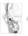
- FIG. 2 is a pictorial illustration showing another example of a self-propelled forage harvester 100, this time loading a semi-trailer (or receiving vessel on a receiving vehicle) 122 in a configuration in which a semi-tractor is pulling semi-trailer 122 alongside forage harvester 100. Therefore, the spout 108 and flap 109 are positioned to unload the harvested material 110 to fill trailer 122 according to a pre-defined side-by-side fill strategy.
- FIG. 2 shows that camera 106 can capture an image of semi-trailer 122. In the example illustrated in FIG.
- the field of view of camera 106 is directed toward the receiving area 120 of trailer 122 so that image processing can be performed to identify a landing point for the harvested material in trailer 122.
- image processing can be performed to identify a landing point for the harvested material in trailer 122.
- forward looking device 116 can be used on harvester 100 to identify upcoming turns so that spout 108 and flap 109 can be controlled in a feed forward way (before harvester 100 actually begins to execute a turn) to compensate for turns.
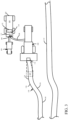
- FIG. 3 is a pictorial illustration of a top view of one example of harvester 100, towing vehicle 104 and cart 102.
- towing vehicle 104 is towing cart 102 alongside harvester 100, and harvester 100 is following a windrow 130.
- FIG. 3 also shows another, unharvested, windrow 132 in the field. It can be seen that windrow 130 begins a turn at a location 134 and ends the turn at a location 136. Windrow 130 again turns beginning at a location 138 and ending at a location 140.
- FIG. 3 also shows forward-looking device 116 that is capturing an image of an area 117 in front of harvester 100 in the direction of travel.
- harvester 100 As harvester 100 travels along windrow 130, it reaches the beginning of the first turn at 134 and begins to turn to the left. This causes spout 108 to swing to the left relatively quickly, because the turn beginning at location 137 is at an angle and the angular movement of the end 110 of the spout 108 is amplified by the length of spout 108. Thus, when the harvester 100 executes the turn, this quickly changes the position of the outlet end 111 of spout 108 relative to the receiving vessel 103 defined by cart 102. If harvester 100 is not equipped with an automatic fill control system, then this means that the operator of harvester 100 and the operator of tractor 104 must coordinate to ensure that the harvested material continues to go into vessel 103, and is not dumped on the ground. This can be very difficult, and the problem is exacerbated by the fact that both operators are attempting to navigate a turn, at roughly the same time.
- some active fill control systems allow the filling operation to be performed according to a pre-defined or selected fill strategy.
- Some such fill strategies include a front-to-back strategy, where the front of receiving vessel 103 is filled first and then the desired landing point 142 is moved rearwardly in receiving vessel 103, where filling continues. This filling operation continues, using the front-to-back strategy, until the entire receiving vessel 103 is evenly filled.
- Another strategy, similar to the front-to-back fill strategy is the back-to-front fill strategy. According to the back-to-front fill strategy, filling begins in the rear of receiving vessel 103 and proceeds to the front of receiving vessel 103.
- this type of active fill control system is reactive, it may not be able to compensate for a quick and significant change in the position of spout 108 relative to the position of receiving vessel 103, which can happen during turns. Thus, even if material is not dumped on the ground during a turn, the system still may be unable to perform the fill operation according to the selected fill strategy.
- Harvester 100 thus includes forward-looking device 116 which senses an area (e.g., captures an image of an area) 117 in front of harvester 100, in the direction of travel.
- Device 116 can be a camera, a stereo camera, a LIDAR sensor, a RADAR sensor, or another type of sensor which can generate information indicative of the location of windrow 130.
- a control system on harvester 100 processes the image or sensor data generated from area 117 to identify the location 134 where the turn begins, the angle of the turn, and the speed of harvester 100. As harvester 100 continues along windrow 130, the control system can also identify the location 136 where the turn ends.
- the control system can determine what control signals it needs to generate, and when it needs to generate them, in order to control the position of spout 108 and flap 111, as harvester 100 makes the turn, so that the harvested material continues to be deposited in receiving vessel 103 at the desired landing point 142.
- the desired landing point 142 may be the point where the harvested material is landing based on an operator or other input that positions spout 108 and flap 109.
- the control system continues to generate control signals so that the harvested material is deposited in the desired landing position, while harvester 100 makes the turn beginning at location 134 and ending at location 136. Because the control system in harvester 100 identifies, ahead of time, where the turn begins, the angle of the turn, and the speed of harvester 100, the control system can begin controlling the actuators that drive the position of spout 108 and flap 109 a sufficient amount of time prior to harvester 100 beginning the turn so that the harvested material is continuously deposited in receiving vessel 103, and at the desired landing point 142.
- the windrows 130 and 132 are generated by a prior pass of a windrower machine.
- the windrower machine can use a geographic position sensor (such as a Global Navigation Satellite System - GNSS - receiver, or another positioning system) to generate a map indicating the location of the windrows 130 and 132.
- the control system of harvester 100 can obtain the map and identify where turns are about to occur in the windrow based on the map and the current position of harvester 100 and use that information to generate feed forward control signals to control the actuators that drive positioning of spout 108 and flap 109.
- Other ways of identifying the location of the turn, and the angle of the turn can be used as well.
- control system can be used where harvester 100 is harvesting a crop (such as corn or beans), instead of following a windrow.
- the area 117 that is sensed by forward-looking device 116 can be used to detect the location and orientation of the crop rows, or the edge of the unharvested crop (such as in the case of a sugarcane harvester) and the direction and orientation of the crop rows or the edge of the harvested crop ahead of harvester 100 can be used to determine when harvester 100 is about to turn.
- the location and angle of the turn can be used to generate feed forward control signals to control the actuators that drive positioning of spout 108 and flap 109.
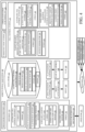
- FIG. 4 is a block diagram showing one example of agricultural harvester 100. Some of the items are similar to those shown in FIGS. 1-3 , and they are similarly numbered.
- harvester 100 can include one or more processors or servers 150, data store 152, sensors 154, fill control system 155 (which can include feed forward position compensation control system 220, target heading identification system 156, output generator 230, automatic fill control system 160, and other items 232), operator interface mechanisms 158, spout position controller 162, flap position controller 164, one or more spout actuators 166 and flap actuators 168, communication system 169, and other harvester functionality 170.
- FIG. 4 also shows that operator 172 can interact with one or more operator interface mechanisms 158 in order to control and manipulate agricultural harvester 100.
- FIG. 4 also shows that harvester 100 can communicate over network 174 with receiving vehicle 102, towing vehicle 104, and other systems 176.
- Sensors 154 can include automatic fill control sensors 180 (which themselves can include camera 106 and other automatic fill control sensors 182), spout position sensor 184, flap position sensor 186, geographic position sensor 188, forward-looking device 116, (which can include camera 190 or other forward-looking perception sensors 192), machine speed sensor 194, and other items 196.
- Data store 152 can include active fill control algorithms 198, and one or more prior maps 200.
- Prior maps 200 can include a prior pass map 202 that maps prior passes through the field by harvester 100, prior operation map 204 that has a map generated during a prior operation in the field other than the harvesting operation being performed by harvester 100, and prior year map 206 that includes a map generated during an operation performed during a prior growing year.
- Prior map 200 can also include other prior maps 208, which may include satellite maps or other aerial image maps (such as maps generated from images taken by an unmanned or manned aerial vehicle), or other maps that show the field being harvested by harvester 100, prior to harvester 100 performing the harvesting operation.
- Data store 152 can include other items 210 as well.
- Fill control system 155 generates signals that are used by spout position controller 162 and flap position controller 164 to automatically direct the harvested material to fill the receiving vessel 103, as desired.
- Automatic fill control system 160 can include active fill control system 159, manual set-point fill control system 161, and other items 163. Active fill control system 159 executes an active fill control algorithm 198 to fill receiving vessel 103 according to a selected active fill strategy.
- Manual set point fill control system 161 generates outputs to automatically maintain filling of vessel 103 at an operator input landing point.
- Target heading identification system 156 includes turn angle and location identifier 212, which, itself, can include image processor 214, map data processor 216, and other items 218. Target heading identification system 156 can also include output generator 230 and other items 232. Feed forward position compensation control system 220 can include receiving vehicle position identifier 222, landing point position identifier 224, timing identifier 226, and other items 228.
- Operator interface mechanisms 158 can be any of a wide variety of different mechanisms that operator 172 can interact with in order to control and manipulate agricultural harvester 100.
- mechanisms 158 can include a steering wheel, joysticks, levers, pedals, dials, buttons, linkages, etc.
- mechanisms 158 can be display devices, such as a display screen, a touch sensitive display screen, lights, or other visual mechanisms.
- Operator interface mechanisms 158 can include input mechanisms, such as a point and click device, icons, links, or buttons that can be actuated using a touch gesture, or other mechanisms.
- Operator interface mechanisms 158 can also include a speaker and a microphone (such as where speech recognition and speech synthesis functionality is provided), other audio mechanisms, or a variety of different haptic mechanisms.
- sensors 180 are illustratively sensors that are used to generate sensor signals for fill control system 155. Therefore, in one example, sensors 180 can include camera 106 that is used to identify the opening in receiving vessel 103, so that a landing position, where harvested material will land in vessel 103, can be determined. Similarly, sensors 180 can include a stereo camera or other cameras that can be used to identify the fill level of harvested material 110 in the receiving vessel 103.
- Spout actuators 166 can include a wide variety of different types of actuators that can be used to drive movement of spout 108.
- spout 108 may be rotationally or pivotally mounted on harvester 100
- spout actuator 166 can be one or more hydraulic actuators, electric actuators, other linear or rotary actuators, or other actuators that can be used to drive rotation or pivotal movement of spout 108 relative to the frame or body of harvester 100. Therefore, spout position controller 162 illustratively generates signals to control spout actuators 166 to move spout 108 to a desired position.
- Flap 109 is illustratively moveably (e.g., hingedly or otherwise moveably) mounted to the output end 111 of spout 108 to direct the trajectory of harvested material 110 as it exits the outlet end 111 of spout 108.
- Flap actuators 168 can also include one or more linear or rotary actuators, hydraulic or electric actuators, or any of a wide variety of other actuators that can be used to drive movement of flap 109. Therefore, flap position controller 164 generates control signals to control flap actuators 168 so that flap 109 is moved to a desired position.
- the desired positions for spout 108 and flap 109 may be determined by automatic fill control system 160, such as by active fill control system 159 or by the operator through manual set point fill control system 161, or in other ways.
- Spout position sensor 184 illustratively senses the position of spout 108.
- spout position sensor 184 may be a potentiometer or other rotary position sensor, a Hall Effect sensor, a linear position sensor, a capacitance sensor, or another type of sensor.
- Spout position sensor 184 can be configured to either sense the position of spout actuators 166 (so that the position of spout 108 can be derived) or to directly sense the position of spout 108 relative to the body or frame of harvester 100.
- Flap position sensor 186 can be a linear position sensor, a rotary position sensor, a potentiometer, a Hall Effect sensor, a capacitance sensor, or any of a wide variety of other sensors that can be used to sense the position of flap actuators 168 or flap 109.
- Spout position sensor 184 and flap position sensor 186 illustratively generate sensor signals indicative of the sensed spout position and flap position, respectively.
- Geographic position sensor 188 can be any of a variety of different types of sensors that sense the geographic position of harvester 100.
- sensor 188 can be a GNSS receiver, a cellular triangulation sensor, a dead reckoning sensor, or any of a wide variety of other sensors that generate a sensor signal that is indicative of the geographic position or location of agricultural harvester 100.
- forward-looking device 116 can be a camera 190, which may be a monocamera or a stereo camera, and which captures images of area 117 ahead of harvester 100 in the direction of travel.
- Forward-looking device 116 may also be other forward-looking perception sensors or other forward-looking devices that sense characteristics of the crop ahead of harvester 100 which may indicate the path that harvester 100 is to follow.
- Forward-looking device 116 then generates a signal indicative of the sensed characteristics. If forward-looking device 116 is camera 190, then the signal generated by camera 190 is indicative of the image data or video data captured by camera 190. If the forward-looking device 116 is another forward-looking perception sensor 192, then the signal generated by sensor 192 is indicative of the characteristics sensed by the forward-looking perception sensor 192.
- Sensors 154 may also include a machine speed sensor 194 which senses the speed of agricultural harvester 100.
- Speed sensor 194 can, for instance, be a sensor that senses machine speed by sensing the speed of rotation of an axel, or a ground engaging element, such as a wheel or track, or by sensing the speed of another element on harvester 100 which is indicative of the ground speed of harvester 100.
- machine speed sensor 194 can be a sensor that senses a characteristic from which the ground speed can be derived.
- Machine speed sensor 194 may, for instance, include geographic position sensor 188 so that a plurality of different geographic positions can be used, along with elapsed time, to calculate the speed and heading of machine 100.
- Communication system 169 can facilitate communication among items on agricultural harvester 100 and with receiving vehicle 102, towing vehicle 104, and/or other system(s) 176 over network 174. Therefore, communication system 169 can include a controller area network (CAN) bus and CAN controller. System 169 can include a local area network communication system, a cellular communication system, a near field communication system, or any of a wide variety of other communication systems. Similarly, network 174 can be a local area network, a wide area network, a near field communication network, a cellular communication network, or any of a wide variety of other networks or combinations of networks.
- CAN controller area network
- Automatic fill control system 160 can perform automatic fill control either using an algorithm or a manual setpoint input. For instance, active fill control system 159 can run an active fill control algorithm 198. In such a scenario, automatic fill control system 160 can generate outputs to spout position controller 162 and flap position controller 164 to execute a fill strategy implemented by running active fill control algorithm 198. Automatic fill control system 160 can also perform automatic fill control operations even where no active fill control algorithm is executed.
- control system 161 can generate outputs to spout position controller 162 and flap position controller 164 so that they control spout actuators 166 and flap actuators 168, respectively, to keep filling the receiving vehicle at that desired landing point.
- System 160 can receive an input from automatic fill control sensors 180 to identify the desired landing point set based upon the operator inputs, or set by running active fill control algorithm 198. Automatic fill control system 160 can then receive inputs from camera 106 to determine whether the actual landing point of the harvested material in the receiving vessel 103 is the same as the desired landing point and, if not, control system 160 can generate control signals so that spout position controller 162 moves spout actuators 166, and/or so that flap position controller 164 moves flap actuators 168.
- this is a reactive control process so that automatic fill control system 160 reacts to sensed or measured offsets between the desired landing point input by the operator or an active fill control algorithm and the actual landing point (sensed by camera 106). Therefore, as discussed above, if harvester 100 makes a turn, it may be that the relative positions of spout 108, relative to the receiving vessel 103, changes too quickly for automatic fill control system 160 to react to fully compensate for the change in relative position. This can result in harvested material being dumped on the ground, impacting the towing vehicle, landing in receiving vessel 103 at an undesirable landing point, or other undesirable circumstances.
- target heading identification system 156 identifies the location of upcoming turns, the degree of the upcoming turn, and when agricultural harvester 100 will begin making the upcoming turn. Based upon the location of the turn, the angle of the turn, and when the turn will be executed by harvester 100, target heading identification system 156 can generate an output to feed forward position compensation control system 220 which generates feed forward signals that can be used by automatic fill control system 160 to control spout position controller 162 and flap position controller 164 so that spout actuators 166 and flap actuators 168 can be controlled sufficiently ahead of time to compensate for the upcoming turn, as it is being executed by agricultural harvester 100.
- Turn angle and location identifier 212 first identifies the location and angle of an upcoming turn.
- Output generator 230 then generates an output indicative of one or more of the location and angle of the turn, the time it will take to get to and execute the turn.
- Feed forward position compensation control system 220 then identifies where the receiving vehicle will be during the turn, and where the landing point will be during the turn and output the information.
- the output can be used by automatic fill control system 160 to provide information to spout position controller 162 and flap position controller 164, at the correct time, to generate control signals to control spout actuators 166 and flap actuators 168, respectively, in order to move spout 108 and flap 109 to desired positions to hit the desired landing point in the receiving vehicle, even during the turn.
- Turn angle and location identifier 212 can identify the location and angle of an upcoming turn (a turn ahead of agricultural harvester 100 in the direction of travel) in a number of different ways.
- image processor 214 can receive the signal from forward-looking device 116 and process that signal (image) to identify the location and angle of the turn.
- the image processor 214 can process the image (of area 117 ahead of harvester 100) captured by camera 190 to identify that the windrow is about to turn, the location of that turn relative to agricultural harvester 100, and the angle of the turn.
- image processor 214 can identify the crop rows, or the edge of the standing crop, to determine whether a turn is upcoming, and if so, the location of the turn and the angle of the turn.
- map data processor 216 can identify the turn angle and location based upon a prior map 200.
- prior pass map 202 may include information about where turns occurred on a prior pass by harvester 100 (or a different harvester) in the current field, during the current harvesting operation. In that case, map data processor 216 can obtain the location data for an adjacent pass to identify whether a turn is upcoming, the location of the turn and the angle of the turn.
- Prior operation map 204 may contain map data from a prior operation (such as a planting operation, a cutting and windrowing operation, or another prior operation) that indicates where turns are located in the field being harvested.
- Prior year map 206 may also contain information indicating where turns are located in the current field.
- map data processor 216 can use the geographic position of agricultural harvester 100 sensed by geographic position sensor 118, and the heading of agricultural harvester 100 obtained from the output of sensor 188 or from one or more other sensors, along with the speed of agricultural harvester 100 indicated by the signal from machine speed sensor 194, to identify the location and angle of upcoming turns, and output generator 230 can output that information to feed forward position compensation control system 220.
- Feed forward position compensation control system 220 can generate the feed forward position compensation outputs in a number of different ways. For example, receiving vehicle position identifier 222 can obtain the turn location and angle from turn angle and location identifier 212 and identify the relative position of the receiving vessel 103, relative to agricultural harvester 100 or spout 108, as agricultural harvester 100 is executing the turn. Similarly, landing point position identifier 224 can use the turn angle and location information output by turn angle and location identifier 212 to identify the landing point in the receiving vessel 103 as agricultural harvester 100 is executing the turn.
- Timing identifier 226 can use the turn angle and location information output by turn angle and location identifier 212, as well as the machine speed signal output by machine speed sensor 194 to determine when agricultural harvester 100 will encounter the turn, when it will execute the turn, and how long the turn will take.
- System 220 generates an output indicative of one or more of the turn angle and location, the receiving vehicle position, the landing point position and the timing information and provides the output to automatic fill control system 160.
- Automatic fill control system 160 determines the positions where spout 108 and flap 109 should be positioned during the turn. System 160 can identify those positions using active fill control system 159 to continue the active fill strategy being implemented or using manual setpoint fill control system 161 to maintain the landing position the same as was set by the operator (or set in another way) even while agricultural harvester 100 is executing the upcoming turn.
- the outputs from automatic fill control system 160 can be provided to spout position controller 162 and flap position controller 164.
- Spout position controller 162 then generates control signals to control spout actuators 166 to move spout 108 to the desired positions while agricultural harvester 100 is executing the turn.
- Spout position controller 162 can generate control signals before agricultural harvester 100 actually encounters the turn, so that the spout 108 can be moved to its position in sufficient time to compensate for the relative change in position between the receiving vessel 103 and the spout 108 that will be caused by harvester 100 executing the turn.
- flap position controller 164 can use the output from system 160 to generate control signals to control flap actuators 168 sufficiently ahead of the turn so that flap 109 can be controlled to move to its desired position in time to compensate for the relative change in positions between spout 108 and receiving vessel 103 caused by agricultural harvester 100 executing the turn.
- information can be provided to communication system 169.
- the information can include the turn angle and location and timing information and it can be provided to towing vehicle 104 so that towing vehicle 104 can also be controlled to compensate for the relative change in position between spout 108 and the receiving vessel 103 as agricultural harvester 100 navigates the turn.
- FIG. 5 is a flow diagram illustrating one example of the operation of agricultural harvester 100 in identifying upcoming turns and controlling the position of spout 108 and flap 109 sufficiently ahead of time so that spout 108 and flap 109 can compensate for the change in position of spout 108 relative to the receiving vessel 103 that will be caused by agricultural harvester 100 executing the turn.
- Agricultural harvester 100 is operating in a field as indicted by block 250 in the flow diagram of FIG. 5 .
- the agricultural harvester may be a self-propelled forage harvester 252, a combine harvester 254, a sugarcane harvester 256, or another harvester 258.
- an active fill control algorithm 198 is being implemented (such as by active fill control system 159) as indicated by block 260, then the active fill control algorithm 198 which implements that strategy is loaded into operating memory so that it can be performed by active fill control system 159. Loading the strategy or active fill control algorithm 198 is indicated by block 262 in the flow diagram of FIG. 5 .
- Target heading identification system 156 and automatic fill control system 160 then receive sensor inputs from sensors 154, as indicated by block 264.
- the sensor inputs can include ground speed 266 of harvester 100, geographic location 268 of harvester 100, a camera or other input 270 from forward-looking device 116, other sensor inputs 271 from other sensors 180, and/or another forward-looking perception input 272 from another forward-looking perception sensor 192.
- map data processor 216 obtains the prior map from data store 152, as indicated by block 276.
- the prior map 200 can be a prior pass map 202, a prior operation map 204, a prior year map 206, or another prior map 208.
- Turn angle and location identifier 212 identifies the turn location and turn angle for any upcoming turn, as indicated by block 278.
- image processor 214 can identify a windrow and the direction of the windrow in the area 117 ahead of harvester 100 as indicating a turn. Using the windrow to identify a turn is indicated by block 280.
- Image processor 214 can also identify a crop edge or crop rows of a crop being harvested, and the direction that the crop edge or crop rows turn in area 117 ahead of the harvester 100, as indicated by block 282 in the flow diagram of FIG. 5 .
- Map data processor 216 can identify the turn angle and location of an upcoming turn from a prior map 200, as indicated by block 284 in the flow diagram of FIG. 5 .
- Another turn angle and location identifier 218 can identify the turn angle and location in other ways as well, as indicated by block 286.
- Feed forward position compensation control system 220 identifies the spout and flap positions for feed forward control, in order to compensate for a change in the relative position of spout 108 and receiving vessel 103 that will occur as agricultural harvester 100 navigates the turn. Identifying the spout and flap positions for feed forward control is indicated by block 288 in the flow diagram of FIG. 5 .
- the spout and flap positions can be directly output by control system 220 to spout position controller 162 or flap position controller 164 or to automatic fill control system 160.
- Automatic fill control system 160 can use active fill control system 159 to process the feed forward spout and flap position conformation to fill vessel 103 according to the active fill control algorithm 198 or use manual setpoint fill control system 161 to process the feed forward spout and flap position information to keep filling vessel 103 at a manually set landing position.
- Spout position controller 162 and flap position controller 164 then generate control signals to control the spout actuators 166 and flap actuators 168 to move the spout 108 and flap 109 to the identified positions in order to perform position compensation while agricultural harvester 100 executes the turn. Generating the control signals is indicated by block 290 in the flow diagram of FIG. 5 . Agricultural harvester 100 continues to identify upcoming turns and perform feed forward control for positioning spout 108 and flap 109 until the harvesting operation is complete, as indicated by block 292.
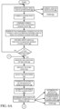
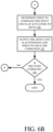
- FIGS. 6A and 6B (collectively referred to herein as FIG. 6 ) show a flow diagram illustrating one example of the operation of agricultural harvester 100 in identifying feed forward spout and flap positions for spout 108 and flap 109, respectively, so that they can be proactively controlled to compensate for the relative change in position of spout 108 relative to receiving vessel 103, while agricultural harvester 100 executes a turn. It is assumed, for the sake of the description of FIG.
- target heading identification system 156 identifies the angle and location of an upcoming turn by analyzing an image obtained from forward-looking device 116, and provides that information to feed forward position compensation control system 220 which generates the feed forward control information identifying positions of vessel 103 and the landing point and provides it to automatic fill control system 160.
- Automatic fill control system 160 in turn, generates control information for controlling spout 108 and flap 109 and outputs the control information to spout position controller 162 and flap position controller 164.
- Spout position controller 162 in turn, generates, control signals to control spout actuator 166, at the proper time, to move spout 108 to compensate for changes in position caused by harvester 100 executing the turn.
- Flap position controller 164 in turn, generates control signals to control flap actuators 168 so that flap 109 is positioned to compensate for the changes in position as well.
- Automatic fill control system 160 thus first monitors the current spout and flap positions, as indicated by block 300 in the flow diagram of FIG. 6 .
- Control system 160 can monitor the current spout and flap positions by receiving a sensor signal from spout position sensor 184 and flap position sensor 186 which are indicative of the current angles or orientations of spout 108 and flap 109, respectively. Receiving the sensor signals from sensors 184 and 186 is indicated by block 302 in the flow diagram of FIG. 6 .
- Control system 160 can identify the current spout and flap positions and the current landing point in other ways as well, as indicated by block 304.
- Control system 160 may also identify the current landing position of the harvested material, by analyzing images captured from automatic fill control sensors 180. Identifying the current landing point is indicated by block 306 in the flow diagram of FIG. 6 .
- Control system 160 compares the current landing point to the desired landing point.
- the desired landing point may be one generated by active fill control system 159 running the active fill control algorithm 198 or by having manual setpoint control system 161 sense a manually input landing setpoint. Comparing the current landing point to the desired landing point is indicated by block 307. Based on the comparison, automatic fill control system 160 generates outputs to spout position controller 162 and flap position controller 164 to maintain the desired landing point, as indicated by block 308.
- Spout position controller 162 and flap position controller 164 then control the spout and flap actuators 166 and 168, respectively, so that the positions of spout 108 and flap 109 are controlled to maintain a desired landing point within the receiving vessel 103. Controlling the spout and flap actuators 166 and 168 in this way is indicated by block 309 in the flow diagram of FIG. 6 .
- the desired landing point may be the current landing point, as set by the operator or by an active fill control algorithm, or in other ways.
- Target heading identification system 156 determines whether a turn is approaching. This can be done by analyzing the information provided by forward-looking device 116, or in other ways. Determining whether a turn is approaching is indicated by block 310 in the flow diagram of FIG. 6 . If no turn is approaching, then processing reverts to block 300 where the system continues to monitor the current spout and flap positions and/or the current landing point, and continues to control the spout 108 and flap 109 to maintain a desired landing point. However, if, at block 310, it is determined that a turn is approaching, then turn angle and location identifier 212 identifies the location of the turn.
- the location of the turn can be identified based upon where the turn begins relative to the location of harvester 100, where the turn begins and ends, the center of the turn, or in other ways. Identifying the location of the turn relative to the location of harvester 100 can be done using the current geographic position of agricultural harvester 100 indicated by the sensor signal from geographic position sensor 188, along with machine dimensions and dynamics of harvester 100 and/or geometric image processing performed on the image output by camera 190, or in other ways. For instance, if it is known where the field of view of camera 190 (and hence area 117) is relative to harvester 100 based on machine dimensions and dynamic or based on geometric image processing, then the location of a turn in area 117, relative to the location of harvester 100, can be determined. Identifying the location of the turn is indicated by block 312 in the flow diagram of FIG. 6 .
- Turn angle and location identifier 212 may also identify the turn angle, as indicated by block 314.
- the turn angle can be identified in a number of different ways. For instance, where harvester 100 is following a windrow, geographic image processing can be performed to identify the windrow, and identify the angle of the turn in the windrow. Similar processing can be performed when harvester 100 is following crop rows. Also, where the edge of the harvested crop is identified (such as where the harvester is cutting alfalfa, sugarcane, or another crop), then the turn angle can be identified by identifying how sharply the edge of the crop turns.
- Feed forward position compensation control system 220 then generates information that can be used to command movement of spout 108 and flap 109, in a feed forward way, to compensate for the relative change in position between spout 108 and the receiving vessel 103 that will occur when harvester 100 executes the upcoming turn.
- Control system 220 can thus obtain the machine speed of harvester 100 from machine speed sensor 194. Detecting machine speed is indicated by block 316 in the flow diagram of FIG. 6 .
- the receiving vehicle position identifier 222 generates an estimate of the position that the receiving vehicle will be in, as agricultural harvester 100 begins, continues through, and exits the upcoming turn. Generating an estimate of the receiving vehicle position is indicated by block 318 in the flow diagram of FIG. 6 .
- Landing point position identifier 224 generates an estimate of the landing point in the receiving vehicle, as harvester 100 executes the turn, as indicated by block 320. Based upon the estimated receiving vehicle position and landing point, the spout and flap positions that are needed to perform a desired fill operation are determined, as indicated by block 322.
- active fill control system 159 may be providing position signals or other signals to spout position controller 162 and flap position controller 164 so that spout 108 and flap 109 are controlled according to an active fill strategy, as indicated by block 324.
- active fill strategy as indicated by block 324.
- the spout and flap position information can be determined in accordance with performing a fill operation in other ways as well, as indicated by block 328.
- Timing identifier 226 identifies a time when the spout actuators 166 and flap actuators 168 should be commanded to move, so that the position of spout 108 can be changed to compensate for the relative change in position between the spout 108 and the receiving vessel 103 caused by harvester 100 executing the upcoming turn. To determine the timing information, timing identifier 226 can consider the distance the turn is from harvester 100, the speed of harvester 100, the responsiveness of actuators 166 and 168 (which may be predefined, sensed or obtained in other ways), and how far actuators 166 and 168 must travel to maintain the desired landing point during the turn. Determining the timing information is indicated by block 330 in the flow diagram of FIG. 6 .
- output generator 230 then outputs the spout and flap positions and the timing information indicating when to issue commands to the spout actuators 166 and flap actuators 168 in order to compensate for the change in relative position between spout 108 and receiving vessel 103 caused by harvester 100 executing the turn. Outputting the spout and flap positions and timing information is indicated by block 332 in the flow diagram of FIG. 6 .
- processing reverts to block 312 where the continued turn location and turn angle are identified, the machine speed is detected, the estimates of receiving vehicle position and landing point are generated, and the desired spout and flap positions, along with the timing information, are also determined.
- the present discussion proceeds with respect to a system that identifies an upcoming turn, before it is reached by harvester 100. Based on the location of the turn, and the turn angle, the present description generates feed forward data that can be used to control the position of spout 108 and flap 109, ahead of time, so that even if there is a significant delay due to the responsiveness of actuators 166 and 168, or for other reasons, the spout 108 and flap 109 can still be positioned quickly enough to compensate for the change in position of spout 108 relative to receiving vessel 103 which is caused by harvester 100 executing the turn. This results in reduced loss of harvested material, even during turns.
- processors and servers include computer processors with associated memory and timing circuitry, not separately shown. They are functional parts of the systems or devices to which they belong and are activated by, and facilitate the functionality of the other components or items in those systems.
- the interface displays can take a wide variety of different forms and can have a wide variety of different user actuatable input mechanisms disposed thereon.
- the user actuatable input mechanisms can be text boxes, check boxes, icons, links, drop-down menus, search boxes, etc.
- the mechanisms can also be actuated in a wide variety of different ways.
- the mechanisms can be actuated using a point and click device (such as a track ball or mouse).
- the mechanisms can be actuated using hardware buttons, switches, a joystick or keyboard, thumb switches or thumb pads, etc.
- the mechanisms can also be actuated using a virtual keyboard or other virtual actuators.
- the screen on which they are displayed is a touch sensitive screen
- the mechanisms can be actuated using touch gestures.
- the device that displays them has speech recognition components, the mechanisms can be actuated using speech commands.
- data stores can each be broken into multiple data stores. All can be local to the systems accessing them, all can be remote, or some can be local while others are remote. All of these configurations are contemplated herein.
- the figures show a number of blocks with functionality ascribed to each block. It will be noted that fewer blocks can be used so the functionality is performed by fewer components. Also, more blocks can be used with the functionality distributed among more components.
- systems, components and/or logic can be comprised of hardware items (such as processors and associated memory, or other processing components, some of which are described below) that perform the functions associated with those systems, components and/or logic.
- the systems, components and/or logic can be comprised of software that is loaded into a memory and is subsequently executed by a processor or server, or other computing component, as described below.
- the systems, components and/or logic can also be comprised of different combinations of hardware, software, firmware, etc., some examples of which are described below.
- FIG. 7 is a block diagram of harvester 100, shown in FIGS. 1-4 , except that it communicates with elements in a remote server architecture 500.
- remote server architecture 500 can provide computation, software, data access, and storage services that do not require end-user knowledge of the physical location or configuration of the system that delivers the services.
- remote servers can deliver the services over a wide area network, such as the internet, using appropriate protocols. For instance, remote servers can deliver applications over a wide area network and they can be accessed through a web browser or any other computing component.
- Software or components shown in FIGS. 1-4 as well as the corresponding data, can be stored on servers at a remote location.
- the computing resources in a remote server environment can be consolidated at a remote data center location or they can be dispersed.
- Remote server infrastructures can deliver services through shared data centers, even though the servers appear as a single point of access for the user.
- the components and functions described herein can be provided from a remote server at a remote location using a remote server architecture.
- the components and functions can be provided from a conventional server, or they can be installed on client devices directly, or in other ways.
- FIG. 7 specifically shows that data store 152, other systems 176, and other parts of the harvester 100 shown in FIG. 4 can be located at a remote server location 502. Therefore, harvester 100 accesses those systems through remote server location 502.
- FIG. 7 also depicts another example of a remote server architecture.
- FIG. 7 shows that it is also contemplated that some elements of FIG. 4 are disposed at remote server location 502 while others are not.
- data store 152 or other systems 176 can be disposed at a location separate from location 502, and accessed through the remote server at location 502.
- the items can be accessed directly by harvester 100, through a network (such as a wide area network or a local area network), the items can be hosted at a remote site by a service, or they can be provided as a service, or accessed by a connection service that resides in a remote location.
- a network such as a wide area network or a local area network
- the data can be stored in substantially any location and intermittently accessed by, or forwarded to, interested parties.
- physical carriers can be used instead of, or in addition to, electromagnetic wave carriers.
- another mobile machine such as a fuel truck
- the system automatically collects the information from the harvester 100 using any type of ad-hoc wireless connection.
- the collected information can then be forwarded to the main network as the fuel truck reaches a location where there is cellular coverage (or other wireless coverage).
- the fuel truck may enter a covered location when traveling to fuel other machines or when at a main fuel storage location. All of these architectures are contemplated herein.
- the information can be stored on the harvester 100 until the harvester 100 enters a covered location.
- the harvester 100 itself, can then send the information to the main network.
- FIGS. 1-4 can be disposed on a wide variety of different devices. Some of those devices include servers, desktop computers, laptop computers, tablet computers, or other mobile devices, such as palm top computers, cell phones, smart phones, multimedia players, personal digital assistants, etc.
Landscapes
- Environmental Sciences (AREA)
- Life Sciences & Earth Sciences (AREA)
- Engineering & Computer Science (AREA)
- Automation & Control Theory (AREA)
- Physics & Mathematics (AREA)
- General Physics & Mathematics (AREA)
- Remote Sensing (AREA)
- Radar, Positioning & Navigation (AREA)
- Aviation & Aerospace Engineering (AREA)
- Mechanical Engineering (AREA)
- Guiding Agricultural Machines (AREA)
- Harvester Elements (AREA)
- Threshing Machine Elements (AREA)
Claims (9)
- Landwirtschaftliches System, das Folgendes umfasst:eine landwirtschaftliche Erntemaschine (100), die einen Rahmen besitzt;ein Abtankrohr (108), das ein Auslassende besitzt und relativ zu dem Rahmen beweglich montiert ist;einen Abtankrohr-Aktor (166), der konfiguriert ist, basierend auf einem Steuersignal für den Abtankrohr-Aktor die Bewegung des Abtankrohrs relativ zu dem Rahmen anzutreiben;Erntefunktionalität, die an dem Rahmen montiert ist und konfiguriert ist, Material von einem Feld aufzunehmen und das Material durch das Auslassende des Abtankrohrs auszugeben, wenn sich die landwirtschaftliche Erntemaschine (100) in einer Fahrtrichtung durch das Feld bewegt;einen Richtungsänderungsidentifizierer (212), der konfiguriert ist, einen Ort einer Richtungsänderung vor der landwirtschaftliche Erntemaschine (100) in der Fahrtrichtung zu identifizieren, und einen Richtungsänderungsort-Indikator, der den Ort der Richtungsänderung anzeigt, zu erzeugen;einen Geschwindigkeitsdetektor (194), der konfiguriert ist, eine Geschwindigkeit der landwirtschaftlichen Erntemaschine zu detektieren und einen Geschwindigkeits-Indikator, der die detektierte Geschwindigkeit anzeigt, erzeugt;ein Positionskompensations-Steuersystem (155), das konfiguriert ist, basierend auf dem Richtungsänderungsort-Indikator und dem Geschwindigkeits-Indikator Abtankrohrpositions-Kompensationsinformationen zum Steuern des Abtankrohr-Aktors zu erzeugen, wobei das Positionskompensations-Steuersystem konfiguriert ist, die Abtankrohrpositions-Kompensationsinformationen zu der Abtankrohrpositions-Steuereinrichtung zu senden, bevor die landwirtschaftliche Erntemaschine die Richtungsänderung ausführt; undeine Abtankrohrpositions-Steuereinrichtung (162), die konfiguriert ist, das Abtankrohr-Aktorsteuersignal zu erzeugen, um den Abtankrohr-Aktor (166) basierend auf den Abtankrohrpositions-Kompensationsinformationen zu steuern;dadurch gekennzeichnet, dass der Richtungsänderungsidentifizierer (212) einen Richtungsänderungswinkel-Identifizierer umfasst, der konfiguriert ist, eine Kennlinie zu identifizieren, die einen Winkel der Richtungsänderung anzeigt, und basierend auf dem Winkel der Richtungsänderung einen Richtungsänderungswinkel-Indikator erzeugt, wobei das Positionskompensations-Steuersystem (155) konfiguriert ist, die Abtankrohrpositions-Kompensationsinformationen zu erzeugen, um den Abtankrohr-Aktor (166) basierend auf dem Richtungsänderungswinkel-Indikator zu steuern.
- Landwirtschaftliches System nach Anspruch 1, das ferner einen vorwärtsgerichteten Sensor (192) umfasst, der konfiguriert ist, ein Bild des Materials vor der landwirtschaftlichen Erntemaschine (100) in der Fahrtrichtung zu erfassen und ein materialcharakteristisches Bildsignal, das das erfasste Bild anzeigt, zu erzeugen.
- Landwirtschaftliches System nach Anspruch 2, wobei der Richtungsänderungsidentifizierer (212) einen Bildprozessor (214) umfasst, der konfiguriert ist, eine Ausrichtung des Materials vor der landwirtschaftlichen Erntemaschine (100) zu identifizieren und den Ort der Richtungsänderung basierend auf der Ausrichtung des Materials zu identifizieren.
- Landwirtschaftliches System nach Anspruch 3, wobei der Richtungsänderungswinkel-Identifizierer konfiguriert ist, den Richtungsänderungswinkel-Indikator basierend auf der Ausrichtung des Materials zu erzeugen.
- Landwirtschaftliches System nach Anspruch 4, wobei das Material eine Schwade umfasst und wobei der Bildprozessor (214) konfiguriert ist, als die Ausrichtung des Materials eine Richtungsänderung in der Schwade vor der landwirtschaftlichen Erntemaschine (100) und einen Winkel der Richtungsänderung zu identifizieren.
- Landwirtschaftliches System nach Anspruch 4, wobei das Material eine Erntereihe oder Erntekante umfasst und wobei der Bildprozessor (214) konfiguriert ist, als die Ausrichtung des Materials eine Richtungsänderung in der Erntereihe oder Erntekante vor der landwirtschaftlichen Erntemaschine (100) und einen Richtungsänderungswinkel zu identifizieren.
- Landwirtschaftliches System nach Anspruch 1, wobei der Richtungsänderungsidentifizierer (212) einen Kartendaten-Prozessor (216) umfasst, der konfiguriert ist, auf eine vorherige Karte des Feldes zuzugreifen und den Ort der Richtungsänderung und den Winkel der Richtungsänderung zu identifizieren.
- Landwirtschaftliches System nach Anspruch 1, das ferner Folgendes umfasst:eine Auslauftülle (109), die an dem Auslassende des Abtankrohrs (108) beweglich montiert ist; undeinen Auslauftüllenaktor (168), der konfiguriert ist, die Bewegung der Auslauftülle (109) relativ zu dem Abtankrohr (108) anzutreiben, wobei das Positionskompensations-Steuersystem (155) konfiguriert ist, die Auslauftüllenpositions-Kompensationsinformationen zum Steuern des Auslauftüllenaktors (168) basierend auf dem Richtungsänderungsort-Indikator, dem Richtungsänderungswinkel-Indikator und dem Geschwindigkeits-Indikator zu erzeugen; undeine Auslauftüllenpositions-Steuereinrichtung (164), die konfiguriert ist, ein Auslauftüllensteuersignal zu erzeugen, um den Auslauftüllenaktor (168) basierend auf den Auslauftüllenpositions-Kompensationsinformationen zu steuern.
- Landwirtschaftliches System nach Anspruch 8, wobei das Abtankrohr (108) konfiguriert ist, das Material an einen Aufnahmebehälter (103) abzugeben, der von der landwirtschaftlichen Erntemaschine (100) getrennt ist, und wobei das Positionskompensations-Steuersystem (155) konfiguriert ist, eine Änderung einer Position des Auslassendes des Abtankrohrs (108) relativ zu einer Position des Aufnahmebehälters (103) zu bestimmen, die daraus resultieren wird, dass die landwirtschaftliche Erntemaschine (100) die Richtungsänderung ausführt, wobei das Positionskompensations-Steuersystem (155) ferner konfiguriert ist, die Abtankrohrpositions-Kompensationsinformationen und die Auslauftüllenpositions-Kompensationsinformationen basierend auf der Änderung einer Position des Auslassendes des Abtankrohrs (108) relativ zu einer Position des Aufnahmebehälters (103) zu erzeugen, die daraus resultieren wird, dass die landwirtschaftliche Erntemaschine (100) die Richtungsänderung ausführt.
Applications Claiming Priority (1)
| Application Number | Priority Date | Filing Date | Title |
|---|---|---|---|
| US17/178,952 US11968927B2 (en) | 2021-02-18 | 2021-02-18 | Harvester with feed forward control of filling mechanisms |
Publications (2)
| Publication Number | Publication Date |
|---|---|
| EP4046474A1 EP4046474A1 (de) | 2022-08-24 |
| EP4046474B1 true EP4046474B1 (de) | 2024-07-31 |
Family
ID=80122250
Family Applications (1)
| Application Number | Title | Priority Date | Filing Date |
|---|---|---|---|
| EP22154037.0A Active EP4046474B1 (de) | 2021-02-18 | 2022-01-28 | Erntemaschine mit vorwärtssteuerung von füllmechanismen |
Country Status (4)
| Country | Link |
|---|---|
| US (2) | US11968927B2 (de) |
| EP (1) | EP4046474B1 (de) |
| AU (1) | AU2022200213A1 (de) |
| BR (1) | BR102021023660A2 (de) |
Families Citing this family (9)
| Publication number | Priority date | Publication date | Assignee | Title |
|---|---|---|---|---|
| US12520759B2 (en) | 2022-01-26 | 2026-01-13 | Deere & Company | Systems and methods for predicting material dynamics |
| US12082531B2 (en) | 2022-01-26 | 2024-09-10 | Deere & Company | Systems and methods for predicting material dynamics |
| US12298767B2 (en) | 2022-04-08 | 2025-05-13 | Deere & Company | Predictive material consumption map and control |
| US12604791B2 (en) | 2022-07-06 | 2026-04-21 | Deere & Company | Machine control based upon estimated operator skill level trend |
| AU2022473991A1 (en) | 2022-08-11 | 2024-11-14 | Deere & Company | Systems and methods for predictive harvesting logistics |
| EP4568467A4 (de) | 2022-08-11 | 2026-05-06 | Deere & Co | Systeme und verfahren für prädiktive erntelogistik |
| DE102023100539A1 (de) | 2023-01-11 | 2024-07-11 | Deere & Company | Anordnung zur selbsttätigen Kontrolle eines Überladevorgangs von einer Erntemaschine auf ein Transportfahrzeug unter Berücksichtigung von Ernteguteigenschaften |
| CN117023198B (zh) * | 2023-08-31 | 2025-10-28 | 神华准格尔能源有限责任公司 | 输料控制系统、输料控制系统的控制方法和控制装置 |
| GB202316587D0 (en) * | 2023-10-30 | 2023-12-13 | Agco Int Gmbh | Harvesting machine monitoring |
Family Cites Families (16)
| Publication number | Priority date | Publication date | Assignee | Title |
|---|---|---|---|---|
| DE2756539C2 (de) | 1977-12-19 | 1982-12-23 | Karl Mengele & Söhne Maschinenfabrik und Eisengießerei GmbH & Co, 8870 Günzburg | Feldhäcksler |
| US4441846A (en) | 1982-02-09 | 1984-04-10 | Deere & Company | Auto spout aimer with delay |
| DE4403893A1 (de) * | 1994-02-08 | 1995-08-10 | Claas Ohg | Vorrichtung zur automatischen Befüllung von Ladebehältern mit einem Gutstrom |
| DE19531662A1 (de) * | 1995-08-29 | 1997-03-06 | Claas Ohg | Vorrichtung zum automatischen Befüllen von Ladebehältern |
| US6943824B2 (en) * | 2002-03-13 | 2005-09-13 | Deere & Company | Image processing spout control system |
| US8407157B2 (en) * | 2003-12-22 | 2013-03-26 | Deere & Company | Locating harvested material within a work area |
| DE102004052298A1 (de) * | 2004-10-06 | 2006-06-08 | Claas Selbstfahrende Erntemaschinen Gmbh | Überladeassistenzsystem |
| DE102007016670A1 (de) * | 2007-04-04 | 2008-10-09 | Claas Selbstfahrende Erntemaschinen Gmbh | Selbstfahrende landwirtschaftliche Erntemaschine mit steuerbarer Überladeeinrichtung |
| DE102008014001A1 (de) | 2008-03-13 | 2009-09-17 | Claas Selbstfahrende Erntemaschinen Gmbh | Landwirtschaftliche Erntemaschine mit einer Überladeeinrichtung |
| US8405721B2 (en) * | 2008-10-21 | 2013-03-26 | Motion Metrics International Corp. | Method, system and apparatus for monitoring loading of a payload into a load carrying container |
| US8606454B2 (en) | 2011-02-18 | 2013-12-10 | Cnh America Llc | System and method for synchronized control of a harvester and transport vehicle |
| WO2012110544A1 (en) | 2011-02-18 | 2012-08-23 | Cnh Belgium N.V. | Harvester spout control system and method |
| DE102011002071A1 (de) * | 2011-04-15 | 2012-10-18 | Claas Selbstfahrende Erntemaschinen Gmbh | System und Verfahren zur Steuerung der Erntegutüberladung |
| BE1021164B1 (nl) | 2013-10-28 | 2016-01-18 | Cnh Industrial Belgium Nv | Ontlaadsystemen |
| DE112015006213A5 (de) * | 2015-02-24 | 2017-11-16 | MSO Meßtechnik und Ortung GmbH | Verfahren zur Messung des Erntegutmassestroms am Feldhäcksler |
| EP3150052B1 (de) | 2015-09-30 | 2018-06-13 | CLAAS E-Systems KGaA mbH & Co KG | Getreideerntemaschine |
-
2021
- 2021-02-18 US US17/178,952 patent/US11968927B2/en active Active
- 2021-11-24 BR BR102021023660-4A patent/BR102021023660A2/pt unknown
-
2022
- 2022-01-14 AU AU2022200213A patent/AU2022200213A1/en active Pending
- 2022-01-28 EP EP22154037.0A patent/EP4046474B1/de active Active
-
2024
- 2024-03-26 US US18/617,194 patent/US12256672B2/en active Active
Also Published As
| Publication number | Publication date |
|---|---|
| US11968927B2 (en) | 2024-04-30 |
| BR102021023660A2 (pt) | 2022-08-30 |
| US12256672B2 (en) | 2025-03-25 |
| EP4046474A1 (de) | 2022-08-24 |
| US20240292785A1 (en) | 2024-09-05 |
| US20220256770A1 (en) | 2022-08-18 |
| AU2022200213A1 (en) | 2022-09-01 |
Similar Documents
| Publication | Publication Date | Title |
|---|---|---|
| EP4046474B1 (de) | Erntemaschine mit vorwärtssteuerung von füllmechanismen | |
| US12439853B2 (en) | Closed loop control of filling mechanisms | |
| EP3973763B1 (de) | Automatische steuerung eines kamerasystems zum entladen einer erntemaschine | |
| EP3903558B1 (de) | Automatische befüllungssteuerung auf basis von visueller identifizierung von getreideaufnehmenden fahrzeugen | |
| EP4113072B1 (de) | Übertragung des füllstands an ein oder mehrere empfangende fahrzeuge | |
| EP3815486B1 (de) | Automatische füllstrategie für getreidewagen unter verwendung einer volumetrischen füllstandsschätzung mit offener schleife | |
| US12004449B2 (en) | Control system for controlling filling mechanisms in communication with a mobile device | |
| EP4169368B1 (de) | System zum dynamischen detektieren von alarmzuständen und optimierungskriterien | |
| EP3906765B1 (de) | Mählader mit automatischer erfassung eines aufnehmenden fahrzeugs | |
| EP4056019B1 (de) | Erntemaschine mit bedienergestützter positionssteuerung des auswurfkrümmers | |
| US20260101851A1 (en) | Vehicle location with dynamic model and unloading control system | |
| US20260053097A1 (en) | Cross member location and avoidance during an unloading operation | |
| US20250280763A1 (en) | Harvesting machine haulage vehicle coordination control | |
| US12317777B2 (en) | Harvester unloading control system | |
| US20240138298A1 (en) | Multi pass unloading operation | |
| US12495734B2 (en) | Three dimensional grid map for cross member location and avoidance during an unloading operation | |
| EP4360433B1 (de) | Erntemaschinenentladesteuerungssystem mit automatisiertem wagenparameterlokalisator |
Legal Events
| Date | Code | Title | Description |
|---|---|---|---|
| PUAI | Public reference made under article 153(3) epc to a published international application that has entered the european phase |
Free format text: ORIGINAL CODE: 0009012 |
|
| STAA | Information on the status of an ep patent application or granted ep patent |
Free format text: STATUS: THE APPLICATION HAS BEEN PUBLISHED |
|
| AK | Designated contracting states |
Kind code of ref document: A1 Designated state(s): AL AT BE BG CH CY CZ DE DK EE ES FI FR GB GR HR HU IE IS IT LI LT LU LV MC MK MT NL NO PL PT RO RS SE SI SK SM TR |
|
| STAA | Information on the status of an ep patent application or granted ep patent |
Free format text: STATUS: REQUEST FOR EXAMINATION WAS MADE |
|
| 17P | Request for examination filed |
Effective date: 20230224 |
|
| RBV | Designated contracting states (corrected) |
Designated state(s): AL AT BE BG CH CY CZ DE DK EE ES FI FR GB GR HR HU IE IS IT LI LT LU LV MC MK MT NL NO PL PT RO RS SE SI SK SM TR |
|
| GRAP | Despatch of communication of intention to grant a patent |
Free format text: ORIGINAL CODE: EPIDOSNIGR1 |
|
| STAA | Information on the status of an ep patent application or granted ep patent |
Free format text: STATUS: GRANT OF PATENT IS INTENDED |
|
| RIC1 | Information provided on ipc code assigned before grant |
Ipc: A01F 12/46 20060101ALI20240219BHEP Ipc: A01D 61/00 20060101ALI20240219BHEP Ipc: A01D 43/08 20060101ALI20240219BHEP Ipc: A01D 43/073 20060101ALI20240219BHEP Ipc: A01D 41/127 20060101AFI20240219BHEP |
|
| INTG | Intention to grant announced |
Effective date: 20240321 |
|
| GRAS | Grant fee paid |
Free format text: ORIGINAL CODE: EPIDOSNIGR3 |
|
| GRAA | (expected) grant |
Free format text: ORIGINAL CODE: 0009210 |
|
| STAA | Information on the status of an ep patent application or granted ep patent |
Free format text: STATUS: THE PATENT HAS BEEN GRANTED |
|
| AK | Designated contracting states |
Kind code of ref document: B1 Designated state(s): AL AT BE BG CH CY CZ DE DK EE ES FI FR GB GR HR HU IE IS IT LI LT LU LV MC MK MT NL NO PL PT RO RS SE SI SK SM TR |
|
| REG | Reference to a national code |
Ref country code: CH Ref legal event code: EP Ref country code: GB Ref legal event code: FG4D |
|
| REG | Reference to a national code |
Ref country code: DE Ref legal event code: R096 Ref document number: 602022004870 Country of ref document: DE |
|
| REG | Reference to a national code |
Ref country code: IE Ref legal event code: FG4D |
|
| REG | Reference to a national code |
Ref country code: LT Ref legal event code: MG9D |
|
| REG | Reference to a national code |
Ref country code: NL Ref legal event code: MP Effective date: 20240731 |
|
| PG25 | Lapsed in a contracting state [announced via postgrant information from national office to epo] |
Ref country code: PT Free format text: LAPSE BECAUSE OF FAILURE TO SUBMIT A TRANSLATION OF THE DESCRIPTION OR TO PAY THE FEE WITHIN THE PRESCRIBED TIME-LIMIT Effective date: 20241202 |
|
| REG | Reference to a national code |
Ref country code: AT Ref legal event code: MK05 Ref document number: 1707531 Country of ref document: AT Kind code of ref document: T Effective date: 20240731 |
|
| PG25 | Lapsed in a contracting state [announced via postgrant information from national office to epo] |
Ref country code: PT Free format text: LAPSE BECAUSE OF FAILURE TO SUBMIT A TRANSLATION OF THE DESCRIPTION OR TO PAY THE FEE WITHIN THE PRESCRIBED TIME-LIMIT Effective date: 20241202 |
|
| PG25 | Lapsed in a contracting state [announced via postgrant information from national office to epo] |
Ref country code: NO Free format text: LAPSE BECAUSE OF FAILURE TO SUBMIT A TRANSLATION OF THE DESCRIPTION OR TO PAY THE FEE WITHIN THE PRESCRIBED TIME-LIMIT Effective date: 20241031 |
|
| PG25 | Lapsed in a contracting state [announced via postgrant information from national office to epo] |
Ref country code: NL Free format text: LAPSE BECAUSE OF FAILURE TO SUBMIT A TRANSLATION OF THE DESCRIPTION OR TO PAY THE FEE WITHIN THE PRESCRIBED TIME-LIMIT Effective date: 20240731 Ref country code: FI Free format text: LAPSE BECAUSE OF FAILURE TO SUBMIT A TRANSLATION OF THE DESCRIPTION OR TO PAY THE FEE WITHIN THE PRESCRIBED TIME-LIMIT Effective date: 20240731 Ref country code: PL Free format text: LAPSE BECAUSE OF FAILURE TO SUBMIT A TRANSLATION OF THE DESCRIPTION OR TO PAY THE FEE WITHIN THE PRESCRIBED TIME-LIMIT Effective date: 20240731 Ref country code: GR Free format text: LAPSE BECAUSE OF FAILURE TO SUBMIT A TRANSLATION OF THE DESCRIPTION OR TO PAY THE FEE WITHIN THE PRESCRIBED TIME-LIMIT Effective date: 20241101 |
|
| PG25 | Lapsed in a contracting state [announced via postgrant information from national office to epo] |
Ref country code: BG Free format text: LAPSE BECAUSE OF FAILURE TO SUBMIT A TRANSLATION OF THE DESCRIPTION OR TO PAY THE FEE WITHIN THE PRESCRIBED TIME-LIMIT Effective date: 20240731 |
|
| PG25 | Lapsed in a contracting state [announced via postgrant information from national office to epo] |
Ref country code: LV Free format text: LAPSE BECAUSE OF FAILURE TO SUBMIT A TRANSLATION OF THE DESCRIPTION OR TO PAY THE FEE WITHIN THE PRESCRIBED TIME-LIMIT Effective date: 20240731 |
|
| PG25 | Lapsed in a contracting state [announced via postgrant information from national office to epo] |
Ref country code: AT Free format text: LAPSE BECAUSE OF FAILURE TO SUBMIT A TRANSLATION OF THE DESCRIPTION OR TO PAY THE FEE WITHIN THE PRESCRIBED TIME-LIMIT Effective date: 20240731 Ref country code: IS Free format text: LAPSE BECAUSE OF FAILURE TO SUBMIT A TRANSLATION OF THE DESCRIPTION OR TO PAY THE FEE WITHIN THE PRESCRIBED TIME-LIMIT Effective date: 20241130 |
|
| PG25 | Lapsed in a contracting state [announced via postgrant information from national office to epo] |
Ref country code: HR Free format text: LAPSE BECAUSE OF FAILURE TO SUBMIT A TRANSLATION OF THE DESCRIPTION OR TO PAY THE FEE WITHIN THE PRESCRIBED TIME-LIMIT Effective date: 20240731 |
|
| PG25 | Lapsed in a contracting state [announced via postgrant information from national office to epo] |
Ref country code: RS Free format text: LAPSE BECAUSE OF FAILURE TO SUBMIT A TRANSLATION OF THE DESCRIPTION OR TO PAY THE FEE WITHIN THE PRESCRIBED TIME-LIMIT Effective date: 20241031 Ref country code: ES Free format text: LAPSE BECAUSE OF FAILURE TO SUBMIT A TRANSLATION OF THE DESCRIPTION OR TO PAY THE FEE WITHIN THE PRESCRIBED TIME-LIMIT Effective date: 20240731 |
|
| PG25 | Lapsed in a contracting state [announced via postgrant information from national office to epo] |
Ref country code: RS Free format text: LAPSE BECAUSE OF FAILURE TO SUBMIT A TRANSLATION OF THE DESCRIPTION OR TO PAY THE FEE WITHIN THE PRESCRIBED TIME-LIMIT Effective date: 20241031 Ref country code: PL Free format text: LAPSE BECAUSE OF FAILURE TO SUBMIT A TRANSLATION OF THE DESCRIPTION OR TO PAY THE FEE WITHIN THE PRESCRIBED TIME-LIMIT Effective date: 20240731 Ref country code: NO Free format text: LAPSE BECAUSE OF FAILURE TO SUBMIT A TRANSLATION OF THE DESCRIPTION OR TO PAY THE FEE WITHIN THE PRESCRIBED TIME-LIMIT Effective date: 20241031 Ref country code: NL Free format text: LAPSE BECAUSE OF FAILURE TO SUBMIT A TRANSLATION OF THE DESCRIPTION OR TO PAY THE FEE WITHIN THE PRESCRIBED TIME-LIMIT Effective date: 20240731 Ref country code: LV Free format text: LAPSE BECAUSE OF FAILURE TO SUBMIT A TRANSLATION OF THE DESCRIPTION OR TO PAY THE FEE WITHIN THE PRESCRIBED TIME-LIMIT Effective date: 20240731 Ref country code: IS Free format text: LAPSE BECAUSE OF FAILURE TO SUBMIT A TRANSLATION OF THE DESCRIPTION OR TO PAY THE FEE WITHIN THE PRESCRIBED TIME-LIMIT Effective date: 20241130 Ref country code: HR Free format text: LAPSE BECAUSE OF FAILURE TO SUBMIT A TRANSLATION OF THE DESCRIPTION OR TO PAY THE FEE WITHIN THE PRESCRIBED TIME-LIMIT Effective date: 20240731 Ref country code: GR Free format text: LAPSE BECAUSE OF FAILURE TO SUBMIT A TRANSLATION OF THE DESCRIPTION OR TO PAY THE FEE WITHIN THE PRESCRIBED TIME-LIMIT Effective date: 20241101 Ref country code: FI Free format text: LAPSE BECAUSE OF FAILURE TO SUBMIT A TRANSLATION OF THE DESCRIPTION OR TO PAY THE FEE WITHIN THE PRESCRIBED TIME-LIMIT Effective date: 20240731 Ref country code: ES Free format text: LAPSE BECAUSE OF FAILURE TO SUBMIT A TRANSLATION OF THE DESCRIPTION OR TO PAY THE FEE WITHIN THE PRESCRIBED TIME-LIMIT Effective date: 20240731 Ref country code: BG Free format text: LAPSE BECAUSE OF FAILURE TO SUBMIT A TRANSLATION OF THE DESCRIPTION OR TO PAY THE FEE WITHIN THE PRESCRIBED TIME-LIMIT Effective date: 20240731 Ref country code: AT Free format text: LAPSE BECAUSE OF FAILURE TO SUBMIT A TRANSLATION OF THE DESCRIPTION OR TO PAY THE FEE WITHIN THE PRESCRIBED TIME-LIMIT Effective date: 20240731 |
|
| PG25 | Lapsed in a contracting state [announced via postgrant information from national office to epo] |
Ref country code: DK Free format text: LAPSE BECAUSE OF FAILURE TO SUBMIT A TRANSLATION OF THE DESCRIPTION OR TO PAY THE FEE WITHIN THE PRESCRIBED TIME-LIMIT Effective date: 20240731 Ref country code: SM Free format text: LAPSE BECAUSE OF FAILURE TO SUBMIT A TRANSLATION OF THE DESCRIPTION OR TO PAY THE FEE WITHIN THE PRESCRIBED TIME-LIMIT Effective date: 20240731 Ref country code: RO Free format text: LAPSE BECAUSE OF FAILURE TO SUBMIT A TRANSLATION OF THE DESCRIPTION OR TO PAY THE FEE WITHIN THE PRESCRIBED TIME-LIMIT Effective date: 20240731 |
|
| PG25 | Lapsed in a contracting state [announced via postgrant information from national office to epo] |
Ref country code: EE Free format text: LAPSE BECAUSE OF FAILURE TO SUBMIT A TRANSLATION OF THE DESCRIPTION OR TO PAY THE FEE WITHIN THE PRESCRIBED TIME-LIMIT Effective date: 20240731 |
|
| PG25 | Lapsed in a contracting state [announced via postgrant information from national office to epo] |
Ref country code: CZ Free format text: LAPSE BECAUSE OF FAILURE TO SUBMIT A TRANSLATION OF THE DESCRIPTION OR TO PAY THE FEE WITHIN THE PRESCRIBED TIME-LIMIT Effective date: 20240731 |
|
| PG25 | Lapsed in a contracting state [announced via postgrant information from national office to epo] |
Ref country code: SK Free format text: LAPSE BECAUSE OF FAILURE TO SUBMIT A TRANSLATION OF THE DESCRIPTION OR TO PAY THE FEE WITHIN THE PRESCRIBED TIME-LIMIT Effective date: 20240731 |
|
| REG | Reference to a national code |
Ref country code: DE Ref legal event code: R097 Ref document number: 602022004870 Country of ref document: DE |
|
| PLBE | No opposition filed within time limit |
Free format text: ORIGINAL CODE: 0009261 |
|
| STAA | Information on the status of an ep patent application or granted ep patent |
Free format text: STATUS: NO OPPOSITION FILED WITHIN TIME LIMIT |
|
| 26N | No opposition filed |
Effective date: 20250501 |
|
| REG | Reference to a national code |
Ref country code: CH Ref legal event code: PL |
|
| PG25 | Lapsed in a contracting state [announced via postgrant information from national office to epo] |
Ref country code: SE Free format text: LAPSE BECAUSE OF FAILURE TO SUBMIT A TRANSLATION OF THE DESCRIPTION OR TO PAY THE FEE WITHIN THE PRESCRIBED TIME-LIMIT Effective date: 20240731 |
|
| PG25 | Lapsed in a contracting state [announced via postgrant information from national office to epo] |
Ref country code: LU Free format text: LAPSE BECAUSE OF NON-PAYMENT OF DUE FEES Effective date: 20250128 Ref country code: MC Free format text: LAPSE BECAUSE OF FAILURE TO SUBMIT A TRANSLATION OF THE DESCRIPTION OR TO PAY THE FEE WITHIN THE PRESCRIBED TIME-LIMIT Effective date: 20240731 |
|
| PG25 | Lapsed in a contracting state [announced via postgrant information from national office to epo] |
Ref country code: CH Free format text: LAPSE BECAUSE OF NON-PAYMENT OF DUE FEES Effective date: 20250131 |
|
| PG25 | Lapsed in a contracting state [announced via postgrant information from national office to epo] |
Ref country code: IE Free format text: LAPSE BECAUSE OF NON-PAYMENT OF DUE FEES Effective date: 20250128 |
|
| PGFP | Annual fee paid to national office [announced via postgrant information from national office to epo] |
Ref country code: DE Payment date: 20251219 Year of fee payment: 5 |
|
| PGFP | Annual fee paid to national office [announced via postgrant information from national office to epo] |
Ref country code: BE Payment date: 20260127 Year of fee payment: 5 Ref country code: IT Payment date: 20260121 Year of fee payment: 5 |
|
| PGFP | Annual fee paid to national office [announced via postgrant information from national office to epo] |
Ref country code: FR Payment date: 20260126 Year of fee payment: 5 |