EP4046513B1 - Capsule pour une cartouche de gaz - Google Patents
Capsule pour une cartouche de gaz Download PDFInfo
- Publication number
- EP4046513B1 EP4046513B1 EP22156568.2A EP22156568A EP4046513B1 EP 4046513 B1 EP4046513 B1 EP 4046513B1 EP 22156568 A EP22156568 A EP 22156568A EP 4046513 B1 EP4046513 B1 EP 4046513B1
- Authority
- EP
- European Patent Office
- Prior art keywords
- container
- gas generator
- channel
- canister
- casing body
- Prior art date
- Legal status (The legal status is an assumption and is not a legal conclusion. Google has not performed a legal analysis and makes no representation as to the accuracy of the status listed.)
- Active
Links
Images


Classifications
-
- A—HUMAN NECESSITIES
- A41—WEARING APPAREL
- A41D—OUTERWEAR; PROTECTIVE GARMENTS; ACCESSORIES
- A41D13/00—Professional, industrial or sporting protective garments, e.g. surgeons' gowns or garments protecting against blows or punches
- A41D13/015—Professional, industrial or sporting protective garments, e.g. surgeons' gowns or garments protecting against blows or punches with shock-absorbing means
- A41D13/018—Professional, industrial or sporting protective garments, e.g. surgeons' gowns or garments protecting against blows or punches with shock-absorbing means inflatable automatically
Definitions
- the present disclosure relates generally to the sector of providing protection by means of an airbag, so as to protect a user from impacts due to falling or sliding, when travelling on a means of transport, such as a vehicle, preferably a two-wheeled vehicle, or any other means of transport, such as a horse or other animal, sports equipment, such as a pair of skis or a bobsleigh, or similar means of transport, or to protect a user when performing any activity also without transport means.
- a means of transport such as a vehicle, preferably a two-wheeled vehicle, or any other means of transport, such as a horse or other animal, sports equipment, such as a pair of skis or a bobsleigh, or similar means of transport, or to protect a user when performing any activity also without transport means.
- the present disclosure relates to a container for a gas generator, for example a container designed to be placed on the back or flank of a user, namely in a zone of a user's body.
- the present disclosure also relates to an inflation device, including the aforementioned container or gas generator for inflating an inflatable element for protecting a user in the event of falls and/or impacts of various types.
- an inflation device including the aforementioned container or gas generator for inflating an inflatable element for protecting a user in the event of falls and/or impacts of various types.
- protection devices including an inflatable element, namely airbag, which are inflated, in the event of an impact, by an inflation device in fluid communication with the airbag itself.
- this inflation device consists of a fluid source, such as a cylindrical compressed-gas canister, which is fixed to the back portion of a protection device or a garment or arranged inside a back protector.
- a fluid source such as a cylindrical compressed-gas canister
- the known inflation devices comprise a support structure which is formed by plates or other rigid mechanical components generally arranged in the region of the user's spinal column.
- This support structure is designed to support the gas generator(s) and is generally connected to a protection garment comprising an inflatable element.
- WO01/54523A1 discloses a container for a cylindrical compressed gas canister.
- the present disclosure is based on a recognition by the inventor of the present disclosure that the inflation devices such as those made available hitherto by the prior art, while being advantageous from many points of view, have not always been sufficient to ensure satisfactory mobility and comfort during use by a user.
- the inflation devices have been hitherto designed and arranged on protective garments so as to prevent them from being dangerous for the user in the event of falls, but without paying too much attention to the question of ensuring the freedom of movement of the user and the comfort during use in general.
- the known inflation devices may not be easily removed from a protection garment by a user. This means that the user may not, autonomously, separate the inflation device from the protective garment in order to perform, for example, washing of the garment or replacement of the compressed-gas canister.
- the starting point of the present disclosure is that of providing a wearable inflation device for an inflatable element, which is able to satisfy all the aforementioned requirements with reference to the prior art and/or achieve further advantages.
- the present disclosure in order to improve the comfort, it is proposed to improve the ergonomic form of the inflation device overall and to make it more suitable for the shape of the body.
- a container which includes a curved casing body.
- the curved casing body may be easily adapted to the curved shape of the body and may be placed so as to fit perfectly against the flank of a user or the user's back.
- the casing body includes a seat or channel having a form suitable for receiving the canister-shaped gas generator.
- the seat may be cylindrical or have another shape suitable for receiving the canister-shaped gas generator.
- the generator in order to adapt the canister-shaped gas generator to the shape of the body, the generator is inserted inside a casing which is curved and more suitable for the anatomy of the human body.
- the casing body is a body made of a soft material which may be removed from the canister-shaped gas generator.
- the casing body is preferably a body able to ensure the cushioning of knocks or impacts.
- the casing body and the canister-shaped gas generator may be handled together as a single body and removed form a personal protection device or a garment with which they are associated, for example for replacement of the gas generator.
- each embodiment of the subject of the present disclosure may have one or more of the advantages listed above; in any case it is not required that each embodiment should have simultaneously all the advantages listed.
- an embodiment of a container for a gas generator is denoted overall by the reference number 1.
- a gas generator is indicated by the reference number 2.
- the canister-shaped gas generator 2 may be a canister containing compressed cold gas, such as helium.
- the canister may be provided with a respective shut-off valve (not shown).
- the inflation fluid source may comprise gas generators preferably of the pyrotechnic or other hybrid type or other types known according to the state of the art.
- the assembly including the gas generator 2 and the container 1 for the gas generator 1 is called an inflation device, denoted generally by the reference number 3.
- the inflation device 3 is connected by means of cables to a control unit (not shown in the drawings) which allows activation of the inflation to be controlled.
- the present disclosure also relates to an inflation device 3 comprising the container 1 and a canister-shaped gas generator 2.
- a further subject of the present disclosure consists of a personal protection device 4 for the personal protection of a user.
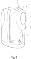
- This personal protection device 4 is a device including, in addition to the inflation device 3, an inflatable element 5 or airbag, in fluid communication with this inflation device 3 and intended to protect at least partly the torso of a user.
- the inflation device 3 is intended to be positioned in a flank region or lumbar region of the user's torso, inside the inflatable element 5, as can be seen in Figure 3 .
- the present disclosure also relates to a wearable article or protective garment, generally indicated by the number 6 in Figure 3 and comprising a personal protection device 4 as defined above.
- the personal protection devices 4 together with the airbags and the protective garments which include said airbags are personal protection devices which are known to the person skilled in the art and therefore are not further described in the present patent application.
- the inflation device 3 is in fluid communication with the inflatable element 5 so as to convey, once activated, inflation fluid into the inflatable element 5 and allow inflation thereof.
- the inflation device 3 is, as mentioned, connected to the control unit by means of which inflation may be activated.
- the protection device 4 is adapted to cooperate with special activation means (normally consisting of the aforementioned control unit and sensors) which are for example operationally connected to the canister-shaped gas generator 2.
- the container 1 for a canister-shaped gas generator 2 comprises a casing body 10 having a curved profile.
- the casing body is curved, namely the casing body has an external surface 101 having a substantially tubular form which defines a curved profile thereof.
- the external surface 101 follows an at least partially curvilinear trajectory.
- the external surface 101 has a progression which is partly arched, curvilinear or curved.
- the external profile of the casing body 10 is especially shaped so as to adapt to the anatomy of a user's torso, in particular the anatomy of a flank region or a lumbar region of a user's torso.
- the casing body 10 therefore follows a curved trajectory, according to a given radius of curvature R.
- the radius of curvature R is chosen so as to correspond to the anatomical curved shape of the flank of a user's body or the lumbar region of a user's back.
- the container 1 may be rested and especially made so as to "fit” or “match” the anatomical curvature of a user's torso.
- the entire casing body is therefore curved.
- the casing body 10 is a hollow body, namely it has a cavity for receiving the gas generator.
- the casing body 10 is provided with a cavity or channel 103 configured to house a conventional canister-shaped gas generator 2.
- the channel 103 therefore has a form and dimensions such as to be able to receive inside it a conventional canister-shaped gas generator 2.
- the known gas generators 2, which are used in the context of personal protection devices generally comprise canisters which have an at least partially cylindrical form. Therefore, the channel 103 acts as a seat for housing a canister-shaped gas generator 2, which preferably has a cylindrical form.
- the channel 103 is formed at least partially inside the casing body 10.
- the channel 102 is an internal cavity of the casing body.
- the casing body 10 surrounds, at least partly, the canister-shaped gas generator 2 and acts as protective covering for the canister-shaped gas generator 2.
- the container 1 is configured so as to protect the canister-shaped gas generator 2 and allow positioning of the latter in a region, such as the flank or the lumbar region, occupying a minimum amount of space and hindering as little as possible the movements of the user, while at the same time housing the canister-shaped gas generator 2.
- the container 1 therefore allows the gas generator to be positioned so as to occupy an anatomical hollow zone of a user's torso.
- the canister-shaped gas generator 2 may be positioned so as to minimize the overall volume presented to the user.
- the casing body 10 has a longitudinal cross-section, along the main direction S, which has a substantially C-shaped form, with a first convex flank or side 10' on one side of the channel 103, and a second concave side or flank 10" on the other side of the channel 103.
- the casing body 10 extends principally along a main direction S parallel to or coinciding with the development axis A of the channel 103.
- the channel 103 is oriented in the main direction S along which the casing body 10 extends.
- the casing body 10 and the channel 103 extend mainly on the same direction. Consequently, the housing body 10 is a substantially tubular body.
- the casing body 10 has, furthermore, an internal surface 102 opposite to the aforementioned external surface 101.
- the internal surface 102 delimits or surrounds the channel 103.
- the channel 103 extends mainly along its own development axis A.
- the channel 103 therefore has a substantially elongated or oblong form, along this development axis A.
- a conventional cannister-shaped gas generator 2 which has an elongated cylindrical form, may be received completely, or at least partly, over most of its length inside the channel 103.
- the internal surface 102 is intended to be completely in contact with a canister-shaped gas generator 2.
- the internal surface 102 rests or lies on the canister-shaped gas generator 2.
- the internal surface 102 adheres to the canister-shaped gas generator 2. In this way no empty spaces, or play, is present between the internal surface 102 and the canister-shaped gas generator 2.
- the casing body 10 is therefore configured to surround tightly the canister-shaped gas generator 2. In this way relative movements of the canister-shaped gas generator 2 with respect to the casing body 10 surrounding it are prevented. Consequently, therefore, during use, the canister-shaped gas generator 2 is firmly retained inside the channel 103.
- the casing body 10 is a single body, i.e. a monolithic body.
- the casing body 10 is made of soft material, such as silicone or other material.
- the container 1 is made of a flexible and/or elastically yielding material.
- the container 1 is made of an elastomeric material; for example, the container 1 may be made of silicone, rubber or latex. In this way, the container 1 is made so as to be particularly flexible and able to cushion both the impacts which could affect the gas generator and the bruising which, in the event of a fall, the inflation device 3 may cause for the user.
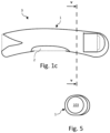
- the soft and flexible material also allows easy unsheathing of the casing body 10, as can be seen in Figure 4 .
- the casing body 10 extends between a first end 103 and a second end 105.
- the first end 104 and the second end 105 are opposite to each other.
- At least one of the first end 104 and the second end 105 has or is provided with an opening 106.
- the opening 106 communicates with the channel 103 so as to allow access to the canister-shaped gas generator 2.
- the through-opening 106 may be in the form of a slot or through-hole.
- the channel 103 is therefore open towards the outside.
- the canister-shaped gas generator 2 may be inserted into or extracted from the channel 103 through the opening 106 during use.
- the canister-shaped gas generator 2 may be connected to the control unit through the opening 106.
- the other end 104 of the casing body 10 is dome or cap-shaped and defines a cavity opening out on one side with the channel 103 and communicating with an environment outside the channel 103.
- the gas output nozzle of the canister-shaped gas generator 2 is directed towards the cavity 111.
- said cavity 111 is configured to direct, orient or steer a gas flow exiting the canister-shaped gas generator 2 towards the airbag 5.
- the casing body 10 may also include a central opening 112 which facilitates unsheathing, as shown in Figure 4 .
Landscapes
- Health & Medical Sciences (AREA)
- General Health & Medical Sciences (AREA)
- Physical Education & Sports Medicine (AREA)
- Engineering & Computer Science (AREA)
- Textile Engineering (AREA)
- Respiratory Apparatuses And Protective Means (AREA)
- Professional, Industrial, Or Sporting Protective Garments (AREA)
- Sampling And Sample Adjustment (AREA)
- Feeding, Discharge, Calcimining, Fusing, And Gas-Generation Devices (AREA)
Claims (14)
- Contenant (1) destiné à un générateur de gaz sous forme de cartouche (2), le contenant (1) comprenant un corps d'enveloppe (10) qui est incurvé ou profilé selon une trajectoire incurvée, et dans lequel le corps d'enveloppe (10) a un canal (103) conçu pour loger le générateur de gaz sous forme de cartouche (2) ; le contenant étant caractérisé en ce que le corps d'enveloppe a un côté externe concave (10") et un côté externe convexe (10').
- Contenant (1) selon la revendication 1, dans lequel ledit canal (103) s'étend principalement le long d'un axe de développement droit ou rectiligne (A).
- Contenant (1) selon la revendication 2, dans lequel, pendant l'utilisation, ledit canal (103) est délimité par une surface interne (102) et ladite surface interne (102) est prévue pour être complètement en contact avec le générateur de gaz sous forme de cartouche (2).
- Contenant (1) selon l'une quelconque des revendications 2 ou 3, dans lequel ledit corps d'enveloppe (10) s'étend le long d'une direction principale (S) parallèle à, ou coïncidant avec, l'axe de développement (A) dudit canal (103).
- Contenant (1) selon l'une quelconque des revendications 2 à 4 précédentes, dans lequel la trajectoire incurvée a un rayon de courbure (R) et ledit rayon de courbure (R) est sensiblement perpendiculaire audit axe de développement (A).
- Contenant (1) selon l'une quelconque des revendications précédentes, dans lequel ledit canal (103) a une forme tubulaire ou cylindrique.
- Contenant (1) selon l'une quelconque des revendications précédentes, dans lequel ledit corps d'enveloppe (10) se développe entre une première extrémité (104) et une seconde extrémité (105), opposée à ladite première extrémité (104), et dans lequel au moins l'une de la première extrémité (104) et de la seconde extrémité (105) est pourvue d'une ouverture (106) communiquant avec ledit canal (103) pour permettre l'insertion et l'extraction du générateur de gaz sous forme de cartouche (2) dans ledit/dudit canal (103) et pour permettre une communication fluidique du générateur de gaz sous forme de cartouche (2) avec un environnement externe audit canal interne (103).
- Contenant (1) selon la revendication 7, dans lequel l'autre extrémité (104) a une cavité (111) communiquant avec ledit canal interne (103) et ouverte en direction d'un environnement externe audit canal (103) et conçu pour diriger un flux de gaz quittant le générateur de gaz sous forme de cartouche (2) en direction dudit environnement externe.
- Contenant (1) selon la revendication 8, dans lequel ladite autre extrémité (104) a une forme hémisphérique ou de demi-dôme.
- Contenant (1) selon l'une quelconque des revendications précédentes, dans lequel le corps d'enveloppe (10) est constitué d'un matériau souple, de préférence un matériau élastomère.
- Dispositif de gonflage (3) comprenant un contenant (1) selon l'une quelconque des revendications précédentes et ledit générateur de gaz sous forme de cartouche (2).
- Dispositif de protection individuelle (4) pour la protection individuelle d'un utilisateur comprenant un dispositif de gonflage (3) selon la revendication 11, un élément gonflable (5) en communication fluidique avec ledit dispositif de gonflage (3) et prévu pour protéger au moins une partie du corps d'un utilisateur.
- Dispositif de protection individuelle (4) selon la revendication 12, dans lequel ledit dispositif de gonflage (3) est prévu pour être positionné dans une région du torse dudit utilisateur.
- Article ou vêtement à porter (6) comprenant un dispositif de protection individuelle (4) selon la revendication 12 ou 13.
Applications Claiming Priority (1)
| Application Number | Priority Date | Filing Date | Title |
|---|---|---|---|
| IT102021000003800A IT202100003800A1 (it) | 2021-02-18 | 2021-02-18 | Contenitore per un generatore di gas |
Publications (3)
| Publication Number | Publication Date |
|---|---|
| EP4046513A1 EP4046513A1 (fr) | 2022-08-24 |
| EP4046513C0 EP4046513C0 (fr) | 2024-01-03 |
| EP4046513B1 true EP4046513B1 (fr) | 2024-01-03 |
Family
ID=75660273
Family Applications (1)
| Application Number | Title | Priority Date | Filing Date |
|---|---|---|---|
| EP22156568.2A Active EP4046513B1 (fr) | 2021-02-18 | 2022-02-14 | Capsule pour une cartouche de gaz |
Country Status (3)
| Country | Link |
|---|---|
| EP (1) | EP4046513B1 (fr) |
| ES (1) | ES2976167T3 (fr) |
| IT (1) | IT202100003800A1 (fr) |
Citations (6)
| Publication number | Priority date | Publication date | Assignee | Title |
|---|---|---|---|---|
| GB546082A (en) | 1942-01-30 | 1942-06-26 | Charles Godfrey Edwards | Improvements in wearing apparel |
| WO1994026136A1 (fr) | 1993-05-14 | 1994-11-24 | Entropy Racing, Inc. | Systeme de protection cervicale |
| WO2005048754A1 (fr) | 2003-11-20 | 2005-06-02 | Alpinestars Research Srl | Vêtement associé à des dispositifs gonflables de protection |
| WO2011148351A1 (fr) | 2010-05-28 | 2011-12-01 | Helite S.A.R.L. | Dispositif pour gonfler un airbag |
| EP3248491A1 (fr) | 2016-05-25 | 2017-11-29 | Helite | Système déployable et équipement comprenant un tel système déployable |
| US10709180B2 (en) | 2016-01-04 | 2020-07-14 | Boe Technology Group Co., Ltd. | Protection system and method |
Family Cites Families (2)
| Publication number | Priority date | Publication date | Assignee | Title |
|---|---|---|---|---|
| JP3070441U (ja) * | 2000-01-21 | 2000-08-04 | 宗平 高島 | 自動ガス膨張式頭部用衝撃緩和装置。 |
| IT201800005175A1 (it) * | 2018-05-08 | 2019-11-08 | Dispositivo di gonfiaggio indossabile |
-
2021
- 2021-02-18 IT IT102021000003800A patent/IT202100003800A1/it unknown
-
2022
- 2022-02-14 ES ES22156568T patent/ES2976167T3/es active Active
- 2022-02-14 EP EP22156568.2A patent/EP4046513B1/fr active Active
Patent Citations (6)
| Publication number | Priority date | Publication date | Assignee | Title |
|---|---|---|---|---|
| GB546082A (en) | 1942-01-30 | 1942-06-26 | Charles Godfrey Edwards | Improvements in wearing apparel |
| WO1994026136A1 (fr) | 1993-05-14 | 1994-11-24 | Entropy Racing, Inc. | Systeme de protection cervicale |
| WO2005048754A1 (fr) | 2003-11-20 | 2005-06-02 | Alpinestars Research Srl | Vêtement associé à des dispositifs gonflables de protection |
| WO2011148351A1 (fr) | 2010-05-28 | 2011-12-01 | Helite S.A.R.L. | Dispositif pour gonfler un airbag |
| US10709180B2 (en) | 2016-01-04 | 2020-07-14 | Boe Technology Group Co., Ltd. | Protection system and method |
| EP3248491A1 (fr) | 2016-05-25 | 2017-11-29 | Helite | Système déployable et équipement comprenant un tel système déployable |
Non-Patent Citations (3)
| Title |
|---|
| ANONYMOUS: "Dainese Launches Smart Jacket", CYCLE NEWS, 19 June 2019 (2019-06-19), pages 1 - 12, XP093232272, Retrieved from the Internet <URL:https://www.cyclenews.com/2019/06/article/dainese-launches-smart-jacket/> |
| D1A - D-AIR SMART JACKET MANUFACTURED BY DAINESE S.P.A. |
| D1D - REGISTRATION EMAIL FOR THE PURCHASING OF THE SMART JACKET |
Also Published As
| Publication number | Publication date |
|---|---|
| EP4046513C0 (fr) | 2024-01-03 |
| IT202100003800A1 (it) | 2022-08-18 |
| ES2976167T3 (es) | 2024-07-24 |
| EP4046513A1 (fr) | 2022-08-24 |
Similar Documents
| Publication | Publication Date | Title |
|---|---|---|
| US5287562A (en) | Helmet to protect cervical spine against axial impact forces | |
| US5390367A (en) | Helmet and shoulder pads having inflatable protective means to protect cervical spine | |
| US5546609A (en) | Helmet | |
| ES2230845T3 (es) | Traje de proteccion. | |
| EP2802228B1 (fr) | Dispositif de protection personnelle et vêtement comprenant un tel dispositif | |
| US11064753B2 (en) | Dual functioning head protection device | |
| EP2994002B1 (fr) | Dispositif de protection individuelle | |
| US4872215A (en) | Chest protector | |
| ES3056389T3 (en) | Wearable protection device | |
| EP4046513B1 (fr) | Capsule pour une cartouche de gaz | |
| US8276217B1 (en) | Personal roll bar | |
| EP0701408A1 (fr) | Procede et dispositif d'enlevement de casque | |
| US7299507B1 (en) | Protective harness for a motorcycle rider | |
| GB2099687A (en) | Inflatable protective garment | |
| EP2745720A1 (fr) | Dispositif de protection | |
| EP4029396B1 (fr) | Dispositif de protection de la tête | |
| WO2011047283A1 (fr) | Système et procédé permettant de retirer un casque équipé d'une coiffe | |
| EP4620338A1 (fr) | Generateur de gaz | |
| IT202100013706A1 (it) | Dispositivo di protezione personale | |
| EP0931567A3 (fr) | Dispositif de sécurité contre les avalanches | |
| CN201291828Y (zh) | 一种安全带安全防护气囊 | |
| EP4327685A1 (fr) | Dispositif de protection portable | |
| JP2017036523A (ja) | 手袋用指先保護具および手袋 | |
| EP4434382B1 (fr) | Dispositif de gonflage | |
| KR20240000664U (ko) | 에어백 기반 재활 보조 장치 |
Legal Events
| Date | Code | Title | Description |
|---|---|---|---|
| PUAI | Public reference made under article 153(3) epc to a published international application that has entered the european phase |
Free format text: ORIGINAL CODE: 0009012 |
|
| STAA | Information on the status of an ep patent application or granted ep patent |
Free format text: STATUS: THE APPLICATION HAS BEEN PUBLISHED |
|
| AK | Designated contracting states |
Kind code of ref document: A1 Designated state(s): AL AT BE BG CH CY CZ DE DK EE ES FI FR GB GR HR HU IE IS IT LI LT LU LV MC MK MT NL NO PL PT RO RS SE SI SK SM TR |
|
| STAA | Information on the status of an ep patent application or granted ep patent |
Free format text: STATUS: REQUEST FOR EXAMINATION WAS MADE |
|
| 17P | Request for examination filed |
Effective date: 20230222 |
|
| RBV | Designated contracting states (corrected) |
Designated state(s): AL AT BE BG CH CY CZ DE DK EE ES FI FR GB GR HR HU IE IS IT LI LT LU LV MC MK MT NL NO PL PT RO RS SE SI SK SM TR |
|
| RIC1 | Information provided on ipc code assigned before grant |
Ipc: A41D 13/018 20060101AFI20230614BHEP |
|
| GRAP | Despatch of communication of intention to grant a patent |
Free format text: ORIGINAL CODE: EPIDOSNIGR1 |
|
| STAA | Information on the status of an ep patent application or granted ep patent |
Free format text: STATUS: GRANT OF PATENT IS INTENDED |
|
| INTG | Intention to grant announced |
Effective date: 20230721 |
|
| GRAS | Grant fee paid |
Free format text: ORIGINAL CODE: EPIDOSNIGR3 |
|
| GRAA | (expected) grant |
Free format text: ORIGINAL CODE: 0009210 |
|
| STAA | Information on the status of an ep patent application or granted ep patent |
Free format text: STATUS: THE PATENT HAS BEEN GRANTED |
|
| AK | Designated contracting states |
Kind code of ref document: B1 Designated state(s): AL AT BE BG CH CY CZ DE DK EE ES FI FR GB GR HR HU IE IS IT LI LT LU LV MC MK MT NL NO PL PT RO RS SE SI SK SM TR |
|
| REG | Reference to a national code |
Ref country code: GB Ref legal event code: FG4D |
|
| REG | Reference to a national code |
Ref country code: CH Ref legal event code: EP |
|
| REG | Reference to a national code |
Ref country code: DE Ref legal event code: R096 Ref document number: 602022001498 Country of ref document: DE |
|
| REG | Reference to a national code |
Ref country code: IE Ref legal event code: FG4D |
|
| U01 | Request for unitary effect filed |
Effective date: 20240131 |
|
| U07 | Unitary effect registered |
Designated state(s): AT BE BG DE DK EE FI FR IT LT LU LV MT NL PT SE SI Effective date: 20240213 |
|
| U20 | Renewal fee for the european patent with unitary effect paid |
Year of fee payment: 3 Effective date: 20240220 |
|
| PG25 | Lapsed in a contracting state [announced via postgrant information from national office to epo] |
Ref country code: IS Free format text: LAPSE BECAUSE OF FAILURE TO SUBMIT A TRANSLATION OF THE DESCRIPTION OR TO PAY THE FEE WITHIN THE PRESCRIBED TIME-LIMIT Effective date: 20240503 |
|
| PG25 | Lapsed in a contracting state [announced via postgrant information from national office to epo] |
Ref country code: GR Free format text: LAPSE BECAUSE OF FAILURE TO SUBMIT A TRANSLATION OF THE DESCRIPTION OR TO PAY THE FEE WITHIN THE PRESCRIBED TIME-LIMIT Effective date: 20240404 |
|
| PG25 | Lapsed in a contracting state [announced via postgrant information from national office to epo] |
Ref country code: HR Free format text: LAPSE BECAUSE OF FAILURE TO SUBMIT A TRANSLATION OF THE DESCRIPTION OR TO PAY THE FEE WITHIN THE PRESCRIBED TIME-LIMIT Effective date: 20240103 Ref country code: RS Free format text: LAPSE BECAUSE OF FAILURE TO SUBMIT A TRANSLATION OF THE DESCRIPTION OR TO PAY THE FEE WITHIN THE PRESCRIBED TIME-LIMIT Effective date: 20240403 |
|
| PG25 | Lapsed in a contracting state [announced via postgrant information from national office to epo] |
Ref country code: CZ Free format text: LAPSE BECAUSE OF FAILURE TO SUBMIT A TRANSLATION OF THE DESCRIPTION OR TO PAY THE FEE WITHIN THE PRESCRIBED TIME-LIMIT Effective date: 20240103 |
|
| REG | Reference to a national code |
Ref country code: ES Ref legal event code: FG2A Ref document number: 2976167 Country of ref document: ES Kind code of ref document: T3 Effective date: 20240724 |
|
| PG25 | Lapsed in a contracting state [announced via postgrant information from national office to epo] |
Ref country code: RS Free format text: LAPSE BECAUSE OF FAILURE TO SUBMIT A TRANSLATION OF THE DESCRIPTION OR TO PAY THE FEE WITHIN THE PRESCRIBED TIME-LIMIT Effective date: 20240403 Ref country code: NO Free format text: LAPSE BECAUSE OF FAILURE TO SUBMIT A TRANSLATION OF THE DESCRIPTION OR TO PAY THE FEE WITHIN THE PRESCRIBED TIME-LIMIT Effective date: 20240403 Ref country code: IS Free format text: LAPSE BECAUSE OF FAILURE TO SUBMIT A TRANSLATION OF THE DESCRIPTION OR TO PAY THE FEE WITHIN THE PRESCRIBED TIME-LIMIT Effective date: 20240503 Ref country code: HR Free format text: LAPSE BECAUSE OF FAILURE TO SUBMIT A TRANSLATION OF THE DESCRIPTION OR TO PAY THE FEE WITHIN THE PRESCRIBED TIME-LIMIT Effective date: 20240103 Ref country code: GR Free format text: LAPSE BECAUSE OF FAILURE TO SUBMIT A TRANSLATION OF THE DESCRIPTION OR TO PAY THE FEE WITHIN THE PRESCRIBED TIME-LIMIT Effective date: 20240404 Ref country code: CZ Free format text: LAPSE BECAUSE OF FAILURE TO SUBMIT A TRANSLATION OF THE DESCRIPTION OR TO PAY THE FEE WITHIN THE PRESCRIBED TIME-LIMIT Effective date: 20240103 |
|
| PG25 | Lapsed in a contracting state [announced via postgrant information from national office to epo] |
Ref country code: PL Free format text: LAPSE BECAUSE OF FAILURE TO SUBMIT A TRANSLATION OF THE DESCRIPTION OR TO PAY THE FEE WITHIN THE PRESCRIBED TIME-LIMIT Effective date: 20240103 |
|
| PG25 | Lapsed in a contracting state [announced via postgrant information from national office to epo] |
Ref country code: PL Free format text: LAPSE BECAUSE OF FAILURE TO SUBMIT A TRANSLATION OF THE DESCRIPTION OR TO PAY THE FEE WITHIN THE PRESCRIBED TIME-LIMIT Effective date: 20240103 |
|
| REG | Reference to a national code |
Ref country code: DE Ref legal event code: R026 Ref document number: 602022001498 Country of ref document: DE |
|
| PLBI | Opposition filed |
Free format text: ORIGINAL CODE: 0009260 |
|
| PG25 | Lapsed in a contracting state [announced via postgrant information from national office to epo] |
Ref country code: SM Free format text: LAPSE BECAUSE OF FAILURE TO SUBMIT A TRANSLATION OF THE DESCRIPTION OR TO PAY THE FEE WITHIN THE PRESCRIBED TIME-LIMIT Effective date: 20240103 |
|
| PLAX | Notice of opposition and request to file observation + time limit sent |
Free format text: ORIGINAL CODE: EPIDOSNOBS2 |
|
| PG25 | Lapsed in a contracting state [announced via postgrant information from national office to epo] |
Ref country code: SK Free format text: LAPSE BECAUSE OF FAILURE TO SUBMIT A TRANSLATION OF THE DESCRIPTION OR TO PAY THE FEE WITHIN THE PRESCRIBED TIME-LIMIT Effective date: 20240103 |
|
| PG25 | Lapsed in a contracting state [announced via postgrant information from national office to epo] |
Ref country code: SM Free format text: LAPSE BECAUSE OF FAILURE TO SUBMIT A TRANSLATION OF THE DESCRIPTION OR TO PAY THE FEE WITHIN THE PRESCRIBED TIME-LIMIT Effective date: 20240103 Ref country code: SK Free format text: LAPSE BECAUSE OF FAILURE TO SUBMIT A TRANSLATION OF THE DESCRIPTION OR TO PAY THE FEE WITHIN THE PRESCRIBED TIME-LIMIT Effective date: 20240103 Ref country code: RO Free format text: LAPSE BECAUSE OF FAILURE TO SUBMIT A TRANSLATION OF THE DESCRIPTION OR TO PAY THE FEE WITHIN THE PRESCRIBED TIME-LIMIT Effective date: 20240103 |
|
| PG25 | Lapsed in a contracting state [announced via postgrant information from national office to epo] |
Ref country code: MC Free format text: LAPSE BECAUSE OF FAILURE TO SUBMIT A TRANSLATION OF THE DESCRIPTION OR TO PAY THE FEE WITHIN THE PRESCRIBED TIME-LIMIT Effective date: 20240103 |
|
| 26 | Opposition filed |
Opponent name: ALPINESTARS S.P.A. Effective date: 20241004 |
|
| PG25 | Lapsed in a contracting state [announced via postgrant information from national office to epo] |
Ref country code: MC Free format text: LAPSE BECAUSE OF FAILURE TO SUBMIT A TRANSLATION OF THE DESCRIPTION OR TO PAY THE FEE WITHIN THE PRESCRIBED TIME-LIMIT Effective date: 20240103 |
|
| PG25 | Lapsed in a contracting state [announced via postgrant information from national office to epo] |
Ref country code: IE Free format text: LAPSE BECAUSE OF NON-PAYMENT OF DUE FEES Effective date: 20240214 |
|
| PG25 | Lapsed in a contracting state [announced via postgrant information from national office to epo] |
Ref country code: IE Free format text: LAPSE BECAUSE OF NON-PAYMENT OF DUE FEES Effective date: 20240214 |
|
| PLBB | Reply of patent proprietor to notice(s) of opposition received |
Free format text: ORIGINAL CODE: EPIDOSNOBS3 |
|
| U20 | Renewal fee for the european patent with unitary effect paid |
Year of fee payment: 4 Effective date: 20250224 |
|
| PGFP | Annual fee paid to national office [announced via postgrant information from national office to epo] |
Ref country code: ES Payment date: 20250331 Year of fee payment: 4 |
|
| PG25 | Lapsed in a contracting state [announced via postgrant information from national office to epo] |
Ref country code: CY Free format text: LAPSE BECAUSE OF FAILURE TO SUBMIT A TRANSLATION OF THE DESCRIPTION OR TO PAY THE FEE WITHIN THE PRESCRIBED TIME-LIMIT; INVALID AB INITIO Effective date: 20220214 |
|
| REG | Reference to a national code |
Ref country code: CH Ref legal event code: PL |
|
| PG25 | Lapsed in a contracting state [announced via postgrant information from national office to epo] |
Ref country code: CH Free format text: LAPSE BECAUSE OF NON-PAYMENT OF DUE FEES Effective date: 20250228 |
|
| PG25 | Lapsed in a contracting state [announced via postgrant information from national office to epo] |
Ref country code: TR Free format text: LAPSE BECAUSE OF FAILURE TO SUBMIT A TRANSLATION OF THE DESCRIPTION OR TO PAY THE FEE WITHIN THE PRESCRIBED TIME-LIMIT Effective date: 20240103 |
|
| U1N | Appointed representative for the unitary patent procedure changed after the registration of the unitary effect |
Representative=s name: DE SANDRE, EMANUELE; IT |
|
| U20 | Renewal fee for the european patent with unitary effect paid |
Year of fee payment: 5 Effective date: 20260129 |
|
| PGFP | Annual fee paid to national office [announced via postgrant information from national office to epo] |
Ref country code: GB Payment date: 20260220 Year of fee payment: 5 |