EP4046603A1 - Dispositifs et systèmes permettant d'ancrer une valvule cardiaque - Google Patents
Dispositifs et systèmes permettant d'ancrer une valvule cardiaque Download PDFInfo
- Publication number
- EP4046603A1 EP4046603A1 EP21211194.2A EP21211194A EP4046603A1 EP 4046603 A1 EP4046603 A1 EP 4046603A1 EP 21211194 A EP21211194 A EP 21211194A EP 4046603 A1 EP4046603 A1 EP 4046603A1
- Authority
- EP
- European Patent Office
- Prior art keywords
- docking station
- valve
- valve seat
- frame
- expandable
- Prior art date
- Legal status (The legal status is an assumption and is not a legal conclusion. Google has not performed a legal analysis and makes no representation as to the accuracy of the status listed.)
- Pending
Links
Images





























Classifications
-
- A—HUMAN NECESSITIES
- A61—MEDICAL OR VETERINARY SCIENCE; HYGIENE
- A61F—FILTERS IMPLANTABLE INTO BLOOD VESSELS; PROSTHESES; DEVICES PROVIDING PATENCY TO, OR PREVENTING COLLAPSING OF, TUBULAR STRUCTURES OF THE BODY, e.g. STENTS; ORTHOPAEDIC, NURSING OR CONTRACEPTIVE DEVICES; FOMENTATION; TREATMENT OR PROTECTION OF EYES OR EARS; BANDAGES, DRESSINGS OR ABSORBENT PADS; FIRST-AID KITS
- A61F2/00—Filters implantable into blood vessels; Prostheses, i.e. artificial substitutes or replacements for parts of the body; Appliances for connecting them with the body; Devices providing patency to, or preventing collapsing of, tubular structures of the body, e.g. stents
- A61F2/02—Prostheses implantable into the body
- A61F2/24—Heart valves ; Vascular valves, e.g. venous valves; Heart implants, e.g. passive devices for improving the function of the native valve or the heart muscle; Transmyocardial revascularisation [TMR] devices; Valves implantable in the body
- A61F2/2409—Support rings therefor, e.g. for connecting valves to tissue
-
- A—HUMAN NECESSITIES
- A61—MEDICAL OR VETERINARY SCIENCE; HYGIENE
- A61F—FILTERS IMPLANTABLE INTO BLOOD VESSELS; PROSTHESES; DEVICES PROVIDING PATENCY TO, OR PREVENTING COLLAPSING OF, TUBULAR STRUCTURES OF THE BODY, e.g. STENTS; ORTHOPAEDIC, NURSING OR CONTRACEPTIVE DEVICES; FOMENTATION; TREATMENT OR PROTECTION OF EYES OR EARS; BANDAGES, DRESSINGS OR ABSORBENT PADS; FIRST-AID KITS
- A61F2/00—Filters implantable into blood vessels; Prostheses, i.e. artificial substitutes or replacements for parts of the body; Appliances for connecting them with the body; Devices providing patency to, or preventing collapsing of, tubular structures of the body, e.g. stents
- A61F2/02—Prostheses implantable into the body
- A61F2/24—Heart valves ; Vascular valves, e.g. venous valves; Heart implants, e.g. passive devices for improving the function of the native valve or the heart muscle; Transmyocardial revascularisation [TMR] devices; Valves implantable in the body
-
- A—HUMAN NECESSITIES
- A61—MEDICAL OR VETERINARY SCIENCE; HYGIENE
- A61F—FILTERS IMPLANTABLE INTO BLOOD VESSELS; PROSTHESES; DEVICES PROVIDING PATENCY TO, OR PREVENTING COLLAPSING OF, TUBULAR STRUCTURES OF THE BODY, e.g. STENTS; ORTHOPAEDIC, NURSING OR CONTRACEPTIVE DEVICES; FOMENTATION; TREATMENT OR PROTECTION OF EYES OR EARS; BANDAGES, DRESSINGS OR ABSORBENT PADS; FIRST-AID KITS
- A61F2/00—Filters implantable into blood vessels; Prostheses, i.e. artificial substitutes or replacements for parts of the body; Appliances for connecting them with the body; Devices providing patency to, or preventing collapsing of, tubular structures of the body, e.g. stents
- A61F2/02—Prostheses implantable into the body
- A61F2/24—Heart valves ; Vascular valves, e.g. venous valves; Heart implants, e.g. passive devices for improving the function of the native valve or the heart muscle; Transmyocardial revascularisation [TMR] devices; Valves implantable in the body
- A61F2/2412—Heart valves ; Vascular valves, e.g. venous valves; Heart implants, e.g. passive devices for improving the function of the native valve or the heart muscle; Transmyocardial revascularisation [TMR] devices; Valves implantable in the body with soft flexible valve members, e.g. tissue valves shaped like natural valves
- A61F2/2418—Scaffolds therefor, e.g. support stents
-
- A—HUMAN NECESSITIES
- A61—MEDICAL OR VETERINARY SCIENCE; HYGIENE
- A61F—FILTERS IMPLANTABLE INTO BLOOD VESSELS; PROSTHESES; DEVICES PROVIDING PATENCY TO, OR PREVENTING COLLAPSING OF, TUBULAR STRUCTURES OF THE BODY, e.g. STENTS; ORTHOPAEDIC, NURSING OR CONTRACEPTIVE DEVICES; FOMENTATION; TREATMENT OR PROTECTION OF EYES OR EARS; BANDAGES, DRESSINGS OR ABSORBENT PADS; FIRST-AID KITS
- A61F2/00—Filters implantable into blood vessels; Prostheses, i.e. artificial substitutes or replacements for parts of the body; Appliances for connecting them with the body; Devices providing patency to, or preventing collapsing of, tubular structures of the body, e.g. stents
- A61F2/02—Prostheses implantable into the body
- A61F2/24—Heart valves ; Vascular valves, e.g. venous valves; Heart implants, e.g. passive devices for improving the function of the native valve or the heart muscle; Transmyocardial revascularisation [TMR] devices; Valves implantable in the body
- A61F2/2427—Devices for manipulating or deploying heart valves during implantation
-
- A—HUMAN NECESSITIES
- A61—MEDICAL OR VETERINARY SCIENCE; HYGIENE
- A61F—FILTERS IMPLANTABLE INTO BLOOD VESSELS; PROSTHESES; DEVICES PROVIDING PATENCY TO, OR PREVENTING COLLAPSING OF, TUBULAR STRUCTURES OF THE BODY, e.g. STENTS; ORTHOPAEDIC, NURSING OR CONTRACEPTIVE DEVICES; FOMENTATION; TREATMENT OR PROTECTION OF EYES OR EARS; BANDAGES, DRESSINGS OR ABSORBENT PADS; FIRST-AID KITS
- A61F2/00—Filters implantable into blood vessels; Prostheses, i.e. artificial substitutes or replacements for parts of the body; Appliances for connecting them with the body; Devices providing patency to, or preventing collapsing of, tubular structures of the body, e.g. stents
- A61F2/02—Prostheses implantable into the body
- A61F2/24—Heart valves ; Vascular valves, e.g. venous valves; Heart implants, e.g. passive devices for improving the function of the native valve or the heart muscle; Transmyocardial revascularisation [TMR] devices; Valves implantable in the body
- A61F2/2427—Devices for manipulating or deploying heart valves during implantation
- A61F2/2436—Deployment by retracting a sheath
-
- A—HUMAN NECESSITIES
- A61—MEDICAL OR VETERINARY SCIENCE; HYGIENE
- A61F—FILTERS IMPLANTABLE INTO BLOOD VESSELS; PROSTHESES; DEVICES PROVIDING PATENCY TO, OR PREVENTING COLLAPSING OF, TUBULAR STRUCTURES OF THE BODY, e.g. STENTS; ORTHOPAEDIC, NURSING OR CONTRACEPTIVE DEVICES; FOMENTATION; TREATMENT OR PROTECTION OF EYES OR EARS; BANDAGES, DRESSINGS OR ABSORBENT PADS; FIRST-AID KITS
- A61F2/00—Filters implantable into blood vessels; Prostheses, i.e. artificial substitutes or replacements for parts of the body; Appliances for connecting them with the body; Devices providing patency to, or preventing collapsing of, tubular structures of the body, e.g. stents
- A61F2/02—Prostheses implantable into the body
- A61F2/24—Heart valves ; Vascular valves, e.g. venous valves; Heart implants, e.g. passive devices for improving the function of the native valve or the heart muscle; Transmyocardial revascularisation [TMR] devices; Valves implantable in the body
- A61F2/2442—Annuloplasty rings or inserts for correcting the valve shape; Implants for improving the function of a native heart valve
-
- A—HUMAN NECESSITIES
- A61—MEDICAL OR VETERINARY SCIENCE; HYGIENE
- A61F—FILTERS IMPLANTABLE INTO BLOOD VESSELS; PROSTHESES; DEVICES PROVIDING PATENCY TO, OR PREVENTING COLLAPSING OF, TUBULAR STRUCTURES OF THE BODY, e.g. STENTS; ORTHOPAEDIC, NURSING OR CONTRACEPTIVE DEVICES; FOMENTATION; TREATMENT OR PROTECTION OF EYES OR EARS; BANDAGES, DRESSINGS OR ABSORBENT PADS; FIRST-AID KITS
- A61F2/00—Filters implantable into blood vessels; Prostheses, i.e. artificial substitutes or replacements for parts of the body; Appliances for connecting them with the body; Devices providing patency to, or preventing collapsing of, tubular structures of the body, e.g. stents
- A61F2/02—Prostheses implantable into the body
- A61F2/24—Heart valves ; Vascular valves, e.g. venous valves; Heart implants, e.g. passive devices for improving the function of the native valve or the heart muscle; Transmyocardial revascularisation [TMR] devices; Valves implantable in the body
- A61F2/2442—Annuloplasty rings or inserts for correcting the valve shape; Implants for improving the function of a native heart valve
- A61F2/2466—Delivery devices therefor
-
- A—HUMAN NECESSITIES
- A61—MEDICAL OR VETERINARY SCIENCE; HYGIENE
- A61F—FILTERS IMPLANTABLE INTO BLOOD VESSELS; PROSTHESES; DEVICES PROVIDING PATENCY TO, OR PREVENTING COLLAPSING OF, TUBULAR STRUCTURES OF THE BODY, e.g. STENTS; ORTHOPAEDIC, NURSING OR CONTRACEPTIVE DEVICES; FOMENTATION; TREATMENT OR PROTECTION OF EYES OR EARS; BANDAGES, DRESSINGS OR ABSORBENT PADS; FIRST-AID KITS
- A61F2/00—Filters implantable into blood vessels; Prostheses, i.e. artificial substitutes or replacements for parts of the body; Appliances for connecting them with the body; Devices providing patency to, or preventing collapsing of, tubular structures of the body, e.g. stents
- A61F2/02—Prostheses implantable into the body
- A61F2/24—Heart valves ; Vascular valves, e.g. venous valves; Heart implants, e.g. passive devices for improving the function of the native valve or the heart muscle; Transmyocardial revascularisation [TMR] devices; Valves implantable in the body
- A61F2/2475—Venous valves
-
- A—HUMAN NECESSITIES
- A61—MEDICAL OR VETERINARY SCIENCE; HYGIENE
- A61F—FILTERS IMPLANTABLE INTO BLOOD VESSELS; PROSTHESES; DEVICES PROVIDING PATENCY TO, OR PREVENTING COLLAPSING OF, TUBULAR STRUCTURES OF THE BODY, e.g. STENTS; ORTHOPAEDIC, NURSING OR CONTRACEPTIVE DEVICES; FOMENTATION; TREATMENT OR PROTECTION OF EYES OR EARS; BANDAGES, DRESSINGS OR ABSORBENT PADS; FIRST-AID KITS
- A61F2/00—Filters implantable into blood vessels; Prostheses, i.e. artificial substitutes or replacements for parts of the body; Appliances for connecting them with the body; Devices providing patency to, or preventing collapsing of, tubular structures of the body, e.g. stents
- A61F2/95—Instruments specially adapted for placement or removal of stents or stent-grafts
- A61F2/9517—Instruments specially adapted for placement or removal of stents or stent-grafts handle assemblies therefor
-
- A—HUMAN NECESSITIES
- A61—MEDICAL OR VETERINARY SCIENCE; HYGIENE
- A61F—FILTERS IMPLANTABLE INTO BLOOD VESSELS; PROSTHESES; DEVICES PROVIDING PATENCY TO, OR PREVENTING COLLAPSING OF, TUBULAR STRUCTURES OF THE BODY, e.g. STENTS; ORTHOPAEDIC, NURSING OR CONTRACEPTIVE DEVICES; FOMENTATION; TREATMENT OR PROTECTION OF EYES OR EARS; BANDAGES, DRESSINGS OR ABSORBENT PADS; FIRST-AID KITS
- A61F2220/00—Fixations or connections for prostheses classified in groups A61F2/00 - A61F2/26 or A61F2/82 or A61F9/00 or A61F11/00 or subgroups thereof
- A61F2220/0008—Fixation appliances for connecting prostheses to the body
-
- A—HUMAN NECESSITIES
- A61—MEDICAL OR VETERINARY SCIENCE; HYGIENE
- A61F—FILTERS IMPLANTABLE INTO BLOOD VESSELS; PROSTHESES; DEVICES PROVIDING PATENCY TO, OR PREVENTING COLLAPSING OF, TUBULAR STRUCTURES OF THE BODY, e.g. STENTS; ORTHOPAEDIC, NURSING OR CONTRACEPTIVE DEVICES; FOMENTATION; TREATMENT OR PROTECTION OF EYES OR EARS; BANDAGES, DRESSINGS OR ABSORBENT PADS; FIRST-AID KITS
- A61F2220/00—Fixations or connections for prostheses classified in groups A61F2/00 - A61F2/26 or A61F2/82 or A61F9/00 or A61F11/00 or subgroups thereof
- A61F2220/0025—Connections or couplings between prosthetic parts, e.g. between modular parts; Connecting elements
- A61F2220/0075—Connections or couplings between prosthetic parts, e.g. between modular parts; Connecting elements sutured, ligatured or stitched, retained or tied with a rope, string, thread, wire or cable
-
- A—HUMAN NECESSITIES
- A61—MEDICAL OR VETERINARY SCIENCE; HYGIENE
- A61F—FILTERS IMPLANTABLE INTO BLOOD VESSELS; PROSTHESES; DEVICES PROVIDING PATENCY TO, OR PREVENTING COLLAPSING OF, TUBULAR STRUCTURES OF THE BODY, e.g. STENTS; ORTHOPAEDIC, NURSING OR CONTRACEPTIVE DEVICES; FOMENTATION; TREATMENT OR PROTECTION OF EYES OR EARS; BANDAGES, DRESSINGS OR ABSORBENT PADS; FIRST-AID KITS
- A61F2250/00—Special features of prostheses classified in groups A61F2/00 - A61F2/26 or A61F2/82 or A61F9/00 or A61F11/00 or subgroups thereof
- A61F2250/0058—Additional features; Implant or prostheses properties not otherwise provided for
- A61F2250/006—Additional features; Implant or prostheses properties not otherwise provided for modular
-
- A—HUMAN NECESSITIES
- A61—MEDICAL OR VETERINARY SCIENCE; HYGIENE
- A61F—FILTERS IMPLANTABLE INTO BLOOD VESSELS; PROSTHESES; DEVICES PROVIDING PATENCY TO, OR PREVENTING COLLAPSING OF, TUBULAR STRUCTURES OF THE BODY, e.g. STENTS; ORTHOPAEDIC, NURSING OR CONTRACEPTIVE DEVICES; FOMENTATION; TREATMENT OR PROTECTION OF EYES OR EARS; BANDAGES, DRESSINGS OR ABSORBENT PADS; FIRST-AID KITS
- A61F2250/00—Special features of prostheses classified in groups A61F2/00 - A61F2/26 or A61F2/82 or A61F9/00 or A61F11/00 or subgroups thereof
- A61F2250/0058—Additional features; Implant or prostheses properties not otherwise provided for
- A61F2250/0069—Sealing means
Definitions
- the present invention relates to heart valves and, in particular, docking stations/stents, delivery systems, and methods for use in implanting a heart valve, e.g., a transcatheter heart valve ("THV").
- a heart valve e.g., a transcatheter heart valve ("THV").
- TSV transcatheter heart valve
- Prosthetic heart valves can be used to treat cardiac valvular disorders.
- the native heart valves (the aortic, pulmonary, tricuspid and mitral valves) serve critical functions in assuring the forward flow of an adequate supply of blood through the cardiovascular system.
- These heart valves can be rendered less effective by congenital, inflammatory, or infectious conditions. Such conditions can eventually lead to serious cardiovascular compromise or death.
- the definitive treatment for such disorders was the surgical repair or replacement of the valve during open heart surgery.
- a transcatheter technique can also be used for introducing and implanting a prosthetic heart valve using a flexible catheter in a manner that is less invasive than open heart surgery.
- a prosthetic valve can be mounted in a crimped state on the end portion of a flexible catheter and advanced through a blood vessel of the patient until the valve reaches the implantation site.
- the valve at the catheter tip can then be expanded to its functional size at the site of the defective native valve, such as by inflating a balloon on which the valve is mounted.
- the valve can have a resilient, self-expanding stent or frame that expands the valve to its functional size when it is advanced from a delivery sheath at the distal end of the catheter.
- Transcatheter heart valves may be appropriately sized to be placed inside most native aortic valves.
- aortic transcatheter valves might be too small to secure into the larger implantation or deployment site.
- the transcatheter valve may not be large enough to sufficiently expand inside the native valve or other implantation or deployment site to be secured in place.
- Replacing the pulmonary valve which is sometimes referred to as the pulmonic valve, presents significant challenges.
- the geometry of the pulmonary artery can vary greatly from patient to patient.
- the pulmonary artery outflow tract after corrective surgery is too wide for effective placement of a prosthetic heart valve.
- a docking station can include a valve seat, one or more sealing portions, and one or more retaining portions.
- the valve seat can be substantially unexpandable beyond a deployed size, i.e., the diameter of the valve seat may only be able to increase a maximum of 0-4 mm.
- the one or more sealing portions can be connected to the valve seat and extend radially outward of the valve seat.
- the one or more sealing portions can be constructed to expand and extend outward of the valve seat and provide a seal over a range of sizes (e.g., over a range of sizes of expansion and/or over a range of sizes within the circulatory system or vasculature, for example, it may be able to provide a seal when expanding in different blood vessels or locations of a variety of shapes and sizes).
- the one or more retaining portions can be connected to the one or more sealing portions.
- the one or more retaining portions can be configured to retain the docking station at a deployed position.
- the expandable docking station can expand and provide a seal over a range from 27mm to 38mm.
- the expandable docking station can expand radially outwardly to varying degrees along its length L.
- the valve seat and the one or more sealing portions can act as an isolator that reduces or prevents radial outward forces of an expandable valve in the valve seat from being transferred to the one or more sealing portions or the one or more retaining portions.
- the docking station can be configured such that pressure of blood enhances the retention by the retaining portions.
- the one or more retaining portions can be configured such that force applied by at least one of the one or more retaining portions at the deployed position is in proportion to the pressure of blood acting on the docking station.
- the one or more retaining portions can be configured such that force applied by at least one of the one or more retaining portions is greater when the heart is in a diastolic phase than when the heart is in the systolic phase.
- the valve seat can be formed by a suture, ring, band, structural arrangement, material, foam, and in other ways.
- the sealing portion can comprise a portion of a metal frame covered with a fabric, polymer, and/or other material.
- the sealing portion can comprise an open cell foam.
- a portion of the docking station can be permeable to blood and a portion of the docking station can be impermeable to blood.
- a portion of the docking station that is impermeable to blood can extend from at least the valve seat to at least the sealing portion.
- the docking station can be adjustable in length.
- the docking station can include a first half that a second half of the docking station can adjustably extend into to adjust the length.
- the one or more retaining portions can extend radially outward of the one or more sealing portions when the docking station is in an unconstrained state. Other features described elsewhere in this disclosure may also be included.
- a system can include an expandable docking station and an expandable valve.
- the expandable docking station can include a valve seat, one or more sealing portions, and one or more retaining portions.
- the valve seat can expand to a deployed size.
- the one or more sealing portions can be connected to the valve seat and can be constructed to expand and extend radially outward of the valve seat and provide a seal over a range of sizes of expansion.
- the one or more retaining portions can be connected to the one or more sealing portions.
- the one or more retaining portions can be configured to retain the docking station at a deployed position.
- the expandable valve can include an expandable frame and a valve element. The expandable frame can be expanded to engage the valve seat of the docking station.
- the valve element can be connected to the expandable frame.
- the expandable docking station and expandable valve can be configured such that, when implanted in a portion of a circulatory system, a radial outward force applied by the sealing portions to the portion of the circulatory system, when sealing portions are within the range of sizes, is less than 1 ⁇ 2 (and can be less than 1/3, less than 1/4, less than 1/8, or less than 1/10) of a radial outward force applied by the expandable frame to the valve seat.
- the expandable docking station can be configured such that, when implanted in the portion of the circulatory system, the diameter of the valve seat is not increased more than 3mm (or not more than 1mm, 2mm, or 4mm) by the radial outward force applied by the expandable frame to the valve seat.
- the range of sizes of the sealing portions can be from 27mm to 38mm.
- the expandable docking station can be configured to expand radially outwardly to varying degrees along its length L when implanted in the portion of the circulatory system.
- the expandable docking station can be configured such that, when implanted in the portion of the circulatory system, pressure of blood on the expandable docking station enhances retention by the retaining portions.
- the expandable docking station can be configured such that force applied by the retaining portions, when implanted in the portion of the circulatory system, is in proportion to the pressure of blood acting on the assembly.
- the expandable docking station can be configured such that force applied by the retaining portions, when implanted in the portion of the circulatory system, is greater when the heart is in a diastolic phase than when the heart is in the systolic phase.
- the valve seat can be formed by a suture, ring, band, structural arrangement, material, foam, and in other ways.
- the sealing portion can comprise a portion of a metal frame covered with a fabric.
- the sealing portion can comprise an open cell foam.
- a portion of the docking station can be permeable to blood and a portion of the docking station can be impermeable to blood.
- a portion of the docking station that is impermeable to blood can extends from at least the valve seat to at least the sealing portion.
- the docking station can have an overall length that is adjustable.
- the docking station can include a first half (i.e., portion) that a second half (i.e., portion) of the docking station can adjustably extend into to adjust the overall length.
- the length of the docking station can be adjusted by moving the second half/portion relative to the first half/portion, and the first half/portion may be moved independently from the second half/portion (e.g., one half/portion may remain in place while the other half/portion moves). If one of the first or second halves/portions extends inside the other half/portion and overlaps to adjust the length, the first half/portion and second half/portion may be adjusted to change the amount/length of overlap between the two.
- the one or more retaining portions can extend radially outward of the one or more sealing portion when the docking station is in an unconstrained state. Other features described elsewhere in this disclosure may also be included.
- a method can include expanding a docking station and expanding a valve in the docking station.
- the docking station can be expanded such that a valve seat of the docking station expands to a valve seat deployed size and a sealing portion expands to a sealing size that is within a range of sealing sizes.
- a frame of an expandable valve can be expanded to engage the valve seat of the docking station.
- a radial outward force applied by the sealing portions over the range of sealing sizes can be less than 1 ⁇ 2 (and can be less than 1/3, less than 1/4, less than 1/8, or less than 1/10) of a radial outward force applied by the expandable frame to the valve seat after expanding the frame.
- the valve seat of the docking station can be configured such that a diameter of the valve seat is not increased more than 2mm (or not more than 1mm, 3mm, or 4mm) by the radial outward force applied by the expandable frame to the valve seat.
- the range of sealing sizes of the docking station can be from 27mm to 38mm.
- the valve seat can be formed by a suture, ring, band, structural arrangement, material, foam, and in other ways. Other features/steps described elsewhere in this disclosure may also be included.
- a system can include an expandable docking station and an expandable valve.
- the expandable docking station can include a valve seat, one or more sealing portions, and one or more retaining portions.
- the valve seat can expand to a deployed size.
- the one or more sealing portions can be connected to the valve seat and can extend radially outward of the valve seat.
- the one or more sealing portions can be constructed to expand outward of the valve seat and provide a seal over a range of sizes.
- the one or more retaining portions can be connected to the one or more sealing portions.
- the one or more retaining portions can be configured to retain the docking station at a deployed position.
- the expandable valve can comprise an expandable frame and a valve element.
- the expandable frame can expand to engage the valve seat of the docking station.
- the valve element can be connected to the expandable frame.
- a pressure of blood acting on the valve and docking station can enhance retention by the retaining portions at the deployed position.
- the valve seat can be configured such that the valve seat is not substantially expanded radially outwardly by a radially outward force of the expandable valve.
- the range of sizes of the sealing portions can be from 27mm to 38mm.
- the docking station can be configured to expand radially outwardly to varying degrees along its length L. Force applied by the retaining portions can be in proportion to the pressure of blood acting on the assembly. Force applied by the retaining portions can be greater when the heart is in a diastolic phase than when the heart is in the systolic phase.
- the valve seat can be formed by a suture, ring, band, structural arrangement, material, foam, and in other ways.
- the sealing portion can comprise a portion of a metal frame covered with a fabric.
- the sealing portion can comprise an open cell foam or other material.
- a portion of the docking station can be permeable to blood and a portion of the docking station can be impermeable to blood.
- a portion of the docking station that is impermeable to blood can extend from at least the valve seat to at least the sealing portion.
- the docking station can be adjustable in length.
- the docking station can include a first half (i.e., portion) that a second half (i.e., portion) of the docking station can adjustably extend into to adjust the overall length.
- the length of the docking station can be adjusted by moving the second half/portion relative to the first half/portion, and the first half/portion may be moved independently from the second half/portion (e.g., one half/portion may remain in place while the other half/portion moves). If one of the first or second halves/portions extends inside the other half/portion and overlaps to adjust the length, the first half/portion and second half/portion may be adjusted to change the amount/length of overlap between the two.
- the one or more retaining portions can extend radially outward of the one or more sealing portion when the docking station is in an unconstrained state. Other features described elsewhere in this disclosure may also be included.
- a method can include expanding a docking station and expanding a valve in the docking station.
- the docking station can be expanded such that a valve seat of the docking station expands to a valve seat deployed size and a sealing portion expands to a sealing size that is within a range of sealing sizes.
- a frame of an expandable valve can be expanded to engage the valve seat of the docking station.
- a pressure of blood acting on the valve and docking station can enhance retention by the retaining portions at the deployed position.
- the valve seat of the docking station can be configured such that a diameter of the valve seat is not increased more than 2mm (or not more than 1mm, 3mm, or 4mm) by the radial outward force applied by the expandable frame to the valve seat.
- the range of sealing sizes of the docking station can be from 27mm to 38mm.
- the valve seat can be formed by a suture, ring, band, structural arrangement, material, foam, and in other ways. Other features/steps described elsewhere in this disclosure may also be included.
- a docking station can include a valve seat, and one or more sealing portions.
- the valve seat can be expanded to a deployed size.
- the one or more sealing portions can be connected to the valve seat and extend radially outward of the valve seat.
- the one or more sealing portions can be constructed to expand outward of the valve seat and provide a seal over a range of sizes.
- a length of the docking station can be adjustable.
- the docking station can include a first half (i.e., portion) that a second half (i.e., portion) of the docking station can adjustably extend into to adjust the overall length.
- the length of the docking station can be adjusted by moving the second half/portion relative to the first half/portion, and the first half/portion may be moved independently from the second half/portion (e.g., one half/portion may remain in place while the other half/portion moves). If one of the first or second halves/portions extends inside the other half/portion and overlaps to adjust the length, the first half/portion and second half/portion may be adjusted to change the amount/length of overlap between the two.
- the valve seat can be constructed such that the valve seat is not substantially expandable radially outwardly by a radially outward force of an expandable valve.
- a range of sizes of the sealing portion can be from 27mm to 38mm.
- the docking station can be configured to expand radially outwardly to varying degrees along its length L.
- the valve seat and the one or more sealing portions can act as an isolator that substantially prevents radial outward forces of an expandable valve from being transferred to the one or more sealing portions.
- the valve seat can be formed by a suture, ring, band, structural arrangement, material, foam, and in other ways.
- the sealing portion can comprise a portion of a metal frame covered with a fabric.
- the sealing portion can comprises an open cell foam.
- a portion of the docking station can be permeable to blood and a portion of the docking station can be impermeable to blood. Other features described elsewhere in this disclosure may also be included.
- a system can include an expandable docking station and an expandable valve.
- the expandable docking station can include a valve seat, and one or more sealing portions.
- the valve seat can expand to a deployed size.
- the one or more sealing portions can be connected to the valve seat and can extend radially outward of the valve seat.
- the one or more sealing portions can be constructed to expand outward of the valve seat and provide a seal over a range of sizes.
- a length of the docking station can be adjustable, e.g., adjustable in the same or similar ways to those discussed elsewhere herein.
- the expandable valve can comprise an expandable frame and a valve element.
- the expandable frame can expand to engage the valve seat of the docking station.
- the valve element can be connected to the expandable frame.
- a second half of the docking station may extend into a first half of the docking station to make the length of the docking station adjustable.
- the valve seat may be configured such that the valve seat is not substantially expanded radially outwardly by a radially outward force of the expandable valve.
- the docking station can be configured to expand radially outwardly to varying degrees along its length L.
- the valve seat can be formed by a suture, ring, band, structural arrangement, material, foam, and in other ways.
- the sealing portion can comprise a portion of a metal frame covered with a fabric.
- the sealing portion can comprise an open cell foam.
- a portion of the docking station can be permeable to blood and a portion of the docking station can be impermeable to blood. Other features described elsewhere in this disclosure may also be included.
- a method can include expanding a multiple piece docking station and expanding a valve in the docking station.
- a first docking station half or portion can be expanded.
- a portion/section of a second docking station half or portion can be positioned in the first docking station half, e.g., such that a desired length overlaps.
- the second docking station half can be expanded in the first docking station half to set a length of the docking station.
- the docking station can have valve seat and a sealing portion.
- a frame of an expandable valve can be expanded to engage the valve seat of the docking station.
- the valve seat can be configured such that the valve seat is not substantially expanded radially outwardly by a radially outward force of an expandable valve.
- a predetermined size of the sealing portion of the docking station can be from 27mm to 38mm.
- the valve seat can be formed by a suture, ring, band, structural arrangement, material, foam, and in other ways. Other features/steps described elsewhere in this disclosure may also be included.
- a delivery catheter can include and outer tube and an inner tube.
- the outer tube can have a distal opening.
- the inner tube can be disposed in the outer tube such that a gap is formed between the inner tube and the outer tube.
- the inner tube can have an opening at a proximal end and can have one or more side openings.
- the delivery catheter can be configured such that injecting flushing liquid into the proximal end of the inner tube flushes the flushing liquid through the inner tube with at least some of the flushing liquid exiting the inner tube through the one or more side openings to fill the gap and flush air out the distal opening of the outer tube.
- the inner tube can have a distal opening and the delivery catheter can be configured such that the filling of the inner tube with the flushing liquid at the proximal end flushes the air out of the distal opening of the inner tube.
- the inner tube can be filled with the flushing liquid at an opening for a guide wire at the proximal end of the inner tube.
- the delivery catheter can be configured such that the air in the inner tube can be flushed out through the distal opening of the inner tube and through an opening in a nosecone that can be connected to the inner tube.
- Other features described elsewhere in this disclosure may also be included.
- a method can flush air from a delivery catheter.
- the delivery catheter can include an outer tube having a distal opening, an inner tube that has a proximal opening at a proximal end of the inner tube and one or more side openings, and a gap formed in between the inner tube and the outer tube. Flushing liquid can be injected into the proximal end of the inner tube, such that the flushing liquid flows through the inner tube and at least some of the flushing liquid exits the inner tube through the one or more side openings to fill the gap and flush air out the distal opening of the outer tube.
- the inner tube can be filled with the flushing liquid through the proximal opening, and the proximal opening can also be used for passing a guide wire through the delivery catheter.
- the delivery catheter can be inserted into a blood vessel after the air has been flushed out. Other features/steps described elsewhere in this disclosure may also be included.
- a catheter and docking station a sleeve, a docking station retainer, and a docking station.
- the docking station retainer can be disposed in the sleeve.
- the docking station retainer can include one or more retainer recesses.
- the docking station can be disposed in the sleeve.
- the docking station can include one or more extensions releasably attached to the docking station retainer.
- Each extension of the one or more extensions can include a head disposed in at least one of the one or more retainer recesses.
- Each extension of the one or more docking extensions can be configured to contact the docking station retainer at only two points.
- the head can be triangular and two heads may be included.
- the one or more retainer recesses can be a rectangular recess in the docking station retainer. Sides of the head can extend away from one another at an angle of between 60 degrees and 120 degrees.
- the sleeve can engage the one or more extensions to retain the one or more heads in the retainer recess when the sleeve is positioned over the one or more extensions.
- the one or more extensions can spring radially outward relative to the docking station retainer when unconstrained by the sleeve to release the one or more extensions from the docking station retainer.
- the one or more extensions can be tilted in the one or more recesses. Other features described elsewhere in this disclosure may also be included.
- a method of using a docking station can include placing a head of a docking station extension in a recess of a docking station retainer such that the docking station extension contacts the docking station retainer at only two points.
- the docking station and the docking station retainer can be placed in a sleeve.
- the sleeve can engage the docking station extension to retain the head of the docking station extension in the recess.
- the head can be triangular.
- the recess can be a rectangular recess in the docking station retainer. Sides of the head can extend away from one another at an angle of between 60 degrees and 120 degrees.
- the retainer and the docking station can be removed from the sleeve such that the head of the docking station extension springs radially outward relative to the docking station retainer to release the docking station extension from the docking station retainer.
- the extension can be tilted in the recess.
- an assembly for deploying a docking station includes a handle and a catheter.
- the handle can include a housing, a drive member, and a driven member.
- the drive member can be rotatably coupled to the housing.
- the driven member can be coupled to the drive member and the housing, such that rotation of the drive member moves the driven member linearly in the housing.
- the catheter can include and outer sleeve and an inner sleeve.
- the outer sleeve can be fixedly connected to the driven member.
- the inner sleeve can be disposed in the outer sleeve and can be fixedly connected to the housing. Rotation of the drive member can move the outer sleeve relative to the inner sleeve.
- the drive member can comprise a wheel having a gear portion.
- the drive member can comprise an internally threaded member.
- the driven member can comprise a gear rack.
- the driven member can comprise an externally threaded member.
- a ratchet mechanism can be moveable from an engaged position to a disengaged position, such that when the ratchet is in the engaged position the drive member is able to be rotated in only one direction.
- a luer port may be fixed to the inner sleeve.
- a luer port and the inner sleeve can be configured to accept a guide wire that extends through the inner shaft. Other features described elsewhere in this disclosure may also be included.
- a method of deploying a docking station can include rotating a drive member relative to a housing to linearly move a driven member in the housing.
- An inner sleeve can be fixed to the housing and an outer sleeve can be fixed to the driven member.
- Rotation of the drive member moves the outer sleeve relative to the inner sleeve.
- the drive member can linearly move the driven member by engagement of gear teeth.
- the drive member can linearly move the driven member by engagement of threads.
- the drive member can be configured for rotation in only one direction.
- the first and second sleeves can be moved over a guide wire.
- exemplary embodiments of the present disclosure are directed to devices and methods for providing a docking station or landing zone for a transcatheter heart valve ("THV"), e.g., THV 29.
- THV transcatheter heart valve
- THV 29 a transcatheter heart valve
- docking stations for THVs are illustrated as being used within the pulmonary artery, although the docking stations (e.g., docking station 10) may be used in other areas of the anatomy, heart, or vasculature, such as the superior vena cava or the inferior vena cava.
- the docking stations described herein can be configured to compensate for the deployed THV being smaller than the space (e.g., anatomy/vasculature/etc.) in which it is to be placed.
- any of the docking stations devices disclosed may be used with any type of valve, and/or any delivery system, even if a specific combination is not explicitly described.
- the different constructions of docking stations and valves may be mixed and matched, such as by combining any docking station type/feature, valve type/feature, tissue cover, etc., even if not explicitly disclosed.
- individual components of the disclosed systems may be combined unless mutually exclusive or otherwise physically impossible.
- the docking stations are depicted such that the pulmonary bifurcation end is up, while the ventricular end is down. These directions may also be referred to as “distal” as a synonym for up or the pulmonary bifurcation end, and “proximal” as a synonym for down or the ventricular end, which are terms relative to the physician's perspective.
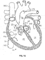
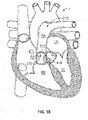
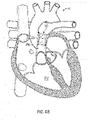
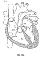
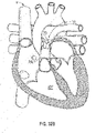
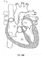
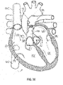
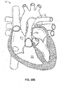
- FIGS 1A and 1B are cutaway views of the human heart H in diastolic and systolic phases, respectively.
- the right ventricle RV and left ventricle LV are separated from the right atrium RA and left atrium LA, respectively, by the tricuspid valve TV and mitral valve MV; i.e., the atrioventricular valves.
- the aortic valve AV separates the left ventricle LV from the ascending aorta (not identified) and the pulmonary valve PV separates the right ventricle from the pulmonary artery PA.
- Each of these valves has flexible leaflets extending inward across the respective orifices that come together or "coapt" in the flowstream to form the one-way, fluid-occluding surfaces.
- the docking stations and valves of the present application are described primarily with respect to the pulmonary valve. Therefore, anatomical structures of the right atrium RA and right ventricle RV will be explained in greater detail.
- the devices described herein may also be used in other areas, e.g., in the inferior vena cava and/or the superior vena cava as treatment for a regurgitant or otherwise defective tri-cuspid valve, in the aorta (e.g., an enlarged aorta) as treatment for a defective aortic valve, in other areas of the heart or vasculature, in grafts, etc.
- aorta e.g., an enlarged aorta
- the right atrium RA receives deoxygenated blood from the venous system through the superior vena cava SVC and the inferior vena cava IVC, the former entering the right atrium from above, and the latter from below.
- the coronary sinus CS is a collection of veins joined together to form a large vessel that collects deoxygenated blood from the heart muscle (myocardium), and delivers it to the right atrium RA.
- the venous blood that collects in the right atrium RA enters the tricuspid valve TV by expansion of the right ventricle RV.
- the right ventricle RV contracts to force the venous blood through the pulmonary valve PV and pulmonary artery into the lungs.
- the devices described by the present application are used to replace or supplement the function of a defective pulmonary valve.
- the leaflets of the tricuspid valve TV close to prevent the venous blood from regurgitating back into the right atrium RA.
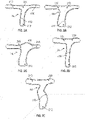
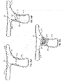
- the shown, non-exhaustive examples illustrate that the pulmonary artery can have a wide variety of different shapes and sizes.
- the length L, diameter, D, and curvature or contour may vary greatly between pulmonary arteries of different patients.
- the diameter D may vary significantly along the length L of an individual pulmonary artery.
- Tetralogy of Fallot is a cardiac anomaly that refers to a combination of four related heart defects that commonly occur together.
- the four defects are ventricular septal defect (VSD), overriding aorta (the aortic valve is enlarged and appears to arise from both the left and right ventricles instead of the left ventricle as in normal hearts), pulmonary stenosis (narrowing of the pulmonary valve and outflow tract or area below the valve that creates an obstruction of blood flow from the right ventricle to the pulmonary artery), and right ventricular hypertrophy (thickening of the muscular walls of the right ventricle, which occurs because the right ventricle is pumping at high pressure).
- VSD ventricular septal defect
- overriding aorta the aortic valve is enlarged and appears to arise from both the left and right ventricles instead of the left ventricle as in normal hearts
- pulmonary stenosis narrowing of the pulmonary valve and outflow tract or area below the valve that creates an obstruction of
- TGA Transposition of the Great Arteries
- Surgical treatment for some conditions involves a longitudinal incision along the pulmonary artery, up to and along one of the pulmonary branches. This incision can eliminate or significantly impair the function of the pulmonary valve.
- a trans-annular patch is used to cover the incision after the surgery.
- the trans-annular patch reduces stenotic or constrained conditions of the pulmonary artery PA, associated with other surgeries.
- the impairment or elimination of the pulmonary valve PV can create significant regurgitation and, prior to the present invention, often required later open heart surgery to replace the pulmonary valve.
- the trans-annular patch technique can result in pulmonary arteries having a wide degree of variation in size and shape (See Figures 3A-3D )
- an expandable docking station 10 includes one or more sealing portions 410, a valve seat 18, and one or more retaining portions 414.
- the sealing portion(s) 410 provide a seal between the docking station 10 and an interior surface 416 of the circulatory system.
- the valve seat 18 provides a supporting surface for implanting or deploying a valve 29 in the docking station 10 after the docking station 10 is implanted in the circulatory system.
- the retaining portions 414 help retain the docking station 10 and the valve 29 at the implantation position or deployment site in the circulatory system.
- Expandable docking station 10 and valve 29 as described in the various embodiments herein are also representative of a variety of docking stations and/or valves that might be known or developed, e.g., a variety of different types of valves could be substituted for and/or used as valve 29 in the various docking stations.
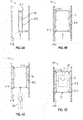
- FIGs 4A-4D schematically illustrate an exemplary deployment of the docking station 10 and valve 29 in the circulatory system.
- the docking station 10 is in a compressed form/configuration and is introduced to a deployment site in the circulatory system.
- the docking station 10 may be positioned at a deployment site in a pulmonary artery by a catheter (e.g., catheter 3600 as shown in Figures 50A-50D ).
- the docking station 10 is expanded in the circulatory system such that the sealing portion(s) 410 and the retaining portions 414 engage the inside surface 416 of a portion of the circulatory system.
- the valve 29 is in a compressed form and is introduced into the valve seat 18 of the docking station 10.
- the valve 29 is expanded in the docking station, such that the valve 29 engages the valve seat 18.
- the docking station 10 is longer than the valve.
- the docking station 10 can be the same length or shorter than the length of the valve 29.
- the valve seat 18 can be longer, shorter, or the same length as the length of the valve 29.
- valve 29 has expanded such that the seat 18 of the docking station supports the valve.
- the valve 29 only needs to expand against the narrow seat 18, rather than against the wider space within the portion of the circulatory system that the docking station 10 occupies.
- the docking station 10 allows the valve 29 to operate within the expansion diameter range for which it is designed.
- Figure 4E illustrates that the inner surface 416 of the circulatory system, such as the inner surface of a blood vessel or anatomy of the heart can vary in cross-section size and/or shape along its length.
- the docking station 10 is configured to expand radially outwardly to varying degrees along its length L to conform to shape of the inner surface 416.
- the docking station 10 is configured such that the sealing portion(s) 410 and/or the retaining portion(s) engage the inner surface 416, even though the shape of the blood vessel or anatomy of the heart vary significantly along the length L of the docking station.
- the docking station can be made from a very resilient or compliant material to accommodate large variations in the anatomy.
- the docking station can be made from a highly flexible metal, metal alloy, polymer, or an open cell foam.
- a metals and metal alloys that can be used include, but are not limited to, nitinol, elgiloy, and stainless steel, but other metals and highly resilient or compliant non-metal materials can be used.
- the docking station 10 can have a frame or portion of a frame (e.g., a self-expanding frame, retaining portion(s), sealing portion(s), valve seat, etc.) made of these materials, e.g., from shape memory materials, such as nitinol. These materials allow the frame to be compressed to a small size, and then when the compression force is released, the frame will self-expand back to its pre-compressed diameter.
- an open cell foam that can be used to form the docking station or a portion of the docking station is a bio-compatible foam, such as a polyurethane foam (e.g., as may be obtained from Biomerix, Rockville, MD).
- Docking stations described herein can be self expanding and/or expandable with an inflatable device to cause the docking station to engage an inner surface 416 having a variable shape.
- Figure 4F illustrates the docking station 10 and a valve 29 implanted in a pulmonary artery PA.
- the shape of the pulmonary artery may vary significantly along its length.
- the docking station 10 is configured to conform to the varying shape of the pulmonary artery PA in the same manner as described with respect to Figure 4E .
- an expandable docking station 10 is made from an expandable foam material, such as an open cell biocompatible foam.
- the outer surface 510 of the foam material can serve as the sealing portion 410.
- a valve seat 18 can be provided on the inner surface 512 of the foam material as illustrated, or the inner surface 512 can serve as the valve seat.
- the retaining portions 414 are omitted, though retaining portions can be used.
- foam material can be used together with an expandable frame (e.g., of metal, shape memory material, etc.). The foam material can cover or extend the full length of the frame or only a portion of the length of the frame.
- FIGs 5A-5D schematically illustrate deployment of the foam docking station 10 and valve 29 in the circulatory system.
- the docking station 10 is in a compressed form and is introduced to a deployment site in the circulatory system.
- the docking station 10 may be positioned at a deployment site in a pulmonary artery by a catheter (e.g., catheter 3600 shown in Figures 50A-50D ).
- the docking station 10 is expanded in the circulatory system such that the sealing portion 410 engage the inside surface 416 of the circulatory system.
- the valve 29 is in a compressed form and is introduced into the valve seat 18 or inner surface 512 of the docking station 10.
- the valve 29 is expanded in the docking station, such that the valve 29 engages the valve seat 18 or inner surface 512 (e.g., where inner surface 512 acts as the valve seat).
- Figure 5E illustrates that the inner surface 416 of the circulatory system, such as the inner surface of a blood vessel or anatomy of the heart may vary in cross-section along its length.
- the foam docking station 10 is configured to expand radially outwardly to varying degrees along its length L to conform to shape of the inner surface 416.
- Figure 5F illustrates the foam docking station 10 and a valve 29 implanted in a pulmonary artery PA.
- the shape of the pulmonary artery may vary significantly along its length.
- the docking station 10 is configured to conform to the varying shape of the pulmonary artery PA in the same or a similar manner as described with respect to Figure 4E .
- a docking station e.g., a docking station as described with respect to Figures 4A-4D
- Figure 6B illustrates a valve 29 deployed in the docking station 10 illustrated by Figure 6A .
- the heart is in the systolic phase.
- Figure 7A is an enlarged representation of the docking station 10 and valve 29 in the pulmonary artery 29 of Figure 6B .
- the valve 29 opens. Blood flows from the right ventrical RV and through the pulmonary artery PA, docking station 10, and valve 29 as indicated by arrows 602.
- Figure 7B illustrates space 608 that represents the valve 29 being open when the heart is in the systolic phase.
- Figure 7B does not show the interface between the docking station 10 and the pulmonary artery to simplify the drawing.
- the cross-hatching in Figure 7B illustrates blood flow through the open valve.
- blood is prevented from flowing between the pulmonary artery PA and the docking station 10 by the sealing portion(s) 410 and blood is prevented from flowing between the docking station 10 and the valve 29 by seating of the valve 29 in the seat 18 of the docking station 10.
- blood is substantially only flowing or only able to flow through the valve 29 when the heart is in the systolic phase.
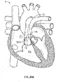
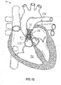
- Figure 8 illustrates the valve 29, docking station 10 and heart H illustrated by Figure 6B , when the heart is in the diastolic phase.
- Figure 9A and 9B when the heart is in the diastolic phase, the valve 29 closes.
- Figure 9A is an enlarged representation of the docking station 10 and valve 29 in the pulmonary artery 29 of Figure 8 . Blood flow in the pulmonary artery PA above the valve 29 (i.e. in the pulmonary branch 760) is blocked by the valve 29 being closed and blocking blood flow as indicated by arrow 900.
- the solid area 912 in Figure 9B represents the valve 29 being closed when the heart is in the diastolic phase.
- the docking station 10 acts as an isolator that prevents or substantially prevents radial outward forces of the valve 29 from being transferred to the inner surface 416 of the circulatory system.
- the docking station 10 includes a valve seat 18 (which is not expanded radially outwardly or is not substantially expanded radially outward by the radially outward force of the THV or valve 29, i.e., the diameter of the valve seat is not increased or is increased by less than 4 mm by the force of the THV), and anchoring/retaining portions 414 and sealing portions 410, which impart only relatively small radially outward forces 720, 722 on the inner surface 416 of the circulatory system (as compared to the radially outward force applied to the valve seat 18 by the valve 29).
- stents and frames of THVs are held in place in the circulatory system by a relatively high radial outward force 710 of the stent or frame 712 of the THV acting directly on the inside surface 416 of the circulatory system.
- a docking station is used, as in the example illustrated by Figure 7A , the stent or frame 712 of the valve 29 expands radially outward or is expanded radially outward to impart the high force 710 on the valve seat 18 of the docking station 10.
- This high radially outward force 710 secures the valve 29 to the valve seat 18 of the docking station 10.
- the force 710 is isolated from the circulatory system, rather than being used to secure the docking station in the circulatory system.
- the radially outward force 722 of the sealing portions 410 to the inside surface 416 is substantially smaller than the radially outward force 710 applied by the valve 29 to the valve seat 18.
- the radially outward sealing force 722 can be less than 1 ⁇ 2 the radially outward force 710 applied by the valve, less than 1/3 the radially outward force 710 applied by the valve, less than 1/4 the radially outward force 710 applied by the valve, less than 1/8, or even less than 1/10 the radially outward force 710 applied by the valve.
- the radially outward force 722 of the sealing portions 410 is selected to provide a seal between the inner surface 416 and the sealing portion 410, but is not sufficient by itself to retain the position of the valve 29 and docking station 10 in the circulatory system.
- the radially outward force 720 of the anchoring/retaining portions 414 to the inside surface 416 is substantially smaller than the radially outward force 710 applied by the valve 29 to the valve seat 18.
- the radially outward sealing force 720 can be less than 1 ⁇ 2 the radially outward force 710 applied by the valve, less than 1/3 the radially outward force 710 applied by the valve, less than 1/4 the radially outward force 710 applied by the valve, less than 1/8, or even less than 1/10 the radially outward force 710 applied by the valve.
- the radially outward force 720 of the retaining portions 414 is not sufficient by itself to retain the position of the valve 29 and docking station 10 in the circulatory system. Rather, the pressure of the blood 608 is used to enhance the retention of the retaining portions 414 to the inside surface 416.
- the valve 29 is open and blood flows through the valve as indicated by arrows 602. Since the valve 29 is open and blood flows through the valve 29, the pressure P applied to the docking station 10 and valve 29 by the blood is low as indicated by the small P and arrow in Figure 7A .
- the force applied by the upper and lower retaining portions 414 is determined by amount of pressure applied to the valve 29 and docking station 10 by the blood, the force applied to the surface 416 is automatically proportioned. That is, the upper retaining portions are less forcefully pressed against the surface 416 when the heart is in the systolic phase than the lower retaining portions are pressed against the surface 416 when the heart is in the diastolic phase. This is because the pressure against the open valve 29 and docking station 10 in the systolic phase is less than the pressure against the closed valve and docking station in the diastolic phase.
- valve seat 18 and sealing portion 410 can take a wide variety of different forms.
- the valve seat 18 can be any structure that is not expanded radially outwardly or is not substantially expanded radially outward by the radially outward force of the THV (i.e., the diameter of the valve seat in the deployed position/configuration may not expand or may expand less than 4mm, e.g., the diameter may only expand 1-4 mm larger when the valve is deployed in the valve seat).
- the valve seat 18 can comprise a suture or a metal ring that resists or limits expansion.
- the valve seat 18 (or any valve seat described herein) can be expandable over a larger range, for example, the diameter may expand between 5mm and 30mm larger when a valve is deployed in the valve seat.
- the diameter might expand from 5mm or 6mm in diameter to 20mm-29mm, 24mm, 26mm, 29mm, etc. in diameter, or expand from and to different diameters within that range.
- the valve seat can still be restricted in expansion, e.g., restricted to avoid expansion of the valve seat beyond an expanded diameter of a valve to be placed in the valve seat or to avoid expansion beyond a diameter that will securely hold the valve in the valve seat via the forces created therebetween.
- the valve seat 18 can be part of or define a portion of the body of the docking station 10, or the valve seat 18 can be a separate component that is attached to the body of the docking station.
- the valve seat 18 can be longer, shorter, or the same length as the valve.
- the valve seat 18 can be significantly shorter than the valve 29 when the valve seat 18 is defined by a suture or a metal ring.
- a valve seat 18 formed by a suture or metal ring can form a narrow circumferential seal line between the valve 29 and the docking station.
- the sealing portion(s) 410 of various embodiments can take a wide variety of different forms.
- the sealing portion(s) 410 can be any structure that provides a seal(s) between the docking station 10 and the surface 416 of the circulatory system.
- the sealing portion(s) 410 can comprise a fabric, a foam, biocompatible tissue, a combination of these, etc.
- the sealing portion(s) 410 can be part of or define a portion of the body of the docking station 10, and/or the sealing portion(s) 410 can be a separate component that is attached to the body of the docking station.
- the docking station 10 may include a single sealing portion 410 or two, or more than two sealing portions.
- the sealing portion(s) 410 is configured to apply a low radially outward force to the surface 416.
- the low radially outward force can be provided in a wide variety of different ways.
- sealing portion may be made from a very compressible or compliant material.
- the docking station 10 body is made from an elastic or superelastic metal.
- One such metal is nitinol.
- the body of a docking station 10 is made from a lattice of metal struts, the body can have the characteristics of a spring.
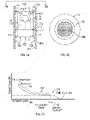
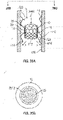
- the body of the docking station when the body of the docking station is unconstrained and allowed to relax to its largest diameter the body of the docking station applies little or no radially outward force. As the body of the docking station 10 is compressed, like a spring, the radially outward force applied by the docking station increases. As is illustrated by Figure 7C , in one exemplary embodiment the relationship of the radially outward force of the docking station body to the expanded diameter of the docking station is non-linear, although, in one exemplary embodiment, the relationship could also be linear. In the example illustrated by Figure 7C , the curve 750 illustrates the relationship between the radially outward force exerted by the docking station 10 and the compressed diameter of the docking station.
- the curve 750 has a low slope. In this region 752 the radially outward force is low and changes only a small amount. In one exemplary embodiment, the region 752 corresponds to a diameter between 25mm and 40 mm, such as between 27mm and 38mm. The radially outward force is small in the region 752, but is not zero. In the region 754, the curve 750 has a higher slope. In this region 754 the radially outward force increases significantly as the docking station is compressed. In one exemplary embodiment, the body of the stent is constructed to be in the low slope region 752. This allows the sealing portions 710 to apply only a small radially outward force to the inner surface 416 of the circulatory system over a wide range of diameters.
- the retaining portions 414 can take a wide variety of different forms.
- the retaining portion(s) 414 may be any structure that sets the position of the docking station 10 in the circulatory system.
- the retaining portion(s) 414 may press against or into the inside surface 416 or extend around anatomical structure of the circulatory system to set the position of the docking station 10.
- the retaining portion(s) 414 may be part of or define a portion of the body of the docking station 10 or the retaining portion(s) 414 may be a separate component that is attached to the body of the docking station.
- the docking station 10 may include a single retaining portion 414 or two, or more than two retaining portions.
- FIGS 10A-10C illustrate that the docking station 10 can have any combination of one or more than one different types of valve seats 18 and sealing portions 410.
- the valve seat 18 is a separate component that is attached to the body of the docking station 10 and the sealing portion is integrally formed with the body of the docking station.
- the valve seat 18 is a separate component that is attached to the body of the docking station 10 and the sealing portion 410 is a separate component that is attached to the body of the docking station.
- the valve seat 18 is integrally formed with the body of the docking station 10 and the sealing portion is integrally formed with the body of the docking station.
- the valve seat 18 is integrally formed with the body of the docking station 10 and the sealing portion is a separate component that is attached to the body of the docking station 10.
- the length of the pulmonary artery PA and other anatomical structures of the circulatory system may vary greatly from patient to patient.
- the length of the docking station 10 is adjustable as indicated by arrow 1100.
- This adjustability 1100 refers to the ability of the implanted/expanded length of the docking station to be adjusted, rather than the inherent change in length that occurs when a stent expands from a compressed state to an expanded state.
- the length may be adjusted in a wide variety of different ways.
- the docking station 10 includes a first half 1102 and a second half 1104.
- the word "half' as used herein with respect to two part docking stations is synonymous with "portion" and does not require the first and second half or first and second portion to be equal in size, i.e., the first half could be larger/longer than the second half and vice versa.
- the second half 1104 can be inserted or "telescoped" into the first half 1102.
- the amount of insertion or "telescoping” sets the length of the docking station 10.
- Any of the docking stations 10 shown and described in this patent application can be adjustable in length by making the docking stations from two parts that are telescoped together or are otherwise adjustable relative to each other.
- a length of a single-piece docking station can be collapsible and expandable.
- a docking station may be formed of a material that can change shape to adjust the length.
- more than two portions e.g., 3, 4, or more portions
- the length of the docking station 10 can be adjusted in the pulmonary artery PA by first deploying the first half 1102 of the docking station 10 in the pulmonary artery.
- the first half 1102 may be positioned and expanded as desired, e.g., such that a distal end 1106 of the first half is aligned with or extends somewhat past the branch of the pulmonary artery.
- the compressed second half 1104 can be positioned with a distal end 1110 disposed in the proximal end 1108 of the first half 1102.
- the position of the second half 1104 is selected such that the sealing portion 410 and retaining portion 414 will make contact with the pulmonary artery and set the position of the docking station 10 in the pulmonary artery.
- the second half 1104 is expanded.
- the distal end of 1110 of the second half 1104 frictionally engages the proximal end 1108 of the first half to secure the two halves 1102, 1104 together.
- a lock(s), locking mechanism, suture(s), interlacing, link(s) and/or other attachment device/mechanism may be used to help secure the halves/portions together.
- the seat 18 and the sealing portion 410 are included on the second half 1104 of the docking station 10.
- the seat 18 and/or the sealing portion 410 can be included on the first half 1102.
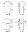
- Figures 11A-11C illustrate that the halves 1102, 1104 of the docking station 10 can have any combination of different types of valve seats 18 and sealing portions 410.
- the valve seat 18 is a separate component that is attached to the body of the docking station half 1104 and the sealing portion is integrally formed with the body of the docking station half 1104.
- valve seat 18 is a separate component that is attached to the body of the docking station half 1104 and the sealing portion 410 is a separate component that is attached to the body of the docking station half 1104.
- the valve seat 18 is integrally formed with the body of the docking station half 1104 and the sealing portion is integrally formed with the body of the docking station half 1104.
- the valve seat 18 is integrally formed with the body of the docking station half 1104 and the sealing portion 410 is a separate component that is attached to the body of the docking station half 1104.
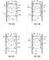
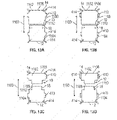
- FIGs 12A-12D illustrate exemplary embodiments of docking stations 10 with two sealing portions 410.
- the docking station 10 can have any combination of one or more than one different types of valve seats 18 and sealing portions 410.
- the valve seat 18 is a separate component that is attached to the body of the docking station 10 and the sealing portions 410 is integrally formed with the body of the docking station.
- the valve seat 18 is a separate component that is attached to the body of the docking station 10 and the sealing portions 410 are separate components that are attached to the body of the docking station.
- valve seat 18 is integrally formed with the body of the docking station 10 and the sealing portions are integrally formed with the body of the docking station.
- valve seat 18 is integrally formed with the body of the docking station 10 and the sealing portions are separate components that are attached to the body of the docking station 10.
- Figures 13A-13D illustrate that the docking stations illustrated by Figures 12A-12D can be two-piece telescoping docking stations.
- the pieces 1102, 1104 of the docking station 10 can have any combination of one or more than one different types of valve seats 18 and sealing portions 410 on either or both of the two pieces.
- the first half 1102 includes an integral sealing portion 410.
- the second half 1104 includes a valve seat 18 that is a separate component that is attached to the body of the docking station 10 and the sealing portions 410 is integrally formed with the body of the docking station.
- the first half 1102 includes a sealing portion 410 that is separate from the body of the first half 102.
- the valve seat 18 is a separate component that is attached to the body of the docking station 10 and the sealing portion 410 is a separate components that is attached to the body of the docking station.
- the first half 1102 includes an integral sealing portion 410.
- the valve seat 18 is integrally formed with the body of the second half 1104 of the docking station 10 and the sealing portion 410 is integrally formed with the body of the second half 1104.
- the first half 1102 includes a sealing portion 410 that is separate from the body of the first half 102.
- the valve seat 18 is integrally formed with the body of the second half 1104 of the docking station 10 and the sealing portion 410 is a separate components that is attached to the body of the second half 1104.
- the docking station 10 can include a permeable portion 1400 that blood can flow through as indicated by arrows 1402 and an impermeable portion 1404 that blood cannot flow through.
- the impermeable portion 1404 extends from at least the sealing portion 410 to the valve seat 18 to prevent blood from flowing around the valve 29.
- the permeable portion 1400 allows blood to freely flow through it, so that portions of the docking station that do not seal against the inside surface 416 of the circulatory system or seal against the valve 29 do not block the flow of blood.
- the docking station 10 may extend into the branch of the pulmonary artery and the portion 1400 of the docking station 10 that extends into the pulmonary artery freely allows blood to flow through the docking station 10.
- the permeable portion 1400 allows blood to freely flow through it, so that areas 1420 between the docking station and the circulatory system are flushed with blood as the heart beats, thereby preventing blood stasis in the areas 1420.
- the impermeable portion 1404 can take a wide variety of different forms.
- the impermeable portion 1404 may be any structure or material that prevents blood to flow through the impermeable portion 1404.
- the body of the docking station 10 can be formed from wires or a lattice, such as a nitinol wire or lattice, and cells of body are covered by an impermeable material (See Figure 18 ).
- an impermeable material See Figure 18 .
- a wide variety of different materials may be used as the impermeable material.
- the impermeable material may be a blood-impermeable cloth, such as a PET cloth or biocompatible covering material such as a fabric that is treated with a coating that is impermeable to blood, polyester, or a processed biological material, such as pericardium.
- a blood-impermeable cloth such as a PET cloth
- biocompatible covering material such as a fabric that is treated with a coating that is impermeable to blood, polyester, or a processed biological material, such as pericardium.
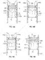
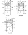
- FIGs 14A-14G illustrate that a wide variety of docking station configurations can be provided with a permeable portion 1402.
- the sealing portion 410 may be integrally formed with the body of the docking station as illustrated by Figures 14B, 14D , and 14F or separate as illustrated by Figures 14C , 14E and 14G .
- the docking station 10 includes portions 1410. These portions 1410 are similar to the sealing portions 410, but a seal is not formed with the inner surface 416 of the circulatory system, because the portion 1410 is part of the permeable portion 1402.
- the valve seat 18 may be separately formed from the body of the docking station as illustrated by Figures 14A-14C or integrally formed with the body of the docking station 10 as illustrated by Figures 14D-14G .
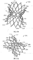
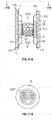
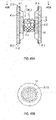
- Figures 15A, 15B , 16 , 17A, and 17B illustrate an exemplary embodiment of a frame 1500 or body of a docking station 10.
- the frame 1500 or body can take a wide variety of different forms and Figures 15A, 15B , 16 , 17A, and 17B illustrate just one of the many possible configurations.
- the docking station 10 has a relatively wider proximal inflow end 12 and distal outflow end 14, and a relatively narrower portion 16 that forms the seat 18 in between the ends 12, 14.
- the frame 1500 of the docking station 10 is preferably a wide stent comprised of a plurality of metal struts 1502 that form cells 1504.
- the frame 1500 has a generally hourglass-shape that has a narrow portion 16, which forms the valve seat 18 when covered by an impermeable material, in between the proximal and distal ends 12, 14. As described below, the valve 18 expands in the narrow portion 16, which forms the valve seat 18.
- Figures 15A, 15B , 17A, and 17B illustrate the frame 1500 in its unconstrained, expanded condition.
- the retaining portions 414 comprise ends 1510 of the metal struts 1502 at the proximal and distal ends 12, 14.
- the sealing portion 410 is between the retaining portions 414 and the waist 16.
- the retaining portions 414 extend generally radially outward and are radially outward of the sealing portion 410.
- Figure 16 illustrates the frame 16 in the compressed state for delivery and expansion by a catheter.
- the docking station can be made from a very resilient or compliant material to accommodate large variations in the anatomy.
- the docking station can be made from a highly flexible metal, metal alloy, polymer, or an open cell foam.
- the docking station 10 may be self expanding, manually expandable (e.g., expandable via balloon), or mechanically expandable.
- a self-expanding docking station 10 may be made of a shape memory material such as, for example, nitinol.
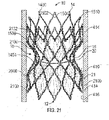
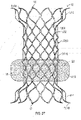
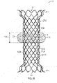
- FIG 18 illustrates the frame 1500 with impermeable material 21 attached to the frame 1500 to form the docking station 10.
- a band 20 extends about the waist or narrow portion 16, or is integral to the waist to form an unexpandable or substantially unexpandable valve seat 18.
- the band 20 stiffens the waist and, once the docking station is deployed and expanded, makes the waist/valve seat relatively unexpandable in its deployed configuration.
- the valve 29 is secured by expansion of its collapsible frame into the narrow portion 16, which forms the valve seat 18, of the docking station 10.
- the unexpandable or substantially unexpandable valve seat 18 prevents the radially outward force of the valve 29 from being transferred to the inside surface 416 of the circulatory system.
- the waist/valve seat of the deployed docking station may optionally expand slightly in an elastic fashion when the valve is deployed against it. This optional elastic expansion of the waist 18 may put pressure on the valve 29 to help hold the valve 29 in place within the docking station.
- the band can take a wide variety of different forms and can be made from a wide variety of different materials.
- the band 20 can be made of PET, one or more sutures, fabric, metal, polymer, a biocompatible tape, or other relatively unexpandable materials known in the art that are sufficient to maintain the shape of the valve seat 18 and hold the valve 29 in place.
- the band can extend about the exterior of the stent, or can be an integral part of it, such as when fabric or another material is interwoven into or through cells of the stent.
- the band 20 may be narrow, such as the suture band in Figure 18 , or may be wider.
- the band can be a variety of widths, lengths, and thicknesses.
- valve seat 18 is between 27-28 mm wide, although the diameter of the valve seat should be within the operating range of the particular valve 29 that will be secured within the valve seat 18, and can be different than the foregoing example.
- the valve 29, when docked within the docking station, can optionally expand around either side of the valve seat slightly. This aspect, sometimes referred to as a "dogbone" (e.g., because of the shape it forms around the valve seat or band), can also help hold the valve in place.
- Figures 20 and 21 illustrate the docking station 10 of Figure 18 implanted in the circulatory system, such as in the pulmonary artery.
- the sealing portions 410 provide a seal between the docking station 10 and an interior surface 416 of the circulatory system.
- the sealing portion 410 is formed by providing an impermeable material 21 (See Figure 21 ) over the frame 1500 or a portion thereof,
- the sealing portion 410 can comprise the lower, rounded, radially outward extending portion 2000 of the frame 1500.
- the impermeable material 21 extends from at least the portion 2000 of the frame 1500 to the valve seat 18. This makes the docking station impermeable from the sealing portion 410 to the valve seal 18. As such, all blood flowing in the inflow direction 12 toward the outflow direction 14 is directed to the valve seat 18 (and valve 29 once installed or deployed in the valve seat).
- the inflow portion has walls that are impermeable to blood, but the outflow portion walls are relatively open.
- the inflow end portion 12, the mid-section 16, and a portion of the outflow end portion 14 are covered with a blood-impermeable fabric 21, which may be sewn onto the stent or otherwise attached by a method known in the art.
- the impermeability of the inflow portion of the stent helps to funnel blood into the docking station 10 and ultimately flow through the valve that is to be expanded and secured within the docking station 10.
- this embodiment of a docking station is designed to seal at the proximal inflow section 2000 to create a conduit for blood flow.
- the distal outflow section is generally left open, thereby allowing the docking station 10 to be placed higher in the pulmonary artery without restricting blood flow.
- the permeable portion 1400 may extend into the branch of the pulmonary artery and not impede or not significantly impede the flow of blood past the branch.
- blood-impermeable cloth such as a PET cloth for example, or other material covers the proximal inflow section, but the covering does not cover any or at least a portion of the distal outflow section 14.
- the cloth covering 21 is fluid impermeable so that blood cannot pass through.
- biocompatible covering materials such as, for example, foam or a fabric that is treated with a coating that is impermeable to blood, polyester, or a processed biological material, such as pericardium.
- more of the docking station frame 1500 is provided with the impermeable material 21, forming a relatively large impermeable portion 1404.
- the impermeable portion 1404 extends from the inflow end 12 and stops one row of cells 1504 before the outflow end. As such, the most distal row of cells 1504 form a permeable portion 1400. However, more rows of cells 1504 can be uncovered by the impermeable material to form a larger permeable portion.
- the permeable portion 1400 allows blood to flow into and out of the area 2130 as indicated by arrows 2132.
- the cells 1504 are generally diamond shaped, blood is able to flow between the docking station 10 and the surface 416, until the sealing portion 410 is reached. That is, blood can flow into and out of the areas 2100 in one exemplary embodiment.
- the valve seat 18 can provide a supporting surface for implanting or deploying a valve 29 in the docking station 10.
- the retaining portions 414 can retain the docking station 10 at the implantation position or deployment site in the circulatory system.
- the illustrated retaining portions have an outwardly curving flare that helps secure the docking station 10 within the artery. "Outwardly” as used herein means extending away from the central longitudinal axis of the docking station.
- the retaining portions 414 engage the surface 416 at an angle ⁇ (normal to the surface to the tangent of the midpoint of the surface of the retaining portion 414) that can be between 30 and 60 degrees, such as about 45 degrees, rather than extending substantially radially outward (i.e. ⁇ is 0 to 20 degrees or about 10 degrees) as in the uncompressed condition (See Figure 15B ).
- This inward bending of the retaining portions 414 as indicated by arrow 2020 acts to retain the docking station 10 in the circulatory system.
- the retaining portions 14 are at the wider inflow end portion 12 and outflow end portion 14 and press against the inner surface 416.
- the flared retaining portions 414 engage into the surrounding anatomy in the circulatory system, such as the pulmonic space.
- the flares serve as a stop, which locks the device in place.
- the flared retaining portions 414 are pushed by the force into the surrounding tissue to resist migration of the stent as described in more detail below.
- the docking station generally has an hourglass shape, with wider distal and proximal end portions that have the flared retaining portion and a narrow, banded waist in between the ends, into which the valve is expanded.
- FIG 22 illustrates the docking station 10 deployed in the circulatory system and a valve 29 deployed in the docking station 10.
- the valve 29 is in a compressed form and is introduced into the valve seat 18 of the docking station 10.
- the valve 29 is expanded in the docking station, such that the valve 29 engages the valve seat 18.
- the docking station 10 is longer than the valve.
- the docking station 10 may be the same length or shorter than the length of the valve 10.
- the valve 29 may be delivered to the site of the docking station via conventional means, such as by balloon or mechanical expansion or by self-expansion. When the valve 29 is expanded, it nests in the valve seat of the docking station 10.
- the banded waist is slightly elastic and exerts an elastic force against the valve 29, to help hold the THV in place.
- FIGS 23A and 23B illustrate that the docking station 10 can be used to adapt a variety of different sizes of circulatory system anatomies for implantation of a valve 29 having a consistent size.
- the same size docking station 10 is deployed in two different sized vessels 2300, 2302, such as two differently sized pulmonary arteries PA.
- the vessel 2300 illustrated by Figure 23A has a larger effective diameter than the vessel 2302 illustrated by Figure 23B .
- the size of the anatomy of the circulatory system is referred to by the term "diameter" or "effective diameter.”
- the anatomy of the circulatory system is often not circular.
- diameter and “effective diameter” herein refers to the diameter of a circle or disc that could be deformed to fit within the non-circular anatomy.)
- the sealing portion 410 and the retaining portions 414 conform to contact each vessel 2300, 2302.
- the valve seat 18 remains the same size, even though the sealing portion 410 and the retaining portions 414 are compressed. In this manner, the docking station 10 adapts a wide variety of different anatomical sizes for implantation of a standard or single sized valve.
- the docking station may conform to vessel diameters of 25mm and 40 mm, such as 27mm and 38mm and provide a constant or substantially constant diameter valve seat of 24mm to 30mm, such as 27mm to 28mm.
- the valve seat 10 can be adapted for applications where the vessel diameter is larger or smaller than 25mm to 40 mm and provide valve seats that are larger or smaller than 24mm to 30mm.
- a band 20 maintains a constant or substantially constant diameter of the valve seat 18, even as the proximal and distal ends of the docking station expand to respective diameters necessary to engage with the inside surface 416.
- the diameter of the pulmonary artery PA can vary considerably from patient to patient, but the valve seat 18 in the deployed configuration consistently has a diameter that is within an acceptable range for the valve 29.
- FIGs 24 and 25 illustrate side profiles of the docking station 10 illustrated by Figure 18 when implanted in different sized vessels 2300, 2302 of the circulatory system with a schematically illustrated transcatheter heart valve 29 having the same size installed or deployed in each docking station 10.
- the docking station 10 both accommodates vessels 2300, 2302 having a variety of different sizes and acts as an isolator that prevents or substantially prevents radial outward forces of the valve 29 from being transferred to the vessels.
- the valve seat 18 is not expanded radially outwardly or is not substantially expanded radially outward by the radially outward force of the valve 29 and the anchoring/retaining portions 414 and the sealing portions 410 impart only relatively small radially outward force on the vessels 2300, 2302 (as compared to the radially outward force applied to the valve seat 18 by the valve 29), even when the docking station is deployed in a vessel 2302 having a smaller diameter.
- the stent or frame 712 of the valve 29 expands radially outward or is expanded radially outward to import the high force 710 on the valve seat 18 of the docking station 10.
- This high radially outward force 710 secures the valve 29 to the valve seat 18 of the docking station 10.
- the force 710 is isolated from the circulatory system, rather than being used to secure the docking station in the circulatory system.
- the radially outward force 722 of the sealing portions 410 to both the larger vessel 2300 and the smaller vessel is substantially smaller than the radially outward force 710 applied by the valve 29 to the valve seat 18.
- the radially outward sealing force 722 can be less than 1 ⁇ 2 the radially outward force 710 applied by the valve, less than 1/3 the radially outward force 710 applied by the valve, less than 1/4 the radially outward force 710 applied by the valve, less than 1/8, or even less than 1/10 the radially outward force 710 applied by the valve.
- the radially outward force 722 of the sealing portions 410 is selected to provide a seal between the inner surface 416 and the sealing portion 410, but is not sufficient by itself to retain the position of the valve 29 and docking station 10 in the circulatory system. In one embodiment, the radially outward force 722 is sufficient to retain the position of the valve 29 and docking station 10 in the circulatory system.
- the docking station 10 illustrated by Figure 18 also includes anchoring/retaining portions 414 that apply radially outward forces 720 that are substantially smaller than the radially outward force 710 applied by the valve 29 to the valve seat 18.
- the radially outward sealing force 720 can be less than 1 ⁇ 2 the radially outward force 710 applied by the valve, less than 1/3 the radially outward force 710 applied by the valve, less than 1/4 the radially outward force 710 applied by the valve, less than 1/8, or even less than 1/10 the radially outward force 710 applied by the valve.
- the radially outward force 720 of the anchoring/retaining portions 414 is not sufficient by itself to retain the position of the valve 29 and docking station 10 in the circulatory system. In one embodiment, the radially outward force 720 is sufficient to retain the position of the valve 29 and docking station 10 in the circulatory system.
- the docking station 10 frame 1500 is made from an elastic or superelastic material or metal.
- One such metal is nitinol.
- the body can have the characteristics of a spring. Referring to Figure 7C , like a spring, when the frame 1500 of the docking station 10 illustrated by Figures 24 and 25 is unconstrained and allowed to relax to its largest diameter the frame of the docking station applies little or no radially outward force. As the frame 1500 of the docking station 10 is compressed, like a spring, the radially outward force applied by the docking station increases.
- the relationship of the radially outward force of the docking station frame 1500 to the expanded diameter of the docking station is non-linear, though it can also be linear.
- the curve 750 illustrates the relationship between the radially outward force exerted by the docking station 10 and the compressed diameter of the docking station.
- the curve 750 has a low slope.
- the radially outward force is low and changes only a small amount.
- the region 752 corresponds to a diameter between 25mm and 40 mm, such as between 27mm and 38mm. The radially outward force is small in the region 752, but is not zero.
- the curve 750 has a higher slope. In this region 754 the radially outward force increases significantly as the docking station is compressed.
- the body of the stent is constructed to be in the low slope region 752 for both a largest vessel 2300 ( Figure 24 ) accommodated by the docking station 10 and a smallest vessel 2302 ( Figure 25 ). This allows the sealing portions 710 to apply only a small radially outward force to the inner surface 416 of the circulatory system over a wide range of diameters.
- Figures 26A-26C illustrate the docking station 10 of Figure 18 implanted in a pulmonary artery.
- Figure 26A illustrates the profile of the docking station 10 implanted in the pulmonary artery PA.
- Figure 26B illustrates the profile of the docking station 10 implanted in the pulmonary artery PA with a schematically illustrated valve 29 installed or deployed in the docking station 10.
- Figure 26C illustrates the docking station 10 and valve 29 as depicted in Figure 22 implanted in the pulmonary artery PA.
- the shape of the pulmonary artery may vary significantly along its length.
- the docking station 10 is configured to conform to the varying shape of the pulmonary artery PA.
- the docking station 10 is illustrated as being positioned below the pulmonary artery bifurcation or branch. However, often the docking station 10 will be positioned such that the end 14 extends into the pulmonary artery bifurcation 210. When it is contemplated that the docking station 10 will extend into the pulmonary artery bifurcation, the docking station 10 can have a blood permeable portion 1400 (e.g., as shown in Figure 21 ).
- FIG 27 illustrates another exemplary embodiment of a docking station 10.
- the docking station 10 includes a frame 2700 and an external sealing portion 410.
- the frame 2700 or body can take a wide variety of different forms and Figure 27 illustrates just one of the many possible configurations.
- the docking station 10 has a relatively wider proximal inflow end 12 and distal outflow end 14, and an elongated relatively narrower portion 2716.
- the seat 18 and sealing portion 410 can be provided anywhere along the length of the elongated relatively narrow portion 2716.
- the frame 2700 of the docking station 10 is preferably a stent comprised of a plurality of metal struts 1502 that form cells 1504.
- the frame 2700 or portion(s) of the frame can optionally be covered by an impermeable material 21 (e.g., as shown in Figure 18 ).
- Figure 27 illustrates the frame 2700 and sealing portion 410 in their unconstrained, expanded condition/configuration or deployed configuration.
- the retaining portions 414 comprise ends 1510 of the metal struts 1502 at the proximal and distal ends 12, 14.
- the sealing portion 410 can be a separate component that is disposed around the frame 2700 between the retaining portions 414. In the unconstrained condition, the retaining portions 414 extend generally radially outward and may be radially outward of the sealing portion 410.
- the docking station 10 illustrated by Figure 27 may be made from a very resilient or compliant material to accommodate large variations in the anatomy.
- the docking station may be made from a highly flexible metal (e.g., the frame in the Figure 27 example) and cloth and/or an open cell foam (e.g., the sealing portion in the Figure 27 example).
- An example of a highly resilient metal is nitinol, but other metals and highly resilient or compliant non-metal materials can be used.
- An example of an open cell foam that can be used is a biocompatible foam, such as a polyurethane foam (e.g., as may be obtained from Biomerix, Rockville, MD).
- a foam forming the sealing portion may also form a valve seat on its inner surface.
- the frame 2700 and/or the separate sealing portion 410 may include an optional a band 20 to form an unexpandable or substantially unexpandable valve seat 18.
- the frame 2700 may be configured to be substantially unexpandable in the area of the valve seat 18 without the use of a band 20.
- the optional band 20 stiffens the frame 2700 and/or sealing portion and makes the valve seat relatively unexpandable.
- the optional band 20 can take a wide variety of different forms, can be made from a wide variety of different materials, and can be the same as or similar to bands discussed elsewhere in this disclosure.
- the band 20 can be made of PET, one or more sutures, fabric, metal, polymer, a biocompatible tape, or other relatively unexpandable materials known in the art that are sufficient to maintain the shape of the valve seat 18 and hold the valve 29 in place.
- the band can extend about the exterior of the stent, or can be an integral part of it, such as when fabric or another material is interwoven into or through cells of the stent.
- the band 20 can be narrow, such as the suture band in Figure 18 , or can be wider as illustrate by the dashed line in Figure 27 .
- the valve seat 18 is between 27-28 mm in diameter, although the diameter of the valve seat should be within the operating range of the particular valve 29 that will be secured within the valve seat 18, and may be different than the foregoing example.
- Figures 28 and 29 illustrate a modified version of the docking station 10 illustrated by Figure 27 that is expandable in length.
- the length of the pulmonary artery PA and other anatomical structures of the circulatory system may vary greatly from patient to patient.
- the length of the docking station 10 is adjustable as indicated by arrow 1100. The length may be adjusted in a wide variety of different ways, e.g., it can be adjustable in any of the ways described elsewhere in this disclosure.
- the docking station 10 includes a first half 1102 and a second half 1104.
- the second half 1104 can be inserted or "telescoped" into the first half 1102. The amount of insertion or "telescoping" sets the length of the docking station 10.
- the length of the docking station 10 is adjusted in the pulmonary artery PA by first deploying the first half 1102 of the docking station 10 in the pulmonary artery.
- the first half 1102 may be positioned and expanded such that a distal end 1106 of the first half is aligned with or extends somewhat past the branch of the pulmonary artery.
- the compressed second half 1104 is positioned with a distal end 1110 disposed in the proximal end 1108 of the first half 1102.
- the position of the second half 1104 is selected such that the sealing portion 410 and retaining portion 414 will make contact with the pulmonary artery and set the position of the docking station 10 in the pulmonary artery.
- the second half 1104 is expanded.
- the distal end of 1110 of the second half 1104 frictionally engages the proximal end 1108 of the first half to secure the two halves 1102, 1104 together.
- a lock(s), locking mechanism, suture(s), interlacing, link(s) and/or other attachment device/mechanism may (also or alternatively) be used to secure the two halves together.
- the seat 18 and the sealing portion 410 are included on the first half 1102 of the docking station 10.
- the seat 18 and/or the sealing portion(s) 410 can be included on the second half 1104 or in different locations on the first half and/or the second half.
- Figures 30 and 31A illustrate the docking station 10 of Figure 27 of Figures 28 and 29 implanted in the circulatory system, such as in the pulmonary artery PA.
- the sealing portion 410 provides a seal between the docking station 10 and an interior surface 416 of the pulmonary artery PA.
- the sealing portion 410 is an expanding material, such as an expandable open cell foam over the frame 2700.
- the sealing portion 410 coincides or at least overlaps with the valve seat 18.
- an impermeable material 21 may be provided over a portion of the frame (e.g., from the sealing portion 410 to the valve seat 18 to make the docking station impermeable from the sealing portion 410 to the valve seal 18).
- an impermeable material 21 may be provided over a portion of the frame (e.g., from the sealing portion 410 to the valve seat 18 to make the docking station impermeable from the sealing portion 410 to the valve seal 18).
- At least the outflow portion 14 of the frame 2700 is relatively open. Referring to Figure 31A , this allows the docking station 10 to be placed higher in the pulmonary artery without restricting blood flow.
- the open cells 1504 may extend into the branch or bifurcation of the pulmonary artery and not impede or not significantly impede the flow of blood past the branch.
- the open cells 1504 allow blood to flow through the frame 1500 as indicated by arrows 3132 in Figure 31A .
- the docking station 10 is retained in the pulmonary artery PA by expanding one or more of the retaining portions 414 radially outward into an area 210, 212 of the pulmonary artery PA where the inside surface 416 also extends outward.
- the retaining portions 414 may be configured to extend radially outward into the pulmonary bifurcation 210 and/or the opening 212 of the pulmonary artery to the right ventricle RV.
- the docking station 10 can be an adjustable docking station.
- docking station 10 can be a telescoping docking station as illustrated by Figure 28 and the first portion 1102 is deployed such that the retaining portions 414 extend radially outward into the pulmonary bifurcation 210).
- the second portion 1104 can then be positioned in the first portion 1102 such that its retaining portions 414 coincide with the opening of the pulmonary artery or another outwardly extending area of the pulmonary artery. Once in position, the second portion 1104 can be expanded to secure the second section 1104 to the first section 1102 and to secure the second section to the pulmonary artery at the opening 212 or other outwardly extending area.
- the valve seat 18 provides a supporting surface for installing or deploying a valve 29 in the docking station 10.
- the valve may be installed or deployed in the valve seat using the steps disclosed here or elsewhere in this disclosure.
- the anchoring/retaining portions 414 retain the docking station 10 at the implantation or deployed site/position in the circulatory system.
- the valve 29 is in a compressed form and can be introduced into the valve seat 18 of the docking station 10.
- the valve 29 can be expanded in the docking station, such that the valve 29 engages the valve seat 18.
- the valve 29 can be delivered to the site of the docking station via conventional means, such as by balloon or mechanical expansion or by self-expansion. When the valve 29 is expanded, it nests in the valve seat of the docking station 10.
- FIG. 32A the docking station illustrated by Figure 18 is deployed in the pulmonary artery PA of a heart H.
- Figure 32B illustrates a generically illustrated valve 29 deployed in the docking station 10 illustrated by Figure 32A .
- the heart is in the systolic phase.
- Figure 33A is an enlarged representation of the docking station 10 and valve 29 in the pulmonary artery 29 of Figure 32B .
- the valve 29 opens. Blood flows from the right ventrical RV and through the pulmonary artery PA, docking station 10, and valve 29 as indicated by arrows 3202.
- Figure 33B illustrates space 3208 that represents the valve 29 being open when the heart is in the systolic phase.
- Figure 33B does not show the interface between the docking station 10 and the pulmonary artery to simplify the drawing.
- the cross-hatching in Figure 33B illustrates blood flow through the open valve.
- blood is prevented from flowing between the pulmonary artery PA and the docking station 10 by the seal 410 and blood is prevented from flowing between the docking station 10 and the valve 29 by seating of the valve 29 in the seat 18 of the docking station 10.
- blood is substantially only or only able to flow through the valve 29 when the heart is in the systolic phase.
- Figure 34 illustrates the valve 29, docking station 10 and heart H illustrated by Figure 32B , when the heart is in the diastolic phase.
- the valve 29 closes.
- Figure 35A is an enlarged representation of the docking station 10 and valve 29 in the pulmonary artery 29 of Figure 34 . Blood flow in the pulmonary artery PA above the valve 29 (i.e. in the pulmonary branch 210) is blocked by the valve 29 being closed and blocking blood flow as indicated by arrow 3400.
- the solid area 3512 in Figure 35B represents the valve 29 being closed when the heart is in the diastolic phase.
- the radially outward force 720 of the anchoring/retaining portions 414 to the inside surface 416 is substantially smaller than the radially outward force 710 applied by the valve 29 to the valve seat 18.
- the radially outward sealing force 720 can be less than 1 ⁇ 2 the radially outward force 710 applied by the valve, less than 1/3 the radially outward force 710 applied by the valve, less than 1/4 the radially outward force 710 applied by the valve, less than 1/8, or even less than 1/10 the radially outward force 710 applied by the valve.
- the radially outward force 720 of the retaining portions 414 is not sufficient by itself to retain the position of the valve 29 and docking station 10 in the circulatory system. Rather, the pressure of the blood 3208 is used to enhance the retention of the retaining portions 414 to the inside surface 416.
- the valve 29 is open and blood flows through the valve as indicated by arrows 3202. Since the valve 29 is open and blood flows through the valve 29, the pressure P applied to the docking station 10 and valve 29 by the blood is low as indicated by the small P and arrow in Figure 33A .
- the force applied by the upper and lower retaining portions 414 is determined by amount of pressure applied to the valve 29 and docking station 10 by the blood, the force applied to the surface 416 is automatically proportioned. That is, the upper retaining portions are less forcefully pressed against the surface 416 when the heart is in the systolic phase than the lower retaining portions are pressed against the surface 416 when the heart is in the diastolic phase. This is because the pressure against the open valve 29 and docking station 10 in the systolic phase is less than the pressure against the closed valve and docking station in the diastolic phase.
- Methods of treating a patient may include a variety of steps, including steps associated with introducing and deploying a docking station in a desired location/treatment area and introducing and deploying a valve in the docking station.
- Figure 36A illustrates the docking station illustrated by Figure 18 being deployed by a catheter 3600.
- the docking station 10 can be positioned and deployed in a wide variety of different ways. Access can be gained through the femoral vein or access can be percutaneous. Generally, any vascular path that leads to the pulmonary artery may be used.
- a guidewire followed by a catheter 3600 is advanced to the pulmonary artery PA by way of the femoral vein, inferior vena cava, tricuspid valve and right ventrical RV.
- the docking station 10 can be placed in the right ventricular outflow tract/pulmonary artery PA to create an artificial conduit and landing zone for a valve (e.g., a transcatheter heart valve) 29.
- a valve e.g., a transcatheter heart valve
- FIG. 36B the docking station illustrated by Figure 18 is deployed in the pulmonary artery (PA) of a heart H.
- Figure 36C illustrates a valve 29 deployed in the docking station 10 illustrated by Figure 32A .
- the valve 29 is depicted as a SAPIEN 3 THV provided by Edwards Lifesciences; however, a variety of other valves may also be used.
- the heart is in the systolic phase.
- Figure 37A is an enlarged representation of the docking station 10 and valve 29 in the pulmonary artery 29 of Figure 36C .
- valve e.g., Sapien 3 valve
- Figure 37B illustrates space 3208 that represents the valve being open when the heart is in the systolic phase.
- Figure 37B does not show the interface between the docking station 10 and the pulmonary artery to simplify the drawing.
- the cross-hatching in Figure 37B illustrates blood flow through the valve.
- blood is prevented from flowing between the pulmonary artery PA and the docking station 10 by the seal 410 and blood is prevented from flowing between the docking station 10 and the valve by seating of the valve in the seat 18 of the docking station 10.
- blood is substantially only or only able to flow through the valve when the heart is in the systolic phase.
- Figure 38 illustrates the valve 29, docking station 10 and heart H illustrated by Figure 36C , when the heart is in the diastolic phase.
- the valve 29 closes.
- Figure 39A is an enlarged representation of the docking station 10 and valve (e.g., Sapien 3 valve) in the pulmonary artery 29 of Figure 38 .
- Blood flow in the pulmonary artery PA above the valve 29 i.e. in the pulmonary branch 210) is blocked by the valve 29 being closed and blocking blood flow as indicated by arrow 3400.
- the solid area 3512 in Figure 39B represents the valve 29 being closed when the heart is in the diastolic phase.
- the radially outward force 720 of the anchoring/retaining portions 414 to the inside surface 416 is substantially smaller than the radially outward force 710 applied by the valve (e.g., Sapien 3 valve) to the valve seat 18.
- the radially outward sealing force 720 can be less than 1 ⁇ 2 the radially outward force 710 applied by the valve, less than 1/3 the radially outward force 710 applied by the valve, less than 1/4 the radially outward force 710 applied by the valve, less than 1/8, or even less than 1/10 the radially outward force 710 applied by the valve.
- the 29mm size Sapien 3 valve typically applies radially outward force 710 of about 42 Newtons.
- the radially outward force of deployed docking stations described herein or one or more portions of a deployed docking stations can be between about 4 to 16 Newtons, though other forces are also possible.
- Figure 40A illustrates the docking station illustrated by Figures 27 or 28 being deployed by a catheter 3600.
- the docking station illustrated by Figure 27 or 28 is deployed in the pulmonary artery PA of a heart H.
- Figure 40C illustrates a valve 29 deployed in the docking station 10 illustrated by Figure 40A .
- the valve 29 is a SAPIEN 3 THV provided by Edwards Lifesciences, though a variety of different valves may be used.
- the heart is in the systolic phase.
- Figure 41A is an enlarged representation of the docking station 10 and valve 29 in the pulmonary artery 29 of Figure 40C .
- FIG. 41B illustrates space 3208 that represents the valve 29 being open when the heart is in the systolic phase.
- Figure 41B does not show the interface between the docking station 10 and the pulmonary artery to simplify the drawing.
- the cross-hatching in Figure 41B illustrates blood flow through the valve 29.
- blood is prevented from flowing between the pulmonary artery PA and the docking station 10 by the seal 410 and blood is prevented from flowing between the docking station 10 and the valve 29 by seating of the valve in the seat 18 of the docking station 10.
- blood is substantially only or only able to flow through the valve when the heart is in the systolic phase.
- Figure 42 illustrates the valve 29, docking station 10 and heart H illustrated by Figure 40C , when the heart is in the diastolic phase.
- the valve 29 closes.
- Figure 43A is an enlarged representation of the docking station 10 and valve 29 in the pulmonary artery 29 of Figure 42 . Blood flow in the pulmonary artery PA above the valve 29 (i.e. in the pulmonary branch 210) is blocked by the valve 29 being closed and blocking blood flow as indicated by arrow 3400.
- the solid area 3512 in Figure 43B represents the valve 29 being closed when the heart is in the diastolic phase.
- the docking station 10 is retained in the pulmonary artery PA by expanding one or more of the retaining/anchoring portions 414 radially outward into an area 210, 212 of the pulmonary artery PA where the inside surface 416 also extends outward.
- the retaining portions 414 may be configured to extend radially outward into the pulmonary bifurcation 210 and/or the opening 212 of the pulmonary artery to the right ventricle RV.
- the docking station 10 can be an adjustable and/or multiple component docking station.
- docking station 10 can be a telescoping docking station as illustrated by Figure 28 and the first portion 1102 can be deployed such that the retaining portions 414 extend radially outward into the pulmonary bifurcation 210 and the second portion 1104 can be positioned in the first portion 1102 such that its retaining portions 414 coincide with the opening 212 of the pulmonary artery.
- the extension of the retaining portions 414 into the areas 210, 212 set the position of the docking station 10 in the pulmonary artery PA and help prevent the pressure P shown in Figure 43A from moving the docking station.
- valve 29 used with the docking station 10 can take a wide variety of different forms.
- the valve 29 is configured to be implanted via a catheter in the heart H.
- the valve 29 may be expandable and collapsible to facilitate transcatheter application in a heart.
- the valve 29 may be configured for surgical application.
- the docking stations described herein may be placed using transcatheter application/placement or surgical application/placement.
- Figures 44-48 illustrate a few examples of the many valves or valve configurations that can be used. Any valve type may be used and some valves that are traditionally applied surgically may be modified for transcatheter implantation.
- Figure 44 illustrates an expandable valve 29 for transcatheter implantation that is shown and described in US Patent No. 8,002,825 , which is incorporated herein by reference in its entirety.
- An example of a tri-leaflet valve is shown and described in Published Patent Cooperation Treaty Application No. WO 2000/42950 , which is incorporated herein by reference in its entirety.
- Another example of a tri-leaflet valve is shown and described in US Patent No. 5,928,281 , which is incorporated herein by reference in its entirety.
- FIG. 45 illustrates an exemplary embodiment of an expandable tri-leaflet valve 29, such as the Edwards SAPIEN Transcatheter Heart Valve.
- the valve 29 comprises a frame 712 that contains a tri-leaflet valve 4500 (See Figure 46 ) compressed inside the frame 712.
- Figure 46 illustrates the frame 712 expanded and the valve 29 in an open condition.
- Figure 47 illustrates the frame 712 expanded and the valve 29 in a closed condition.
- Figures 48A, 48B, and 48C illustrate an example of an expandable valve 29 that is shown and described in US Patent No.
- valve 29 is shown and described in US Patent No. 3,365,728 , which is incorporated herein by reference in its entirety.
- Another example of a valve is shown and described in US Patent No. 3,824,629 , which is incorporated herein by reference in its entirety.
- Another example of a valve is shown and described in US Patent No. 5,814,099 , which is incorporated herein by reference in its entirety. Any of these or other valves may be used as valve 29 in the various embodiments disclosed herein.
- Figures 49A, 49B and 50A-50D illustrate a distal portion of an exemplary embodiment of a catheter 3600 for delivering and deploying the docking station 10.
- the catheter 3600 can take a wide variety of different forms.
- the catheter 3600 includes an outer tube/sleeve 4910, an inner tube/sleeve 4912, a docking station connector 4914 that is connected to the inner tube 4912, and an elongated nosecone 28 that is connected to the docking station connector 4914 by a connecting tube 4916.
- the docking station 10 can be disposed in the outer tube/sleeve 4910 (See Figure 49B ).
- Elongated legs 5000 can connect the docking station 10 to the docking station connector 4914 (See Figure 49B ).
- the elongated legs 5000 can be retaining portions that are longer than the remainder of the retaining portions 414.
- the catheter 3600 can be routed over a guidewire 5002 to position the docking station 10 at the delivery site.
- the outer tube 4910 is progressively retracted with respect to inner tube 4912, the docking station connector 4914, and the elongated nosecone 28 to deploy the docking station 10.
- the docking station 10 begins to expand from the outer tube 4910.
- a distal end 14 of the docking station 10 expands from the outer tube 4910.
- the docking station 10 is expanded out of the outer tube, except the elongated legs 5000 remain retained by the docking station connector 4914 in the outer tube 4910.
- docking station connector 4914 extends from the outer tube 4910 to release the legs 5000, thereby fully deploying the docking station.
- similar steps may be used and the docking station may be deployed in a similar way.
- Figures 51 and 54 illustrate exemplary embodiments of the nosecone 28.
- the nosecone 28 is an elongated flexible tip or distal end 5110 on a catheter used to assist feeding the catheter 3600 into the heart.
- nosecone 28 is a long, gradually-tapering cone, with the narrow, distal end of the cone being relatively flexible.
- a nosecone has a length of 1.5 inches, with an inner lumen 5200 of the nosecone 28 having an inner diameter of 0.04 inches to accommodate the guidewire 5002.
- the cone becomes gradually more stiff.
- the nosecone may be constructed from different materials having different durometers.
- the stiffness of the nose cone at the point it connects with the outer tube 4910 may be approximately the same as the stiffness of the outer tube 4910, in order to prevent a sudden change in stiffness.
- the elongated distal ends 5110 of the nosecone 28 are the same.
- the taper of the nosecone 28 extends the full length or only a portion of the length of the nosecone 28 from end to end. To form the taper an outer diameter of the nosecone 28 can increase in a distal to proximal direction.
- the taper can take a variety of shapes and the outer surface of the taper can be at a variety of angles with respect to a longitudinal axis of the nosecone 28.
- a longer distal end 5110 of the nosecone 28 assists in navigating around a bend or curve in the patient's vasculature. Because of the increased length of the nosecone 28 more of the tip gets around the bend, and creates a "follow-the-leader" effect with the remainder of the nose cone.
- the base or proximal end 5112 of the nosecone 28 has a proximal angled portion 5308 adjacent to a shelf 5310.
- the proximal angled portion does not catch on the docking station 10 that has been implanted in the heart, when the delivery catheter is retrieved.
- the proximal base portion 5112 allows for easier removal of the delivery system.
- the ramp 5308 enters the delivery catheter first, followed by the shelf 5310.
- the inner diameter of the outer sleeve rides up the ramp 5308, and then rests on the shelf 5310 (which can be flat or substantially flat, e.g., 180° or 180° ⁇ 5° with respect to a longitudinal axis of the nosecone 28).
- the inner diameter of the outer sleeve/tube 4910 can be slightly less than the diameter of the shelf 5310, to ensure a snug fit.
- the shelf 5310 of the nosecone 28 fits snugly into a lumen or outer lumen of the catheter assembly 3600 which, in one non-limiting example, can have a diameter of approximately 0.2 inches or between 0.1 inches and 0.4 inches.
- the outer diameter of the largest portion of the nosecone 28 can be 0.27 inches or between 0.2 inches and 0.4 inches, with a diameter at the distal tip of the nosecone of 0.069 inches or between 0.03 inches and 0.1 inches. Again, these dimensions are for illustrative purposes only.
- the outer diameter or largest outer diameter of the nosecone 28 can be larger than the outer diameter of the outer tube 4910 (e.g., slightly larger as illustrated), the outer diameter of the nosecone 28 can be the same as the outer diameter of the outer tube 4910, or the outer diameter of the nosecone 28 can be smaller (e.g., slightly smaller) than the outer diameter of the outer tube 4910.
- the entire base or proximal end/portion 5112 of the nosecone 28 is angled.
- the continuously angled proximal end 5112 does not catch on the docking station 10 that has been implanted in the heart, when the delivery catheter is retrieved.
- the base portion 5112 allows for easier removal of the delivery system.
- the outer tube 4910 may include a chamfer 5500 to accept and mate with the continuously angled proximal end 5112.
- the continuously angled proximal end 5112 of the nosecone 28 fits snugly into the outer tube/sleeve 4910 (which can optionally be chamfered) of the catheter assembly 3600.
- the outer diameter or largest outer diameter of the nosecone 28 can be larger (e.g., slightly larger) than the outer diameter of the outer tube 4910, the outer diameter of the nosecone 28 can be the same as the outer diameter of the outer tube 4910 as illustrated, or the outer diameter of the nosecone 28 can be smaller (e.g., slightly smaller) than the outer diameter of the outer tube 4910.
- the docking station 10 can be coupled to the catheter assembly, or a docking station connector 4914 of the catheter assembly, in a wide variety of different ways.
- the docking station 10 could be coupled with the catheter assembly with a lock(s), locking mechanism, suture(s) (e.g., one or more sutures releasably attached, tied, or woven through one or more portion of the docking station), interlocking device(s), a combination of these, or other attachment mechanisms.
- FIGS 56, 57 , 57A, and 57B illustrate one non-limiting example of how docking station 10 may be coupled to the docking station connector 4914. As is illustrated by Figures 50A-50D , when the docking station 10 is pushed out of the outer tube, it self-expands in one exemplary embodiment.
- One approach to controlling expansion of the docking station 10 is to anchor at least one end, such as the proximal end 12, of the stent to the docking station connector 4914.
- This approach allows a distal end 14 of the stent to expand first, without the proximal end expanding (See Figure 50B ). Then when the stent is moved relatively forward with respect to the outer tube 4910, the proximal end 12 disengages from the docking station connector 4914, and the proximal end 12 of the docking station is permitted to expand (See Figure 50D ).
- One way of accomplishing this approach is to include one or more extensions 5000 on at least the proximal end of the stent 12.
- two extensions are included.
- any number of extensions 5000 such as two, three, four, etc. can be included.
- the extensions 5000 can take a wide variety of different forms.
- the extensions 5000 can engage with the docking station connector 4914 within the outer tube 4910.
- the docking station connector 4914 may engage an inner face 5600 of the extensions 5000.
- the extensions 5000 and docking station connector 4914 are configured to limit the retaining engagement therebetween to two points when the distal portion of the catheter assembly and/or docking station are in a straight or substantially straight configuration, but these could similarly be configured to limit the retaining engagement another number of points, e.g., three to six points.
- the inner face 5600 of the extensions 5000 do not contact with the docking station connector 4914 when the distal portion of the catheter assembly and/or the docking station is in a straight or substantially straight configuration, due to the radially outward biasing force of the compressed extensions.
- the extensions 5000 may include heads 5636 with sides 5640 that extend away from a straight portion 5638 at an angle ⁇ (See Figure 57A ), such as between 30 and 60 degrees.
- Such heads 5636 may be generally triangular as illustrated or the angularly extending sides 5640 may be connected together by another shape, such as a rounded shape, a rectangular shape, pyramidal shape, or another shape. That is, the heads 5636 may function in the same manner as the illustrated triangular head, without being triangular.
- the delivery catheter 3600 constantly bends and curves as it moved through the vasculature of the patient's body.
- a head 5636 that transitions directly from an straight portion 5638 of the extension 5000 to a T-shape, curved T-shaped, circular or spherical shape will generally have more than two point retaining contact with its holder (other than possible engagement of an inner face 5600 (See Figure 17A ) of the extension 5000 with the docking station connector 4914).
- a head 5636 with sides 5640 that extend away from one another at an angle ⁇ results in the head 5636 only touching the docking station connector 4914 at two points 5702, 5704.
- the two points are corners formed by a T-shaped recess 5710.
- the extension 5000 can tilt as the catheter 3600 and docking station 10 moves through the body during delivery. In one exemplary embodiment, this tilting can also result in only two point contact between the extension 5000 and the docking station connector 4914 as illustrated by Figure 57B (other than possible engagement of an inner face 5600 (See Figure 17A ) of the extension 5000 with the docking station connector 4914). As such, the extension 5000 can tilt during delivery, increasing the flexibility of the catheter 3600 in the area of the docking station 10, while the two point contact prevents binding between the extension 5000 and the connector 4914.
- the heads 5636 fit into the T-shaped recesses 5710 in a holder to holds the proximal end 12 of the docking station while the distal end self-expands within the body.
- the docking station connector 4914 remains in the delivery catheter until moved relatively out of the catheter (i.e. by retracting the outer tube/sleeve 4910 or by advancing the connector 4914, See Figure 50D ).
- the outer tube/sleeve 4910 of the catheter 3600 can be closely disposed over the connector 4914, such that the heads 5636 are captured in the recesses 5710, between the outer tube/sleeve 4910 and the body of the connector 4914.
- This capturing in the recesses 5710 holds the end of the docking station 10 as the docking station expands. In this manner, delivery of the docking station 10 is controlled.
- all of the extensions 5000 are the same length. As the connector is moved relatively out of the outer tube/sleeve 4910, the recesses 5710 are simultaneously relatively moved out of the outer sleeve 4910. Since the extensions 5000 are all the same length, the recesses 5710 with the heads 5636 will all emerge from the delivery outer sleeve 4910 at the same time. Consequently, the heads 5636 of the docking station will move radially outward and release all at once.
- the docking station 10 is provided with extensions 5000 having heads 5636, but at least some of the extensions 5000 are longer than others. That way, as the connector 4914 is gradually moved relatively out of the outer sleeve 4910, the shortest extensions 5000 are released first from their respective recess(es) 5710. Then, as the connector 4914 is moved relatively further out of the outer sleeve 4910, the longer of the extensions 5000 are released from the respective recess(es) 5710. As is described above, in one exemplary embodiment the docking station 10 can be deployed with a catheter/catheter assembly 3600. The catheter/catheter assembly 3600 is advanced in the circulatory system to a delivery site or treatment area.
- the docking station 10 is deployed by moving an outer sleeve or tube 4910 relative to an inner sleeve or tube 4912 and attached connector 4914 and docking station 10 (See Figures 50A-50D ).
- the outer sleeve 4910 can be moved relative to the inner sleeve 4912 in a wide variety of different ways.
- Figures 58-61 and 62-73 illustrate examples of tools or handles 5800, 6200 that can be used for moving a catheter 3600 in the circulatory system and relatively moving an outer sleeve 4910 relative to an inner sleeve 4912 of the catheter 3600, e.g., to deploy/place a docking station.
- the handle 5800 includes a housing 5810, a drive member 5812, and a driven shaft 5814.
- rotation of the drive member 5812 as indicated by arrow 5816 relative to the housing 5810 moves the driven shaft 5814 linearly as indicated by arrow 5818.
- the inner sleeve 4912 is fixedly connected to the housing 5810 as indicated by arrow 6000 and the outer sleeve 4910 is fixedly connected to the driven shaft 5814 as indicted by arrow 6002.
- rotating the drive member 5812 in a first direction retracts the outer sleeve 4910 relative to the inner sleeve 4912 and rotating the drive member 5812 in the opposite direction advances the outer sleeve 4910 relative to the inner sleeve 4912.
- the housing 5810 includes an annular recess 5820.
- the drive member 5812 includes an annular projection 5822.
- the annular projection 5822 fits within the annular recess to rotatably couple the drive member 5812 to the housing 5810.
- the drive member 5812 includes an engagement portion 5830 that extends from the housing to allow a user to rotate the drive member 5812 relative to the housing 5810.
- the housing 5810 includes a linear recess 5840 or groove (See Figure 59 ).
- the driven shaft 5814 includes a linear projection 5842.
- the linear projection 5842 fits within the linear recess 5840 to slideably couple the driven shaft 5814 to the housing 5810.
- the drive member 5812 includes internal threads 5850.
- the driven shaft 5814 includes an externally threaded portion 5852.
- the externally threaded portion 5852 mates with the internal threads 5850 to operationally couple the drive member 5812 to the driven shaft 5814. That is, when the drive member 5812 is rotated relative to the housing 5810 as indicated by arrow 5816, the driven shaft 5814 is prevented from rotating due to the linear projection 5842 that fits within the linear recess 5840.
- the outer shaft/tube 4910 is fixedly connected in a recess 5850 in the driven shaft 5814 and an optional seal 5852 is provided between the outer shaft/tube 4910 and the inner shaft/tube 4912 and/or between the outer shaft/tube 4910 and the driven shaft 5814.
- a luer port 5862 is fixedly connected to the housing 5810, e.g., a proximal end of the housing 5810 as shown.
- the inner shaft/tube 4912 is fixedly connected in a recess 5860 in the luer port 5862.
- the luer port 5862 is configured to accept a guide wire 5002 (See Figure 49 ) that extends through the inner shaft/tube 4912.
- the handle 6200 includes a housing 6210, a drive wheel 6212, and a driven member 6214.
- rotation of the drive wheel 6212 as indicated by arrow 6216 relative to the housing 6210 moves the driven member 6214 linearly as indicated by arrow 6218 (compare the position of the driven member 6214 in Figures 64A and 64B ).
- the inner sleeve/tube 4912 is fixedly connected to the housing 6210 and the outer sleeve/tube 4910 is fixedly connected to the driven member 6214.
- rotating the drive wheel 6212 in a first direction retracts the outer sleeve 4910 relative to the inner sleeve 4910 and rotating the drive wheel 6212 in the opposite direction advances the outer sleeve/tube 4910 relative to the inner sleeve/tube 4912.
- the inner sleeve/tube 4912 is shown and described as being connected unmovably relative to the handle or a proximal end of the handle while the outer sleeve/tube 4910 is movable relative to the handle or a proximal end of the handle, in one embodiment using similar concepts, the inner sleeve/tube 4912 could be moveable relative to the handle or a proximal end of the handle while the outer sleeve/tube 4910 is connected unmovably relative to the handle or a proximal end of the handle, or both the inner sleeve/tube 4912 and outer sleeve/tube 4910 may be configured to be movable relative to each other and relative to the handle or proximal end of the handle.
- the housing rotatably accepts an axle 6822 of the drive wheel 6212 to rotatably couple the drive wheel to the housing 6210.
- the drive wheel 6212 includes an engagement portion 6230 that extends from the housing 6210 to allow a user to rotate the drive wheel 6212 relative to the housing 6210.
- the housing 6210 includes a linear projection 6240 (See Figure 66 ).
- the driven member 6214 includes a linear groove 6242 (See Figures 62 , 66 ) that the projection 6240 fits within to slideably couple the driven member 6214 to the housing 6210.
- the drive member 6212 includes a pinion gear 6250.
- the driven member 6214 includes a gear rack portion 6252.
- the pinion gear 6250 meshes with the gear rack portion 6252 to operationally couple the drive wheel 6212 to the driven member 6214. That is, when the drive wheel 6212 is rotated relative to the housing 6210 as indicated by arrow 6216, the driven member 6214 slides relative to the housing 6210 due to the linear projection 6240 that fits within the linear recess 6242. As such, rotation of the drive member 6212 relative to the the housing 6210 causes the pinion gear 6250 to drive the gear rack portion 6252 to cause the driven member 6214 to linearly slide 6218 relative to the housing 6210.
- the outer shaft/tube 4910 is connected to the driven member 6214 and the inner shaft/tube 4912 is connected to the housing 5810, the outer shaft/tube 4910 is advanced and retracted relative to the inner shaft/tube 4912 by rotation of the drive wheel 6212.
- the outer shaft/tube 4910 is fixedly connected in a support portion 6250 that extends from the gear rack portion 6252 of the driven member 6214 and an optional seal (not shown) is provided between the outer shaft/tube 4910 and the inner shaft/tube 4912 and/or between the outer shaft/tube 4910 and the driven member 6214.
- a luer port 5862 is fixedly connected to the housing 6210, e.g., at a proximal end of the housing 6210.
- the inner shaft/tube 4912 is fixedly connected in a recess 5860 in the luer port 5862.
- the luer port 5862 is configured to accept a guide wire 5002 (See Figure 49 ) that extends through the inner shaft/tube 4912.
- the catheter 3600 may be flushed by applying a fluid to the inner tube 4912, such as to the inner tube via the luer port 5862.
- the delivery catheter 3600 includes an outer lumen formed within an outer tube/sleeve 4910 and an inner lumen formed within an inner tube/sleeve 4912, and the inner lumen and inner tube 4912 are longitudinally co-axial with the outer lumen and outer tube 4910.
- An annular lumen/gap/space 6348 in between the inner tube 4912 and outer tube 4910 that may result from, for example, the need to provide space for a crimped stent to travel through the catheter 3600.
- This gap/space 6348 can initially be filled with air, which can be subsequently expelled and replaced with a liquid, e.g., a saline solution. Flushing in this way can be done with the various handle embodiments shown in Figures 58-73 .
- a fluid such as saline or another suitable fluid, flows from the luer port 5862 and through the inner lumen of inner tube 4912 as indicated by arrow 6360.
- the inner tube 4912 is provided with one or more flushing apertures 6354. The fluid flows through the inside of the inner tube 4912, out the apertures 6354 as indicated by arrows 6370 and into the gap/space 6348.
- the nosecone 28 is disengaged from the distal end of the outer tube 4910 to allow the air to flow out of the outer tube and out of the catheter 3600. Fluid also flows through the inner lumen of the inner tube 4912 to push air out of the inner lumen. In one exemplary embodiment, the air is forced out of the inner lumen through the opening 6390 in the end of the nosecone 28 (See Figures 49A and 49B ). This flushing procedure is performed before the delivery catheter 3600 is introduced into the body. The device and method of this approach saves space as compared to, for example, providing a side port on the outer tube 4910 for introducing a flushing fluid into the delivery catheter assembly or gap/space 6348.
- the handle 6200 illustrated by Figures 62-67 can be provided with a ratchet mechanism 6800.
- the ratchet mechanism 6800 can take a wide variety of different forms and can be used with the handle 6200 in a variety of different ways.
- the ratchet mechanism 6800 is used during a "recapture" of the docking station 10 to pull it back into the delivery catheter 3600. The force required to recapture the docking station can be significant.
- the ratchet mechanism 6800 can be configured such that, when the ratchet mechanism is engaged ( Figures 68-71 ), the drive wheel 6212 can only be rotated in the direction that draws the docking station 10 back into the outer tube/sleeve 4910. That is, the spring force of the docking station 10 is prevented from pulling the docking station back out of the outer tube by the ratchet mechanism 6800. The operator can recapture the docking station 10 sequentially, without the docking station slipping back if the operator lets go of the drive wheel 6212, for instance.
- one exemplary ratchet system uses projections 6810 with stop surfaces 6812 on one side of the projections and ramp surfaces 6814 on the other side of the projections.
- Figures 68-71 illustrate an engaged condition where a ratchet arm 6892 is positioned to engage with the projections 6810 to permit the wheel drive wheel 6212 to rotate in one direction, and to prevent the drive wheel from turning in the opposite direction.
- the ratchet arm 6892 may be configured to ride over the ramped surfaces 6814 to allow movement of the drive wheel 6212 in the retracting direction 6850.
- the ratchet arm 6892 may flex to ride over the inclined ramped surfaces 6814.
- the stop surfaces 6812 are configured to engage the ratchet arm 6892 and prevent rotation of the drive wheel in the advancing direction 6852.
- the stop surfaces 6812 may be substantially orthogonal to a side surface 6870 of the drive wheel 6212 to prevent the ratchet arm from moving over the projection 6810.
- Figures 72 and 73 illustrate the ratchet mechanism 6800 with the ratchet arm 6892 moved out of engagement with the projections 6810. This allows the drive wheel 6212 to be turned in either direction.
- the ratchet mechanism 6800 may be placed in the disengaged condition to allow the drive wheel 6212 to be turned in either direction as the docking station 10 is being deployed.
- ratchet teeth In ratchet systems, it is common to place the ratchet teeth on the outer perimeter of the wheel. By putting the teeth on the face of the wheel, the radial diameter of the wheel can be reduced, saving space. It also allows the outer perimeter of the wheel to be used as a grip for the thumb rather than, for example, having a second wheel for gripping that is in engagement with a first wheel. The wheel itself is also allowed to be thinner.
- the wheel may be made of any suitable material, such as polycarbonate.
- the ratchet arm 6892 can be bent so that a portion of the arm can rest on a stabilizing bar 194 extending from a housing wall or otherwise located within the housing, to prevent the arm 6892 from twisting as force from movement of the wheel is applied to the arm.
- the docking stations and/or delivery devices shown and described herein can be modified for delivery of balloon-expandable and/or mechanically-expandable docking devices, within the scope of the present disclosure. That is to say, delivering balloon-expandable and/or mechanically-expandable docking stations to an implantation location can be performed percutaneously using modified versions of the delivery devices of the present disclosure. In general terms, this includes providing a transcatheter assembly that can include a delivery sheath and/or additional sheaths as described above. In the case of balloon-expandable docking stations, the devices generally further include a delivery catheter, a balloon catheter, and/or a guide wire.
- a delivery catheter used in a balloon-expandable type of delivery device can define a lumen within which the balloon catheter is received.
- the balloon catheter defines a lumen within which the guide wire is slideably disposed.
- the balloon catheter includes a balloon that is fluidly connected to an inflation source.
Landscapes
- Health & Medical Sciences (AREA)
- Cardiology (AREA)
- Engineering & Computer Science (AREA)
- Biomedical Technology (AREA)
- Life Sciences & Earth Sciences (AREA)
- Transplantation (AREA)
- Heart & Thoracic Surgery (AREA)
- Vascular Medicine (AREA)
- Oral & Maxillofacial Surgery (AREA)
- Animal Behavior & Ethology (AREA)
- General Health & Medical Sciences (AREA)
- Public Health (AREA)
- Veterinary Medicine (AREA)
- Prostheses (AREA)
- Check Valves (AREA)
- Surgical Instruments (AREA)
- External Artificial Organs (AREA)
Applications Claiming Priority (4)
| Application Number | Priority Date | Filing Date | Title |
|---|---|---|---|
| US201662292142P | 2016-02-05 | 2016-02-05 | |
| US15/422,354 US10363130B2 (en) | 2016-02-05 | 2017-02-01 | Devices and systems for docking a heart valve |
| PCT/US2017/016587 WO2017136778A1 (fr) | 2016-02-05 | 2017-02-03 | Dispositifs et systèmes permettant d'ancrer une valvule cardiaque |
| EP17748310.4A EP3410987B1 (fr) | 2016-02-05 | 2017-02-03 | Dispositifs et systèmes permettant d'ancrer une valvule cardiaque |
Related Parent Applications (1)
| Application Number | Title | Priority Date | Filing Date |
|---|---|---|---|
| EP17748310.4A Division EP3410987B1 (fr) | 2016-02-05 | 2017-02-03 | Dispositifs et systèmes permettant d'ancrer une valvule cardiaque |
Publications (1)
| Publication Number | Publication Date |
|---|---|
| EP4046603A1 true EP4046603A1 (fr) | 2022-08-24 |
Family
ID=59500953
Family Applications (2)
| Application Number | Title | Priority Date | Filing Date |
|---|---|---|---|
| EP21211194.2A Pending EP4046603A1 (fr) | 2016-02-05 | 2017-02-03 | Dispositifs et systèmes permettant d'ancrer une valvule cardiaque |
| EP17748310.4A Active EP3410987B1 (fr) | 2016-02-05 | 2017-02-03 | Dispositifs et systèmes permettant d'ancrer une valvule cardiaque |
Family Applications After (1)
| Application Number | Title | Priority Date | Filing Date |
|---|---|---|---|
| EP17748310.4A Active EP3410987B1 (fr) | 2016-02-05 | 2017-02-03 | Dispositifs et systèmes permettant d'ancrer une valvule cardiaque |
Country Status (15)
| Country | Link |
|---|---|
| US (8) | US10363130B2 (fr) |
| EP (2) | EP4046603A1 (fr) |
| JP (4) | JP6735838B2 (fr) |
| CN (3) | CN118986593A (fr) |
| AU (1) | AU2017214672B2 (fr) |
| CA (1) | CA3009844A1 (fr) |
| CR (1) | CR20180338A (fr) |
| DK (1) | DK3410987T3 (fr) |
| ES (1) | ES2907375T3 (fr) |
| HU (1) | HUE058019T2 (fr) |
| MX (2) | MX385041B (fr) |
| PL (1) | PL3410987T3 (fr) |
| PT (1) | PT3410987T (fr) |
| SG (2) | SG10202005085TA (fr) |
| WO (1) | WO2017136778A1 (fr) |
Families Citing this family (213)
| Publication number | Priority date | Publication date | Assignee | Title |
|---|---|---|---|---|
| US8579964B2 (en) | 2010-05-05 | 2013-11-12 | Neovasc Inc. | Transcatheter mitral valve prosthesis |
| US9554897B2 (en) | 2011-04-28 | 2017-01-31 | Neovasc Tiara Inc. | Methods and apparatus for engaging a valve prosthesis with tissue |
| US9308087B2 (en) | 2011-04-28 | 2016-04-12 | Neovasc Tiara Inc. | Sequentially deployed transcatheter mitral valve prosthesis |
| US9345573B2 (en) | 2012-05-30 | 2016-05-24 | Neovasc Tiara Inc. | Methods and apparatus for loading a prosthesis onto a delivery system |
| US9572665B2 (en) | 2013-04-04 | 2017-02-21 | Neovasc Tiara Inc. | Methods and apparatus for delivering a prosthetic valve to a beating heart |
| WO2017100927A1 (fr) | 2015-12-15 | 2017-06-22 | Neovasc Tiara Inc. | Système d'administration trans-septale |
| US11833034B2 (en) | 2016-01-13 | 2023-12-05 | Shifamed Holdings, Llc | Prosthetic cardiac valve devices, systems, and methods |
| JP7006940B2 (ja) | 2016-01-29 | 2022-01-24 | ニオバスク ティアラ インコーポレイテッド | 流出の閉塞を回避するための人工弁 |
| US10363130B2 (en) | 2016-02-05 | 2019-07-30 | Edwards Lifesciences Corporation | Devices and systems for docking a heart valve |
| WO2018090148A1 (fr) | 2016-11-21 | 2018-05-24 | Neovasc Tiara Inc. | Procédés et systèmes de rétraction rapide d'un système de pose de valvule cardiaque transcathéter |
| USD867595S1 (en) | 2017-02-01 | 2019-11-19 | Edwards Lifesciences Corporation | Stent |
| BR112019027404A2 (pt) | 2017-06-30 | 2020-07-07 | Edwards Lifesciences Corporation | mecanismos de travamento e liberação para dispositivos implantáveis transcateter |
| JP7277389B2 (ja) | 2017-06-30 | 2023-05-18 | エドワーズ ライフサイエンシーズ コーポレイション | 経カテーテル的な弁のためのドッキングステーション |
| CN111263622A (zh) | 2017-08-25 | 2020-06-09 | 内奥瓦斯克迪亚拉公司 | 顺序展开的经导管二尖瓣假体 |
| WO2019079252A1 (fr) | 2017-10-20 | 2019-04-25 | Edwards Lifesciences Corporation | Fusion localisée de valves natives à l'aide d'un adhésif activé |
| US10959843B2 (en) * | 2017-11-12 | 2021-03-30 | William Joseph Drasler | Straddle annular mitral valve |
| WO2019195860A2 (fr) | 2018-04-04 | 2019-10-10 | Vdyne, Llc | Dispositifs et procédés d'ancrage d'une valvule cardiaque transcathéter |
| JP7421546B2 (ja) | 2018-08-21 | 2024-01-24 | シファメド・ホールディングス・エルエルシー | 人工心弁デバイス、システム、および方法 |
| WO2020051591A1 (fr) | 2018-09-07 | 2020-03-12 | Icahn School Of Medicine At Mount Sinai | Système et procédé de pose de valve cardiaque à alignement rotatif |
| US11344413B2 (en) | 2018-09-20 | 2022-05-31 | Vdyne, Inc. | Transcatheter deliverable prosthetic heart valves and methods of delivery |
| US11071627B2 (en) | 2018-10-18 | 2021-07-27 | Vdyne, Inc. | Orthogonally delivered transcatheter heart valve frame for valve in valve prosthesis |
| US12186187B2 (en) | 2018-09-20 | 2025-01-07 | Vdyne, Inc. | Transcatheter deliverable prosthetic heart valves and methods of delivery |
| US10595994B1 (en) | 2018-09-20 | 2020-03-24 | Vdyne, Llc | Side-delivered transcatheter heart valve replacement |
| US10321995B1 (en) | 2018-09-20 | 2019-06-18 | Vdyne, Llc | Orthogonally delivered transcatheter heart valve replacement |
| US11278437B2 (en) | 2018-12-08 | 2022-03-22 | Vdyne, Inc. | Compression capable annular frames for side delivery of transcatheter heart valve replacement |
| US12310850B2 (en) | 2018-09-20 | 2025-05-27 | Vdyne, Inc. | Transcatheter deliverable prosthetic heart valves and methods of delivery |
| US10912644B2 (en) | 2018-10-05 | 2021-02-09 | Shifamed Holdings, Llc | Prosthetic cardiac valve devices, systems, and methods |
| CN111053629B (zh) * | 2018-10-17 | 2025-09-19 | 上海微创心通医疗科技有限公司 | 一种心脏瓣膜支架及其假体 |
| JP7489975B2 (ja) | 2018-10-19 | 2024-05-24 | シファメド・ホールディングス・エルエルシー | 調整可能な医療デバイス |
| US11109969B2 (en) | 2018-10-22 | 2021-09-07 | Vdyne, Inc. | Guidewire delivery of transcatheter heart valve |
| AU2019374743B2 (en) | 2018-11-08 | 2022-03-03 | Neovasc Tiara Inc. | Ventricular deployment of a transcatheter mitral valve prosthesis |
| US11253359B2 (en) | 2018-12-20 | 2022-02-22 | Vdyne, Inc. | Proximal tab for side-delivered transcatheter heart valves and methods of delivery |
| WO2020146842A1 (fr) | 2019-01-10 | 2020-07-16 | Vdyne, Llc | Crochet d'ancrage pour prothèse de valvule cardiaque transcathéter à distribution latérale |
| US11273032B2 (en) | 2019-01-26 | 2022-03-15 | Vdyne, Inc. | Collapsible inner flow control component for side-deliverable transcatheter heart valve prosthesis |
| US11185409B2 (en) | 2019-01-26 | 2021-11-30 | Vdyne, Inc. | Collapsible inner flow control component for side-delivered transcatheter heart valve prosthesis |
| CN113543750B (zh) | 2019-03-05 | 2025-10-10 | 维迪内股份有限公司 | 用于正交经导管心脏瓣膜假体的三尖瓣反流控制装置 |
| JP7430732B2 (ja) | 2019-03-08 | 2024-02-13 | ニオバスク ティアラ インコーポレイテッド | 回収可能補綴物送達システム |
| US11076956B2 (en) | 2019-03-14 | 2021-08-03 | Vdyne, Inc. | Proximal, distal, and anterior anchoring tabs for side-delivered transcatheter mitral valve prosthesis |
| US11173027B2 (en) | 2019-03-14 | 2021-11-16 | Vdyne, Inc. | Side-deliverable transcatheter prosthetic valves and methods for delivering and anchoring the same |
| EP4505968A3 (fr) | 2019-03-19 | 2025-05-07 | Shifamed Holdings, LLC | Dispositifs de valvule cardiaque prothétique, systèmes |
| EP3946159A1 (fr) | 2019-03-27 | 2022-02-09 | Edwards Lifesciences Corporation | Élément d'étanchéité pour valvule prothétique |
| EP3946163B1 (fr) | 2019-04-01 | 2025-08-20 | Neovasc Tiara Inc. | Valve prothétique déployable de manière contrôlable |
| US11491006B2 (en) | 2019-04-10 | 2022-11-08 | Neovasc Tiara Inc. | Prosthetic valve with natural blood flow |
| AU2020267390B2 (en) | 2019-05-04 | 2025-12-04 | Vdyne, Inc. | Cinch device and method for deployment of a side-delivered prosthetic heart valve in a native annulus |
| EP4729110A2 (fr) | 2019-05-20 | 2026-04-22 | Neovasc Tiara Inc. | Introducteur avec mécanisme d'hémostase |
| WO2020257643A1 (fr) | 2019-06-20 | 2020-12-24 | Neovasc Tiara Inc. | Valve mitrale prothétique à profil bas |
| JP7584500B2 (ja) | 2019-08-20 | 2024-11-15 | ブイダイン,インコーポレイテッド | 側方送達可能な経カテーテル人工弁の送達及び回収のデバイス及び方法 |
| CN114630665B (zh) | 2019-08-26 | 2025-06-17 | 维迪内股份有限公司 | 可侧面输送的经导管假体瓣膜及其输送和锚定方法 |
| EP4027947A1 (fr) * | 2019-09-13 | 2022-07-20 | Edwards Lifesciences Corporation | Dispositifs adaptables et systèmes d'amarrage dans un système circulatoire et procédés associés |
| WO2021113201A1 (fr) | 2019-12-02 | 2021-06-10 | Edwards Lifesciences Corporation | Support ayant des largeurs d'entretoise variées pour implant prothétique |
| US11234813B2 (en) | 2020-01-17 | 2022-02-01 | Vdyne, Inc. | Ventricular stability elements for side-deliverable prosthetic heart valves and methods of delivery |
| IL324545A (en) * | 2020-03-19 | 2026-01-01 | Edwards Lifesciences Corp | Devices and systems for docking a heart valve |
| CN111407466A (zh) * | 2020-03-27 | 2020-07-14 | 山东大学齐鲁医院 | 一种可植入式生物瓣 |
| JP7655946B2 (ja) | 2020-05-15 | 2025-04-02 | エドワーズ ライフサイエンシーズ コーポレイション | 人工心臓弁の弁尖交連アセンブリ及び方法 |
| CA3141408A1 (fr) | 2020-05-19 | 2021-11-25 | Edwards Lifesciences Corporation | Valvule cardiaque prothetique |
| US11219541B2 (en) | 2020-05-21 | 2022-01-11 | Vesper Medical, Inc. | Wheel lock for thumbwheel actuated device |
| CN115715175A (zh) * | 2020-06-23 | 2023-02-24 | 爱德华兹生命科学公司 | 用于直径适配的假体植入物系统 |
| CN115916274A (zh) | 2020-07-22 | 2023-04-04 | 爱德华兹生命科学公司 | 防污可植入材料及制作方法 |
| EP4178490B1 (fr) | 2020-08-12 | 2025-10-15 | Edwards Lifesciences Corporation | Valve cardiaque prothétique |
| WO2022040118A1 (fr) | 2020-08-17 | 2022-02-24 | Edwards Lifesciences Corporation | Cadre implantable et mécanisme de retenue de cadre |
| EP4181831A1 (fr) | 2020-08-18 | 2023-05-24 | Edwards Lifesciences Corporation | Valvule cardiaque prothétique comprenant un mécanisme d'expansion et de verrouillage pouvant passer d'un état verrouillé à un état déverrouillé |
| EP4203860A4 (fr) | 2020-08-31 | 2024-10-09 | Shifamed Holdings, LLC | Système de pose d'implant prothétique |
| EP3973925A1 (fr) * | 2020-09-23 | 2022-03-30 | Vitali Verine | Appareil pour le traitement d'un dysfonctionnement de valve cardiovasculaire |
| US12279949B2 (en) | 2020-09-24 | 2025-04-22 | Cephea Valve Technologies, Inc. | Controlled expression of expandable heart valve |
| EP4477187A3 (fr) | 2020-09-30 | 2025-03-19 | Edwards Lifesciences Corporation | Ensembles feuillets de valvule cardiaque prothétique |
| CN219501268U (zh) | 2020-09-30 | 2023-08-11 | 爱德华兹生命科学公司 | 一种用于植入假体瓣膜的递送设备和一种组件 |
| CN112155788B (zh) * | 2020-10-15 | 2023-09-08 | 上海臻亿医疗科技有限公司 | 一种植入式假体瓣膜装置 |
| CA3199682A1 (fr) * | 2020-11-10 | 2022-05-19 | Edwards Lifesciences Corporation | Station d'accueil pour une valvule cardiaque a transcatheter |
| IL302372A (en) | 2020-11-10 | 2023-06-01 | Edwards Lifesciences Corp | Prosthetic heart valves with hermetic layers or valvular structures to reduce thrombosis risk |
| CA3199695A1 (fr) * | 2020-11-11 | 2022-05-19 | Edwards Lifesciences Corporation | Appareil d'administration par transcatheter |
| JP7835754B2 (ja) | 2020-12-04 | 2026-03-25 | シファメド・ホールディングス・エルエルシー | 張り出し人工心弁送達デバイスおよびシステム |
| WO2022159431A1 (fr) | 2021-01-20 | 2022-07-28 | Edwards Lifesciences Corporation | Dispositif d'amarrage bi-caval extensible mécaniquement |
| EP4281014A1 (fr) | 2021-01-20 | 2023-11-29 | Edwards Lifesciences Corporation | Jupe de liaison permettant de fixer un feuillet au cadre d'une valvule cardiaque prothétique |
| US12201521B2 (en) | 2021-03-22 | 2025-01-21 | Shifamed Holdings, Llc | Anchor position verification for prosthetic cardiac valve devices |
| EP4326194A1 (fr) | 2021-04-22 | 2024-02-28 | Edwards Lifesciences Corporation | Valvule cardiaque prothétique expansible à sommets aplatis |
| WO2022266119A1 (fr) | 2021-06-16 | 2022-12-22 | Edwards Lifesciences Corporation | Élément d'étanchéité multifonctionnel pour améliorer l'endothélialisation et réduire les fuites paravalvulaires |
| EP4376770A1 (fr) | 2021-07-28 | 2024-06-05 | Edwards Lifesciences Corporation | Armatures de valvules cardiaques prothétiques à parties de commissure radialement décalées |
| EP4384119A1 (fr) | 2021-08-11 | 2024-06-19 | Edwards Lifesciences Corporation | Valvule cardiaque prothétique à expansion mécanique |
| CA3230152A1 (fr) * | 2021-08-27 | 2023-03-02 | Edwards Lifesciences Corporation | Appareil de pose et procedes d'implantation de protheses |
| JP2024532437A (ja) | 2021-08-31 | 2024-09-05 | エドワーズ ライフサイエンシーズ コーポレイション | 人工インプラント用ドッキングステーション |
| WO2023043716A1 (fr) | 2021-09-17 | 2023-03-23 | Edwards Lifesciences Corporation | Dispositifs et systèmes d'ancrage d'une valvule cardiaque |
| US12521237B2 (en) | 2021-10-21 | 2026-01-13 | Keshava RAJAGOPAL | Transcatheter valve implant assembly with ventricular assist device releasably connectable to docking station |
| EP4429597A1 (fr) | 2021-11-12 | 2024-09-18 | Edwards Lifesciences Corporation | Marqueur de commissure pour valvule prothétique |
| CA3236879A1 (fr) | 2021-11-12 | 2023-05-19 | Edwards Lifesciences Corporation | Ensembles de lames et procedes de fixation de lames a un cadre d'une valvule cardiaque prothetique expansible |
| EP4432980A1 (fr) | 2021-11-16 | 2024-09-25 | Edwards Lifesciences Corporation | Valvule cardiaque prothétique |
| EP4433127A1 (fr) * | 2021-11-17 | 2024-09-25 | Edwards Lifesciences Corporation | Appareil de pose de valvule prothétique doté d'une coiffe de protection contre les contraintes |
| WO2023091446A1 (fr) | 2021-11-19 | 2023-05-25 | Edwards Lifesciences Corporation | Procédés et dispositifs pour plier des valves d'une valve hôte à l'aide de commissures d'une prothèse valvulaire |
| CN220988976U (zh) | 2021-11-30 | 2024-05-24 | 爱德华兹生命科学公司 | 用于医疗导管的可膨胀球囊和球囊导管 |
| EP4447863B1 (fr) | 2021-12-17 | 2025-12-17 | Edwards Lifesciences Corporation | Appareil de surveillance d'expansion radiale d'un dispositif prothétiq |
| EP4463104A1 (fr) | 2022-01-11 | 2024-11-20 | Edwards Lifesciences Corporation | Valvule prothétique mécaniquement expansible |
| WO2023137000A1 (fr) | 2022-01-11 | 2023-07-20 | Edwards Lifesciences Corporation | Valve cardiaque prothétique |
| WO2023141075A1 (fr) | 2022-01-21 | 2023-07-27 | Edwards Lifesciences Corporation | Ensemble boulon d'actionnement pour valvule prothétique |
| WO2023141222A1 (fr) | 2022-01-24 | 2023-07-27 | Edwards Lifesciences Corporation | Valvule cardiaque prothétique ayant un cadre avec des longueurs d'entretoise variables |
| CA3248599A1 (fr) | 2022-01-31 | 2023-08-03 | Edwards Lifesciences Corporation | Revêtement extérieur avec éléments d'étanchéité en saillie pour une valvule cardiaque prothétique |
| US12544245B2 (en) * | 2022-02-03 | 2026-02-10 | Abbott Cardiovascular Systems Inc. | Stent delivery handle assembly |
| EP4729027A2 (fr) | 2022-02-15 | 2026-04-22 | Edwards Lifesciences Corporation | Mécanisme de verrouillage pour une valvule prothétique mécaniquement extensible |
| EP4489692A1 (fr) | 2022-03-10 | 2025-01-15 | Edwards Lifesciences Corporation | Mécanisme d'actionnement pour une valvule cardiaque prothétique |
| EP4493120A1 (fr) | 2022-03-14 | 2025-01-22 | Edwards Lifesciences Corporation | Appareil de pose pour une valvule cardiaque prothétique à expansion mécanique |
| WO2023177645A1 (fr) | 2022-03-15 | 2023-09-21 | Edwards Lifesciences Corporation | Valvules cardiaques prothétiques auto-expansibles et procédés d'expansion radiale contrôlée |
| WO2023183270A1 (fr) | 2022-03-24 | 2023-09-28 | Edwards Lifesciences Corporation | Valvule cardiaque prothétique à expansion mécanique |
| WO2023183479A1 (fr) | 2022-03-25 | 2023-09-28 | Edwards Lifesciences Corporation | Cadre pour une prothèse cardiaque valvulaire mécaniquement extensible |
| CN116898629A (zh) | 2022-04-13 | 2023-10-20 | 爱德华兹生命科学公司 | 用于可扩张假体心脏瓣膜的可调整小叶组件 |
| WO2023220218A1 (fr) | 2022-05-12 | 2023-11-16 | Edwards Lifesciences Corporation | Ensembles d'actionnement pour valvules cardiaques prothétiques |
| WO2023220216A1 (fr) | 2022-05-13 | 2023-11-16 | Edwards Lifesciences Corporation | Couvercle de commissure pour valvule prothétique |
| JP2025516784A (ja) | 2022-05-16 | 2025-05-30 | エドワーズ ライフサイエンシーズ コーポレイション | 拡張可能な人工心臓弁のための外側スカート |
| WO2023224902A1 (fr) | 2022-05-16 | 2023-11-23 | Edwards Lifesciences Corporation | Cadre expansible pour valvule cardiaque prothétique |
| CA3257486A1 (fr) | 2022-05-19 | 2023-11-23 | Edwards Lifesciences Corporation | Valve prothétique avec barreaux d'éléments de support |
| WO2023225148A1 (fr) | 2022-05-20 | 2023-11-23 | Edwards Lifesciences Corporation | Valve cardiaque prothéthique |
| WO2023239823A1 (fr) | 2022-06-10 | 2023-12-14 | Edwards Lifesciences Corporation | Jupe externe pour une valve cardiaque prothétique extensible |
| JP2025519736A (ja) | 2022-06-17 | 2025-06-26 | エドワーズ ライフサイエンシーズ コーポレイション | 人工心臓弁用外側スカート |
| WO2023249986A1 (fr) | 2022-06-22 | 2023-12-28 | Edwards Lifesciences Corporation | Élément de renforcement pour une jupe externe d'une valvule cardiaque prothétique |
| EP4543374A1 (fr) | 2022-06-24 | 2025-04-30 | Edwards Lifesciences Corporation | Ensembles jupe pour prothèses valvulaires |
| EP4551156A1 (fr) | 2022-07-06 | 2025-05-14 | Edwards Lifesciences Corporation | Systèmes et dispositifs de prothèses valvulaires |
| CA3262024A1 (fr) | 2022-07-12 | 2024-01-18 | Edwards Lifesciences Corporation | Valvule cardiaque prothétique |
| CN115177409B (zh) * | 2022-07-12 | 2025-03-25 | 上海以心医疗器械有限公司 | 植入型心脏瓣膜支架及心脏瓣膜假体 |
| CA3262317A1 (fr) | 2022-07-15 | 2024-01-18 | Edwards Lifesciences Corporation | Ensembles de préparation de prothèse valvulaire et méthodes associées |
| CN117414233A (zh) | 2022-07-19 | 2024-01-19 | 爱德华兹生命科学公司 | 将标记物附接到人工心脏瓣膜的连合部 |
| EP4558095A1 (fr) | 2022-07-19 | 2025-05-28 | Edwards Lifesciences Corporation | Dispositifs et systèmes d'amarrage d'une valvule cardiaque |
| WO2024020179A1 (fr) | 2022-07-22 | 2024-01-25 | Edwards Lifesciences Corporation | Feuillet prothétique comportant une structure de renforcement de bord de cuspide |
| EP4558097A1 (fr) | 2022-07-22 | 2025-05-28 | Edwards Lifesciences Corporation | Valvules cardiaques prothétiques et ensembles de pose de valvules cardiaques prothétiques |
| WO2024039753A1 (fr) | 2022-08-19 | 2024-02-22 | Edwards Lifesciences Corporation | Appareil de pose pour une valvule cardiaque prothétique à expansion mécanique |
| WO2024039817A1 (fr) | 2022-08-19 | 2024-02-22 | Edwards Lifesciences Corporation | Valvule cardiaque prothétique |
| JP2025527750A (ja) | 2022-08-26 | 2025-08-22 | エドワーズ ライフサイエンシーズ コーポレイション | 人工心臓弁 |
| EP4580547A1 (fr) | 2022-08-30 | 2025-07-09 | Edwards Lifesciences Corporation | Appareil de pose pour une valvule prothétique à expansion mécanique |
| CA3265500A1 (fr) | 2022-08-31 | 2024-03-07 | Edwards Lifesciences Corporation | Ensembles et procédés de fixation de composants de prothèse valvulaire à une structure d'une prothèse valvulaire cardiaque |
| JP2025530248A (ja) | 2022-09-07 | 2025-09-11 | エドワーズ ライフサイエンシーズ コーポレイション | 人工器官用の送達装置 |
| CN222657262U (zh) | 2022-09-16 | 2025-03-25 | 爱德华兹生命科学公司 | 胶囊装载辅助设备和胶囊装载辅助组件 |
| EP4601585A1 (fr) | 2022-10-14 | 2025-08-20 | Vdyne, Inc. | Dispositifs et procédés de pose d'une valve cardiaque prothétique à l'aide d'un support supra-annulaire |
| WO2024091366A1 (fr) | 2022-10-25 | 2024-05-02 | Edwards Lifesciences Corporation | Cathéter de guidage pour appareil de pose d'implant |
| WO2024107707A1 (fr) | 2022-11-18 | 2024-05-23 | Edwards Lifesciences Corporation | Revêtements pour une valve cardiaque prothétique |
| EP4618902A1 (fr) | 2022-11-18 | 2025-09-24 | Edwards Lifesciences Corporation | Systèmes de conditionnement et de préparation d'un système de pose de prothèse valvulaire |
| WO2024107820A1 (fr) | 2022-11-18 | 2024-05-23 | Edwards Lifesciences Corporation | Endoprothèsets vasculaires et structures de support pour des valves cardiaques prothétiques |
| EP4626366A1 (fr) | 2022-11-28 | 2025-10-08 | Edwards Lifesciences Corporation | Dispositifs implantables et éléments d'étanchéité et procédés associés |
| EP4633538A1 (fr) | 2022-12-12 | 2025-10-22 | Edwards Lifesciences Corporation | Valvules cardiaques prothétiques à éléments de couplage de commissure |
| WO2024129578A1 (fr) | 2022-12-14 | 2024-06-20 | Edwards Lifesciences Corporation | Ensemble commissure pour valves cardiaques prothétiques |
| EP4637635A1 (fr) | 2022-12-20 | 2025-10-29 | Edwards Lifesciences Corporation | Ensemble de montage pour sertissage de valvule prothétique |
| EP4648715A1 (fr) | 2023-01-11 | 2025-11-19 | Edwards Lifesciences Corporation | Jupes externes pour valvules cardiaques prothétiques extensibles |
| WO2024155516A1 (fr) | 2023-01-19 | 2024-07-25 | Edwards Lifesciences Corporation | Jupes d'étanchéité pour valvules cardiaques prothétiques |
| CN120752010A (zh) | 2023-01-25 | 2025-10-03 | 爱德华兹生命科学公司 | 假体医疗装置递送系统 |
| EP4673087A1 (fr) | 2023-02-28 | 2026-01-07 | Edwards Lifesciences Corporation | Valve cardiaque prothétique |
| WO2024186534A1 (fr) | 2023-03-03 | 2024-09-12 | Edwards Lifesciences Corporation | Éléments d'étanchéité pour valves cardiaques prothétiques |
| WO2024186762A1 (fr) | 2023-03-05 | 2024-09-12 | Edwards Lifesciences Corporation | Dispositifs et systèmes d'ancrage d'une valvule cardiaque |
| EP4676389A1 (fr) | 2023-03-05 | 2026-01-14 | Edwards Lifesciences Corporation | Dispositifs et systèmes d'endoprothèse extensible |
| WO2024186674A1 (fr) | 2023-03-08 | 2024-09-12 | Edwards Lifesciences Corporation | Valvules prothétiques à recouvrements d'apex |
| WO2024191576A1 (fr) | 2023-03-13 | 2024-09-19 | Edwards Lifesciences Corporation | Ensemble de pose de dispositif médical prothétique |
| WO2024192160A1 (fr) | 2023-03-14 | 2024-09-19 | Edwards Lifesciences Corporation | Appareil de stabilisateur à serrage pour utilisation avec un appareil de pose d'implant |
| WO2024206879A1 (fr) | 2023-03-30 | 2024-10-03 | Edwards Lifesciences Corporation | Ensembles prothèse valvulaire avec tiges de commande d'expansion |
| WO2024220778A1 (fr) | 2023-04-20 | 2024-10-24 | Edwards Lifesciences Corporation | Ballonnets pour cathéters à ballonnet |
| EP4701708A1 (fr) | 2023-04-27 | 2026-03-04 | Edwards Lifesciences Corporation | Cathéters à ballonnet, ballonnets associés, et procédés et dispositifs de formation de ballonnets de cathéter |
| EP4724011A1 (fr) | 2023-06-12 | 2026-04-15 | Edwards Lifesciences Corporation | Cathéters à ballonnet pour implants prothétiques |
| WO2024258844A1 (fr) | 2023-06-12 | 2024-12-19 | Edwards Lifesciences Corporation | Joints de revêtement de lumière et méthodes associées pour appareils de pose d'implant prosthétique |
| EP4731127A1 (fr) | 2023-06-21 | 2026-04-29 | Edwards Lifesciences Corporation | Jupe externe pour valvule cardiaque prothétique |
| EP4731129A1 (fr) | 2023-06-21 | 2026-04-29 | Edwards Lifesciences Corporation | Jupe externe pour une valve cardiaque prothétique extensible |
| WO2025019180A1 (fr) | 2023-07-20 | 2025-01-23 | Edwards Lifesciences Corporation | Valvules cardiaques prothétiques transcathéter |
| WO2025024355A1 (fr) | 2023-07-23 | 2025-01-30 | Edwards Lifesciences Corporation | Dispositifs et systèmes d'ancrage d'une valvule cardiaque |
| WO2025024359A1 (fr) | 2023-07-25 | 2025-01-30 | Edwards Lifesciences Corporation | Valvule cardiaque prothétique ayant une jupe dotée d'une partie thromborésistante |
| WO2025034732A1 (fr) | 2023-08-07 | 2025-02-13 | Edwards Lifesciences Corporation | Valves cardiaques prothétiques |
| WO2025034709A1 (fr) | 2023-08-08 | 2025-02-13 | Edwards Lifesciences Corporation | Élément de fixation de commissure pour valve prothétique |
| WO2025034940A1 (fr) | 2023-08-09 | 2025-02-13 | Edwards Lifesciences Corporation | Feuillets réglables pour prothèse valvulaire |
| WO2025042676A1 (fr) | 2023-08-18 | 2025-02-27 | Edwards Lifesciences Corporation | Dispositif d'alignement pour implant prothétique |
| WO2025050081A1 (fr) | 2023-09-01 | 2025-03-06 | Edwards Lifesciences Corporation | Élément d'étanchéité de fuite paravalvulaire pour valve prothétique |
| WO2025050080A1 (fr) | 2023-09-01 | 2025-03-06 | Edwards Lifesciences Corporation | Élément de positionnement pour appareil de pose de dispositif prothétique |
| WO2025054204A1 (fr) | 2023-09-05 | 2025-03-13 | Edwards Lifesciences Corporation | Valvule prothétique |
| WO2025059151A1 (fr) | 2023-09-13 | 2025-03-20 | Edwards Lifesciences Corporation | Valves prothétiques comprenant des feuillets fixés à l'intérieur d'un cadre et procédés de fixation de feuillet |
| WO2025059141A1 (fr) | 2023-09-13 | 2025-03-20 | Edwards Lifesciences Corporation | Accessoire de commissure pour prothèse valvulaire cardiaque |
| CN121889113A (zh) | 2023-09-20 | 2026-04-17 | 爱德华兹生命科学公司 | 包括具有一体式标记的框架的假体心脏瓣膜 |
| WO2025064615A1 (fr) | 2023-09-20 | 2025-03-27 | Edwards Lifesciences Corporation | Dispositif de pose à ancrage de fil de traction robuste |
| WO2025064644A1 (fr) | 2023-09-21 | 2025-03-27 | Edwards Lifesciences Corporation | Ensemble d'emballage pour appareil de pose pour dispositif médical implantable |
| WO2025075900A1 (fr) | 2023-10-02 | 2025-04-10 | Edwards Lifesciences Corporation | Feuillets pour prothèse valvulaire cardiaque |
| WO2025085417A2 (fr) | 2023-10-16 | 2025-04-24 | Edwards Lifesciences Corporation | Collerettes externes pour valvules cardiaques prothétiques et procédés associés |
| WO2025085473A1 (fr) | 2023-10-17 | 2025-04-24 | Edwards Lifesciences Corporation | Prothèse valvulaire cardiaque |
| WO2025090563A1 (fr) | 2023-10-24 | 2025-05-01 | Edwards Lifesciences Corporation | Structure pour valvule cardiaque prothétique |
| WO2025090735A1 (fr) | 2023-10-25 | 2025-05-01 | Edwards Lifesciences Corporation | Valvules prothétiques comprenant des cadres ayant des saillies latérales pour une fixation de commissure |
| WO2025101565A1 (fr) | 2023-11-08 | 2025-05-15 | Edwards Lifesciences Corporation | Appareil de pose pour valve cardiaque prothétique expansible par ballonnet |
| WO2025101840A1 (fr) | 2023-11-10 | 2025-05-15 | Edwards Lifesciences Corporation | Ensemble jupe pour valvule cardiaque prothétique |
| WO2025101566A1 (fr) | 2023-11-10 | 2025-05-15 | Edwards Lifesciences Corporation | Systèmes de pose pour valvules cardiaques prothétiques |
| WO2025106770A1 (fr) | 2023-11-16 | 2025-05-22 | Edwards Lifesciences Corporation | Cadre de valvule prothétique |
| WO2025106478A1 (fr) | 2023-11-16 | 2025-05-22 | Edwards Lifesciences Corporation | Valvule cardiaque prothétique à jupe extensible pour favoriser le lavage |
| WO2025122339A1 (fr) | 2023-12-06 | 2025-06-12 | Edwards Lifesciences Corporation | Stations d'accueil pour implants prothétiques |
| WO2025128418A1 (fr) | 2023-12-15 | 2025-06-19 | Edwards Lifesciences Corporation | Systèmes, dispositifs et procédés de traitement de valvules cardiaques |
| WO2025136691A1 (fr) | 2023-12-20 | 2025-06-26 | Edwards Lifesciences Corporation | Ballonnets pour dispositifs médicaux |
| WO2025136694A1 (fr) | 2023-12-21 | 2025-06-26 | Edwards Lifesciences Corporation | Jupe de liaison permettant de fixer des feuillets à un cadre d'une valvule cardiaque prothétique |
| WO2025160107A1 (fr) | 2024-01-24 | 2025-07-31 | Edwards Lifesciences Corporation | Systèmes et procédés d'alignement d'une commissure d'une valve prothétique avec une commissure d'une valve native |
| WO2025160254A1 (fr) | 2024-01-24 | 2025-07-31 | Edwards Lifesciences Corporation | Système de pose de prothèse valvulaire cardiaque |
| WO2025175037A1 (fr) | 2024-02-14 | 2025-08-21 | Edwards Lifesciences Corporation | Valve cardiaque prothétique |
| WO2025179040A1 (fr) | 2024-02-21 | 2025-08-28 | Edwards Lifesciences Corporation | Feuillet de valvule cardiaque prothétique |
| WO2025193686A1 (fr) | 2024-03-12 | 2025-09-18 | Edwards Lifesciences Corporation | Cadre de valve prothétique avec fenêtres de commissure décalées radialement |
| WO2025193854A1 (fr) | 2024-03-13 | 2025-09-18 | Edwards Lifesciences Corporation | Valvule cardiaque prothétique ayant des marqueurs radio-opaques pour l'alignement commissural |
| WO2025194025A1 (fr) | 2024-03-15 | 2025-09-18 | Edwards Lifesciences Corporation | Élément de fixation pour commissure d'une valvule cardiaque prothétique |
| WO2025199105A1 (fr) | 2024-03-19 | 2025-09-25 | Edwards Lifesciences Corporation | Valvules prothétiques et cadres associés |
| WO2025199186A1 (fr) | 2024-03-20 | 2025-09-25 | Edwards Lifesciences Corporation | Ballonnets pour dispositifs médicaux |
| WO2025207668A1 (fr) | 2024-03-27 | 2025-10-02 | Edwards Lifesciences Corporation | Appareil d'administration pour valve prothétique |
| WO2025212258A1 (fr) | 2024-04-04 | 2025-10-09 | Edwards Lifesciences Corporation | Dispositif d'accueil à élasticité variable |
| WO2025216865A1 (fr) | 2024-04-09 | 2025-10-16 | Edwards Lifesciences Corporation | Indicateur de changement de couleur pour détecter des dommages sur un ballonnet de cathéter |
| WO2025217496A1 (fr) | 2024-04-12 | 2025-10-16 | Edwards Lifesciences Corporation | Valves cardiaques prothétiques |
| WO2025226813A1 (fr) | 2024-04-24 | 2025-10-30 | Edwards Lifesciences Corporation | Prothèses valvulaires à double évasement |
| WO2025226927A1 (fr) | 2024-04-25 | 2025-10-30 | Edwards Lifesciences Corporation | Système de pose de dispositif médical prothétique |
| WO2025235350A1 (fr) | 2024-05-06 | 2025-11-13 | Edwards Lifesciences Corporation | Dispositif d'amarrage pour un implant prothétique |
| WO2025235579A1 (fr) | 2024-05-08 | 2025-11-13 | Edwards Lifesciences Corporation | Appareil et procédés de positionnement d'une valvule prothétique radialement comprimée par rapport à une structure hôte |
| WO2025244991A1 (fr) | 2024-05-20 | 2025-11-27 | Edwards Lifesciences Corporation | Dispositifs et systèmes d'ancrage d'une valve cardiaque |
| WO2025250832A1 (fr) | 2024-05-30 | 2025-12-04 | Edwards Lifesciences Corporation | Valvule cardiaque prothétique comportant une jupe externe déployable |
| WO2025259753A1 (fr) | 2024-06-14 | 2025-12-18 | Edwards Lifesciences Corporation | Cathéters à ballonnet, ballonnets associés et procédés de formation de ballonnets |
| WO2025264973A1 (fr) | 2024-06-21 | 2025-12-26 | Edwards Lifesciences Corporation | Cadre pour valvule cardiaque prothétique |
| WO2026006395A1 (fr) | 2024-06-26 | 2026-01-02 | Edwards Lifesciences Corporation | Structure pour prothèse valvulaire cardiaque |
| WO2026006535A1 (fr) | 2024-06-27 | 2026-01-02 | Edwards Lifesciences Corporation | Prothèse valvulaire cardiaque |
| WO2026015373A1 (fr) | 2024-07-08 | 2026-01-15 | Edwards Lifesciences Corporation | Dispositif d'alignement pour implant prothétique |
| WO2026015636A1 (fr) | 2024-07-10 | 2026-01-15 | Edwards Lifesciences Corporation | Ensembles de pose comportant des gaines éversantes |
| WO2026019673A1 (fr) | 2024-07-15 | 2026-01-22 | Edwards Lifesciences Corporation | Couvercle pour ballonnet médical |
| WO2026035628A1 (fr) | 2024-08-09 | 2026-02-12 | Edwards Lifesciences Corporation | Système de pose de prothèse valvulaire cardiaque |
| WO2026039685A1 (fr) | 2024-08-15 | 2026-02-19 | Edwards Lifesciences Corporation | Système et procédés de pose de valvule cardiaque prothétique |
| WO2026044101A2 (fr) | 2024-08-23 | 2026-02-26 | Edwards Lifesciences Corporation | Prothèse valvulaire cardiaque |
| WO2026080774A1 (fr) | 2024-10-10 | 2026-04-16 | Edwards Lifesciences Corporation | Appareil de pose de dispositif prothétique |
| WO2026085365A1 (fr) | 2024-10-18 | 2026-04-23 | Edwards Lifesciences Corporation | Appareil médical transcathéter comprenant des ballonnets de coupe gonflables et procédés d'utilisation |
Citations (14)
| Publication number | Priority date | Publication date | Assignee | Title |
|---|---|---|---|---|
| US3365728A (en) | 1964-12-18 | 1968-01-30 | Edwards Lab Inc | Upholstered heart valve having a sealing ring adapted for dispensing medicaments |
| US3824629A (en) | 1969-03-24 | 1974-07-23 | D Shiley | Pivoted discoid heart valve having a changing pivot axis |
| US5814099A (en) | 1996-08-12 | 1998-09-29 | Bicer; Demetrio | Central opening curved bileaflet heart valve prosthesis |
| US5928281A (en) | 1997-03-27 | 1999-07-27 | Baxter International Inc. | Tissue heart valves |
| WO2000042950A2 (fr) | 1999-01-26 | 2000-07-27 | Edwards Lifesciences Corporation | Valvule cardiaque souple |
| US6540782B1 (en) | 2000-02-02 | 2003-04-01 | Robert V. Snyders | Artificial heart valve |
| US6558418B2 (en) | 1999-01-26 | 2003-05-06 | Edwards Lifesciences Corporation | Flexible heart valve |
| US20100145438A1 (en) * | 2008-12-08 | 2010-06-10 | Hector Daniel Barone | Prosthetic valvle for intraluminal implantation |
| US20110029072A1 (en) * | 2009-08-03 | 2011-02-03 | Shlomo Gabbay | Heart valve prosthesis and method of implantation thereof |
| US8002825B2 (en) | 1996-12-31 | 2011-08-23 | Edwards Lifesciences Pvt, Inc. | Implantable prosthetic valve for treating aortic stenosis |
| US20120101571A1 (en) * | 2008-11-21 | 2012-04-26 | Percutaneous Cardiovascular Solutions Pty Limited | Heart valve prosthesis and method |
| US20140277388A1 (en) * | 2013-03-12 | 2014-09-18 | Aga Medical Corporation | Biocompatible foam occlusion device for self-expanding heart valves |
| US20140303719A1 (en) * | 2011-06-24 | 2014-10-09 | Inceptus Medical, Llc | Percutaneously implantable artificial heart valve system and associated methods and devices |
| EP2893905A1 (fr) * | 2014-01-08 | 2015-07-15 | Cook Biotech, Inc. | Anneau de support de valvule cardiaque |
Family Cites Families (202)
| Publication number | Priority date | Publication date | Assignee | Title |
|---|---|---|---|---|
| US4035849A (en) | 1975-11-17 | 1977-07-19 | William W. Angell | Heart valve stent and process for preparing a stented heart valve prosthesis |
| US4790843A (en) | 1986-06-16 | 1988-12-13 | Baxter Travenol Laboratories, Inc. | Prosthetic heart valve assembly |
| US5059177A (en) | 1990-04-19 | 1991-10-22 | Cordis Corporation | Triple lumen balloon catheter |
| US5411552A (en) | 1990-05-18 | 1995-05-02 | Andersen; Henning R. | Valve prothesis for implantation in the body and a catheter for implanting such valve prothesis |
| DK124690D0 (da) | 1990-05-18 | 1990-05-18 | Henning Rud Andersen | Klapprotes til implantering i kroppen for erstatning af naturlig klap samt kateter til brug ved implantering af en saadan klapprotese |
| US5554185A (en) | 1994-07-18 | 1996-09-10 | Block; Peter C. | Inflatable prosthetic cardiovascular valve for percutaneous transluminal implantation of same |
| USD380266S (en) | 1994-12-30 | 1997-06-24 | Cook Incorporated | Implantable, actively expandable stent |
| DE19532846A1 (de) | 1995-09-06 | 1997-03-13 | Georg Dr Berg | Ventileinrichtung |
| GB9614950D0 (en) | 1996-07-16 | 1996-09-04 | Anson Medical Ltd | A ductus stent and delivery catheter |
| US6527979B2 (en) | 1999-08-27 | 2003-03-04 | Corazon Technologies, Inc. | Catheter systems and methods for their use in the treatment of calcified vascular occlusions |
| FR2788217A1 (fr) | 1999-01-12 | 2000-07-13 | Brice Letac | Valvule prothetique implantable par catheterisme, ou chirurgicalement |
| US6425916B1 (en) | 1999-02-10 | 2002-07-30 | Michi E. Garrison | Methods and devices for implanting cardiac valves |
| US6040416A (en) | 1999-02-18 | 2000-03-21 | Johnson & Johnson Vision Products, Inc. | Melt polymer synthesis of poly ether phosphine oxides |
| DE19907646A1 (de) | 1999-02-23 | 2000-08-24 | Georg Berg | Ventileinrichtung zum Einsetzen in ein Hohlorgan |
| US8579966B2 (en) | 1999-11-17 | 2013-11-12 | Medtronic Corevalve Llc | Prosthetic valve for transluminal delivery |
| US6458153B1 (en) | 1999-12-31 | 2002-10-01 | Abps Venture One, Ltd. | Endoluminal cardiac and venous valve prostheses and methods of manufacture and delivery thereof |
| US7195641B2 (en) | 1999-11-19 | 2007-03-27 | Advanced Bio Prosthetic Surfaces, Ltd. | Valvular prostheses having metal or pseudometallic construction and methods of manufacture |
| PL201632B1 (pl) | 2000-01-31 | 2009-04-30 | Cook Biotech | Zespół zastawki stentu |
| US6797002B2 (en) | 2000-02-02 | 2004-09-28 | Paul A. Spence | Heart valve repair apparatus and methods |
| US20050070999A1 (en) | 2000-02-02 | 2005-03-31 | Spence Paul A. | Heart valve repair apparatus and methods |
| US6953476B1 (en) * | 2000-03-27 | 2005-10-11 | Neovasc Medical Ltd. | Device and method for treating ischemic heart disease |
| US20020049490A1 (en) | 2000-04-11 | 2002-04-25 | Pollock David T. | Single-piece endoprosthesis with high expansion ratios |
| US20050043757A1 (en) | 2000-06-12 | 2005-02-24 | Michael Arad | Medical devices formed from shape memory alloys displaying a stress-retained martensitic state and method for use thereof |
| US6419696B1 (en) | 2000-07-06 | 2002-07-16 | Paul A. Spence | Annuloplasty devices and related heart valve repair methods |
| US7077861B2 (en) | 2000-07-06 | 2006-07-18 | Medtentia Ab | Annuloplasty instrument |
| US7510572B2 (en) | 2000-09-12 | 2009-03-31 | Shlomo Gabbay | Implantation system for delivery of a heart valve prosthesis |
| US6974476B2 (en) | 2003-05-05 | 2005-12-13 | Rex Medical, L.P. | Percutaneous aortic valve |
| DE60115280T2 (de) | 2000-12-15 | 2006-08-10 | Angiomed Gmbh & Co. Medizintechnik Kg | Stent mit herzklappe |
| US20020107535A1 (en) | 2001-02-08 | 2002-08-08 | Jeng Wei | Union for connection of artificial vessel to human vessel |
| US7037334B1 (en) | 2001-04-24 | 2006-05-02 | Mitralign, Inc. | Method and apparatus for catheter-based annuloplasty using local plications |
| US6676692B2 (en) | 2001-04-27 | 2004-01-13 | Intek Technology L.L.C. | Apparatus for delivering, repositioning and/or retrieving self-expanding stents |
| FR2826863B1 (fr) | 2001-07-04 | 2003-09-26 | Jacques Seguin | Ensemble permettant la mise en place d'une valve prothetique dans un conduit corporel |
| US7377938B2 (en) | 2001-07-19 | 2008-05-27 | The Cleveland Clinic Foundation | Prosthetic cardiac value and method for making same |
| US7125421B2 (en) | 2001-08-31 | 2006-10-24 | Mitral Interventions, Inc. | Method and apparatus for valve repair |
| JP4458845B2 (ja) | 2001-10-01 | 2010-04-28 | アンプル メディカル,インコーポレイテッド | 医療用デバイス |
| US6866669B2 (en) * | 2001-10-12 | 2005-03-15 | Cordis Corporation | Locking handle deployment mechanism for medical device and method |
| CA2465490A1 (fr) | 2001-10-30 | 2003-08-21 | Applied Medical Resources Corporation | Catheter d'exclusion vasculaire |
| US20070073389A1 (en) | 2001-11-28 | 2007-03-29 | Aptus Endosystems, Inc. | Endovascular aneurysm devices, systems, and methods |
| US8308797B2 (en) | 2002-01-04 | 2012-11-13 | Colibri Heart Valve, LLC | Percutaneously implantable replacement heart valve device and method of making same |
| AU2003225766A1 (en) | 2002-03-11 | 2003-09-29 | Wardle, John, L. | Surgical coils and methods of deploying |
| AU2003247526A1 (en) | 2002-06-12 | 2003-12-31 | Mitral Interventions, Inc. | Method and apparatus for tissue connection |
| US8979923B2 (en) | 2002-10-21 | 2015-03-17 | Mitralign, Inc. | Tissue fastening systems and methods utilizing magnetic guidance |
| US20040111006A1 (en) | 2002-12-17 | 2004-06-10 | Scout Medical Technologies, Llc | System and method for regulating blood pressure |
| US8551162B2 (en) | 2002-12-20 | 2013-10-08 | Medtronic, Inc. | Biologically implantable prosthesis |
| EP1615595B1 (fr) | 2003-04-24 | 2009-10-21 | Cook Incorporated | Prothese a valve artificielle, a dynamique d'ecoulement amelioree |
| US7201772B2 (en) | 2003-07-08 | 2007-04-10 | Ventor Technologies, Ltd. | Fluid flow prosthetic device |
| US20050075728A1 (en) | 2003-10-06 | 2005-04-07 | Nguyen Tuoc Tan | Minimally invasive valve replacement system |
| US7329279B2 (en) | 2003-12-23 | 2008-02-12 | Sadra Medical, Inc. | Methods and apparatus for endovascularly replacing a patient's heart valve |
| US8840663B2 (en) | 2003-12-23 | 2014-09-23 | Sadra Medical, Inc. | Repositionable heart valve method |
| US8343213B2 (en) | 2003-12-23 | 2013-01-01 | Sadra Medical, Inc. | Leaflet engagement elements and methods for use thereof |
| US7326236B2 (en) | 2003-12-23 | 2008-02-05 | Xtent, Inc. | Devices and methods for controlling and indicating the length of an interventional element |
| US20050137691A1 (en) | 2003-12-23 | 2005-06-23 | Sadra Medical | Two piece heart valve and anchor |
| US7311730B2 (en) | 2004-02-13 | 2007-12-25 | Shlomo Gabbay | Support apparatus and heart valve prosthesis for sutureless implantation |
| US8128692B2 (en) | 2004-02-27 | 2012-03-06 | Aortx, Inc. | Prosthetic heart valves, scaffolding structures, and systems and methods for implantation of same |
| EP1753374A4 (fr) | 2004-04-23 | 2010-02-10 | 3F Therapeutics Inc | Valvule prothetique pouvant etre implantee |
| EP2491891A3 (fr) | 2004-10-02 | 2013-03-20 | Endoheart AG | Dispositifs de protection embolique et de réparation de la valvule mitrale |
| WO2006054107A2 (fr) | 2004-11-19 | 2006-05-26 | Medtronic Inc. | Procede et appareil de traitement de valvules cardiaques |
| ITTO20050074A1 (it) | 2005-02-10 | 2006-08-11 | Sorin Biomedica Cardio Srl | Protesi valvola cardiaca |
| US7955385B2 (en) | 2005-02-28 | 2011-06-07 | Medtronic Vascular, Inc. | Device, system, and method for aiding valve annuloplasty |
| EP2649964B1 (fr) | 2005-02-28 | 2019-07-24 | Medtentia International Ltd Oy | Dispositifs destinés à améliorer la fonction d'une valve cardiaque |
| US7914569B2 (en) | 2005-05-13 | 2011-03-29 | Medtronics Corevalve Llc | Heart valve prosthesis and methods of manufacture and use |
| US7799072B2 (en) | 2005-05-20 | 2010-09-21 | The Cleveland Clinic Foundation | Apparatus and methods for repairing the function of a diseased valve and method for making same |
| JP4912395B2 (ja) | 2005-05-24 | 2012-04-11 | エドワーズ ライフサイエンシーズ コーポレイション | 迅速配置式補綴用心臓弁 |
| CA2872116C (fr) | 2005-09-07 | 2017-02-28 | Medtentia International Ltd Oy | Dispositif et procede visant a ameliorer la fonction d'une valvule cardiaque |
| US8167932B2 (en) | 2005-10-18 | 2012-05-01 | Edwards Lifesciences Corporation | Heart valve delivery system with valve catheter |
| US8449606B2 (en) | 2005-10-26 | 2013-05-28 | Cardiosolutions, Inc. | Balloon mitral spacer |
| US7785366B2 (en) | 2005-10-26 | 2010-08-31 | Maurer Christopher W | Mitral spacer |
| US8778017B2 (en) | 2005-10-26 | 2014-07-15 | Cardiosolutions, Inc. | Safety for mitral valve implant |
| EP1959864B1 (fr) | 2005-12-07 | 2018-03-07 | Medtronic, Inc. | Systèmes de connexion pour ensembles valve cardiaque prosthétique en deux parties |
| US20070213813A1 (en) | 2005-12-22 | 2007-09-13 | Symetis Sa | Stent-valves for valve replacement and associated methods and systems for surgery |
| US7637946B2 (en) | 2006-02-09 | 2009-12-29 | Edwards Lifesciences Corporation | Coiled implant for mitral valve repair |
| EP1991168B1 (fr) | 2006-02-16 | 2016-01-27 | Transcatheter Technologies GmbH | Remplacement d'une valvule cardiaque en une chirurgie mini-invasive |
| US8403981B2 (en) | 2006-02-27 | 2013-03-26 | CardiacMC, Inc. | Methods and devices for delivery of prosthetic heart valves and other prosthetics |
| US8147541B2 (en) | 2006-02-27 | 2012-04-03 | Aortx, Inc. | Methods and devices for delivery of prosthetic heart valves and other prosthetics |
| US7737060B2 (en) | 2006-03-31 | 2010-06-15 | Boston Scientific Scimed, Inc. | Medical devices containing multi-component fibers |
| US8551161B2 (en) | 2006-04-25 | 2013-10-08 | Medtronic Vascular, Inc. | Cardiac valve annulus restraining device |
| US20070293808A1 (en) | 2006-04-27 | 2007-12-20 | Williams Michael S | Renal blood flow augmentation for congestive heart failure treatment |
| US8070800B2 (en) * | 2006-05-05 | 2011-12-06 | Children's Medical Center Corporation | Transcatheter heart valve prostheses |
| CA2657446A1 (fr) | 2006-06-21 | 2007-12-27 | Aortx, Inc. | Systemes d'implantation de valve prosthetique |
| US8449605B2 (en) | 2006-06-28 | 2013-05-28 | Kardium Inc. | Method for anchoring a mitral valve |
| US20080004696A1 (en) | 2006-06-29 | 2008-01-03 | Valvexchange Inc. | Cardiovascular valve assembly with resizable docking station |
| US8430926B2 (en) | 2006-08-11 | 2013-04-30 | Japd Consulting Inc. | Annuloplasty with enhanced anchoring to the annulus based on tissue healing |
| SE530568C2 (sv) | 2006-11-13 | 2008-07-08 | Medtentia Ab | Anordning och metod för förbättring av funktionen hos en hjärtklaff |
| US9192471B2 (en) | 2007-01-08 | 2015-11-24 | Millipede, Inc. | Device for translumenal reshaping of a mitral valve annulus |
| EP2117469B1 (fr) | 2007-02-05 | 2014-07-09 | Boston Scientific Limited | Système de valve percutanée |
| US20080208327A1 (en) * | 2007-02-27 | 2008-08-28 | Rowe Stanton J | Method and apparatus for replacing a prosthetic valve |
| WO2008124844A1 (fr) | 2007-04-10 | 2008-10-16 | Edwards Lifesciences Corporation | Cathéter à gaine rétractable |
| FR2915087B1 (fr) | 2007-04-20 | 2021-11-26 | Corevalve Inc | Implant de traitement d'une valve cardiaque, en particulier d'une valve mitrale, materiel inculant cet implant et materiel de mise en place de cet implant. |
| ES2475144T3 (es) | 2007-06-26 | 2014-07-10 | St. Jude Medical, Inc. | Aparato para la implantación de válvulas prot�sicas de corazón replegables / expansibles |
| WO2009045334A1 (fr) | 2007-09-28 | 2009-04-09 | St. Jude Medical, Inc. | Valvules cardiaques prothétiques repliables/déployables dotées de caractéristiques de retenue des valves natives calcifiées |
| US20090099638A1 (en) | 2007-10-11 | 2009-04-16 | Med Institute, Inc. | Motorized deployment system |
| EP2217153B1 (fr) | 2007-10-19 | 2021-03-03 | Ancora Heart, Inc. | Systèmes pour la remodélisation cardiaque |
| US9364324B2 (en) | 2008-01-24 | 2016-06-14 | Medtronic Vascular, Inc. | Infundibular reducer device delivery system and related methods |
| CA2715448C (fr) | 2008-02-25 | 2017-06-13 | Medtronic Vascular Inc. | Dispositifs de reduction infundibulaires |
| CA3272239A1 (en) | 2008-06-06 | 2025-10-28 | Edwards Lifesciences Corporation | Low profile transcatheter heart valve |
| US8323335B2 (en) | 2008-06-20 | 2012-12-04 | Edwards Lifesciences Corporation | Retaining mechanisms for prosthetic valves and methods for using |
| US8652202B2 (en) | 2008-08-22 | 2014-02-18 | Edwards Lifesciences Corporation | Prosthetic heart valve and delivery apparatus |
| US9314335B2 (en) | 2008-09-19 | 2016-04-19 | Edwards Lifesciences Corporation | Prosthetic heart valve configured to receive a percutaneous prosthetic heart valve implantation |
| AU2009295960A1 (en) * | 2008-09-29 | 2010-04-01 | Cardiaq Valve Technologies, Inc. | Heart valve |
| US20100274227A1 (en) | 2009-02-13 | 2010-10-28 | Alexander Khairkhahan | Delivery catheter handle cover |
| EP4119098A1 (fr) | 2009-04-15 | 2023-01-18 | Edwards Lifesciences CardiAQ LLC | Implant vasculaire et système de distribution |
| CA2760461C (fr) | 2009-04-29 | 2014-10-07 | The Cleveland Clinic Foundation | Appareil et procede pour remplacer une valvule cardiaque malade |
| WO2011002996A2 (fr) | 2009-07-02 | 2011-01-06 | The Cleveland Clinic Foundation | Appareil et procédé de remplacement d'une valvule cardiaque malade |
| FR2947716B1 (fr) * | 2009-07-10 | 2011-09-02 | Cormove | Implant prothetique ameliore |
| EP3572117B1 (fr) | 2009-07-14 | 2020-12-09 | Edwards Lifesciences Corporation | Système de mise en place transapicale pour valvules cardiaques |
| WO2011035154A1 (fr) | 2009-09-18 | 2011-03-24 | The Regents Of The University Of California | Remplacement de valvule cardiaque prothetique endovasculaire |
| US8377115B2 (en) | 2009-11-16 | 2013-02-19 | Medtronic Vascular, Inc. | Implantable valve prosthesis for treating venous valve insufficiency |
| US8449599B2 (en) * | 2009-12-04 | 2013-05-28 | Edwards Lifesciences Corporation | Prosthetic valve for replacing mitral valve |
| EP3335670B1 (fr) | 2010-03-05 | 2022-05-04 | Edwards Lifesciences Corporation | Mécanismes de retenue pour valvules prothétiques |
| US9480557B2 (en) * | 2010-03-25 | 2016-11-01 | Medtronic, Inc. | Stents for prosthetic heart valves |
| CN101961273B (zh) | 2010-04-19 | 2012-11-21 | 杭州启明医疗器械有限公司 | 带有缓冲作用的人造瓣膜置换装置及支架 |
| US8623079B2 (en) | 2010-04-23 | 2014-01-07 | Medtronic, Inc. | Stents for prosthetic heart valves |
| CA2804771C (fr) * | 2010-07-09 | 2018-02-20 | Highlife Sas | Prothese de valve atrio-ventriculaire transcatheter |
| US8657872B2 (en) | 2010-07-19 | 2014-02-25 | Jacques Seguin | Cardiac valve repair system and methods of use |
| JP5970458B2 (ja) | 2010-09-01 | 2016-08-17 | ムバルブ・テクノロジーズ・リミテッド | 心臓弁支持構造体 |
| CN103228300A (zh) | 2010-09-07 | 2013-07-31 | 保罗·A·斯彭斯 | 插管系统和方法 |
| US8641757B2 (en) * | 2010-09-10 | 2014-02-04 | Edwards Lifesciences Corporation | Systems for rapidly deploying surgical heart valves |
| EP4176842B1 (fr) | 2010-09-20 | 2026-02-25 | St. Jude Medical, Cardiology Division, Inc. | Fixation de feuillet de valvule dans des valvules prothétiques rétractables |
| USD652927S1 (en) | 2010-09-20 | 2012-01-24 | St. Jude Medical, Inc. | Surgical stent |
| USD660433S1 (en) | 2010-09-20 | 2012-05-22 | St. Jude Medical, Inc. | Surgical stent assembly |
| USD653341S1 (en) | 2010-09-20 | 2012-01-31 | St. Jude Medical, Inc. | Surgical stent |
| USD660967S1 (en) | 2010-09-20 | 2012-05-29 | St. Jude Medical, Inc. | Surgical stent |
| CA3020195C (fr) | 2010-10-05 | 2020-10-27 | Edwards Lifesciences Corporation | Valve cardiaque prosthetique |
| IT1402571B1 (it) | 2010-11-12 | 2013-09-13 | Ht Consultant Di Giovanni Righini | Sistema protesico per valvola cardio-vascolare con struttura di ancoraggio separata |
| US9155619B2 (en) | 2011-02-25 | 2015-10-13 | Edwards Lifesciences Corporation | Prosthetic heart valve delivery apparatus |
| EP2520250B1 (fr) | 2011-05-04 | 2014-02-19 | Medtentia International Ltd Oy | Dispositif médical pour implant de valvule cardiaque |
| US9364326B2 (en) | 2011-06-29 | 2016-06-14 | Mitralix Ltd. | Heart valve repair devices and methods |
| CA2855936C (fr) * | 2011-11-15 | 2019-09-17 | Boston Scientific Scimed, Inc. | Dispositif medical a structures de verrouillage clavete |
| EP3656354B1 (fr) | 2011-12-06 | 2021-02-03 | Aortic Innovations LLC | Dispositif de réparation aortique endovasculaire |
| EP4049625B1 (fr) | 2011-12-09 | 2025-01-08 | Edwards Lifesciences Corporation | Valvule cardiaque prothétique ayant des supports de commissures améliorés |
| US8652145B2 (en) | 2011-12-14 | 2014-02-18 | Edwards Lifesciences Corporation | System and method for crimping a prosthetic valve |
| EP2793751B1 (fr) | 2011-12-21 | 2019-08-07 | The Trustees of The University of Pennsylvania | Plates-formes destinées au remplacement de la valvule mitrale |
| US9078747B2 (en) | 2011-12-21 | 2015-07-14 | Edwards Lifesciences Corporation | Anchoring device for replacing or repairing a heart valve |
| EP2620125B1 (fr) | 2012-01-24 | 2017-10-11 | Medtentia International Ltd Oy | Agencement, support en forme de boucle, prothèse valvulaire cardiaque et procédé de réparation ou de remplacement de valvule cardiaque native |
| US10172708B2 (en) | 2012-01-25 | 2019-01-08 | Boston Scientific Scimed, Inc. | Valve assembly with a bioabsorbable gasket and a replaceable valve implant |
| CA3208176A1 (fr) | 2012-01-31 | 2013-08-08 | Mitral Valve Technologies Sarl | Dispositifs, systemes et procedes de fixation de valvule mitrale |
| EP2822506A4 (fr) * | 2012-03-05 | 2015-10-28 | Univ Pennsylvania | Stents revêtus superabsorbants pour réduction vasculaire et ancrage de remplacement de valve |
| CN108742951B (zh) | 2012-06-06 | 2021-05-25 | 洋红医疗有限公司 | 人工肾脏瓣膜 |
| JP5607695B2 (ja) | 2012-09-13 | 2014-10-15 | ファナック株式会社 | 工作機械の熱変位補正装置 |
| US9226823B2 (en) | 2012-10-23 | 2016-01-05 | Medtronic, Inc. | Valve prosthesis |
| US9072602B2 (en) * | 2012-11-14 | 2015-07-07 | Medtronic, Inc. | Transcatheter valve prosthesis having a variable shaped cross-section for preventing paravalvular leakage |
| ITBO20120635A1 (it) | 2012-11-20 | 2014-05-21 | Ht Consultant Di Giovanni Righini | Dispositivo e metodo per l¿impianto di un sistema protesico sostitutivo per valvola cardiaca |
| ES2931210T3 (es) | 2012-11-21 | 2022-12-27 | Edwards Lifesciences Corp | Mecanismos de retención para válvulas cardiacas protésicas |
| US9132007B2 (en) | 2013-01-10 | 2015-09-15 | Medtronic CV Luxembourg S.a.r.l. | Anti-paravalvular leakage components for a transcatheter valve prosthesis |
| US10413401B2 (en) * | 2013-02-01 | 2019-09-17 | Medtronic CV Luxembourg S.a.r.l. | Anti-paravalvular leakage component for a transcatheter valve prosthesis |
| CN104000672B (zh) * | 2013-02-25 | 2016-06-15 | 上海微创心通医疗科技有限公司 | 心脏瓣膜假体 |
| CN105073068B (zh) * | 2013-03-12 | 2017-03-15 | 爱德华兹生命科学公司 | 可快速部署的外科心脏瓣膜 |
| US8986375B2 (en) | 2013-03-12 | 2015-03-24 | Medtronic, Inc. | Anti-paravalvular leakage component for a transcatheter valve prosthesis |
| CN103190968B (zh) | 2013-03-18 | 2015-06-17 | 杭州启明医疗器械有限公司 | 一种支架以及具有该支架的安装稳固的人造瓣膜置换装置 |
| ES2908132T3 (es) | 2013-05-20 | 2022-04-27 | Edwards Lifesciences Corp | Aparato de suministro de válvula cardiaca protésica |
| EP2805695A1 (fr) | 2013-05-21 | 2014-11-26 | Medtentia International Ltd Oy | Système médical pour annuloplastie |
| WO2014204807A1 (fr) | 2013-06-19 | 2014-12-24 | Aga Medical Corporation | Valvule repliable pourvue d'une protection contre les fuites paravalvulaires |
| US10028832B2 (en) | 2013-07-10 | 2018-07-24 | Medtronic, Inc. | Helical coil mitral valve annuloplasty systems and methods |
| US10524904B2 (en) | 2013-07-11 | 2020-01-07 | Medtronic, Inc. | Valve positioning device |
| US9561103B2 (en) | 2013-07-17 | 2017-02-07 | Cephea Valve Technologies, Inc. | System and method for cardiac valve repair and replacement |
| SG10202103500PA (en) | 2013-08-12 | 2021-05-28 | Mitral Valve Tech Sarl | Apparatus and methods for implanting a replacement heart valve |
| EP4578426A3 (fr) | 2013-08-14 | 2025-09-03 | Mitral Valve Technologies Sàrl | Appareil de valvule cardiaque de remplacement et procédés |
| USD730520S1 (en) | 2013-09-04 | 2015-05-26 | St. Jude Medical, Cardiology Division, Inc. | Stent with commissure attachments |
| USD730521S1 (en) | 2013-09-04 | 2015-05-26 | St. Jude Medical, Cardiology Division, Inc. | Stent with commissure attachments |
| US10226340B2 (en) * | 2013-10-08 | 2019-03-12 | The Medical Research, Infrastructure and Health Services Fund of the Tel Aviv Medical Center | Cardiac prostheses and their deployment |
| CN103598939A (zh) | 2013-10-17 | 2014-02-26 | 杭州启明医疗器械有限公司 | 提高安全性的肺动脉支架及肺动脉瓣膜置换装置 |
| US9622863B2 (en) | 2013-11-22 | 2017-04-18 | Edwards Lifesciences Corporation | Aortic insufficiency repair device and method |
| EP4467104A3 (fr) | 2013-11-27 | 2024-12-04 | St. Jude Medical, Cardiology Division, Inc. | Renforcement de couture de manchette |
| US10098734B2 (en) * | 2013-12-05 | 2018-10-16 | Edwards Lifesciences Corporation | Prosthetic heart valve and delivery apparatus |
| PL3102152T3 (pl) | 2014-02-04 | 2020-02-28 | Innovheart S.R.L. | Urządzenie protetyczne dla zastawki serca |
| EP3107494B1 (fr) | 2014-02-18 | 2023-12-06 | HVR Cardio Oy | Dispositif médical destiné à un implant de valvule cardiaque |
| ES3037253T3 (en) | 2014-02-20 | 2025-09-30 | Mitral Valve Tech Sarl | A system for implanting a prosthetic heart valve supported by a coiled anchor |
| USD755384S1 (en) | 2014-03-05 | 2016-05-03 | Edwards Lifesciences Cardiaq Llc | Stent |
| US9668861B2 (en) | 2014-03-15 | 2017-06-06 | Rex Medical, L.P. | Vascular device for treating venous valve insufficiency |
| EP2921140A1 (fr) * | 2014-03-18 | 2015-09-23 | St. Jude Medical, Cardiology Division, Inc. | Ancrage percutané pour valvule prothétique aortique |
| CA2941398C (fr) | 2014-03-26 | 2018-05-01 | St. Jude Medical, Cardiology Division, Inc. | Cadres transcatheter d'endoprothese de valvule mitrale |
| US9700412B2 (en) | 2014-06-26 | 2017-07-11 | Mitralix Ltd. | Heart valve repair devices for placement in ventricle and delivery systems for implanting heart valve repair devices |
| US9180005B1 (en) | 2014-07-17 | 2015-11-10 | Millipede, Inc. | Adjustable endolumenal mitral valve ring |
| CN106714732A (zh) | 2014-09-08 | 2017-05-24 | 梅德坦提亚国际有限公司 | 瓣环成形术植入体 |
| US10016272B2 (en) | 2014-09-12 | 2018-07-10 | Mitral Valve Technologies Sarl | Mitral repair and replacement devices and methods |
| US10039637B2 (en) | 2015-02-11 | 2018-08-07 | Edwards Lifesciences Corporation | Heart valve docking devices and implanting methods |
| US20160235525A1 (en) | 2015-02-12 | 2016-08-18 | Medtronic, Inc. | Integrated valve assembly and method of delivering and deploying an integrated valve assembly |
| CN107530166B (zh) | 2015-02-13 | 2020-01-31 | 魅尔皮德股份有限公司 | 使用旋转锚固件的瓣膜置换 |
| CN107157622B (zh) | 2015-03-26 | 2019-12-17 | 杭州启明医疗器械股份有限公司 | 使用安全的瓣膜支架以及具有该瓣膜支架的瓣膜置换装置 |
| CN104720937B (zh) | 2015-03-26 | 2017-09-26 | 杭州启明医疗器械有限公司 | 减小压缩长度的瓣膜支架及具有该瓣膜支架的瓣膜置换装置 |
| US9872141B2 (en) | 2015-05-14 | 2018-01-16 | Verint Systems Ltd. | System and method for accurate location of wireless terminals using mobile interrogation device |
| USD909581S1 (en) | 2015-05-14 | 2021-02-02 | Venus Medtech (Hangzhou) Inc. | Valve replacement device |
| AU2016262564B2 (en) | 2015-05-14 | 2020-11-05 | Cephea Valve Technologies, Inc. | Replacement mitral valves |
| CN104983485B (zh) * | 2015-07-27 | 2024-01-02 | 上海微创医疗器械(集团)有限公司 | 一种心脏瓣膜输送装置的瓣膜连接机构 |
| US10350047B2 (en) | 2015-09-02 | 2019-07-16 | Edwards Lifesciences Corporation | Method and system for packaging and preparing a prosthetic heart valve and associated delivery system |
| CA2995855C (fr) | 2015-09-02 | 2024-01-30 | Edwards Lifesciences Corporation | Espaceur pour fixer une valve transcatheter a une structure cardiaque bioprothetique |
| US10321996B2 (en) | 2015-11-11 | 2019-06-18 | Edwards Lifesciences Corporation | Prosthetic valve delivery apparatus having clutch mechanism |
| US10265169B2 (en) | 2015-11-23 | 2019-04-23 | Edwards Lifesciences Corporation | Apparatus for controlled heart valve delivery |
| US10583007B2 (en) | 2015-12-02 | 2020-03-10 | Edwards Lifesciences Corporation | Suture deployment of prosthetic heart valve |
| US10357351B2 (en) | 2015-12-04 | 2019-07-23 | Edwards Lifesciences Corporation | Storage assembly for prosthetic valve |
| ITUB20159133A1 (it) | 2015-12-15 | 2017-06-15 | Innovheart S R L | Protesi per valvola cardiaca |
| CN205339217U (zh) | 2016-01-11 | 2016-06-29 | 北京迈迪顶峰医疗科技有限公司 | 一种经导管输送主动脉瓣瓣膜装置 |
| CN205322550U (zh) | 2016-01-11 | 2016-06-22 | 北京迈迪顶峰医疗科技有限公司 | 一种经导管输送主动脉瓣瓣膜装置 |
| CN205322549U (zh) | 2016-01-11 | 2016-06-22 | 北京迈迪顶峰医疗科技有限公司 | 一种经导管输送主动脉瓣瓣膜装置 |
| DE102016001196B4 (de) | 2016-02-03 | 2018-05-30 | Audi Ag | Schaltungsanordnung und Bordnetz für ein Kraftfahrzeug |
| US10363130B2 (en) | 2016-02-05 | 2019-07-30 | Edwards Lifesciences Corporation | Devices and systems for docking a heart valve |
| US10779941B2 (en) | 2016-03-08 | 2020-09-22 | Edwards Lifesciences Corporation | Delivery cylinder for prosthetic implant |
| USD802766S1 (en) | 2016-05-13 | 2017-11-14 | St. Jude Medical, Cardiology Division, Inc. | Surgical stent |
| USD802765S1 (en) | 2016-05-13 | 2017-11-14 | St. Jude Medical, Cardiology Division, Inc. | Surgical stent |
| USD802764S1 (en) | 2016-05-13 | 2017-11-14 | St. Jude Medical, Cardiology Division, Inc. | Surgical stent |
| USD867595S1 (en) | 2017-02-01 | 2019-11-19 | Edwards Lifesciences Corporation | Stent |
| USD889653S1 (en) | 2017-05-15 | 2020-07-07 | St. Jude Medical, Cardiology Division, Inc. | Stent having tapered struts |
-
2017
- 2017-02-01 US US15/422,354 patent/US10363130B2/en active Active
- 2017-02-03 CA CA3009844A patent/CA3009844A1/fr active Pending
- 2017-02-03 CR CR20180338A patent/CR20180338A/es unknown
- 2017-02-03 JP JP2018540808A patent/JP6735838B2/ja active Active
- 2017-02-03 PT PT177483104T patent/PT3410987T/pt unknown
- 2017-02-03 EP EP21211194.2A patent/EP4046603A1/fr active Pending
- 2017-02-03 AU AU2017214672A patent/AU2017214672B2/en active Active
- 2017-02-03 DK DK17748310.4T patent/DK3410987T3/da active
- 2017-02-03 CN CN202411217637.6A patent/CN118986593A/zh active Pending
- 2017-02-03 WO PCT/US2017/016587 patent/WO2017136778A1/fr not_active Ceased
- 2017-02-03 HU HUE17748310A patent/HUE058019T2/hu unknown
- 2017-02-03 ES ES17748310T patent/ES2907375T3/es active Active
- 2017-02-03 MX MX2018008605A patent/MX385041B/es unknown
- 2017-02-03 SG SG10202005085TA patent/SG10202005085TA/en unknown
- 2017-02-03 SG SG11201805418QA patent/SG11201805418QA/en unknown
- 2017-02-03 EP EP17748310.4A patent/EP3410987B1/fr active Active
- 2017-02-03 PL PL17748310T patent/PL3410987T3/pl unknown
- 2017-02-03 CN CN201780009758.3A patent/CN108601654B/zh active Active
- 2017-02-03 CN CN202110243189.7A patent/CN113017922B/zh active Active
-
2018
- 2018-07-12 MX MX2021001428A patent/MX2021001428A/es unknown
-
2019
- 2019-03-01 US US16/290,628 patent/US11191638B2/en active Active
- 2019-08-07 US US16/534,873 patent/US20190358030A1/en not_active Abandoned
-
2020
- 2020-02-20 JP JP2020027120A patent/JP7383516B2/ja active Active
-
2021
- 2021-10-11 JP JP2021166758A patent/JP7439032B2/ja active Active
- 2021-11-24 US US17/456,523 patent/US11819403B2/en active Active
-
2022
- 2022-01-25 US US17/583,510 patent/US11717399B2/en active Active
- 2022-01-25 US US17/583,515 patent/US11596514B2/en active Active
- 2022-01-25 US US17/583,506 patent/US11717398B2/en active Active
-
2023
- 2023-10-18 US US18/381,319 patent/US20240041592A1/en active Pending
-
2024
- 2024-02-13 JP JP2024019637A patent/JP7846150B2/ja active Active
Patent Citations (14)
| Publication number | Priority date | Publication date | Assignee | Title |
|---|---|---|---|---|
| US3365728A (en) | 1964-12-18 | 1968-01-30 | Edwards Lab Inc | Upholstered heart valve having a sealing ring adapted for dispensing medicaments |
| US3824629A (en) | 1969-03-24 | 1974-07-23 | D Shiley | Pivoted discoid heart valve having a changing pivot axis |
| US5814099A (en) | 1996-08-12 | 1998-09-29 | Bicer; Demetrio | Central opening curved bileaflet heart valve prosthesis |
| US8002825B2 (en) | 1996-12-31 | 2011-08-23 | Edwards Lifesciences Pvt, Inc. | Implantable prosthetic valve for treating aortic stenosis |
| US5928281A (en) | 1997-03-27 | 1999-07-27 | Baxter International Inc. | Tissue heart valves |
| US6558418B2 (en) | 1999-01-26 | 2003-05-06 | Edwards Lifesciences Corporation | Flexible heart valve |
| WO2000042950A2 (fr) | 1999-01-26 | 2000-07-27 | Edwards Lifesciences Corporation | Valvule cardiaque souple |
| US6540782B1 (en) | 2000-02-02 | 2003-04-01 | Robert V. Snyders | Artificial heart valve |
| US20120101571A1 (en) * | 2008-11-21 | 2012-04-26 | Percutaneous Cardiovascular Solutions Pty Limited | Heart valve prosthesis and method |
| US20100145438A1 (en) * | 2008-12-08 | 2010-06-10 | Hector Daniel Barone | Prosthetic valvle for intraluminal implantation |
| US20110029072A1 (en) * | 2009-08-03 | 2011-02-03 | Shlomo Gabbay | Heart valve prosthesis and method of implantation thereof |
| US20140303719A1 (en) * | 2011-06-24 | 2014-10-09 | Inceptus Medical, Llc | Percutaneously implantable artificial heart valve system and associated methods and devices |
| US20140277388A1 (en) * | 2013-03-12 | 2014-09-18 | Aga Medical Corporation | Biocompatible foam occlusion device for self-expanding heart valves |
| EP2893905A1 (fr) * | 2014-01-08 | 2015-07-15 | Cook Biotech, Inc. | Anneau de support de valvule cardiaque |
Also Published As
Similar Documents
| Publication | Publication Date | Title |
|---|---|---|
| US20220142773A1 (en) | Methods for docking a heart valve | |
| US9326850B2 (en) | Sutureless prosthetic device | |
| US20230011247A1 (en) | Devices and systems for docking a heart valve | |
| CN116196149A (zh) | 经导管瓣膜的对接站 | |
| HK40079816A (en) | Devices and systems for docking a heart valve | |
| HK40055728A (en) | Devices and systems for docking a heart valve | |
| HK40055728B (zh) | 用於对接心脏瓣膜的装置和系统 | |
| HK1260517B (zh) | 用於对接心脏瓣膜的装置和系统 | |
| HK1260517A1 (en) | Devices and systems for docking a heart valve |
Legal Events
| Date | Code | Title | Description |
|---|---|---|---|
| PUAI | Public reference made under article 153(3) epc to a published international application that has entered the european phase |
Free format text: ORIGINAL CODE: 0009012 |
|
| STAA | Information on the status of an ep patent application or granted ep patent |
Free format text: STATUS: THE APPLICATION HAS BEEN PUBLISHED |
|
| AC | Divisional application: reference to earlier application |
Ref document number: 3410987 Country of ref document: EP Kind code of ref document: P |
|
| AK | Designated contracting states |
Kind code of ref document: A1 Designated state(s): AL AT BE BG CH CY CZ DE DK EE ES FI FR GB GR HR HU IE IS IT LI LT LU LV MC MK MT NL NO PL PT RO RS SE SI SK SM TR |
|
| STAA | Information on the status of an ep patent application or granted ep patent |
Free format text: STATUS: REQUEST FOR EXAMINATION WAS MADE |
|
| 17P | Request for examination filed |
Effective date: 20230224 |
|
| RBV | Designated contracting states (corrected) |
Designated state(s): AL AT BE BG CH CY CZ DE DK EE ES FI FR GB GR HR HU IE IS IT LI LT LU LV MC MK MT NL NO PL PT RO RS SE SI SK SM TR |
|
| REG | Reference to a national code |
Ref country code: HK Ref legal event code: DE Ref document number: 40079816 Country of ref document: HK |
|
| P01 | Opt-out of the competence of the unified patent court (upc) registered |
Effective date: 20230925 |