EP4046799A1 - Nez de l'entonnoir et entonnoir de pliage - Google Patents
Nez de l'entonnoir et entonnoir de pliage Download PDFInfo
- Publication number
- EP4046799A1 EP4046799A1 EP22155341.5A EP22155341A EP4046799A1 EP 4046799 A1 EP4046799 A1 EP 4046799A1 EP 22155341 A EP22155341 A EP 22155341A EP 4046799 A1 EP4046799 A1 EP 4046799A1
- Authority
- EP
- European Patent Office
- Prior art keywords
- extension
- nose
- funnel
- former
- blown air
- Prior art date
- Legal status (The legal status is an assumption and is not a legal conclusion. Google has not performed a legal analysis and makes no representation as to the accuracy of the status listed.)
- Granted
Links
Images


Classifications
-
- B—PERFORMING OPERATIONS; TRANSPORTING
- B41—PRINTING; LINING MACHINES; TYPEWRITERS; STAMPS
- B41F—PRINTING MACHINES OR PRESSES
- B41F13/00—Common details of rotary presses or machines
- B41F13/54—Auxiliary folding, cutting, collecting or depositing of sheets or webs
- B41F13/56—Folding or cutting
- B41F13/58—Folding or cutting lengthwise
-
- B—PERFORMING OPERATIONS; TRANSPORTING
- B65—CONVEYING; PACKING; STORING; HANDLING THIN OR FILAMENTARY MATERIAL
- B65H—HANDLING THIN OR FILAMENTARY MATERIAL, e.g. SHEETS, WEBS, CABLES
- B65H45/00—Folding thin material
- B65H45/12—Folding articles or webs with application of pressure to define or form crease lines
- B65H45/22—Longitudinal folders, i.e. for folding moving sheet material parallel to the direction of movement
- B65H45/221—Longitudinal folders, i.e. for folding moving sheet material parallel to the direction of movement incorporating folding triangles
- B65H45/223—Details of folding triangles
-
- B—PERFORMING OPERATIONS; TRANSPORTING
- B65—CONVEYING; PACKING; STORING; HANDLING THIN OR FILAMENTARY MATERIAL
- B65H—HANDLING THIN OR FILAMENTARY MATERIAL, e.g. SHEETS, WEBS, CABLES
- B65H2406/00—Means using fluid
- B65H2406/10—Means using fluid made only for exhausting gaseous medium
- B65H2406/11—Means using fluid made only for exhausting gaseous medium producing fluidised bed
- B65H2406/113—Details of the part distributing the air cushion
- B65H2406/1132—Multiple nozzles arrangement
Definitions
- the invention relates to a former nose for a former for folding a substrate in the form of a web or sheet running in the transport direction X, comprising a top surface with two top surface edges tapering to a point in the transport direction X, over which the substrate is transported in the region of a fold to be formed, and adjacent to each one the top surface edges each have a curved side surface, with at least one blown air channel for outflow of compressed air supplied under pressure exiting from each side surface, the blown air channel having an exit surface on the respective side surface.
- the present invention relates to a former with a former nose according to the invention and a method for producing a former nose according to the invention.
- Formers are known from the prior art, such as are used, for example, on web-fed printing presses for the production of newspapers or commercial jobs. Furthermore, formers are also used in post-processing systems outside of printing presses, in which a printed or unprinted substrate is provided with a fold in the transport direction.
- Such a fold former usually has the shape of a triangle in a simplified view, and generally comprises a former plate, which is laterally adjoined by the rounded former limbs.
- a fold former is usually aligned at an obtuse angle to the direction of the incoming substrate, so that the substrate to be folded is deflected by the fold former for transport.
- this funnel tip Since this funnel tip is intended to execute a precise longitudinal fold, correspondingly high demands are placed on it in order to be able to form a clean longitudinal fold with different materials, especially since the funnel tip must have a high level of wear resistance due to the unavoidable contact with the substrate to be folded in this area.
- former noses are used as former tips, which are manufactured as a separate component and are reversibly mounted on the former. It is thus possible to adapt the geometry of the former tip to different materials to be folded by exchanging the former nose. Furthermore, if the former tip is worn, only the former nose can be exchanged without having to exchange the entire former.
- Such funnel noses essentially have a comparable geometry to the fold formers, i.e. they comprise an essentially triangular top surface with two top surface edges that taper to a point in the transport direction X of the substrate to be folded, over which the substrate is transported in the area of a fold to be formed, as well as adjacent a curved leg surface on each of the cover surface edges. Only for the design of the tip there are different structural configurations, mostly depending on the substrate to be folded, but these are not important for the present invention.
- the curved side surfaces have a very smooth surface, some have a special friction-reducing coating and outlets for the escape of blown air, which forms an air cushion between the substrate to be folded and the funnel nose.
- the EP 0 945 385 A2 teaches feeding the blown air parallel to the edges of the top surface via long slots in the area of the top surface.
- the DE 100 31 814 A1 teaches drilling holes in the area of the funnel legs from which the blown air can escape.
- holes with a diameter that is too small become clogged after a relatively short time with printing ink that has not yet fully cured, coatings of the substrate to be folded, such as silicone, or with paper dust, and in this case can no longer supply sufficient blast air.
- Holes with a larger diameter i.e. with a diameter in the range of a few to several millimeters, are less susceptible to this, but can only selectively blow in the blown air, since there must be a relatively large distance between the holes in order to maintain the curved contour of the side surfaces to be able to
- the invention is therefore based on the object of creating a solution with which blown air can be supplied to a sufficient extent and reliably in the area of the side surfaces without significantly impairing the contour of the side surfaces.
- the funnel nose according to the invention is characterized in that at least one exit surface has a first extension a and a second extension b, the first extension a being larger than the second extension b.
- This geometry makes it possible to only minimally affect the contour of the side surface, particularly in the transport direction of the substrate to be folded, which is why the exit surfaces can also be arranged on a side surface at a relatively small distance from one another. It is thus possible to supply large amounts of blown air, which, in conjunction with only short distances to the adjacent exit surface, leads to low friction between the substrate to be folded and the funnel nose, resulting in high product quality of the substrate to be folded and low wear.
- the first extension a is arranged perpendicularly to the adjacent cover surface edge. This enables a high supply of blown air seen over a cross section of the leg surface.
- the first extent a encloses an angle of 15° to 75°, in particular of 30° to 60°, to the adjacent cover surface edge. Due to this angular offset, trouble-free sliding of the substrate is possible due to the only punctiform impairment of a cross section of the leg surface perpendicular to the transport direction, which is particularly advantageous when folding sheet-shaped substrates.
- the dimension of the second extension b is in a range from 0.5 to 5 millimeters, in particular in a range from 0.8 to 1.5 millimeters.
- An exit surface with this smallest dimension tends less to clogging with printing ink and/or paper dust, but can still be easily cleaned if necessary and also allows the supply of a large amount of blown air, but without the geometry of a side surface required for guiding the substrate affect.
- the ratio of the first extension a to the second extension b is in a range from 1.5 to 15, in particular in a range from 2 to 10.
- Such exit surfaces have an essentially slit-shaped, elliptical or S- shape and thus allow large quantities of blown air to escape, not just at certain points, but over large areas of the thigh surface, which is highly stressed in terms of friction. Preferred developments of the invention result from the dependent claims and the following description.
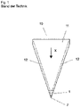
- FIG. 1 shows a former 10 as is known from the prior art.
- a former 10 includes a former plate 11, which is also referred to as a former plate.
- This funnel plate 11 essentially has the shape of a triangle, in particular an isosceles triangle, in particular when the funnel plate 11 also has the pointed tip of the funnel 7 forms.
- the so-called funnel legs 12 are attached to the two legs of the triangular funnel plate 11 and have a curved curvature, in particular a curvature in the shape of a cylinder jacket or a cone jacket.
- funnel legs 12 can be designed in the form of a bent metal sheet, in the simplest case these are the correspondingly curved edge areas of the funnel metal sheet 11. Frequently, however, the funnel legs 12 are also made of round material such as pipes or conically machined pipes, to which the funnel metal sheet 11 is attached.
- Such a former 10 is used to fold a substrate running over the former 10 in the transport direction X, which substrate is fundamentally both arc-shaped and, in particular, web-shaped.
- the substrate, not shown, that is guided over the former 10 in the transport direction X encloses the former legs 12 so that the former tip 7 forms a fold in the X transport direction.
- formers 10 Since high demands are placed on the former tip 7 in terms of geometry, and since the former tip 7 is subjected to relatively high wear, formers 10 often include a former nose 1, which is manufactured as a separate component and attached to the former 10 by means of a detachable and thus reversible connection are attached.
- the funnel nose 1 to be made from a different material than the funnel plate 11, the funnel tip 7 to be designed to have a geometry that is adapted to the substrate, and only the funnel tip 7 to be replaced in the event of excessive wear.
- FIG. 2 shows such a funnel nose 1 in a three-dimensional representation.
- the geometry of the funnel nose 1 shown is purely exemplary, since in particular the funnel tip 7 is designed depending on the substrate.
- the funnel nose 1 comprises a top surface 2 with two top surface edges 3 tapering to a point in the transport direction X, over which the substrate is transported in the area of a fold to be formed, and adjacent to each of the top surface edges 3 a curved side surface 4, with each side surface 4 having at least one Blown air duct 5 exits for outflow of blown air supplied under pressure, the blown air duct 5 having an exit surface 6 on the respective leg surface 4 .
- at least one exit surface 6 has a first extent a and a second extent b, with the first extent a being greater than the second extent b.
- the funnel nose 1 In the exemplary embodiment of the funnel nose 1 shown, five blown air channels 5 with an exit surface 6 are shown on the curved leg surface 4, this number being merely an example.
- the number of blown air channels 5 for outflow of blown air can be chosen arbitrarily and depends in particular on the included angle ⁇ to the cover surface edge 3 and the length ratio, ie the ratio of the first extension a to the second extension b.
- leg surface 4 which is arranged on the right-hand side, viewed in transport direction X, is shown, for the sake of completeness it is mentioned here that leg surface 4, which is arranged on the left-hand side viewed in transport direction X, also has at least one blast air channel 5 with an outlet surface formed on leg surface 4 6 has.
- the funnel nose 1 is symmetrical to a plane, not shown, that runs through the funnel tip 7 and is arranged perpendicularly to the top surface 2 .
- the blown air channels 5 Due to the ratio of the first extension a to the second extension b, the blown air channels 5 essentially have the shape of a slot.
- FIGS. 3 , 4 and 5 show different configurations of the exit surfaces 6 of section Y resulting from the blast air channels 5 on the side surfaces 4 2 on an enlarged scale.
- FIG 3 shows a rectangular exit surface 6 of the blown air channel 5 on the side surface 4, designed as an example as a development of the side surface 4, which has a first extent a and a second extent b.
- the first extension a is larger than the second extension b, so that the blown air channel 5 has the shape of a slot at least in the area of the leg surface 4 .
- the corners of the exit surface 6 can be rounded or sharp-edged.
- the edges with the first extension a and the edges of the second extension b are parallel in the example shown, depending on the radius of curvature of the side surface 4 deviations can also occur here, so that the opening surface can have a parallelogram-like shape.
- the edge of the first extension a encloses an angle ⁇ to the cover surface edge 3 .
- the 4 shows an exemplary configured exit surface 6 of the blown air channel 5 on the leg surface 4 in an elliptical shape, which has a first maximum extent a and a second maximum extent b.
- the first extension a is larger than the second extension b, so that the blown air channel 5 has the shape of a slot with an elliptical cross section at least in the area of the leg surface 4 .
- the first extent a encloses an angle ⁇ to the cover surface edge 3 .
- figure 5 shows an exemplary S-shaped exit surface 6 of the blown air channel 5 on the leg surface 4, which has a first extension a and a second extension b.
- the first extension a is larger than the second extension b, so that the blown air channel 5 has the shape of an S-shaped slot at least in the area of the leg surface 4 .
- the corners of the exit surface 6 can be rounded or sharp-edged.
- the edge of the first extension a encloses an angle ⁇ to the cover surface edge 3 .
- the angle between an edge of the first extension a and thus the first extension a can be arranged perpendicularly to the adjacent cover surface edge 3 .
- the angle ⁇ is 90°.
- the angle ⁇ between an edge of the first extension a and thus the angle ⁇ between the first extension a perpendicular and the adjacent top surface edge 3 can be zero, so that in this case, which is not shown in the drawing, an edge of the first extension a and/or the first extension a parallel to the adjacent cover surface edge 3.
- the first extent a encloses an angle ⁇ in a range from 15° to 75°, in particular in a range from 30° to 60° to the adjacent cover surface edge 3 .
- the angle ⁇ can be defined either in a plane spanned by the exit surface 6 or on the development of the curved side surface 4, since the differences in practice are only extremely small.
- the blower air ducts 5 shown, with exit surfaces 6 resulting from the leg surfaces 4, have a width and thus a second extent b, which is in a range from 0.5 millimeters to 5 millimeters.
- the second extension b is in a range from 0.8 millimeters to 1.5 millimeters.
- the second extent b is essentially the same over the length and thus over the first extent a, in the case of exit surfaces 6 with an essentially elliptical cross-section, such as in FIG 4 shown, the largest second extension b, which is essentially perpendicular to the first extension a, is used for this.
- the largest respective value is used both for the first extension a and for the second extension.
- a larger value for the second extension can also be used for funnel noses 1 with very large dimensions, but this must not assume or exceed a value by which the shape of the curved leg surface 4 is impermissibly severely impaired in the sense of being deformed.
- the exit surface 6 depicted by an exit channel 5 on the leg surface 4 has a length which is defined by the ratio of the first extent a to the second extent and is in a range from 1.5 to 15, in particular in a range from 2 to 10 .
- the exit surface 6 has at least one web 8 over the first extent a.
- This web 8 protrudes into the blown air opening 5 and terminates on the outside with the side surface 4 .
- These webs 8 are preferably used when the ratio of the first extension a to the second extension b is greater than or equal to 4.
- An exit surface 6 provided with a web 8 is shown in FIG 6 shown.
- the width of the web 8 is preferably in a range of 1 to 3 millimeters.
- a plurality of blast air ducts 5 and thus exit surfaces 6 can be arranged on one leg surface 4 . If a plurality of exit surfaces 6 are present on a leg surface 4, the exit surfaces 6 are at a distance of 3 to 30 millimeters from one another, it also being possible for this distance to be increased. However, it should be noted here that a smaller distance between the exit surfaces 6 is advantageous since a more uniform air cushion can thus be achieved between the substrate and the leg surface 4 and between the substrate and the top surface 2 .
- exit surfaces 6 can extend both in the extent of the top surface edge 3 and essentially perpendicularly and/or in the direction of the first extension a and /or be arranged correspondingly spaced apart from one another in the direction of the second extension b.
- exit surfaces 6 can in principle assume any round or polygonal shape such as, for example, triangles, pentagons or the like.
- the configuration in which the first extent a is greater than the second extent b is particularly preferred.
- a plurality of exit surfaces 6 can also be arranged on one side surface 4, which differ with regard to at least one extension a or b and/or differ from one another with regard to the shape of the exit surface 6 and/or have different distances from one another with regard to the distance from the cover surface edge 3 and/or from one another.
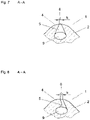
- FIG. 7 shows a schematic representation of the view of the section AA from 3 .
- This figure shows a detail of a section through the funnel nose 1 in the area of a blown air duct 5.
- the blown air can be supplied to the at least one blown air duct 5 of a side surface 4 via an air supply bore 9 integrated in the funnel nose 1 and flows via the air supply bore 9 into the at least one blown air duct 5.
- the blown air channel 5 exits at the leg surface 4 and forms the exit surface 6 there, through which the supplied blown air can exit in order to form an air cushion between the outer surfaces of the funnel nose 1 and the substrate, not shown.
- the blown air channel 5 has a cross-sectional area or a cross section which is larger than the area of the exit surface 6 resulting on the side surface 4 .
- This can be brought about by the blower air duct 5 at least partially having an essentially conical or pyramidal or truncated pyramid shape, so that the cross section increases with increasing distance from the side surface 4 .
- Such a configuration is advantageous in that, on the one hand, the side surface 4 is only slightly interrupted by a small second extension b, and the flow speeds can be reduced and preferably kept in the range of a laminar flow due to the larger cross section of the blown air channel 5 inside the funnel nose 1 , in order to minimize the flow losses.
- FIG. 8 shows a further exemplary embodiment of a blown air channel 5 in which the walls exit at an angle to the side surface 4 .
- the walls of at least one blast air duct 5 can be designed spatially and thus also in their orientation such that both the exit angle and the exit direction can be adjusted according to the geometric and flow conditions in such a way that the blown air exiting from the blown air channel 5, for example in or counter to the transport direction X or at any angle thereto from the exit surface 6.
- the funnel nose 1 is made, for example, from a nickel-based alloy, from a tool steel or from a martensitic steel or from a ceramic material or from an arrangement of different materials. In addition, it is possible to coat the funnel nose 1 with appropriate friction-reducing and/or wear-resistant coatings.
- the funnel nose 1 is preferably manufactured using an additive manufacturing process, which is known as 3D printing, since this manufacturing process can be used to produce almost any geometry and offers a large variety of different materials.
Landscapes
- Engineering & Computer Science (AREA)
- Mechanical Engineering (AREA)
- Folding Of Thin Sheet-Like Materials, Special Discharging Devices, And Others (AREA)
Applications Claiming Priority (1)
| Application Number | Priority Date | Filing Date | Title |
|---|---|---|---|
| DE102021103766.2A DE102021103766A1 (de) | 2021-02-17 | 2021-02-17 | Trichternase und Falztrichter |
Publications (2)
| Publication Number | Publication Date |
|---|---|
| EP4046799A1 true EP4046799A1 (fr) | 2022-08-24 |
| EP4046799B1 EP4046799B1 (fr) | 2025-09-10 |
Family
ID=80445525
Family Applications (1)
| Application Number | Title | Priority Date | Filing Date |
|---|---|---|---|
| EP22155341.5A Active EP4046799B1 (fr) | 2021-02-17 | 2022-02-07 | Bec de triangle de pliage et triangle de pliage |
Country Status (2)
| Country | Link |
|---|---|
| EP (1) | EP4046799B1 (fr) |
| DE (1) | DE102021103766A1 (fr) |
Citations (5)
| Publication number | Priority date | Publication date | Assignee | Title |
|---|---|---|---|---|
| DE1142878B (de) * | 1961-01-28 | 1963-01-31 | Maschf Augsburg Nuernberg Ag | Falztrichter zum Laengsfalzen von in Rotationsdruckmaschinen verarbeiteten Papierbahnen |
| US4321051A (en) * | 1979-05-29 | 1982-03-23 | M.A.N.-Roland Druckmaschinen Aktiengesellschaft | Method of making a folding former |
| DE4435528A1 (de) | 1994-10-05 | 1996-04-18 | Roland Man Druckmasch | Falztrichter für eine Druckmaschine |
| EP0945385A2 (fr) | 1998-03-26 | 1999-09-29 | Heidelberger Druckmaschinen Aktiengesellschaft | Triangle plieur d'un appareil de pliage d'une machine d'impression rotative |
| DE10031814A1 (de) | 2000-06-30 | 2002-01-10 | Heidelberger Druckmasch Ag | Einrichtung zum berührungsfreien Führen eines Bahnmaterials über eine Fläche |
Family Cites Families (2)
| Publication number | Priority date | Publication date | Assignee | Title |
|---|---|---|---|---|
| ATE390280T1 (de) | 2002-10-19 | 2008-04-15 | Koenig & Bauer Ag | Leitelemente einer druckeinheit |
| DE102005001518A1 (de) | 2004-04-27 | 2005-11-24 | Bach Maschinenbau Gmbh | Trichterspitze und damit ausgestattete Falzeinrichtung zum Falzen von Materialbahnen |
-
2021
- 2021-02-17 DE DE102021103766.2A patent/DE102021103766A1/de active Pending
-
2022
- 2022-02-07 EP EP22155341.5A patent/EP4046799B1/fr active Active
Patent Citations (6)
| Publication number | Priority date | Publication date | Assignee | Title |
|---|---|---|---|---|
| DE1142878B (de) * | 1961-01-28 | 1963-01-31 | Maschf Augsburg Nuernberg Ag | Falztrichter zum Laengsfalzen von in Rotationsdruckmaschinen verarbeiteten Papierbahnen |
| US4321051A (en) * | 1979-05-29 | 1982-03-23 | M.A.N.-Roland Druckmaschinen Aktiengesellschaft | Method of making a folding former |
| DE4435528A1 (de) | 1994-10-05 | 1996-04-18 | Roland Man Druckmasch | Falztrichter für eine Druckmaschine |
| US5779616A (en) * | 1994-10-05 | 1998-07-14 | Man Roland Druckmaschinen Ag | Former for a printing machine |
| EP0945385A2 (fr) | 1998-03-26 | 1999-09-29 | Heidelberger Druckmaschinen Aktiengesellschaft | Triangle plieur d'un appareil de pliage d'une machine d'impression rotative |
| DE10031814A1 (de) | 2000-06-30 | 2002-01-10 | Heidelberger Druckmasch Ag | Einrichtung zum berührungsfreien Führen eines Bahnmaterials über eine Fläche |
Also Published As
| Publication number | Publication date |
|---|---|
| DE102021103766A1 (de) | 2022-08-18 |
| EP4046799B1 (fr) | 2025-09-10 |
Similar Documents
| Publication | Publication Date | Title |
|---|---|---|
| EP0427015B1 (fr) | Dispositif pour le guidage flottant de bandes ou feuilles de matériaux | |
| EP1554208B1 (fr) | Cone plieur pour machine de production ou de traitement de bandes de matiere | |
| DE19631598C2 (de) | Pneumatische Bogenführungsvorrichtung in einer Druckmaschine | |
| WO1997006087A1 (fr) | Dispositif de guidage pour feuille venant d'etre imprimee | |
| EP3140056B1 (fr) | Déflecteur de bande et ensemble de cylindre | |
| EP0406529B1 (fr) | Dispositif d'enduction | |
| EP0855464A2 (fr) | Dispositif et méthode d'enduction directe ou indirecte d'une substance liquide ou pâteuse ssur une bande en mouvement | |
| EP4046799B1 (fr) | Bec de triangle de pliage et triangle de pliage | |
| DE4014780C2 (de) | Bogenleiteinrichtung | |
| EP3243779B1 (fr) | Bande de transport pour feuilles d'impression | |
| DE202021100783U1 (de) | Trichternase und Falztrichter | |
| DE102009060276A1 (de) | Vorrichtung zum Wenden von bahnförmigen Substraten | |
| DE10323468A1 (de) | Bogen verarbeitende Maschine mit einer pneumatischen Bogenleitvorrichtung | |
| DE2024624C3 (de) | Vorrichtung zur Führung einer vorgefalteten Endlosbahn | |
| DE2822137C2 (de) | Maschine zur Verarbeitung bahnförmigen Materials | |
| EP4007659B1 (fr) | Buse | |
| WO2005105334A1 (fr) | Dispositif pour refroidir des toles et des feuillards | |
| EP4177194B1 (fr) | Dispositif d'épandage | |
| EP2141101A2 (fr) | Dispositif d'aspiration de tableau en tôle et dispositif de transport de tableaux en tôle dans une machine d'impression de tôle ou une machine de laquage de tôle | |
| DE8915626U1 (de) | Vorrichtung zum schwebenden Führen von zu fördernden Materialbahnen oder Materialbogen | |
| DE29720989U1 (de) | Bogenführungseinrichtung mit einer Leitfläche in einer Druckmaschine | |
| DE20303720U1 (de) | Bahnführung in einer Rollenrotatinsdruckmaschine | |
| DE102021103975B4 (de) | Bearbeitungsmaschine mit zumindest einer digitalen Druckeinheit und mit zumindest einem Saugtransportmittel | |
| DE60002620T2 (de) | Flexodruckmaschine und Flexodruckverfahren | |
| DE102023109230A1 (de) | Vorrichtung und Verfahren zur Schlauchbildung |
Legal Events
| Date | Code | Title | Description |
|---|---|---|---|
| PUAI | Public reference made under article 153(3) epc to a published international application that has entered the european phase |
Free format text: ORIGINAL CODE: 0009012 |
|
| STAA | Information on the status of an ep patent application or granted ep patent |
Free format text: STATUS: THE APPLICATION HAS BEEN PUBLISHED |
|
| AK | Designated contracting states |
Kind code of ref document: A1 Designated state(s): AL AT BE BG CH CY CZ DE DK EE ES FI FR GB GR HR HU IE IS IT LI LT LU LV MC MK MT NL NO PL PT RO RS SE SI SK SM TR |
|
| STAA | Information on the status of an ep patent application or granted ep patent |
Free format text: STATUS: REQUEST FOR EXAMINATION WAS MADE |
|
| 17P | Request for examination filed |
Effective date: 20230215 |
|
| RBV | Designated contracting states (corrected) |
Designated state(s): AL AT BE BG CH CY CZ DE DK EE ES FI FR GB GR HR HU IE IS IT LI LT LU LV MC MK MT NL NO PL PT RO RS SE SI SK SM TR |
|
| GRAP | Despatch of communication of intention to grant a patent |
Free format text: ORIGINAL CODE: EPIDOSNIGR1 |
|
| STAA | Information on the status of an ep patent application or granted ep patent |
Free format text: STATUS: GRANT OF PATENT IS INTENDED |
|
| INTG | Intention to grant announced |
Effective date: 20250617 |
|
| GRAS | Grant fee paid |
Free format text: ORIGINAL CODE: EPIDOSNIGR3 |
|
| GRAA | (expected) grant |
Free format text: ORIGINAL CODE: 0009210 |
|
| STAA | Information on the status of an ep patent application or granted ep patent |
Free format text: STATUS: THE PATENT HAS BEEN GRANTED |
|
| AK | Designated contracting states |
Kind code of ref document: B1 Designated state(s): AL AT BE BG CH CY CZ DE DK EE ES FI FR GB GR HR HU IE IS IT LI LT LU LV MC MK MT NL NO PL PT RO RS SE SI SK SM TR |
|
| REG | Reference to a national code |
Ref country code: GB Ref legal event code: FG4D Free format text: NOT ENGLISH |
|
| REG | Reference to a national code |
Ref country code: CH Ref legal event code: EP |
|
| REG | Reference to a national code |
Ref country code: DE Ref legal event code: R096 Ref document number: 502022005369 Country of ref document: DE |
|
| REG | Reference to a national code |
Ref country code: IE Ref legal event code: FG4D Free format text: LANGUAGE OF EP DOCUMENT: GERMAN |
|
| PG25 | Lapsed in a contracting state [announced via postgrant information from national office to epo] |
Ref country code: NO Free format text: LAPSE BECAUSE OF FAILURE TO SUBMIT A TRANSLATION OF THE DESCRIPTION OR TO PAY THE FEE WITHIN THE PRESCRIBED TIME-LIMIT Effective date: 20251210 |
|
| REG | Reference to a national code |
Ref country code: LT Ref legal event code: MG9D |
|
| PG25 | Lapsed in a contracting state [announced via postgrant information from national office to epo] |
Ref country code: FI Free format text: LAPSE BECAUSE OF FAILURE TO SUBMIT A TRANSLATION OF THE DESCRIPTION OR TO PAY THE FEE WITHIN THE PRESCRIBED TIME-LIMIT Effective date: 20250910 |
|
| REG | Reference to a national code |
Ref country code: NL Ref legal event code: MP Effective date: 20250910 |
|
| PG25 | Lapsed in a contracting state [announced via postgrant information from national office to epo] |
Ref country code: HR Free format text: LAPSE BECAUSE OF FAILURE TO SUBMIT A TRANSLATION OF THE DESCRIPTION OR TO PAY THE FEE WITHIN THE PRESCRIBED TIME-LIMIT Effective date: 20250910 |
|
| PG25 | Lapsed in a contracting state [announced via postgrant information from national office to epo] |
Ref country code: GR Free format text: LAPSE BECAUSE OF FAILURE TO SUBMIT A TRANSLATION OF THE DESCRIPTION OR TO PAY THE FEE WITHIN THE PRESCRIBED TIME-LIMIT Effective date: 20251211 |
|
| PG25 | Lapsed in a contracting state [announced via postgrant information from national office to epo] |
Ref country code: SE Free format text: LAPSE BECAUSE OF FAILURE TO SUBMIT A TRANSLATION OF THE DESCRIPTION OR TO PAY THE FEE WITHIN THE PRESCRIBED TIME-LIMIT Effective date: 20250910 |
|
| PG25 | Lapsed in a contracting state [announced via postgrant information from national office to epo] |
Ref country code: LV Free format text: LAPSE BECAUSE OF FAILURE TO SUBMIT A TRANSLATION OF THE DESCRIPTION OR TO PAY THE FEE WITHIN THE PRESCRIBED TIME-LIMIT Effective date: 20250910 |
|
| PG25 | Lapsed in a contracting state [announced via postgrant information from national office to epo] |
Ref country code: BG Free format text: LAPSE BECAUSE OF FAILURE TO SUBMIT A TRANSLATION OF THE DESCRIPTION OR TO PAY THE FEE WITHIN THE PRESCRIBED TIME-LIMIT Effective date: 20250910 Ref country code: PL Free format text: LAPSE BECAUSE OF FAILURE TO SUBMIT A TRANSLATION OF THE DESCRIPTION OR TO PAY THE FEE WITHIN THE PRESCRIBED TIME-LIMIT Effective date: 20250910 |
|
| PG25 | Lapsed in a contracting state [announced via postgrant information from national office to epo] |
Ref country code: RS Free format text: LAPSE BECAUSE OF FAILURE TO SUBMIT A TRANSLATION OF THE DESCRIPTION OR TO PAY THE FEE WITHIN THE PRESCRIBED TIME-LIMIT Effective date: 20251210 |
|
| PG25 | Lapsed in a contracting state [announced via postgrant information from national office to epo] |
Ref country code: ES Free format text: LAPSE BECAUSE OF FAILURE TO SUBMIT A TRANSLATION OF THE DESCRIPTION OR TO PAY THE FEE WITHIN THE PRESCRIBED TIME-LIMIT Effective date: 20250910 |
|
| PG25 | Lapsed in a contracting state [announced via postgrant information from national office to epo] |
Ref country code: NL Free format text: LAPSE BECAUSE OF FAILURE TO SUBMIT A TRANSLATION OF THE DESCRIPTION OR TO PAY THE FEE WITHIN THE PRESCRIBED TIME-LIMIT Effective date: 20250910 |
|
| PG25 | Lapsed in a contracting state [announced via postgrant information from national office to epo] |
Ref country code: SM Free format text: LAPSE BECAUSE OF FAILURE TO SUBMIT A TRANSLATION OF THE DESCRIPTION OR TO PAY THE FEE WITHIN THE PRESCRIBED TIME-LIMIT Effective date: 20250910 |
|
| PGFP | Annual fee paid to national office [announced via postgrant information from national office to epo] |
Ref country code: DE Payment date: 20260218 Year of fee payment: 5 |
|
| PGFP | Annual fee paid to national office [announced via postgrant information from national office to epo] |
Ref country code: AT Payment date: 20260301 Year of fee payment: 5 |
|
| PG25 | Lapsed in a contracting state [announced via postgrant information from national office to epo] |
Ref country code: IT Free format text: LAPSE BECAUSE OF FAILURE TO SUBMIT A TRANSLATION OF THE DESCRIPTION OR TO PAY THE FEE WITHIN THE PRESCRIBED TIME-LIMIT Effective date: 20250910 |
|
| PG25 | Lapsed in a contracting state [announced via postgrant information from national office to epo] |
Ref country code: IS Free format text: LAPSE BECAUSE OF FAILURE TO SUBMIT A TRANSLATION OF THE DESCRIPTION OR TO PAY THE FEE WITHIN THE PRESCRIBED TIME-LIMIT Effective date: 20260110 |
|
| PG25 | Lapsed in a contracting state [announced via postgrant information from national office to epo] |
Ref country code: CZ Free format text: LAPSE BECAUSE OF FAILURE TO SUBMIT A TRANSLATION OF THE DESCRIPTION OR TO PAY THE FEE WITHIN THE PRESCRIBED TIME-LIMIT Effective date: 20250910 Ref country code: PT Free format text: LAPSE BECAUSE OF FAILURE TO SUBMIT A TRANSLATION OF THE DESCRIPTION OR TO PAY THE FEE WITHIN THE PRESCRIBED TIME-LIMIT Effective date: 20260112 |
|
| PG25 | Lapsed in a contracting state [announced via postgrant information from national office to epo] |
Ref country code: SK Free format text: LAPSE BECAUSE OF FAILURE TO SUBMIT A TRANSLATION OF THE DESCRIPTION OR TO PAY THE FEE WITHIN THE PRESCRIBED TIME-LIMIT Effective date: 20250910 Ref country code: EE Free format text: LAPSE BECAUSE OF FAILURE TO SUBMIT A TRANSLATION OF THE DESCRIPTION OR TO PAY THE FEE WITHIN THE PRESCRIBED TIME-LIMIT Effective date: 20250910 |