EP4046926B1 - Dispositif de remplissage de matières en vrac d'un récipient dans un sac de récipient - Google Patents
Dispositif de remplissage de matières en vrac d'un récipient dans un sac de récipient Download PDFInfo
- Publication number
- EP4046926B1 EP4046926B1 EP21401005.0A EP21401005A EP4046926B1 EP 4046926 B1 EP4046926 B1 EP 4046926B1 EP 21401005 A EP21401005 A EP 21401005A EP 4046926 B1 EP4046926 B1 EP 4046926B1
- Authority
- EP
- European Patent Office
- Prior art keywords
- seal
- container
- container bag
- seals
- housing
- Prior art date
- Legal status (The legal status is an assumption and is not a legal conclusion. Google has not performed a legal analysis and makes no representation as to the accuracy of the status listed.)
- Active
Links
Images













Classifications
-
- B—PERFORMING OPERATIONS; TRANSPORTING
- B65—CONVEYING; PACKING; STORING; HANDLING THIN OR FILAMENTARY MATERIAL
- B65B—MACHINES, APPARATUS OR DEVICES FOR, OR METHODS OF, PACKAGING ARTICLES OR MATERIALS; UNPACKING
- B65B69/00—Unpacking of articles or materials, not otherwise provided for
- B65B69/0008—Opening and emptying bags
-
- B—PERFORMING OPERATIONS; TRANSPORTING
- B65—CONVEYING; PACKING; STORING; HANDLING THIN OR FILAMENTARY MATERIAL
- B65B—MACHINES, APPARATUS OR DEVICES FOR, OR METHODS OF, PACKAGING ARTICLES OR MATERIALS; UNPACKING
- B65B69/00—Unpacking of articles or materials, not otherwise provided for
- B65B69/0075—Emptying systems for flexible intermediate bulk containers [FIBC]
-
- B—PERFORMING OPERATIONS; TRANSPORTING
- B65—CONVEYING; PACKING; STORING; HANDLING THIN OR FILAMENTARY MATERIAL
- B65G—TRANSPORT OR STORAGE DEVICES, e.g. CONVEYORS FOR LOADING OR TIPPING, SHOP CONVEYOR SYSTEMS OR PNEUMATIC TUBE CONVEYORS
- B65G69/00—Auxiliary measures taken, or devices used, in connection with loading or unloading
- B65G69/18—Preventing escape of dust
- B65G69/181—Preventing escape of dust by means of sealed systems
- B65G69/183—Preventing escape of dust by means of sealed systems with co-operating closure members on each of the parts of a separable transfer channel
Definitions
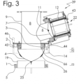
- the web arranged on the adjustable and/or automatically lowerable lid which is oriented upwards with respect to the container, with the first seal connected to it, is pushed in between the second and third seals from below and the end of the tubular container bag is guided around the web and rests or can be placed against the seal connected to the fixed housing and the seal.
- the web is designed as an annular web which is connected to the adjustable cover or an annular body which is designed as a flat or thin annular structure.
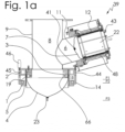
- the tubular container bag 4 is created by tying off its lower end with the aid of a closure element 23.
- the outer or first seal 1, the middle or second seal 2 and the inner or third seal 3 can be activated using compressed air via a compressed air system not shown in the drawing. All seals 1-3 are arranged at a different height.
- the second seal 2 is connected to the fixed housing 8 or to an outer housing part 14 arranged on the housing 8 of the device 39.
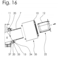
- the nozzle closure 22 with the compressed air connection 43 is connected to the compressed air channel 44 (7b), which can be activated by a compressed air system not shown in the drawing and which initiates the sealing process of the film tube 7.
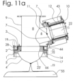
- the nozzle closure 22 has a cover 25' having a handle 24, with the aid of which the nozzle closure 22 can be moved or held and inserted into or removed from the tubular outlet nozzle, as described below.
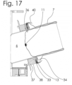
- the wall of the housing part 32 of the nozzle closure 22 is provided with numerous holes 63 through which compressed air can pass, so that the Seal 12 can expand and rest against an inner wall 41 of the outlet nozzle 6, thereby increasing the sealing effect. With the help of seal 12, film tube 7 is sealed in outlet nozzle 6.
- the wall of the housing part 32 of the nozzle closure 22 is provided with numerous holes 63 through which compressed air can pass, so that the seal 12 can expand and rest against an inner wall 41 of the outlet nozzle 6, thus increasing the sealing effect.
- the film tube 7 is sealed in the outlet nozzle 6 with the help of the seal 12.
- the wall of the housing part 32 of the nozzle closure 22 is provided with numerous holes 63 through which compressed air can pass, so that the seal 12 can expand and rest against an inner wall 41 of the outlet nozzle 6, thus increasing the sealing effect.
- the film tube 7 is sealed in the outlet nozzle 6 with the aid of the seal 12.
- a piece of the film tube 7 is used during each filling process, which is folded axially and meanderingly and applied to the outlet nozzle 6 so that a length of several meters can be achieved.
- the amount consumed during a filling process is, for example, 0.4 m, so that with a total length of the film tube of 7.2 m, approximately 18 fillings are possible.
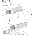
- a new film tube 7' is put over the rest of the film tube 7 and pulled onto the nozzle shoulder 37, whereby the end of the new film tube 7 is closed with the closure 11'.
- Fig. 19a shows, the new film tube 7' is fixed and sealed on the nozzle shoulder 37 with the aid of a clamping element 20.
- the end of the film tube 7' is clamped in the clamping element 20.
- the tensioning element 20 consists of a metal band 70 with a hook 71 in which a toggle lever closure 72 engages and is tensioned so that the film tube 7' is clamped and sealed with the aid of the tensioning element 20.
- a C-shaped profile seal 61 with the embedded metal band 70 serves to reinforce a groove 38.
- the diameter of the tensioning element 20, which is designed as a tensioning ring, can be changed with the aid of a tensioning device 84, which has a worm thread with an adjusting screw, the diameter of the tensioning ring and the contact pressure on the outlet nozzle 6 can be increased or decreased when the adjusting screw is actuated for this purpose.
- Fig. 21 the film tube 7 is completely received in the film tube 7' and tied off with two closures 11' and 11". Now the end of the film tube 7' lying outside the outlet nozzle 6 with the previous film tube 7 enclosed therein between the two closures 11' can be separated from the part of the film tube 7' remaining in the outlet nozzle 6 and disposed of.
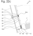
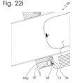
- FIG. 22c which is shown in an enlarged view of the Figure 22a is shown, another clamping and sealing device 75 is shown.
- the movable ring 33 (22b) is pulled against the counterholder 34 with the aid of several magnets 56a.
- several threaded spindles 51 are firmly connected to the movable ring 33.
- the threaded spindles 51 extend through holes 82 in the nozzle shoulder 37 and protrude on a rear surface 83 of the nozzle shoulder 37 so that a threaded nut 50 can be screwed onto the free end of the threaded spindle 51.
- the movable ring 33 is removed from the magnets 56a so that the film tube 7' can be inserted into the groove 36 or led out of the groove 36.
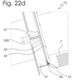
- a pneumatic or electric cylinder 56b By means of a pneumatic or electric cylinder 56b ( Fig. 22d ) the lifting movement of the movable ring 33 is generated by means of a piston rod 57, which is connected at one end to the movable ring 33 and at the other end to the pneumatic or electric cylinder. With the help of the lifting movement of the piston rod 57, the movable ring 33 can be adjusted and thus the groove 36 can be opened or closed.
- Fig. 22e has a clamping and sealing device 77 for adjusting a rack 58, which opens or closes the groove 36 with the aid of a rack gear 56c.
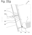
- a clamping and sealing device 78 has a toggle lever clamp 56d as an adjusting device, which is connected to the movable ring 33 via an extension rod 59 and in this way enables an adjustment of the movable ring 33.
- the new film tube 7' is placed on the outlet nozzle 6 and the nozzle shoulder 37.
- the housing 35 can first be mounted on the nozzle shoulder 37 and then the nozzle closure 22 can be inserted back into the outlet nozzle 6.
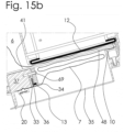
- the seal 10 and the seal 12 are activated to seal the film tube 7' to seal it so that as little dust as possible can get into the film tube.
Landscapes
- Engineering & Computer Science (AREA)
- Mechanical Engineering (AREA)
- Basic Packing Technique (AREA)
Claims (11)
- Dispositif (39) pour le remplissage de matières en vrac à partir d'un récipient ou d'un boîtier (8) dans un sac récipient (4) en forme de tuyau, qui est raccordé au boîtier de réception (8) et dont l'extrémité supérieure peut être fermée, tandis que la deuxième extrémité ou l'extrémité inférieure du sac récipient (4) peut être fermée à l'aide d'au moins trois bagues d'étanchéité (1, 2, 3) du dispositif (39) agencées coaxialement par rapport à un axe médian du boîtier (8), de telle sorte que notamment même de très petites particules ne soient pas libérées vers l'extérieur dans l'air ambiant,le dispositif (39) présentant les caractéristiques suivantes :a) les bagues d'étanchéité (1, 2, 3) individuelles pouvant être soumises à une pression sont agencées de manière décalée les unes par rapport aux autres par rapport à l'axe médian longitudinal d'un dispositif (39) pour le remplissage de matières en vrac ;b) le récipient (8) du dispositif (39) présente dans la zone de son extrémité inférieure un couvercle (5) mobile vers le haut et vers le bas ;c) le premier joint d'étanchéité (1) est agencé de manière fixe sur le couvercle mobile (5) et peut être déplacé vers le haut et vers le bas conjointement avec le couvercle mobile (5) ;d) le deuxième joint d'étanchéité (2) est agencé sur le boîtier fixe (8) du dispositif (39) ;e) le troisième joint d'étanchéité (3) est agencé entre le premier et le deuxième joint d'étanchéité (1, 2) sur le boîtier fixe (8) du dispositif (39) ou sur une partie de boîtier (66) du dispositif (39) ;f) un espace intermédiaire formé entre deux joints d'étanchéité, pour la réception temporaire d'une partie du tuyau en film ou d'un sac récipient, est dirigé et/ou ouvert uniquement vers le bas par rapport à la surface de support du récipient,caractérisé en ce que, vu dans la direction de remplissage, la bague d'étanchéité inférieure ou première bague d'étanchéité (1) est raccordée au couvercle mobile ou corps annulaire (5), la deuxième bague d'étanchéité (2) étant agencée à distance de la première bague d'étanchéité (1) à peu près au même diamètre par rapport au plan transversal, et le diamètre extérieur du troisième joint d'étanchéité (3) formant avec le deuxième joint d'étanchéité (2) un espace intermédiaire ou une fente (28) par rapport à l'axe médian du dispositif (39), dans lequel une nervure (19) du dispositif (39), raccordée au corps annulaire (5), est insérée et étanchéifie le sac récipient (4) en forme de tuyau lorsque celui-ci est serré dans l'espace intermédiaire ou la fente (28).
- Dispositif selon la revendication 1, caractérisé en ce que la nervure (19) agencée sur le couvercle (5) déplaçable et/ou abaissable automatiquement, orientée vers le haut par rapport au récipient 8, est insérée par le bas avec le premier joint d'étanchéité (1) qui y est raccordé entre le deuxième et le troisième joint d'étanchéité (2, 3), et l'extrémité du sac récipient (4) en forme de tuyau est guidée autour de la nervure (19) et s'applique contre le joint d'étanchéité (2) et le joint d'étanchéité (3) raccordés au boîtier fixe (8).
- Dispositif selon la revendication 1 ou 2, caractérisé en ce que, pour le transvasement de la matière en vrac, le couvercle mobile (5) est abaissé de la partie inférieure du boîtier (8) et sert à recevoir un autre sac récipient (4') en forme de tuyau dont l'extrémité est placée autour de la nervure (19) et du premier joint d'étanchéité (1).
- Dispositif selon la revendication 1 ou 2, caractérisé en ce que l'autre ou le deuxième sac récipient (4') peut être raccordé à l'aide du couvercle (5) à une tubulure ou à une pièce de raccordement (14) fixée au boîtier (8) et en ce que l'extrémité du deuxième sac récipient (4') est guidée autour de la nervure (19), qui est insérée vers le haut dans l'espace intermédiaire ou la fente (28) entre le deuxième joint d'étanchéité (3) et le troisième joint d'étanchéité (2) et qui étanchéifie le sac récipient (4) en forme de tuyau, le premier joint d'étanchéité ou joint d'étanchéité extérieur (1) pouvant être activé par de l'air comprimé et le deuxième et le troisième joint d'étanchéité (2, 3) étant alimentés en air comprimé.
- Dispositif selon la revendication 1 ou 2, caractérisé en ce que le premier sac récipient (4) peut être enlevé par l'intermédiaire d'une tubulure de sortie (6) agencée latéralement sur le boîtier (8) et le deuxième sac récipient (4') est fermé par l'intermédiaire d'une fermeture (23) et peut être ouvert en l'enlevant, de telle sorte que la matière en vrac peut être transvasée dans un troisième sac récipient (55), qui est fermé à l'aide de la première fermeture ou fermeture supérieure et d'une deuxième fermeture ou fermeture inférieure (23).
- Dispositif selon la revendication 1 ou 2 caractérisé en ce qu'un canal d'air comprimé (45) relié au ou aux sacs récipients (4, 4', 55) est raccordé à une conduite d'air comprimé (44) ou aux joints d'étanchéité (1, 2, 3) pour mesurer l'étanchéité du sac récipient (4) ou des sacs récipients (4, 4', 55).
- Dispositif selon la revendication 1 ou 2, caractérisé en ce que la nervure est réalisée sous forme de nervure annulaire (19) qui est raccordée au couvercle déplaçable (5) ou à un corps annulaire qui est réalisé sous forme de corps annulaire plat ou mince.
- Dispositif selon la revendication 1 ou 7, caractérisé en ce que la nervure (19) ou le corps annulaire plat ou mince est orienté vers le haut ou en direction d'une ouverture d'entrée ou une ouverture d'entrée supérieure du récipient (8) par rapport à la surface de support du récipient (8) et s'étend approximativement parallèlement à un axe médian longitudinal (85) du récipient (8).
- Dispositif selon la revendication 1 ou 8, caractérisé en ce que la nervure (19) ou le corps annulaire plat ou mince est orienté coaxialement à l'axe médian longitudinal (85) du récipient (8).
- Dispositif selon la revendication 1 ou 9, caractérisé en ce que la nervure (19) ou le corps annulaire plat ou mince peut être déplacé avec le couvercle (5) vers le haut et vers le bas en direction de l'axe médian longitudinal et peut être inséré par le bas dans la fente (28) entre deux joints d'étanchéité (2, 3) ou extrait de celle-ci et sert à recevoir une partie d'un tuyau en film (7), et l'une des extrémités ou l'extrémité supérieure de la fente (82) peut être fermée à l'aide d'un joint d'étanchéité ou d'un composant ou élément d'étanchéité (87) raccordé à la partie de boîtier (14).
- Dispositif selon la revendication 1 ou 9, caractérisé en ce que la nervure (19) forme, en liaison avec les deux joints d'étanchéité (2, 3) et une partie du tuyau en film, un dispositif d'étanchéité à l'aide duquel le sac récipient (4) peut être sécurisé et/ou étanchéifié à l'aide d'un dispositif de réglage ou d'une installation pneumatique.
Priority Applications (1)
| Application Number | Priority Date | Filing Date | Title |
|---|---|---|---|
| EP21401005.0A EP4046926B1 (fr) | 2021-02-18 | 2021-02-18 | Dispositif de remplissage de matières en vrac d'un récipient dans un sac de récipient |
Applications Claiming Priority (1)
| Application Number | Priority Date | Filing Date | Title |
|---|---|---|---|
| EP21401005.0A EP4046926B1 (fr) | 2021-02-18 | 2021-02-18 | Dispositif de remplissage de matières en vrac d'un récipient dans un sac de récipient |
Publications (3)
| Publication Number | Publication Date |
|---|---|
| EP4046926A1 EP4046926A1 (fr) | 2022-08-24 |
| EP4046926C0 EP4046926C0 (fr) | 2024-07-03 |
| EP4046926B1 true EP4046926B1 (fr) | 2024-07-03 |
Family
ID=74874788
Family Applications (1)
| Application Number | Title | Priority Date | Filing Date |
|---|---|---|---|
| EP21401005.0A Active EP4046926B1 (fr) | 2021-02-18 | 2021-02-18 | Dispositif de remplissage de matières en vrac d'un récipient dans un sac de récipient |
Country Status (1)
| Country | Link |
|---|---|
| EP (1) | EP4046926B1 (fr) |
Families Citing this family (4)
| Publication number | Priority date | Publication date | Assignee | Title |
|---|---|---|---|---|
| CH721047A2 (de) * | 2023-08-22 | 2025-02-28 | Rubitec Ag | Halterungs-anordnung zum dichten haltern eines folienschlauches und umfüllvorrichtung umfassend die halterungs-anordnung |
| DE102023126090A1 (de) * | 2023-09-26 | 2025-03-27 | Emde Automation Gmbh | Vorrichtung und verfahren zum entleeren eines behälters mit einem liner |
| LU506775B1 (de) * | 2024-04-02 | 2025-10-02 | J Engelsmann Ag | Verfahren zum Entleeren von Schüttgütern aus einem ersten Behälter in einen zweiten Behälter mit einer Entleervorrichtung |
| EP4722113A1 (fr) * | 2024-10-04 | 2026-04-08 | Hecht Technologie GmbH | Dispositif de raccordement |
Family Cites Families (5)
| Publication number | Priority date | Publication date | Assignee | Title |
|---|---|---|---|---|
| EP1708941B1 (fr) | 2003-12-11 | 2008-02-20 | Hecht Anlagenbau GmbH | Procede pour vider et remplir sans contamination des contenants pour matieres en vrac |
| CH699603B1 (de) | 2008-09-30 | 2014-03-14 | Rubitec Ag | Verfahren und Vorrichtung zum Umfüllen von Füllgut aus einem ersten Behälter in einen zweiten Behälter. |
| CH708545A1 (de) * | 2013-09-02 | 2015-03-13 | Rubitec Ag | Verfahren zum Umfüllen von Prozessmaterial zwischen einem Behältnis und einem Vorratsgefäss und Vorrichtung dazu. |
| DK3718911T3 (da) * | 2019-04-05 | 2022-01-03 | Rubitec Ag | Omfyldningsindretning til kontamineringsbeskyttet overføring af procesmateriale, der kan flyde, mellem en første og en anden beholder |
| DE102019110413B3 (de) | 2019-04-18 | 2020-03-26 | J. Engelsmann Ag | Vorrichtung zum Entleeren von Schüttgütern aus einem Behälter in einen schlauchförmigen Behältersack |
-
2021
- 2021-02-18 EP EP21401005.0A patent/EP4046926B1/fr active Active
Also Published As
| Publication number | Publication date |
|---|---|
| EP4046926C0 (fr) | 2024-07-03 |
| EP4046926A1 (fr) | 2022-08-24 |
Similar Documents
| Publication | Publication Date | Title |
|---|---|---|
| EP4046926A1 (fr) | Dispositif de remplissage de matières en vrac d'un récipient dans un sac de récipient | |
| EP4046927B1 (fr) | Procédé pour vider un sac de conteneur | |
| DE3886769T2 (de) | Verpackungsvorrichtung für die Verwendung von schlauchförmigem Hüllenmaterial. | |
| DE102019110413B3 (de) | Vorrichtung zum Entleeren von Schüttgütern aus einem Behälter in einen schlauchförmigen Behältersack | |
| EP0962143B1 (fr) | Dispositif pour la fabrication de saucisses | |
| EP0582955B1 (fr) | Dispositif pour doser et remplir des produits liquides ou pâteux, spécialement pour remplir des produits sélectionnés, comme par exemple du yaourt aux fruits ou similaire, de préférence sur des machines aseptiques à plusieurs voies | |
| EP3041749A1 (fr) | Dispositif de transvasement de matière de processus entre un premier et un deuxième récipient et procédé correspondant | |
| DE69900524T2 (de) | Verpackungsmaschine mit verbesserter Befestigung der Formeinrichtung | |
| DE102019109648B4 (de) | Anschlussvorrichtung | |
| DE102007038974B4 (de) | Vorrichtung zum kontaminationsfreien Abfüllen von Fliess- und Schüttgütern | |
| EP3693333A1 (fr) | Dispositif de traitement d'un récipient | |
| EP3428080B1 (fr) | Dispositif de raccordement | |
| WO2013050968A1 (fr) | Procédé pour vider et remplir sans contamination un contenant | |
| AT5904U1 (de) | Deckelmagazin sowie deckelaufsetz- und verschliess-einrichtung | |
| EP3718912A1 (fr) | Dispositif de raccordement | |
| DE19932519C5 (de) | Vorrichtung zum Entleeren von Spraydosen | |
| DE3246089C2 (de) | Vorrichtung zum Befüllen von Säcken | |
| EP3957570B1 (fr) | Dispositif de remplissage et/ou de vidange d'un récipient | |
| DE69705674T2 (de) | Entlade-Verfahren für Schüttgut von Behältern | |
| DE19714507A1 (de) | Rohrpost-Förderanlage | |
| DE10025595A1 (de) | Andockvorrichtung zum staubfreien Anschließen des Auslaufes eines Big Bag | |
| WO2009144021A1 (fr) | Dispositif et procédé de déversement ou de soutirage sans contamination de matières en vrac | |
| DE102020127213A1 (de) | Vorrichtung zum Befüllen und/oder Entleeren eines Behälters | |
| DE3108173C2 (de) | Maschine zum aseptischen Abfüllen von Beuteln mit einer Flüssigkeit oder dergleichen | |
| DE3928452C2 (fr) |
Legal Events
| Date | Code | Title | Description |
|---|---|---|---|
| PUAI | Public reference made under article 153(3) epc to a published international application that has entered the european phase |
Free format text: ORIGINAL CODE: 0009012 |
|
| STAA | Information on the status of an ep patent application or granted ep patent |
Free format text: STATUS: REQUEST FOR EXAMINATION WAS MADE |
|
| 17P | Request for examination filed |
Effective date: 20220120 |
|
| AK | Designated contracting states |
Kind code of ref document: A1 Designated state(s): AL AT BE BG CH CY CZ DE DK EE ES FI FR GB GR HR HU IE IS IT LI LT LU LV MC MK MT NL NO PL PT RO RS SE SI SK SM TR |
|
| STAA | Information on the status of an ep patent application or granted ep patent |
Free format text: STATUS: EXAMINATION IS IN PROGRESS |
|
| 17Q | First examination report despatched |
Effective date: 20230330 |
|
| GRAP | Despatch of communication of intention to grant a patent |
Free format text: ORIGINAL CODE: EPIDOSNIGR1 |
|
| STAA | Information on the status of an ep patent application or granted ep patent |
Free format text: STATUS: GRANT OF PATENT IS INTENDED |
|
| INTG | Intention to grant announced |
Effective date: 20240227 |
|
| RIN1 | Information on inventor provided before grant (corrected) |
Inventor name: KRETZAU, CHRISTIAN Inventor name: LIEDTKE, JOACHIM Inventor name: QUINDT, VIKTOR |
|
| GRAS | Grant fee paid |
Free format text: ORIGINAL CODE: EPIDOSNIGR3 |
|
| GRAA | (expected) grant |
Free format text: ORIGINAL CODE: 0009210 |
|
| STAA | Information on the status of an ep patent application or granted ep patent |
Free format text: STATUS: THE PATENT HAS BEEN GRANTED |
|
| AK | Designated contracting states |
Kind code of ref document: B1 Designated state(s): AL AT BE BG CH CY CZ DE DK EE ES FI FR GB GR HR HU IE IS IT LI LT LU LV MC MK MT NL NO PL PT RO RS SE SI SK SM TR |
|
| REG | Reference to a national code |
Ref country code: CH Ref legal event code: EP |
|
| REG | Reference to a national code |
Ref country code: DE Ref legal event code: R096 Ref document number: 502021004215 Country of ref document: DE |
|
| U01 | Request for unitary effect filed |
Effective date: 20240731 |
|
| U07 | Unitary effect registered |
Designated state(s): AT BE BG DE DK EE FI FR IT LT LU LV MT NL PT SE SI Effective date: 20240813 |
|
| PG25 | Lapsed in a contracting state [announced via postgrant information from national office to epo] |
Ref country code: NO Free format text: LAPSE BECAUSE OF FAILURE TO SUBMIT A TRANSLATION OF THE DESCRIPTION OR TO PAY THE FEE WITHIN THE PRESCRIBED TIME-LIMIT Effective date: 20241003 |
|
| PG25 | Lapsed in a contracting state [announced via postgrant information from national office to epo] |
Ref country code: PL Free format text: LAPSE BECAUSE OF FAILURE TO SUBMIT A TRANSLATION OF THE DESCRIPTION OR TO PAY THE FEE WITHIN THE PRESCRIBED TIME-LIMIT Effective date: 20240703 Ref country code: GR Free format text: LAPSE BECAUSE OF FAILURE TO SUBMIT A TRANSLATION OF THE DESCRIPTION OR TO PAY THE FEE WITHIN THE PRESCRIBED TIME-LIMIT Effective date: 20241004 |
|
| U20 | Renewal fee for the european patent with unitary effect paid |
Year of fee payment: 5 Effective date: 20241213 |
|
| PG25 | Lapsed in a contracting state [announced via postgrant information from national office to epo] |
Ref country code: IS Free format text: LAPSE BECAUSE OF FAILURE TO SUBMIT A TRANSLATION OF THE DESCRIPTION OR TO PAY THE FEE WITHIN THE PRESCRIBED TIME-LIMIT Effective date: 20241103 |
|
| PG25 | Lapsed in a contracting state [announced via postgrant information from national office to epo] |
Ref country code: HR Free format text: LAPSE BECAUSE OF FAILURE TO SUBMIT A TRANSLATION OF THE DESCRIPTION OR TO PAY THE FEE WITHIN THE PRESCRIBED TIME-LIMIT Effective date: 20240703 Ref country code: CZ Free format text: LAPSE BECAUSE OF FAILURE TO SUBMIT A TRANSLATION OF THE DESCRIPTION OR TO PAY THE FEE WITHIN THE PRESCRIBED TIME-LIMIT Effective date: 20240703 |
|
| PG25 | Lapsed in a contracting state [announced via postgrant information from national office to epo] |
Ref country code: RS Free format text: LAPSE BECAUSE OF FAILURE TO SUBMIT A TRANSLATION OF THE DESCRIPTION OR TO PAY THE FEE WITHIN THE PRESCRIBED TIME-LIMIT Effective date: 20241003 Ref country code: ES Free format text: LAPSE BECAUSE OF FAILURE TO SUBMIT A TRANSLATION OF THE DESCRIPTION OR TO PAY THE FEE WITHIN THE PRESCRIBED TIME-LIMIT Effective date: 20240703 |
|
| PG25 | Lapsed in a contracting state [announced via postgrant information from national office to epo] |
Ref country code: RS Free format text: LAPSE BECAUSE OF FAILURE TO SUBMIT A TRANSLATION OF THE DESCRIPTION OR TO PAY THE FEE WITHIN THE PRESCRIBED TIME-LIMIT Effective date: 20241003 Ref country code: PL Free format text: LAPSE BECAUSE OF FAILURE TO SUBMIT A TRANSLATION OF THE DESCRIPTION OR TO PAY THE FEE WITHIN THE PRESCRIBED TIME-LIMIT Effective date: 20240703 Ref country code: NO Free format text: LAPSE BECAUSE OF FAILURE TO SUBMIT A TRANSLATION OF THE DESCRIPTION OR TO PAY THE FEE WITHIN THE PRESCRIBED TIME-LIMIT Effective date: 20241003 Ref country code: IS Free format text: LAPSE BECAUSE OF FAILURE TO SUBMIT A TRANSLATION OF THE DESCRIPTION OR TO PAY THE FEE WITHIN THE PRESCRIBED TIME-LIMIT Effective date: 20241103 Ref country code: HR Free format text: LAPSE BECAUSE OF FAILURE TO SUBMIT A TRANSLATION OF THE DESCRIPTION OR TO PAY THE FEE WITHIN THE PRESCRIBED TIME-LIMIT Effective date: 20240703 Ref country code: GR Free format text: LAPSE BECAUSE OF FAILURE TO SUBMIT A TRANSLATION OF THE DESCRIPTION OR TO PAY THE FEE WITHIN THE PRESCRIBED TIME-LIMIT Effective date: 20241004 Ref country code: ES Free format text: LAPSE BECAUSE OF FAILURE TO SUBMIT A TRANSLATION OF THE DESCRIPTION OR TO PAY THE FEE WITHIN THE PRESCRIBED TIME-LIMIT Effective date: 20240703 Ref country code: CZ Free format text: LAPSE BECAUSE OF FAILURE TO SUBMIT A TRANSLATION OF THE DESCRIPTION OR TO PAY THE FEE WITHIN THE PRESCRIBED TIME-LIMIT Effective date: 20240703 |
|
| PG25 | Lapsed in a contracting state [announced via postgrant information from national office to epo] |
Ref country code: SM Free format text: LAPSE BECAUSE OF FAILURE TO SUBMIT A TRANSLATION OF THE DESCRIPTION OR TO PAY THE FEE WITHIN THE PRESCRIBED TIME-LIMIT Effective date: 20240703 |
|
| PG25 | Lapsed in a contracting state [announced via postgrant information from national office to epo] |
Ref country code: SK Free format text: LAPSE BECAUSE OF FAILURE TO SUBMIT A TRANSLATION OF THE DESCRIPTION OR TO PAY THE FEE WITHIN THE PRESCRIBED TIME-LIMIT Effective date: 20240703 |
|
| PLBE | No opposition filed within time limit |
Free format text: ORIGINAL CODE: 0009261 |
|
| STAA | Information on the status of an ep patent application or granted ep patent |
Free format text: STATUS: NO OPPOSITION FILED WITHIN TIME LIMIT |
|
| 26N | No opposition filed |
Effective date: 20250404 |
|
| PG25 | Lapsed in a contracting state [announced via postgrant information from national office to epo] |
Ref country code: MC Free format text: LAPSE BECAUSE OF FAILURE TO SUBMIT A TRANSLATION OF THE DESCRIPTION OR TO PAY THE FEE WITHIN THE PRESCRIBED TIME-LIMIT Effective date: 20240703 |
|
| REG | Reference to a national code |
Ref country code: CH Ref legal event code: PL |
|
| PG25 | Lapsed in a contracting state [announced via postgrant information from national office to epo] |
Ref country code: CH Free format text: LAPSE BECAUSE OF NON-PAYMENT OF DUE FEES Effective date: 20250228 |
|
| GBPC | Gb: european patent ceased through non-payment of renewal fee |
Effective date: 20250218 |
|
| PG25 | Lapsed in a contracting state [announced via postgrant information from national office to epo] |
Ref country code: GB Free format text: LAPSE BECAUSE OF NON-PAYMENT OF DUE FEES Effective date: 20250218 |
|
| PG25 | Lapsed in a contracting state [announced via postgrant information from national office to epo] |
Ref country code: IE Free format text: LAPSE BECAUSE OF NON-PAYMENT OF DUE FEES Effective date: 20250218 |
|
| U20 | Renewal fee for the european patent with unitary effect paid |
Year of fee payment: 6 Effective date: 20260112 |
|
| PG25 | Lapsed in a contracting state [announced via postgrant information from national office to epo] |
Ref country code: RO Free format text: LAPSE BECAUSE OF FAILURE TO SUBMIT A TRANSLATION OF THE DESCRIPTION OR TO PAY THE FEE WITHIN THE PRESCRIBED TIME-LIMIT Effective date: 20240703 |