EP4047514A1 - Plateforme de développement de système de perception pour système de conduite automatisée - Google Patents
Plateforme de développement de système de perception pour système de conduite automatisée Download PDFInfo
- Publication number
- EP4047514A1 EP4047514A1 EP21158016.2A EP21158016A EP4047514A1 EP 4047514 A1 EP4047514 A1 EP 4047514A1 EP 21158016 A EP21158016 A EP 21158016A EP 4047514 A1 EP4047514 A1 EP 4047514A1
- Authority
- EP
- European Patent Office
- Prior art keywords
- perception
- data
- vehicle
- worldview
- baseline
- Prior art date
- Legal status (The legal status is an assumption and is not a legal conclusion. Google has not performed a legal analysis and makes no representation as to the accuracy of the status listed.)
- Granted
Links
Images


Classifications
-
- G—PHYSICS
- G06—COMPUTING OR CALCULATING; COUNTING
- G06F—ELECTRIC DIGITAL DATA PROCESSING
- G06F8/00—Arrangements for software engineering
- G06F8/20—Software design
-
- G—PHYSICS
- G06—COMPUTING OR CALCULATING; COUNTING
- G06V—IMAGE OR VIDEO RECOGNITION OR UNDERSTANDING
- G06V10/00—Arrangements for image or video recognition or understanding
- G06V10/98—Detection or correction of errors, e.g. by rescanning the pattern or by human intervention; Evaluation of the quality of the acquired patterns
-
- G—PHYSICS
- G06—COMPUTING OR CALCULATING; COUNTING
- G06V—IMAGE OR VIDEO RECOGNITION OR UNDERSTANDING
- G06V10/00—Arrangements for image or video recognition or understanding
- G06V10/70—Arrangements for image or video recognition or understanding using pattern recognition or machine learning
- G06V10/77—Processing image or video features in feature spaces; using data integration or data reduction, e.g. principal component analysis [PCA] or independent component analysis [ICA] or self-organising maps [SOM]; Blind source separation
- G06V10/774—Generating sets of training patterns; Bootstrap methods, e.g. bagging or boosting
- G06V10/7747—Organisation of the process, e.g. bagging or boosting
-
- G—PHYSICS
- G01—MEASURING; TESTING
- G01S—RADIO DIRECTION-FINDING; RADIO NAVIGATION; DETERMINING DISTANCE OR VELOCITY BY USE OF RADIO WAVES; LOCATING OR PRESENCE-DETECTING BY USE OF THE REFLECTION OR RERADIATION OF RADIO WAVES; ANALOGOUS ARRANGEMENTS USING OTHER WAVES
- G01S13/00—Systems using the reflection or reradiation of radio waves, e.g. radar systems; Analogous systems using reflection or reradiation of waves whose nature or wavelength is irrelevant or unspecified
- G01S13/86—Combinations of radar systems with non-radar systems, e.g. sonar, direction finder
- G01S13/865—Combination of radar systems with lidar systems
-
- G—PHYSICS
- G01—MEASURING; TESTING
- G01S—RADIO DIRECTION-FINDING; RADIO NAVIGATION; DETERMINING DISTANCE OR VELOCITY BY USE OF RADIO WAVES; LOCATING OR PRESENCE-DETECTING BY USE OF THE REFLECTION OR RERADIATION OF RADIO WAVES; ANALOGOUS ARRANGEMENTS USING OTHER WAVES
- G01S13/00—Systems using the reflection or reradiation of radio waves, e.g. radar systems; Analogous systems using reflection or reradiation of waves whose nature or wavelength is irrelevant or unspecified
- G01S13/86—Combinations of radar systems with non-radar systems, e.g. sonar, direction finder
- G01S13/867—Combination of radar systems with cameras
-
- G—PHYSICS
- G01—MEASURING; TESTING
- G01S—RADIO DIRECTION-FINDING; RADIO NAVIGATION; DETERMINING DISTANCE OR VELOCITY BY USE OF RADIO WAVES; LOCATING OR PRESENCE-DETECTING BY USE OF THE REFLECTION OR RERADIATION OF RADIO WAVES; ANALOGOUS ARRANGEMENTS USING OTHER WAVES
- G01S13/00—Systems using the reflection or reradiation of radio waves, e.g. radar systems; Analogous systems using reflection or reradiation of waves whose nature or wavelength is irrelevant or unspecified
- G01S13/87—Combinations of radar systems, e.g. primary radar and secondary radar
-
- G—PHYSICS
- G01—MEASURING; TESTING
- G01S—RADIO DIRECTION-FINDING; RADIO NAVIGATION; DETERMINING DISTANCE OR VELOCITY BY USE OF RADIO WAVES; LOCATING OR PRESENCE-DETECTING BY USE OF THE REFLECTION OR RERADIATION OF RADIO WAVES; ANALOGOUS ARRANGEMENTS USING OTHER WAVES
- G01S13/00—Systems using the reflection or reradiation of radio waves, e.g. radar systems; Analogous systems using reflection or reradiation of waves whose nature or wavelength is irrelevant or unspecified
- G01S13/88—Radar or analogous systems specially adapted for specific applications
- G01S13/93—Radar or analogous systems specially adapted for specific applications for anti-collision purposes
- G01S13/931—Radar or analogous systems specially adapted for specific applications for anti-collision purposes of land vehicles
-
- G—PHYSICS
- G01—MEASURING; TESTING
- G01S—RADIO DIRECTION-FINDING; RADIO NAVIGATION; DETERMINING DISTANCE OR VELOCITY BY USE OF RADIO WAVES; LOCATING OR PRESENCE-DETECTING BY USE OF THE REFLECTION OR RERADIATION OF RADIO WAVES; ANALOGOUS ARRANGEMENTS USING OTHER WAVES
- G01S17/00—Systems using the reflection or reradiation of electromagnetic waves other than radio waves, e.g. lidar systems
- G01S17/86—Combinations of lidar systems with systems other than lidar, radar or sonar, e.g. with direction finders
-
- G—PHYSICS
- G01—MEASURING; TESTING
- G01S—RADIO DIRECTION-FINDING; RADIO NAVIGATION; DETERMINING DISTANCE OR VELOCITY BY USE OF RADIO WAVES; LOCATING OR PRESENCE-DETECTING BY USE OF THE REFLECTION OR RERADIATION OF RADIO WAVES; ANALOGOUS ARRANGEMENTS USING OTHER WAVES
- G01S17/00—Systems using the reflection or reradiation of electromagnetic waves other than radio waves, e.g. lidar systems
- G01S17/87—Combinations of systems using electromagnetic waves other than radio waves
-
- G—PHYSICS
- G01—MEASURING; TESTING
- G01S—RADIO DIRECTION-FINDING; RADIO NAVIGATION; DETERMINING DISTANCE OR VELOCITY BY USE OF RADIO WAVES; LOCATING OR PRESENCE-DETECTING BY USE OF THE REFLECTION OR RERADIATION OF RADIO WAVES; ANALOGOUS ARRANGEMENTS USING OTHER WAVES
- G01S17/00—Systems using the reflection or reradiation of electromagnetic waves other than radio waves, e.g. lidar systems
- G01S17/88—Lidar systems specially adapted for specific applications
- G01S17/93—Lidar systems specially adapted for specific applications for anti-collision purposes
- G01S17/931—Lidar systems specially adapted for specific applications for anti-collision purposes of land vehicles
-
- G—PHYSICS
- G06—COMPUTING OR CALCULATING; COUNTING
- G06F—ELECTRIC DIGITAL DATA PROCESSING
- G06F18/00—Pattern recognition
- G06F18/20—Analysing
- G06F18/21—Design or setup of recognition systems or techniques; Extraction of features in feature space; Blind source separation
- G06F18/214—Generating training patterns; Bootstrap methods, e.g. bagging or boosting
- G06F18/2155—Generating training patterns; Bootstrap methods, e.g. bagging or boosting characterised by the incorporation of unlabelled data, e.g. multiple instance learning [MIL], semi-supervised techniques using expectation-maximisation [EM] or naïve labelling
-
- G—PHYSICS
- G06—COMPUTING OR CALCULATING; COUNTING
- G06F—ELECTRIC DIGITAL DATA PROCESSING
- G06F18/00—Pattern recognition
- G06F18/20—Analysing
- G06F18/21—Design or setup of recognition systems or techniques; Extraction of features in feature space; Blind source separation
- G06F18/217—Validation; Performance evaluation; Active pattern learning techniques
-
- G—PHYSICS
- G06—COMPUTING OR CALCULATING; COUNTING
- G06F—ELECTRIC DIGITAL DATA PROCESSING
- G06F8/00—Arrangements for software engineering
- G06F8/70—Software maintenance or management
- G06F8/73—Program documentation
-
- G—PHYSICS
- G06—COMPUTING OR CALCULATING; COUNTING
- G06N—COMPUTING ARRANGEMENTS BASED ON SPECIFIC COMPUTATIONAL MODELS
- G06N3/00—Computing arrangements based on biological models
- G06N3/02—Neural networks
- G06N3/04—Architecture, e.g. interconnection topology
-
- G—PHYSICS
- G06—COMPUTING OR CALCULATING; COUNTING
- G06N—COMPUTING ARRANGEMENTS BASED ON SPECIFIC COMPUTATIONAL MODELS
- G06N3/00—Computing arrangements based on biological models
- G06N3/02—Neural networks
- G06N3/08—Learning methods
- G06N3/084—Backpropagation, e.g. using gradient descent
-
- G—PHYSICS
- G06—COMPUTING OR CALCULATING; COUNTING
- G06N—COMPUTING ARRANGEMENTS BASED ON SPECIFIC COMPUTATIONAL MODELS
- G06N3/00—Computing arrangements based on biological models
- G06N3/02—Neural networks
- G06N3/08—Learning methods
- G06N3/09—Supervised learning
-
- G—PHYSICS
- G06—COMPUTING OR CALCULATING; COUNTING
- G06Q—INFORMATION AND COMMUNICATION TECHNOLOGY [ICT] SPECIALLY ADAPTED FOR ADMINISTRATIVE, COMMERCIAL, FINANCIAL, MANAGERIAL OR SUPERVISORY PURPOSES; SYSTEMS OR METHODS SPECIALLY ADAPTED FOR ADMINISTRATIVE, COMMERCIAL, FINANCIAL, MANAGERIAL OR SUPERVISORY PURPOSES, NOT OTHERWISE PROVIDED FOR
- G06Q50/00—Information and communication technology [ICT] specially adapted for implementation of business processes of specific business sectors, e.g. utilities or tourism
- G06Q50/40—Business processes related to the transportation industry
-
- G—PHYSICS
- G06—COMPUTING OR CALCULATING; COUNTING
- G06V—IMAGE OR VIDEO RECOGNITION OR UNDERSTANDING
- G06V10/00—Arrangements for image or video recognition or understanding
- G06V10/70—Arrangements for image or video recognition or understanding using pattern recognition or machine learning
- G06V10/77—Processing image or video features in feature spaces; using data integration or data reduction, e.g. principal component analysis [PCA] or independent component analysis [ICA] or self-organising maps [SOM]; Blind source separation
- G06V10/778—Active pattern-learning, e.g. online learning of image or video features
- G06V10/7784—Active pattern-learning, e.g. online learning of image or video features based on feedback from supervisors
- G06V10/7792—Active pattern-learning, e.g. online learning of image or video features based on feedback from supervisors the supervisor being an automated module, e.g. "intelligent oracle"
-
- G—PHYSICS
- G06—COMPUTING OR CALCULATING; COUNTING
- G06V—IMAGE OR VIDEO RECOGNITION OR UNDERSTANDING
- G06V20/00—Scenes; Scene-specific elements
- G06V20/50—Context or environment of the image
- G06V20/56—Context or environment of the image exterior to a vehicle by using sensors mounted on the vehicle
-
- G—PHYSICS
- G06—COMPUTING OR CALCULATING; COUNTING
- G06V—IMAGE OR VIDEO RECOGNITION OR UNDERSTANDING
- G06V20/00—Scenes; Scene-specific elements
- G06V20/50—Context or environment of the image
- G06V20/56—Context or environment of the image exterior to a vehicle by using sensors mounted on the vehicle
- G06V20/58—Recognition of moving objects or obstacles, e.g. vehicles or pedestrians; Recognition of traffic objects, e.g. traffic signs, traffic lights or roads
-
- G—PHYSICS
- G06—COMPUTING OR CALCULATING; COUNTING
- G06V—IMAGE OR VIDEO RECOGNITION OR UNDERSTANDING
- G06V20/00—Scenes; Scene-specific elements
- G06V20/50—Context or environment of the image
- G06V20/56—Context or environment of the image exterior to a vehicle by using sensors mounted on the vehicle
- G06V20/588—Recognition of the road, e.g. of lane markings; Recognition of the vehicle driving pattern in relation to the road
-
- G—PHYSICS
- G01—MEASURING; TESTING
- G01S—RADIO DIRECTION-FINDING; RADIO NAVIGATION; DETERMINING DISTANCE OR VELOCITY BY USE OF RADIO WAVES; LOCATING OR PRESENCE-DETECTING BY USE OF THE REFLECTION OR RERADIATION OF RADIO WAVES; ANALOGOUS ARRANGEMENTS USING OTHER WAVES
- G01S15/00—Systems using the reflection or reradiation of acoustic waves, e.g. sonar systems
- G01S15/86—Combinations of sonar systems with lidar systems; Combinations of sonar systems with systems not using wave reflection
-
- G—PHYSICS
- G01—MEASURING; TESTING
- G01S—RADIO DIRECTION-FINDING; RADIO NAVIGATION; DETERMINING DISTANCE OR VELOCITY BY USE OF RADIO WAVES; LOCATING OR PRESENCE-DETECTING BY USE OF THE REFLECTION OR RERADIATION OF RADIO WAVES; ANALOGOUS ARRANGEMENTS USING OTHER WAVES
- G01S15/00—Systems using the reflection or reradiation of acoustic waves, e.g. sonar systems
- G01S15/87—Combinations of sonar systems
-
- G—PHYSICS
- G01—MEASURING; TESTING
- G01S—RADIO DIRECTION-FINDING; RADIO NAVIGATION; DETERMINING DISTANCE OR VELOCITY BY USE OF RADIO WAVES; LOCATING OR PRESENCE-DETECTING BY USE OF THE REFLECTION OR RERADIATION OF RADIO WAVES; ANALOGOUS ARRANGEMENTS USING OTHER WAVES
- G01S15/00—Systems using the reflection or reradiation of acoustic waves, e.g. sonar systems
- G01S15/88—Sonar systems specially adapted for specific applications
- G01S15/93—Sonar systems specially adapted for specific applications for anti-collision purposes
- G01S15/931—Sonar systems specially adapted for specific applications for anti-collision purposes of land vehicles
-
- G—PHYSICS
- G01—MEASURING; TESTING
- G01S—RADIO DIRECTION-FINDING; RADIO NAVIGATION; DETERMINING DISTANCE OR VELOCITY BY USE OF RADIO WAVES; LOCATING OR PRESENCE-DETECTING BY USE OF THE REFLECTION OR RERADIATION OF RADIO WAVES; ANALOGOUS ARRANGEMENTS USING OTHER WAVES
- G01S13/00—Systems using the reflection or reradiation of radio waves, e.g. radar systems; Analogous systems using reflection or reradiation of waves whose nature or wavelength is irrelevant or unspecified
- G01S13/88—Radar or analogous systems specially adapted for specific applications
- G01S13/93—Radar or analogous systems specially adapted for specific applications for anti-collision purposes
- G01S13/931—Radar or analogous systems specially adapted for specific applications for anti-collision purposes of land vehicles
- G01S2013/9323—Alternative operation using light waves
-
- G—PHYSICS
- G01—MEASURING; TESTING
- G01S—RADIO DIRECTION-FINDING; RADIO NAVIGATION; DETERMINING DISTANCE OR VELOCITY BY USE OF RADIO WAVES; LOCATING OR PRESENCE-DETECTING BY USE OF THE REFLECTION OR RERADIATION OF RADIO WAVES; ANALOGOUS ARRANGEMENTS USING OTHER WAVES
- G01S13/00—Systems using the reflection or reradiation of radio waves, e.g. radar systems; Analogous systems using reflection or reradiation of waves whose nature or wavelength is irrelevant or unspecified
- G01S13/88—Radar or analogous systems specially adapted for specific applications
- G01S13/93—Radar or analogous systems specially adapted for specific applications for anti-collision purposes
- G01S13/931—Radar or analogous systems specially adapted for specific applications for anti-collision purposes of land vehicles
- G01S2013/9324—Alternative operation using ultrasonic waves
Definitions
- the present disclosure relates to methods and systems for weakly annotating data for training of a perception-development module of a vehicle equipped with an Automated Driving System (ADS).
- ADS Automated Driving System
- ADAS driver-assistance systems
- ADS Automated Driving System
- An ADS may be construed as a complex combination of various components that can be defined as systems where perception, decision making, and operation of the vehicle are performed by electronics and machinery instead of a human driver, and as introduction of automation into road traffic. This includes handling of the vehicle, destination, as well as awareness of surroundings. While the automated system has control over the vehicle, it allows the human operator to leave all or at least some responsibilities to the system.
- An ADS commonly combines a variety of sensors to perceive the vehicle's surroundings, such as e.g. radar, LIDAR, sonar, camera, navigation system e.g. GPS, odometer and/or inertial measurement units (IMUs), upon which advanced control systems may interpret sensory information to identify appropriate navigation paths, as well as obstacles, free-space areas, and/or relevant signage.
- perception algorithms are dependent on massive sets of hand-labelled (annotated) data for training of the machine learning models. Creating such hand-labelled datasets is not only very expensive but also extremely time consuming, especially when domain expertise is required.
- This object is achieved by means of a provide a method performed by a computing system for weakly annotating data for training of a perception-development module of a vehicle, a computer-readable storage medium, a system, and a vehicle as defined in the appended claims.
- the term exemplary is in the present context to be understood as serving as an instance, example or illustration.
- a method performed by a computing system for weakly annotating data for training of a perception-development module of a vehicle where the vehicle is equipped with an ADS.
- the method comprises storing, during a time period, sensor data obtained from a set of vehicle-mounted sensors configured to monitor a surrounding environment of the vehicle.
- the method further comprises storing, during the time period, a first set of perception data obtained from a perception module of the vehicle.
- the perception module is configured to generate the first set of perception data based on sensor data obtained from one or more of the set of vehicle-mounted sensors during the time period.
- the method comprises forming, by post-processing the first set of perception data, a baseline worldview from the obtained first set of perception data.
- the baseline worldview is indicative of the surrounding environment of the vehicle during the time period.
- the method further comprises storing, during the time period, a second set of perception data from the perception-development module.
- the perception-development module is configured to generate the second set of perception data based on a perception model and sensor data obtained from one or more of the set of vehicle-mounted sensors during the time period.
- the second set of perception data is indicative of a perceptive parameter of the surrounding environment of the vehicle during the time period.
- the method comprises evaluating the second set of perception data against the formed baseline worldview in order to identify a match between the perceptive parameter of the second set of perception data and a corresponding perceptive parameter in the baseline worldview.
- the method further comprises determining an estimation error of the matched perceptive parameter of the second set of perception data in reference to the corresponding perceptive parameter in the baseline worldview.
- the method further comprises updating one or more parameters of the perception model of the perception-development module by means of a weakly supervised learning algorithm based on the sensor data used for the second set of perception data and by using the baseline worldview as weakly annotated data in order to form a supervision signal, or transmitting the stored sensor data, the stored second set of perception data, and the baseline worldview as weakly annotated data to a remote entity for off-board processing.
- a (non-transitory) computer-readable storage medium storing one or more programs configured to be executed by one or more processors of an in-vehicle processing system, the one or more programs comprising instructions for performing the method according to any one of the embodiments disclosed herein.
- non-transitory is intended to describe a computer-readable storage medium (or “memory”) excluding propagating electromagnetic signals, but are not intended to otherwise limit the type of physical computer-readable storage device that is encompassed by the phrase computer-readable medium or memory.
- the terms “non-transitory computer readable medium” or “tangible memory” are intended to encompass types of storage devices that do not necessarily store information permanently, including for example, random access memory (RAM).
- Program instructions and data stored on a tangible computer-accessible storage medium in non-transitory form may further be transmitted by transmission media or signals such as electrical, electromagnetic, or digital signals, which may be conveyed via a communication medium such as a network and/or a wireless link.
- the term “non-transitory”, as used herein is a limitation of the medium itself (i.e., tangible, not a signal) as opposed to a limitation on data storage persistency (e.g., RAM vs. ROM).
- a system for weakly annotating data for training of a perception-development module of a vehicle where the vehicle is equipped with an ADS.
- the system comprises control circuitry configured to store, during a time period, sensor data obtained from one or more vehicle-mounted sensors configured to monitor a surrounding environment of the vehicle.
- the control circuitry is further configured to store, during the time period, a first set of perception data obtained from the perception module (of the "production platform") of the vehicle.
- the perception module is configured to generate the first set of perception data based on sensor data obtained from one or more vehicle-mounted sensors during the time period.
- control circuitry is configured to form, by post-processing the first set of perception data, a baseline worldview indicative of a scenario in the surrounding environment of the vehicle during the time period.
- the control circuitry is further configured to obtain a second set of perception data from the perception-development module, where the perception-development module is configured to generate the second set of perception data based on a perception model and sensor data obtained from one or more vehicle-mounted sensors during the time period.
- the second set of perception data is indicative of a perceptive parameter of the surrounding environment of the vehicle during the time period.
- control circuitry is configured to evaluate the obtained second set of perception data against the formed baseline worldview in order to identify a match between the perceptive parameter of the second set of perception data and a corresponding perceptive parameter in the baseline worldview. Then, if a match between the perceptive parameter of the second set of perception data and the corresponding perceptive parameter in the baseline worldview is identified, the control circuitry is further configured to determine an estimation error of the matched perceptive parameter of the second set of perception data in reference to the corresponding perceptive parameter in the baseline worldview. Still further, if no match between the perceptive parameter of the second set of perception data and the corresponding perceptive parameter in the baseline worldview is identified or if the estimation error exceeds a threshold, the control circuitry is further configured to perform at least one of the following:
- a vehicle comprising a set of vehicle-mounted sensors configured to monitor a surrounding environment of the vehicle.
- the vehicle further comprises an automated driving system (ADS) having a perception module configured to generate a first set of perception data based on sensor data obtained from one or more of the set of vehicle-mounted sensors.
- ADS automated driving system
- the vehicle further has a perception development module configured to generate the second set of perception data based on a perception model and sensor data obtained from one or more of the set of vehicle-mounted sensors, and a system for weakly annotating data for training of the perception-development module according to according to any one of the embodiments disclosed herein.
- the herein proposed methods, computer-readable storage media, systems, and vehicles accordingly provide a learning platform that utilizes the production system and sensors of the ADS in order to carry out a federated learning process for new software and hardware versions of various perception features in autonomous driving applications.
- the herein proposed learning regime relies on a post-processing of the "worldview” (i.e. perception output) of the production ADS, whose performance has been validated and verified, so to construct a "baseline" towards which the output of the software/hardware under development is compared in order to generated weakly annotated training data.
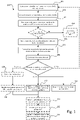
- Fig. 1 is a schematic flow chart representation of a method 100 performed by a computing system for performance evaluation and for weakly annotating data for training/updating of a perception-development module of a vehicle in accordance with an embodiment of the present invention.
- the method 100 may also be understood as a method performed by an in-vehicle computing system for weakly supervised learning of a perception-development module.
- the vehicle is further equipped with an Automated Driving System (ADS).
- ADS Automated Driving System
- the term "perception-development module” may be understood as "Module Under Test” (MUT), meaning that is a "new" (under development) software and/or hardware perception feature.
- MUT Module Under Test
- the perception feature may for example be an object detection feature, an object classification feature, an object state estimation feature, a road reference estimation feature, a free-space estimation feature, a road friction estimation feature, an object trajectory estimation feature, a target/object tracking feature, and/or drivable area estimation feature.
- the perception-development module may in the present context be understood as software and/or hardware configured to generate a perception output, where the module is currently "under development", and not yet “in production” (e.g. not verified/validated).
- the method 100 comprises storing 101, during a time period, sensor data obtained from one or more vehicle-mounted sensors.
- vehicle-mounted sensors may be represented by any arbitrary sensors adapted to sense and/or perceive the vehicle's surroundings and/or whereabouts, and may e.g. refer to one or a combination of one or more of radar, LIDAR, sonar, camera, navigation system e.g. GPS, odometer and/or inertial measurement units.
- the term obtaining is herein to be interpreted broadly and encompasses receiving, retrieving, collecting, acquiring, and so forth.
- the method 100 further comprises storing 102, during the time period, a first set of perception data obtained from a perception module (may also be referred to as a perception system) of the vehicle.
- the perception module is configured to generate the first set of perception data based on sensor data obtained from one or more vehicle-mounted sensors during the time period.
- a perception module is in the present context to be understood as a system responsible for acquiring raw sensor data from on-board sensors such as cameras, LIDARs RADARs, ultrasonic sensors, navigation system e.g. GPS, odometer and/or inertial measurement units, and converting this raw data into scene understanding.
- perception/sensor data may refer to “storing in one or more memories”, “storing on-board said vehicle”, “storing in one or more memories on-board said vehicle”, and/or “storing digitally and/or electronically” a set of perception/sensor data, and further to “collecting” and/or “obtaining” a set of perception data.
- set of perception/sensor data may refer to “range”, “amount”, “series”, “continuous and/or intermittent flow” and/or “collection” of perception/sensor data, whereas “perception data” may refer to “continuously and/or intermittently collected perception data”.
- perception data may referto “surroundings assessment” data, “spatial perception” data, “processed sensory” data and/or “temporal dependencies” data, whereas perception “data” may refer to perception "information” and/or “estimates”.
- obtained” from a perception module may refer to “derived” from a perception model and/or “based on output data” from a perception module.
- perception module configured to "generate the set of perception data” may refer to perception module/system adapted and/or configured to "estimate the surroundings of said vehicle", “estimate at least a portion of surroundings of said vehicle”, “determine surroundings of said vehicle”, “interpret sensory information relevant for the autonomous manoeuvring of said vehicle”, and/or “estimate surroundings of said vehicle and make model predictions of future states of the surroundings of said vehicle”.
- time period may refer to “pre-determinable time period” and/or “predetermined time period”.
- time point may refer to "point in time”
- from a first time point to a second time point may refer to "from a first time point to a subsequent second time point”.
- the method 100 comprises, forming 103, by post-processing the stored 101 first set of perception data, a baseline worldview.
- the baseline worldview comprises information indicative of a scenario in the surrounding environment of the vehicle during the time period.
- a scenario may be a momentary scene at a point in time during the time period including the positions of detected objects, object classes/types, positions of lane markers, extensions of lane markers, free-space detections, and/or trajectories of detected objects. It should be noted that this list merely serves to exemplify the parameters included in a "scenario" and may include other parameters detectable by the vehicle's perception module as readily understood by the skilled person in the art.
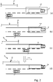
- Fig. 2 depicts a series (a) - (d) of schematic top-view illustrations of a vehicle 1 moving a road portion towards an external object 24. Each illustration is associated with a point in time within the time period 21 ranging from a first moment in time T1 to a second moment in time T2.
- the vehicle 1 (may also be referred to as ego-vehicle 1) is moving towards an external object, here in the form of a truck 24, that is traveling in the same direction on an adjacent lane on the road portion.
- an external object here in the form of a truck 24
- the vehicle's perception system/module may not be able to determine, with a sufficiently high level of accuracy, the position of the external object, and to classify it as a truck.
- the vehicle 1 is closer to the external object, and the uncertainties regarding the external object's 24 position and class/type are reduced, as indicated by the reduced size of the box 22b as compared to the first box 22a.
- the vehicle's 1 perception system/module is able to accurately determine the external object's 2 position and classify it as a truck 2. More specifically, the ego-vehicle 1 is now sufficiently close to the truck 2 to be able to classify it and estimate the truck's position on the road with a higher level of accuracy as compared to when the ego-vehicle 1 was located further away from the truck.
- the filtering may for example be based on the temporal development of the trajectories, positions, etc. in combination with predefined models (e.g. motion models) of the vehicle 1 and external objects 2.
- This established baseline worldview may subsequently used as a "ground truth” for training and/or validation of various perception output, and in particular for training and/or validation of the output obtained from the perception-development module.
- the baseline world-view constitutes a ground truth for the second set of perception data.
- the step of forming 102 the baseline worldview comprises determining, based on post-processing a portion of the first set of perception data ranging back from the second time point to an intermediate time point between the first time point T1 and second time point T2 the baseline worldview indicative of the surrounding environment of the vehicle.
- the baseline worldview accordingly being conditional on the portion of the first set of perception data.
- the post-processing of the portion of the first set of perception data comprises running the portion of the first set of perception data through a backwards filter.
- the backwards filter is configured to align a set of perceptive parameters of the first set of perception data at the intermediate time point based on a development of the state(s) of the set of perceptive parameters from the intermediate time point to the second time point T2.
- the post processing may for example comprise running the first set of perception data through a backwards filter configured to align e.g. the objects current and predicted future states with what happened in the future - i.e. from the intermediate time point to the second time point T2.
- the post-processing may include further processing steps than running it through a backwards filter.
- the post-processing may include fusion of data from various sensors, as well as applying backward and forward filtering on the fused information.
- Suitable filters for this purpose may for example be Particle filters or different types of Kalman filters (e.g. extended Kalman filters).
- the method 100 may further comprise checking a reliability of the formed 103 baseline worldview.
- the reliability check may be performed as a by-product of the post-processing of the outputs of all sensors in the vehicle in an analogous manner as the post-processing 103 of the output from the perception module of the production platform. If the baseline worldview fails the reliability check, the entire associated scenario may be stored as a scenario for development of the perception module of the production platform, by transmitting the stored 101 sensor data and the stored 102 set of perception data to the remote entity, where it can be manually analysed.
- the post-processing 103 may be configured to inherently generate an indication of the reliability of the baseline worldview.
- the post-processing module generates the baseline worldview by processing the data produced by production perception system over a time interval, e.g., [T1, T2] as depicted in Fig. 2 . Going along with the object detection example of Fig.2 .
- the perception algorithms used by the platform perception system
- This information may subsequently be used to estimate the degree to which one can trust on the baseline worldview. For instance, if the object in front of vehicle 1 in Fig.2 is classified as a truck with confidence level of 50% during the time period T1 to T2, a post-processing of its trajectory cannot produce a reliable baseline worldview as the level of confidence on its object class is too low (e.g. below some threshold) during the entire time interval. However, if it were classified as a truck with probability of 90%, the post-processing of this information would generate a more "reliable" baseline worldview.
- Another example of how to measure the degree of reliability (or precision) of the baseline worldview is to measure the deviation of e.g. a post-processed trajectory of a detected object, from its instantaneous detections before post-processing. A larger deviation consequently means that the baseline worldview is less reliable.
- any discrepancy would capture a scenario where it would be difficult for the underlying models (of the production platform) to make a concrete prediction/estimate/reading. Thereby, one would basically be capturing cases of high uncertainty (uncertainty of the external environment). These cases are useful for training of future perception models as it is (likely) a difficult environmental scenario. Thus, one may consider such scenarios to be so-called "corner-cases" for perception development and by storing these one could speed up the development of future high-performance systems.
- This reliability check of the baseline worldview may advantageously be performed prior to any evaluation 105 of the second set of perception data in order to avoid propagating errors from the perception module of the production platform to the perception-development module. Thus, in some embodiments, the evaluation 105 of the second set of perception data with reference to the baseline worldview is only performed if the baseline worldview passes the reliability check.
- the method 100 further comprises storing 104 a second set of perception data from the perception-development module.
- the perception-development module is configured to generate the second set of perception data based on a perception model and sensor data obtained from one or more vehicle-mounted sensors during the time period.
- the second set of perception data is indicative of at least one perceptive parameter of the surrounding environment of the vehicle during at least a moment in time within the time period.
- the second set of perception data may comprise a set of bounding boxes indicating a position and classification of a set of external objects (e.g. one or more vehicles) in the surrounding environment of the vehicle.
- perception model is in the present context to be understood as a software algorithm configured to receive input in the form of sensor data (raw or having some level of preprocessing) and to therefore generate an output comprising a representation of at least a portion of the surrounding environment of the vehicle.
- the perception model may for example be in the form of a neural network, and the model parameters may accordingly be in the form of network weights.
- the sensor data, the first set of perception data, and the second set of perception data may for example be stored or saved in one or more data buffers.
- the first and second sets of perception data may, as mentioned, for example be detected objects or objects' states and/or vehicle localization, and/or statistical and physical model predictions of future states, derived continuously and/or intermittently from a first time point T1 to a second time point T2.
- the time period - and correspondingly the length of the optional data buffers - may be of any arbitrary size deemed feasible, e.g. in consideration of data capacity restraints and/or characteristics of the ADS, and may for instance range from under a second up to several minutes, or more preferred, from a few seconds up to less than a minute.
- the method 100 comprises evaluating 105 the second set of perception data against the formed 103 baseline worldview in order to identify a match between the perceptive parameter of the second set of perception data and a corresponding perceptive parameter in the baseline worldview.
- the evaluation 105 may be construed as a comparison step between the second set of perception data and the formed baseline worldview so to identify a level of matching between one or more perceptive parameters (e.g. object positions) in the second set of perception data and the corresponding perceptive parameters in the baseline worldview.
- the term "evaluating" the second set of perception data against the formed baseline worldview as used herein may be understood as “processing" the second set of perception data and the formed baseline worldview in order to identify a match between the perceptive parameter of the second set of perception data and a corresponding perceptive parameter in the baseline worldview.
- a purpose of the evaluation 105 is to match an object detected based on second set of perception data with one object from the base line world view both corresponding to one unique object in the real world. After the corresponding objects from the two sets of perception data are matched together, the next step is to compare their perceptive parameter(s) (e.g. position, speed, heading, etc.) and evaluate the performance of MUT.
- perceptive parameter(s) e.g. position, speed, heading, etc.
- the evaluation 105 may include comparing the position of an identified vehicle in the second set of perception data with the position of the corresponding vehicle in the baseline worldview (e.g. as illustrated in Fig. 4 ).
- the matching 104 process will be further exemplified and elucidated with reference to Figs. 4 - 6 .
- the method 100 further comprises determining 106 an estimation error (e) of the matched perceptive parameter of the second set of perception data in reference to the corresponding perceptive parameter in the baseline worldview.
- the estimation error (e) may be construed as a parameter indicative of how well the "matching" perceptive parameters correlate.
- the estimation error (e) may in some embodiments be construed as the "level of matching" between two perceptive parameters.
- the method 100 further comprises at least one of the following steps.
- the threshold for the estimation error may be defined in different ways depending on the type of perceptive parameter that is being evaluated.
- the perceptive parameter may be an object position estimation or an object occupancy estimation.
- the threshold may then be in the form of a "maximum lateral and longitudinal offset of closest point" between the bounding box representation of an object in the second set of perception data and the bounding box representation of the corresponding object in the baseline worldview.
- the term "closest point” may be understood the closest point of the detected object to the ego-vehicle.
- the threshold may also be in the form of a "maximum lateral and longitudinal offset" of any point of the two bounding box representations (e.g. bottom left corner, top right corner, etc.).
- the threshold may be in the form of a "maximum size" (i.e. number of area units) of a non-overlapping free-space area between the free-space area estimations of the second set of perception data and the baseline worldview. In terms of set theory this may be understood as the symmetric difference between the free-space set defined by the free-space estimation of the perception development module and the free-space set defined by the baseline worldview. Moreover, in some embodiments, there is a plurality of different thresholds associated with the free-space estimation, where the thresholds depend on where the "erroneous" portion is located relative to the ego-vehicle.
- estimation error thresholds for various perceptive parameters as exemplified herein.
- This value may be set based on the type of parameter and/or based on the level of maturity of the perception-development module.
- the estimation error may in some embodiments be set to zero or any value above zero, meaning if there is any discrepancy between the perception-development module's output and the baseline worldview, the weak annotation step is triggered.
- the method 100 goes to a next iteration of processing the buffered data.
- the method 100 may comprise determining 109 a cost function based on the determined 106 estimation error (e), where the cost function is indicative of a performance of the perception-development module.
- the cost function is indicative of a performance of the perception-development module.
- the cost function may also be referred to as a loss function
- the cost function is determined based on the type of perceptive parameter. In other words, one cost function may be formed/defined if the perception model of the perception-development module is an object detection algorithm while another cost function may be formed/defined if it is a lane-tracing/tracking algorithm.
- one or more parameters of the perception-development module may be updated 110 by means of an optimization algorithm (e.g. back propagation for neural networks) configured to minimize the calculated cost function.
- an optimization algorithm e.g. back propagation for neural networks
- the determination 109 of the cost-function is only performed if the estimation error (e) between the perceptive parameter of the second set of perception data and a corresponding perceptive parameter in the baseline worldview is below or within a threshold range (e.g. [0, x1]).
- a threshold range e.g. [0, x1]
- the evaluation 105 of the second set of perception data to the formed baseline worldview is only performed on the second set of perception data and the baseline worldview representative of a region of interest in the surrounding environment of the vehicle. For example, one may limit an "area" within which the evaluation process 105 is performed, such that one only compares the two datasets represented an area within a specific viewing frustum or within a certain distance from the vehicle. Thereby, objects that are further away from the vehicle may be ignored as they are more likely to be associated with higher uncertainties and therefore more difficult to "match”. Similarly, one may ignore "less relevant" areas during the evaluation 105, such as e.g. opposing lanes on a controlled access highway.
- the region of interest may be set dynamically depending on one or more vehicle parameters, such as e.g. the speed of the ego-vehicle. For example, if the vehicle is moving at low speeds (e.g. ⁇ 20 km/h), the region of interest may be set to include a smaller area around the ego-vehicle as compared to a corresponding situation when the vehicle is traveling at high speeds (e.g. > 100 km/h). This may consequently result in reduced processing power requirements for the evaluation process 105.
- vehicle parameters such as e.g. the speed of the ego-vehicle. For example, if the vehicle is moving at low speeds (e.g. ⁇ 20 km/h), the region of interest may be set to include a smaller area around the ego-vehicle as compared to a corresponding situation when the vehicle is traveling at high speeds (e.g. > 100 km/h). This may consequently result in reduced processing power requirements for the evaluation process 105.
- the method 100 further comprises transmitting 111 the one or more updated parameters of the perception model of the perception-development module to a remote entity.
- the remote entity may for example be a central system or a cloud system capable of receiving and transmitting data to a fleet of ADS-equipped vehicles.
- the method 100 comprises receiving 112 a set of globally updated parameters of the perception model of the perception-development module from the remote entity. The set of globally updated parameters are accordingly based on information obtained from a plurality of vehicles comprising the perception-development module. Once, the set of globally updated parameters have been received 112, the method 100 may further comprise updating 113 the perception model of the perception-development module based on the received set of globally updated parameters.
- the remote entity (may also be referred to as the "back-office"), consolidates the "learned" parameters of each vehicle in the entire fleet of vehicles, and pushes an update of the perception-development module to each vehicle in the fleet.
- the remote entity may utilize an entire fleet of production vehicles (instead of a few specialized "test-vehicles") to develop and verify various perception features associated with an ADS.
- model parameters e.g. network weights
- the "back-office” may in the present context be understood as a central entity responsible for the management and maintenance of the ADSs deployed in the vehicle fleet.
- Executable instructions for performing these functions are, optionally, included in a non-transitory computer-readable storage medium or other computer program product configured for execution by one or more processors.
- the present invention provides a time-efficient and cost-effective solution for developing consecutive releases of perception features for autonomous vehicles.
- the present inventors realized that once there is a "first" ADS released and deployed in a fleet of production vehicles, one can capitalize on the huge efforts (in terms of time and financial investments) associated with this first release, in order to develop consecutive releases of various perception features.
- the vehicles "out in traffic" i.e. production vehicles
- the solution proposed herein may be understood as a scheme of federated learning, effectively using learning at the edge (in each production vehicle) and then to potentially consolidate the learnt parameters/weights in a central/cloud unit.
- the present invention provides a solution that utilises the production vehicles to develop new perception features related to new sensor hardware as well as new algorithms for existing sensors by using federated learning.
- perception algorithms for autonomous driving such as for example "vision” algorithms
- hand-labelled (annotated) data for training of the machine learning models.
- Creating such hand-labelled datasets is not only very expensive but also extremely time consuming, especially when domain expertise is required.
- the present invention aims to mitigate these problems by automatically selecting the most informative part of the data for annotation as well as enabling automatic weak annotations and thereby alleviate the requirements of massive hand-labelled datasets.
- the perception platform deployed in the fleet of production vehicles to identify and weakly annotate sets of data that can substantially improve the performance of the new generations of perception features related to new sensor hardware as well as new algorithms for existing sensors.
- the vehicle's own worldview is supplied as a baseline towards which the output of the software- (SW) or hardware- (HW) -under-development is compared.
- SW software-
- HW hardware-
- the data is weakly (i.e., "inaccurately") annotated by the baseline worldview.
- Such weakly annotated data may subsequently be used to update the SW parameters of the "perception model" in the module-under-test in each individual vehicle, or to be transmitted to the "back-office” for off-board processing or more accurate annotations.
- the herein proposed methods and system effectively enable cost-efficient data annotation for the "next generation” perception modules, thereby reducing costs and time-efforts needed for developing future products/systems.
- the present inventors realized that once the ADS in the production vehicles is deployed, it can be assumed that it has been proven sufficiently safe (at least under certain conditions) including the perception and its performance. Therefore, a learning regime is herein proposed, where the worldview of the ADS is post-processed to construct a "baseline", towards which the output of the software-/hardware-under-development can be compared. Through this comparison one can setup a system to automatically annotate the worldview for the module-under-development and use this weakly annotated data for weakly supervised learning locally in each production vehicle, or to send the annotated data to the "back-office" for offline processing or possibly for more accurate annotation.
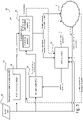
- Fig. 3 is a schematic block diagram representation of a system 10 for weakly annotating data for training of a perception-development module of a vehicle, where the vehicle is equipped with an Automated Driving System (ADS).
- ADS Automated Driving System
- Fig. 3 depicts the flow of information through exposure to an event in the vehicle to the transmission and subsequent consolidation in the "back-office" 2.
- the system 10 comprises control circuitry configured to perform the functions of the methods disclosed herein, where the functions may be included in a non-transitory computer-readable storage medium or other computer program product configured for execution by the control circuitry.
- the control circuitry is represented as various "modules" in Fig. 3 , each of them linked to one or more specific functions.
- perception output for evaluation that is compared in the “evaluation engine” 35 could be any type of perception output e.g. objects, their states, free-space (the absence of objects), lanes, road position, driveable area, and combinations thereof.
- Free-space areas may in the present context be understood as areas in the surrounding environment of the ego-vehicle absent of objects (e.g. other vehicles, pedestrians, barriers, animals, bicycles, static objects, etc.).
- the system 10 comprises control circuitry configured to store, during a time period, sensor data 31 obtained from a set of vehicle-mounted sensors configured to monitor a surrounding environment of the vehicle.
- the sensor data 31 may for example output from one or more of a RADAR device, a LIDAR device, a camera, and ultrasonic sensor, and so forth.
- the control circuitry is further configured to store a first set of perception data obtained from the perception module 32 of the vehicle.
- the perception module 32 is configured to generate the first set of perception data based on the sensor data 31 obtained from one or more vehicle-mounted sensors during the time period.
- a "perception module" i.e.
- the perception system of the production platform is in the present context to be understood as a system responsible for acquiring raw sensor data from onboard sensors such as cameras, LIDARs and RADARs, ultrasonic sensors, and converting this raw data into scene understanding including state estimations and predictions thereof (i.e. to a "worldview").
- the data sets may for example be stored or saved in a data buffer (not shown), where the first and second sets of perception data may be understood as data indicative of the vehicle's surroundings.
- This may for example be detected objects or objects' states and/or vehicle localization, and/or statistical and physical model predictions of future states, derived continuously and/or intermittently from a first time point T1 to a second time point T2.
- the time period - and correspondingly the length of the optional data buffer - may be of any arbitrary size deemed feasible, e.g. in consideration of data capacity restraints and/or characteristics of the ADS, and may for instance range from under a second up to several minutes, or more preferred, from a few seconds up to less than a minute.
- the system 10 comprises a post-processing module 33 for forming a baseline worldview indicative of a scenario in the surrounding environment of the vehicle during the time period.
- the baseline worldview is formed based on the perception data generated by the perception module 32 of the production ADS. It should be noted that the term "forming, by post-processing the first set of perception data" does not necessarily mean that all of the stored data is post-processed, but should be construed as that at least a portion or at least a range of the stored perception data is post-processed.
- a second set of perception data is generated by a perception-development module (i.e. a Module Under Test, MUT) 34.
- This second set of data is obtained or received by an "evaluation engine” 35 of the system 10.
- the perception-development module 34 is configured to generate the second set of perception data based on a perception model and sensor data obtained from one or more vehicle-mounted sensors during the time period.
- the second set of perception data may be understood as a "perception output" from the MUT 34, and it is indicative of a perceptive parameter of the surrounding environment of the vehicle.
- the MUT 34 may comprise a lane tracing/tracking algorithm or a road geometry estimation algorithm.
- the output from the MUT may be a road reference feature estimation, such as e.g. a representation of the road or lane geometry in the surrounding environment of the vehicle during the time period.
- the input to the perception-development module 34 could be any combination of existing production sensors, their raw output, the raw detections or any more or less processed state in the chain. It could also be any combination of newly mounted sensors and their output (i.e. sensor output that is not used to generate the baseline worldview). For example, if one would want to test and evaluate an object detection algorithm that is based on a different type of input data from a new type of sensor as compared to the "production platform's" object detection algorithm.
- the evaluation engine 35 is configured to evaluate the second set of perception data in reference to the formed baseline worldview in order to identify a match between one or more perceptive parameters of the second set of perception data and the corresponding perceptive parameters in the baseline worldview. In other words, the evaluation engine 35 is configured to try to match the "perception-output for evaluation" with the corresponding features in the baseline worldview. If a match is found, the evaluation engine 35 is further configured to derive an estimation error.
- the outputs that are compared in the "evaluation engine” 35 could be any type of perception output e.g. objects, their states or free-space (the absence of objects), lanes, road position, and driveable area, or combinations thereof.
- an estimation error of the matched perceptive parameter of the second set of perception data in reference to the corresponding perceptive parameter in the baseline worldview is determined.
- the evaluation engine may transmit a signal to a learning engine 36.
- This transmitted signal may comprise an instruction to update one or more parameters of the perception model of the perception-development module 34 by means of a weakly supervised learning algorithm based on the sensor data used for the second set of perception data and by using the baseline worldview to weakly annotate the second set of perception data.
- the system may be configured to transmit the weakly annotated data to the back-office 2 for offline processing (e.g. manual annotation or analysis).
- the data transmitted to the back-office may advantageously be used to improve the production platform's perception module 32 as well.
- the evaluation engine 35 is configured to evaluate the obtained second set of perception data in reference to the baseline worldview in order to determine a cost function.
- the cost function is calculated based on the determined estimation error, and is indicative of a performance of the perception-development module.
- the determined cost function may then be transmitted to the learning engine 36, which is configured to update one or more parameters of the perception model of the perception-development module 34 by means of an optimization algorithm (e.g. back propagation for neural networks) configured to minimize the calculated cost function.
- an optimization algorithm e.g. back propagation for neural networks
- the learning engine 36 is further configured to transmit the one or more locally updated parameters to a remote entity 2, where they are consolidated with updates received from other vehicles in the fleet, and then transmitted back to the learning engine 36 as a set of globally updated parameters. Then, the learning engine 36 may update the perception model of the perception-development module 34 based on the received set of globally updated parameters.
- the learning platform as proposed herein exposes the vision/perception baseline locally inside the platform such that the comparison/cost function used for evaluation or learning of the perception-development module 34 can be customised according to the present need. Further, the platform is proposed to include the redundant computational power necessary to achieve the comparison as well as the learning steps.
- the system 10 provides a means for weakly annotating data for training of a perception-development module of a vehicle by comparing the output from the "Module-under-test" 34 with the baseline worldview (serving as a ground truth).
- the comparison may, in some embodiments, be evaluated through a customisable cost function. If the value of the cost function is found to be over a set threshold or if a mismatch is found between the two outputs (e.g. if it is impossible to match parts of the world views to get a reliable value for calculating a cost function), the baseline worldview can be used as a weak annotation of the worldview for the module-under-test 34. It is called weak annotation of the worldview due to possible uncertainties and inaccuracies in baseline worldview in comparison to a hand-labelled worldview.
- the weekly annotated data may subsequently used in two different ways:
- the choice between these two options may for example depends on the level of confidence of the baseline worldview, which can be obtained as a by-product of a post-processing of the outputs of all sensors in the production vehicle. If the discrepancy between the "baseline worldview" and post-processed sensor worldviews are in regions where the baseline worldview has inherently low confidence, or if the "perception development module" 34 is very immature it may benefit a lot from manually annotated data in back-office. However, in comparison to conventional data annotation processes where massive datasets are used and a great deal of time and effort is spent on review and analysis in order to find the "suitable" datasets for supervised learning. The herein proposed solution can also be utilized to automatically provide high-quality data sets for offline processing (e.g. hand-labelling), which drastically decreases the required time and effort for development of new perception models for autonomous driving applications.
- offline processing e.g. hand-labelling
- the methods and systems as disclosed herein could be used to develop and launch new perception software or hardware versions in accordance with the following stages.
- a learning stage or phase and a consolidation phase where the new module is updated according to the flows depicted in Figs. 1 and 3 .
- the consolidated model parameters are pushed to the vehicle fleet for validation.
- the "learning part" of the process is not executed, i.e. in reference to Fig. 3 , the learning engine 36 is "short-circuited". Thus, only the evaluation part of the process is used.
- the new module passes the validation phase (i.e. the fail-rate is sufficiently low) in each vehicle of the fleet of vehicles, the final SW can be launched. However, if the validation fails, one can return to the beginning and start a new iteration of the process.
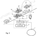
- Fig. 4 is a schematic perspective view of a matching process for matching a second set of perception data to a formed baseline worldview.
- the second set of perception data comprises an object detection estimation, and an example of how a matching between the two datasets outside of a threshold may be propagated to the evaluation and learning engines 34, 36 either to update the model parameters of the perception-development module of the vehicle 1 or to transmit weakly annotated data to the "back-office" 2.
- the determined estimation error (as indicated by the double-headed arrows) may for example a difference in the location between the bounding boxes around the detected objects 41 indicated in the second set of perception data and the bounding boxes around the corresponding objects 42 in the baseline worldview.
- Fig. 4 also serves to elucidate the matching process described in the foregoing.
- a match between the perceptive parameters (objects) of the second set of perception data and the corresponding perceptive parameters (objects) in the baseline worldview was identified for two of the vehicles 41a-b detected by the perception-development module, while no match could be identified for a third vehicle 41c.
- an estimation error is determined and compared against a threshold. In the case where no match could be identified/established (i.e. the objects within the broken-line circle in Fig. 4 ), one can define the estimation error for this perceptive parameter 41c as "infinite" or some "maximum value".
- the matching process ensures that the red vehicle is matched to the corresponding red vehicle in the baseline worldview and the blue vehicle is matched to the corresponding blue vehicle in the baseline worldview. Otherwise, the perception model of the perception-development module may be trained with erroneous data (based on erroneous conclusions), which would decrease the performance of the perception-development module. Thus, as illustrated in Fig. 4 , the third vehicle 41c as detected by the perception-development module was not sufficiently close to any vehicle in the baseline worldview for the evaluation engine to identify any match.
- the perception model of the perception development module generates an inaccurate representation of the surrounding environment.
- a weakly supervised learning algorithm where the sensor data used for generating the second set of perception data and the baseline worldview together form a "training dataset" or a "training example”. More specifically, the sensor data used for the second set of perception data forms the "input object" and the baseline worldview is used as weakly annotated data in order to form a "supervision signal" (i.e. "desired output”).
- Figs. 5 and 6 show the corresponding evaluation processes for perception models in the form of lane geometry estimations algorithms ( Fig. 5 ) and free-space detection algorithms ( Fig. 6 ).
- Fig. 5 is a schematic top-view illustration of a vehicle according to an embodiment of the present invention traveling on a road portion.
- the road portion has two lanes, and curves to the left in front of the vehicle 1.
- the "true" lane markings are indicated by reference numeral 53
- the baseline worldview's lane geometry estimation is indicated by reference numeral 52
- the perception-development module's lane geometry estimation is indicated by reference numeral 51.
- the baseline worldview is utilized as weakly annotated data for updating one or more parameters of the perception model of the perception-development module by means of a weakly supervised learning algorithm or for transmitting to the back-office.
- the estimation error 55 is indicated as a difference between the locations/geometries of the lane geometry estimations 51, 52.
- the perception-development module's lane geometry estimation 51 failed to generate a representation of the lane markers in some areas (indicated by reference numeral 55).
- the evaluation is performed in the image plane on a pixel level. Thereby, one can evaluate and train camera software directly on the pixel level.
- Fig. 6 is a schematic top-view illustration of a vehicle according to an embodiment of the present invention traveling on a road portion.
- the road portion has two lanes, and three external objects 63 in the form of two cars and a tractor located in front of the vehicle.
- the free-space estimation made by the production platform i.e. the free-space estimation of the baseline worldview is indicated by reference numeral 62, while the free-space estimation of the perception-development module is indicated by reference numeral 61.
- the estimation error 65', 65" is, in the illustrated example, simply derived by a measurement or metric indicative of the non-overlapping parts of the two free-space estimations 61, 62. In terms of set theory this may be understood as the symmetric difference between the free-space set defined by the free-space estimation 61 of the perception development module and the free-space estimation 62 defined by the baseline worldview.
- the mismatching or estimation error 65' 65" is above a threshold, the stored data is used for training the perception model of the perception development module or transmitted to the back-office 2 for further analysis.
- the perception-development module's free-space estimation 62 is associated with two different estimation errors 65', 65", where the smaller deviation from the "ground truth” 61 is indicated by reference numeral 65' and the larger deviation is indicated by reference numeral 65".
- the larger deviation or estimation error 65" is considered to be above some "maximum error threshold” and the data is sent to the back-office 2 for hand-annotation/further analysis.
- the smaller deviation or estimation error 65' is on the other hand considered to be below this "maximum threshold" and can therefore be used to locally update the perception model in accordance with the foregoing embodiments.
- free-space areas may in the present context be understood as areas in the surrounding environment of the ego-vehicle absent of objects (e.g. other vehicles, pedestrians, barriers, animals, bicycles, static objects, etc.).
- the location of free-space areas may be understood as estimates of areas absent of external objects (static and dynamic objects).
- Fig. 7 depicts a schematic side view of a vehicle 1 comprising a system 10 for weakly annotating data for training of a perception-development module of an ADS-equipped vehicle in accordance with an embodiment of the present invention.
- the vehicle 1 further comprises a perception module/system 6 (i.e. the perception system of the production platform), and a localization system 5.
- a perception system 6 is in the present context to be understood as a system responsible for acquiring raw sensor data from on-board sensors 6a, 6b, 6c such as cameras, LIDARs and RADARs, ultrasonic sensors, and converting this raw data into scene understanding.
- the localization system 5 is configured to monitor a geographical position and heading of the vehicle, and may in the form of a Global Navigation Satellite System (GNSS), such as a GPS.
- GNSS Global Navigation Satellite System
- RTK Real Time Kinematics
- the perception module/system 6 may refer to any commonly known system and/or functionality, e.g. comprised in one or more electronic control modules and/or nodes of the vehicle 1, adapted and/or configured to interpret sensory information - relevant for driving of the vehicle 1 - to identify e.g. obstacles, vehicle lanes, relevant signage, appropriate navigation paths etc.
- the exemplified perception system 6 may thus be adapted to rely on and obtain inputs from multiple data sources, such as automotive imaging, image processing, computer vision, and/or in-car networking, etc., in combination with sensory information.
- Such exemplifying sensory information may for instance be derived from one or more optional surrounding detecting sensors 6 comprised in and/or provided on-board the vehicle 1.
- the surrounding detecting sensors 6 may be represented by any arbitrary sensors adapted to sense and/or perceive the vehicle's 1 surroundings and/or whereabouts, and may e.g. refer to one or a combination of one or more of radar, LIDAR, sonar, camera, navigation system e.g. GPS, odometer and/or inertial measurement units.
- the system 10 comprises one or more processors 11, a memory 12, a sensor interface 13 and a communication interface 14.
- the processor(s) 11 may also be referred to as a control circuit 11 or control circuitry 11.
- the control circuitry 11 is configured to execute instructions stored in the memory 12 to perform a method for weakly annotating data for training of a perception-development module of a vehicle 1 according to any one of the embodiments disclosed herein.
- the memory 12 of the control device 10 can include one or more (non-transitory) computer-readable storage mediums, for storing computer-executable instructions, which, when executed by one or more computer processors 11, for example, can cause the computer processors 11 to perform the techniques described herein.
- the memory 12 optionally includes high-speed random access memory, such as DRAM, SRAM, DDR RAM, or other random access solid-state memory devices; and optionally includes non-volatile memory, such as one or more magnetic disk storage devices, optical disk storage devices, flash memory devices, or other non-volatile solid-state storage devices.
- high-speed random access memory such as DRAM, SRAM, DDR RAM, or other random access solid-state memory devices
- non-volatile memory such as one or more magnetic disk storage devices, optical disk storage devices, flash memory devices, or other non-volatile solid-state storage devices.
- the control circuitry 11 is configured to store, during a time period, sensor data obtained from one or more vehicle-mounted sensors configured to monitor a surrounding environment of the vehicle.
- the control circuitry 11 is further configured to store, during the time period, a first set of perception data obtained from the perception module 6 (of the "production platform") of the vehicle.
- the perception module 6 is configured to generate the first set of perception data based on sensor data obtained from one or more vehicle-mounted sensors 6 during the time period.
- the control circuitry 11 is configured to form, by post-processing the first set of perception data, a baseline worldview indicative of a scenario in the surrounding environment of the vehicle during the time period.
- the control circuitry 11 is further configured to obtain a second set of perception data from the perception-development module (not shown in Fig. 7 ), where the perception-development module is configured to generate the second set of perception data based on a perception model and sensor data obtained from one or more vehicle-mounted sensors 6 during the time period.
- the second set of perception data is indicative of a perceptive parameter of the surrounding environment of the vehicle during the time period.
- the sensor data used for generating the first set of perception data need not be the same sensor data as used for generating the second set of perception data.
- the first set of perception data is generated based on a first set of sensor data
- the second set of perception data is generated based on a second set of sensor data.
- first set of sensor data is the same as the second set of sensor data, while in other embodiments the second set of sensor data is a subset of the first set of sensor data. Alternatively, the first set of sensor data is different from the second set of sensor data.
- control circuitry 11 is configured to evaluate the obtained second set of perception data against the formed baseline worldview in order to identify a match between the perceptive parameter of the second set of perception data and a corresponding perceptive parameter in the baseline worldview. Then, if a match between the perceptive parameter of the second set of perception data and the corresponding perceptive parameter in the baseline worldview is identified, the control circuitry is further configured to determine an estimation error of the matched perceptive parameter of the second set of perception data in reference to the corresponding perceptive parameter in the baseline worldview.
- control circuitry is further configured to perform at least one of the following:
- the vehicle 1 may be connected to external network(s) 20 via for instance a wireless link (e.g. for transmitting and receiving model parameters).
- a wireless link e.g. for transmitting and receiving model parameters
- the same or some other wireless link may be used to communicate with other vehicles in the vicinity of the vehicle or with local infrastructure elements.
- Cellular communication technologies may be used for long range communication such as to external networks and if the cellular communication technology used have low latency it may also be used for communication between vehicles, vehicle to vehicle (V2V), and/or vehicle to infrastructure, V2X.
- Examples of cellular radio technologies are GSM, GPRS, EDGE, LTE, 5G, 5G NR, and so on, also including future cellular solutions.
- LAN Wireless Local Area
- ETSI is working on cellular standards for vehicle communication and for instance 5G is considered as a suitable solution due to the low latency and efficient handling of high bandwidths and communication channels.
- a non-transitory computer-readable storage medium storing one or more programs configured to be executed by one or more processors of a vehicle control system, the one or more programs comprising instructions for performing the method according to any one of the above-discussed embodiments.
- a computer-accessible medium may include any tangible or non-transitory storage media or memory media such as electronic, magnetic, or optical media-e.g., disk or CD/DVD-ROM coupled to computer system via bus.
- tangible and non-transitory are intended to describe a computer-readable storage medium (or “memory”) excluding propagating electromagnetic signals, but are not intended to otherwise limit the type of physical computer-readable storage device that is encompassed by the phrase computer-readable medium or memory.
- the terms “non-transitory computer-readable medium” or “tangible memory” are intended to encompass types of storage devices that do not necessarily store information permanently, including for example, random access memory (RAM).
- Program instructions and data stored on a tangible computer-accessible storage medium in non-transitory form may further be transmitted by transmission media or signals such as electrical, electromagnetic, or digital signals, which may be conveyed via a communication medium such as a network and/or a wireless link.
- transmission media or signals such as electrical, electromagnetic, or digital signals, which may be conveyed via a communication medium such as a network and/or a wireless link.
- the processor(s) 11 may be or include any number of hardware components for conducting data or signal processing or for executing computer code stored in memory 12.
- the device 10 has an associated memory 12, and the memory 12 may be one or more devices for storing data and/or computer code for completing or facilitating the various methods described in the present description.
- the memory may include volatile memory or non-volatile memory.
- the memory 12 may include database components, object code components, script components, or any other type of information structure for supporting the various activities of the present description. According to an exemplary embodiment, any distributed or local memory device may be utilized with the systems and methods of this description.
- the memory 12 is communicably connected to the processor 11 (e.g., via a circuit or any other wired, wireless, or network connection) and includes computer code for executing one or more processes described herein.
- the sensor interface 13 may also provide the possibility to acquire sensor data directly or via dedicated sensor control circuitry 6 in the vehicle.
- the communication/antenna interface 14 may further provide the possibility to send output to a remote location (e.g. remote operator or control centre) by means of the antenna 8.
- some sensors in the vehicle may communicate with the system 10 using a local network setup, such as CAN bus, I2C, Ethernet, optical fibres, and so on.
- the communication interface 14 may be arranged to communicate with other control functions of the vehicle and may thus be seen as control interface also; however, a separate control interface (not shown) may be provided.
- Local communication within the vehicle may also be of a wireless type with protocols such as WiFi, LoRa, Zigbee, Bluetooth, or similar mid/short range technologies.
Landscapes
- Engineering & Computer Science (AREA)
- Physics & Mathematics (AREA)
- Theoretical Computer Science (AREA)
- General Physics & Mathematics (AREA)
- Radar, Positioning & Navigation (AREA)
- Remote Sensing (AREA)
- Software Systems (AREA)
- General Engineering & Computer Science (AREA)
- Evolutionary Computation (AREA)
- Artificial Intelligence (AREA)
- Multimedia (AREA)
- Data Mining & Analysis (AREA)
- Computer Networks & Wireless Communication (AREA)
- General Health & Medical Sciences (AREA)
- Health & Medical Sciences (AREA)
- Computing Systems (AREA)
- Electromagnetism (AREA)
- Life Sciences & Earth Sciences (AREA)
- Computer Vision & Pattern Recognition (AREA)
- Databases & Information Systems (AREA)
- Biomedical Technology (AREA)
- Biophysics (AREA)
- Mathematical Physics (AREA)
- Molecular Biology (AREA)
- Computational Linguistics (AREA)
- Medical Informatics (AREA)
- Evolutionary Biology (AREA)
- Bioinformatics & Cheminformatics (AREA)
- Bioinformatics & Computational Biology (AREA)
- Business, Economics & Management (AREA)
- General Business, Economics & Management (AREA)
- Human Resources & Organizations (AREA)
- Marketing (AREA)
- Economics (AREA)
- Tourism & Hospitality (AREA)
- Primary Health Care (AREA)
- Library & Information Science (AREA)
- Quality & Reliability (AREA)
- Strategic Management (AREA)
- Traffic Control Systems (AREA)
Priority Applications (3)
| Application Number | Priority Date | Filing Date | Title |
|---|---|---|---|
| EP21158016.2A EP4047514B1 (fr) | 2021-02-19 | 2021-02-19 | Plateforme de développement de système de perception pour système de conduite automatisée |
| US17/672,798 US11983918B2 (en) | 2021-02-19 | 2022-02-16 | Platform for perception system development for automated driving system |
| CN202210152269.6A CN114968189A (zh) | 2021-02-19 | 2022-02-18 | 用于自动驾驶系统的感知系统开发的平台 |
Applications Claiming Priority (1)
| Application Number | Priority Date | Filing Date | Title |
|---|---|---|---|
| EP21158016.2A EP4047514B1 (fr) | 2021-02-19 | 2021-02-19 | Plateforme de développement de système de perception pour système de conduite automatisée |
Publications (2)
| Publication Number | Publication Date |
|---|---|
| EP4047514A1 true EP4047514A1 (fr) | 2022-08-24 |
| EP4047514B1 EP4047514B1 (fr) | 2023-10-11 |
Family
ID=74732581
Family Applications (1)
| Application Number | Title | Priority Date | Filing Date |
|---|---|---|---|
| EP21158016.2A Active EP4047514B1 (fr) | 2021-02-19 | 2021-02-19 | Plateforme de développement de système de perception pour système de conduite automatisée |
Country Status (3)
| Country | Link |
|---|---|
| US (1) | US11983918B2 (fr) |
| EP (1) | EP4047514B1 (fr) |
| CN (1) | CN114968189A (fr) |
Families Citing this family (2)
| Publication number | Priority date | Publication date | Assignee | Title |
|---|---|---|---|---|
| DE102021207246A1 (de) * | 2021-07-05 | 2023-01-05 | Robert Bosch Gesellschaft mit beschränkter Haftung | Vorrichtung, Speichermedium, Computerprogramm und insbesondere computerimplementiertes Verfahren zur Validierung eines daten-basierten Modells |
| US11814070B1 (en) * | 2021-09-30 | 2023-11-14 | Zoox, Inc. | Simulated driving error models |
Citations (4)
| Publication number | Priority date | Publication date | Assignee | Title |
|---|---|---|---|---|
| WO2019232335A1 (fr) * | 2018-06-01 | 2019-12-05 | Volkswagen Group Of America, Inc. | Méthodologies, systèmes et composants d'apprentissage incrémental et continu pour l'amélioration évolutive de systèmes autonomes |
| WO2020056331A1 (fr) * | 2018-09-14 | 2020-03-19 | Tesla, Inc. | Système et procédé d'obtention de données d'entraînement |
| WO2020079698A1 (fr) * | 2018-10-19 | 2020-04-23 | A.D Knight Ltd. | Test de fonctionnalité de systèmes adas |
| US20200210778A1 (en) * | 2018-12-26 | 2020-07-02 | Yandex.Taxi LLC | Methods and systems for generating training data for neural network |
Family Cites Families (9)
| Publication number | Priority date | Publication date | Assignee | Title |
|---|---|---|---|---|
| US20170160744A1 (en) * | 2015-12-08 | 2017-06-08 | Delphi Technologies, Inc. | Lane Extension Of Lane-Keeping System By Ranging-Sensor For Automated Vehicle |
| US10762358B2 (en) * | 2016-07-20 | 2020-09-01 | Ford Global Technologies, Llc | Rear camera lane detection |
| US10884409B2 (en) * | 2017-05-01 | 2021-01-05 | Mentor Graphics (Deutschland) Gmbh | Training of machine learning sensor data classification system |
| US11042155B2 (en) * | 2017-06-06 | 2021-06-22 | Plusai Limited | Method and system for closed loop perception in autonomous driving vehicles |
| WO2019094843A1 (fr) * | 2017-11-10 | 2019-05-16 | Nvidia Corporation | Systèmes et procédés pour véhicules autonomes sûrs et fiables |
| US11042157B2 (en) * | 2018-07-23 | 2021-06-22 | Baidu Usa Llc | Lane/object detection and tracking perception system for autonomous vehicles |
| US11475248B2 (en) * | 2018-10-30 | 2022-10-18 | Toyota Research Institute, Inc. | Auto-labeling of driving logs using analysis-by-synthesis and unsupervised domain adaptation |
| CN110516633B (zh) * | 2019-08-30 | 2023-05-16 | 的卢技术有限公司 | 一种基于深度学习的车道线检测方法及系统 |
| CN111292366B (zh) * | 2020-02-17 | 2023-03-10 | 华侨大学 | 一种基于深度学习和边缘计算的视觉行车测距算法 |
-
2021
- 2021-02-19 EP EP21158016.2A patent/EP4047514B1/fr active Active
-
2022
- 2022-02-16 US US17/672,798 patent/US11983918B2/en active Active
- 2022-02-18 CN CN202210152269.6A patent/CN114968189A/zh active Pending
Patent Citations (4)
| Publication number | Priority date | Publication date | Assignee | Title |
|---|---|---|---|---|
| WO2019232335A1 (fr) * | 2018-06-01 | 2019-12-05 | Volkswagen Group Of America, Inc. | Méthodologies, systèmes et composants d'apprentissage incrémental et continu pour l'amélioration évolutive de systèmes autonomes |
| WO2020056331A1 (fr) * | 2018-09-14 | 2020-03-19 | Tesla, Inc. | Système et procédé d'obtention de données d'entraînement |
| WO2020079698A1 (fr) * | 2018-10-19 | 2020-04-23 | A.D Knight Ltd. | Test de fonctionnalité de systèmes adas |
| US20200210778A1 (en) * | 2018-12-26 | 2020-07-02 | Yandex.Taxi LLC | Methods and systems for generating training data for neural network |
Also Published As
| Publication number | Publication date |
|---|---|
| CN114968189A (zh) | 2022-08-30 |
| EP4047514B1 (fr) | 2023-10-11 |
| US20220270356A1 (en) | 2022-08-25 |
| US11983918B2 (en) | 2024-05-14 |
Similar Documents
| Publication | Publication Date | Title |
|---|---|---|
| US12377837B2 (en) | Path planning in autonomous driving environments | |
| US12195021B2 (en) | Platform for perception system development for automated driving system | |
| US12222726B2 (en) | Platform for path planning system development for automated driving system | |
| US20220284744A1 (en) | Detecting and collecting accident related driving experience event data | |
| EP4394626A1 (fr) | Classification d'objets présents sur une route | |
| US11897501B2 (en) | ADS perception development | |
| US11983918B2 (en) | Platform for perception system development for automated driving system | |
| CN115629375A (zh) | 使用交通工具对交通工具技术提高雷达数据预测的准确度 | |
| US12240487B2 (en) | Platform for perception system development for automated driving systems | |
| US12227195B2 (en) | Hypothesis inference for vehicles | |
| EP4357944A1 (fr) | Identification d'objets de trafic inconnus | |
| US20250148372A1 (en) | Automated data annotation for machine learning applications | |
| WO2022258203A1 (fr) | Plateforme de développement de fonction de perception pour système de conduite automatisée | |
| US20230090338A1 (en) | Method and system for evaluation and development of automated driving system features or functions | |
| US20240135252A1 (en) | Lane-assignment for traffic objects on a road | |
| EP4517380A1 (fr) | Plate-forme de surveillance pour système de fusion de capteurs | |
| US20250131330A1 (en) | Computer implemented method for providing insight into machine learning models | |
| US20230091986A1 (en) | Method and system for evaluation and development of automated driving system features |
Legal Events
| Date | Code | Title | Description |
|---|---|---|---|
| PUAI | Public reference made under article 153(3) epc to a published international application that has entered the european phase |
Free format text: ORIGINAL CODE: 0009012 |
|
| STAA | Information on the status of an ep patent application or granted ep patent |
Free format text: STATUS: THE APPLICATION HAS BEEN PUBLISHED |
|
| AK | Designated contracting states |
Kind code of ref document: A1 Designated state(s): AL AT BE BG CH CY CZ DE DK EE ES FI FR GB GR HR HU IE IS IT LI LT LU LV MC MK MT NL NO PL PT RO RS SE SI SK SM TR |
|
| STAA | Information on the status of an ep patent application or granted ep patent |
Free format text: STATUS: REQUEST FOR EXAMINATION WAS MADE |
|
| 17P | Request for examination filed |
Effective date: 20230224 |
|
| RBV | Designated contracting states (corrected) |
Designated state(s): AL AT BE BG CH CY CZ DE DK EE ES FI FR GB GR HR HU IE IS IT LI LT LU LV MC MK MT NL NO PL PT RO RS SE SI SK SM TR |
|
| REG | Reference to a national code |
Ref country code: DE Ref legal event code: R079 Free format text: PREVIOUS MAIN CLASS: G06K0009000000 Ipc: G06F0018210000 Ref country code: DE Ref legal event code: R079 Ref document number: 602021005707 Country of ref document: DE Free format text: PREVIOUS MAIN CLASS: G06K0009000000 Ipc: G06F0018210000 |
|
| GRAP | Despatch of communication of intention to grant a patent |
Free format text: ORIGINAL CODE: EPIDOSNIGR1 |
|
| STAA | Information on the status of an ep patent application or granted ep patent |
Free format text: STATUS: GRANT OF PATENT IS INTENDED |
|
| RIC1 | Information provided on ipc code assigned before grant |
Ipc: G06V 10/98 20220101ALI20230405BHEP Ipc: G06V 20/56 20220101ALI20230405BHEP Ipc: G06V 20/58 20220101ALI20230405BHEP Ipc: G06F 18/21 20230101AFI20230405BHEP |
|
| INTG | Intention to grant announced |
Effective date: 20230509 |
|
| GRAS | Grant fee paid |
Free format text: ORIGINAL CODE: EPIDOSNIGR3 |
|
| GRAA | (expected) grant |
Free format text: ORIGINAL CODE: 0009210 |
|
| STAA | Information on the status of an ep patent application or granted ep patent |
Free format text: STATUS: THE PATENT HAS BEEN GRANTED |
|
| AK | Designated contracting states |
Kind code of ref document: B1 Designated state(s): AL AT BE BG CH CY CZ DE DK EE ES FI FR GB GR HR HU IE IS IT LI LT LU LV MC MK MT NL NO PL PT RO RS SE SI SK SM TR |
|
| REG | Reference to a national code |
Ref country code: GB Ref legal event code: FG4D |
|
| REG | Reference to a national code |
Ref country code: CH Ref legal event code: EP |
|
| REG | Reference to a national code |
Ref country code: DE Ref legal event code: R096 Ref document number: 602021005707 Country of ref document: DE |
|
| P01 | Opt-out of the competence of the unified patent court (upc) registered |
Effective date: 20231004 |
|
| REG | Reference to a national code |
Ref country code: IE Ref legal event code: FG4D |
|
| REG | Reference to a national code |
Ref country code: SE Ref legal event code: TRGR |
|
| REG | Reference to a national code |
Ref country code: LT Ref legal event code: MG9D |
|
| REG | Reference to a national code |
Ref country code: NL Ref legal event code: MP Effective date: 20231011 |
|
| REG | Reference to a national code |
Ref country code: AT Ref legal event code: MK05 Ref document number: 1620917 Country of ref document: AT Kind code of ref document: T Effective date: 20231011 |
|
| PG25 | Lapsed in a contracting state [announced via postgrant information from national office to epo] |
Ref country code: NL Free format text: LAPSE BECAUSE OF FAILURE TO SUBMIT A TRANSLATION OF THE DESCRIPTION OR TO PAY THE FEE WITHIN THE PRESCRIBED TIME-LIMIT Effective date: 20231011 |
|
| PG25 | Lapsed in a contracting state [announced via postgrant information from national office to epo] |
Ref country code: GR Free format text: LAPSE BECAUSE OF FAILURE TO SUBMIT A TRANSLATION OF THE DESCRIPTION OR TO PAY THE FEE WITHIN THE PRESCRIBED TIME-LIMIT Effective date: 20240112 |
|
| PG25 | Lapsed in a contracting state [announced via postgrant information from national office to epo] |
Ref country code: IS Free format text: LAPSE BECAUSE OF FAILURE TO SUBMIT A TRANSLATION OF THE DESCRIPTION OR TO PAY THE FEE WITHIN THE PRESCRIBED TIME-LIMIT Effective date: 20240211 |
|
| PG25 | Lapsed in a contracting state [announced via postgrant information from national office to epo] |
Ref country code: LT Free format text: LAPSE BECAUSE OF FAILURE TO SUBMIT A TRANSLATION OF THE DESCRIPTION OR TO PAY THE FEE WITHIN THE PRESCRIBED TIME-LIMIT Effective date: 20231011 |
|
| PG25 | Lapsed in a contracting state [announced via postgrant information from national office to epo] |
Ref country code: AT Free format text: LAPSE BECAUSE OF FAILURE TO SUBMIT A TRANSLATION OF THE DESCRIPTION OR TO PAY THE FEE WITHIN THE PRESCRIBED TIME-LIMIT Effective date: 20231011 |
|
| PG25 | Lapsed in a contracting state [announced via postgrant information from national office to epo] |
Ref country code: ES Free format text: LAPSE BECAUSE OF FAILURE TO SUBMIT A TRANSLATION OF THE DESCRIPTION OR TO PAY THE FEE WITHIN THE PRESCRIBED TIME-LIMIT Effective date: 20231011 |
|
| PG25 | Lapsed in a contracting state [announced via postgrant information from national office to epo] |
Ref country code: LT Free format text: LAPSE BECAUSE OF FAILURE TO SUBMIT A TRANSLATION OF THE DESCRIPTION OR TO PAY THE FEE WITHIN THE PRESCRIBED TIME-LIMIT Effective date: 20231011 Ref country code: IS Free format text: LAPSE BECAUSE OF FAILURE TO SUBMIT A TRANSLATION OF THE DESCRIPTION OR TO PAY THE FEE WITHIN THE PRESCRIBED TIME-LIMIT Effective date: 20240211 Ref country code: GR Free format text: LAPSE BECAUSE OF FAILURE TO SUBMIT A TRANSLATION OF THE DESCRIPTION OR TO PAY THE FEE WITHIN THE PRESCRIBED TIME-LIMIT Effective date: 20240112 Ref country code: ES Free format text: LAPSE BECAUSE OF FAILURE TO SUBMIT A TRANSLATION OF THE DESCRIPTION OR TO PAY THE FEE WITHIN THE PRESCRIBED TIME-LIMIT Effective date: 20231011 Ref country code: BG Free format text: LAPSE BECAUSE OF FAILURE TO SUBMIT A TRANSLATION OF THE DESCRIPTION OR TO PAY THE FEE WITHIN THE PRESCRIBED TIME-LIMIT Effective date: 20240111 Ref country code: AT Free format text: LAPSE BECAUSE OF FAILURE TO SUBMIT A TRANSLATION OF THE DESCRIPTION OR TO PAY THE FEE WITHIN THE PRESCRIBED TIME-LIMIT Effective date: 20231011 Ref country code: PT Free format text: LAPSE BECAUSE OF FAILURE TO SUBMIT A TRANSLATION OF THE DESCRIPTION OR TO PAY THE FEE WITHIN THE PRESCRIBED TIME-LIMIT Effective date: 20240212 |
|
| PG25 | Lapsed in a contracting state [announced via postgrant information from national office to epo] |
Ref country code: RS Free format text: LAPSE BECAUSE OF FAILURE TO SUBMIT A TRANSLATION OF THE DESCRIPTION OR TO PAY THE FEE WITHIN THE PRESCRIBED TIME-LIMIT Effective date: 20231011 Ref country code: PL Free format text: LAPSE BECAUSE OF FAILURE TO SUBMIT A TRANSLATION OF THE DESCRIPTION OR TO PAY THE FEE WITHIN THE PRESCRIBED TIME-LIMIT Effective date: 20231011 Ref country code: NO Free format text: LAPSE BECAUSE OF FAILURE TO SUBMIT A TRANSLATION OF THE DESCRIPTION OR TO PAY THE FEE WITHIN THE PRESCRIBED TIME-LIMIT Effective date: 20240111 Ref country code: LV Free format text: LAPSE BECAUSE OF FAILURE TO SUBMIT A TRANSLATION OF THE DESCRIPTION OR TO PAY THE FEE WITHIN THE PRESCRIBED TIME-LIMIT Effective date: 20231011 Ref country code: HR Free format text: LAPSE BECAUSE OF FAILURE TO SUBMIT A TRANSLATION OF THE DESCRIPTION OR TO PAY THE FEE WITHIN THE PRESCRIBED TIME-LIMIT Effective date: 20231011 |
|
| PG25 | Lapsed in a contracting state [announced via postgrant information from national office to epo] |
Ref country code: DK Free format text: LAPSE BECAUSE OF FAILURE TO SUBMIT A TRANSLATION OF THE DESCRIPTION OR TO PAY THE FEE WITHIN THE PRESCRIBED TIME-LIMIT Effective date: 20231011 |
|
| REG | Reference to a national code |
Ref country code: DE Ref legal event code: R097 Ref document number: 602021005707 Country of ref document: DE |
|
| PG25 | Lapsed in a contracting state [announced via postgrant information from national office to epo] |
Ref country code: CZ Free format text: LAPSE BECAUSE OF FAILURE TO SUBMIT A TRANSLATION OF THE DESCRIPTION OR TO PAY THE FEE WITHIN THE PRESCRIBED TIME-LIMIT Effective date: 20231011 |
|
| PG25 | Lapsed in a contracting state [announced via postgrant information from national office to epo] |
Ref country code: SK Free format text: LAPSE BECAUSE OF FAILURE TO SUBMIT A TRANSLATION OF THE DESCRIPTION OR TO PAY THE FEE WITHIN THE PRESCRIBED TIME-LIMIT Effective date: 20231011 |
|
| PG25 | Lapsed in a contracting state [announced via postgrant information from national office to epo] |
Ref country code: SM Free format text: LAPSE BECAUSE OF FAILURE TO SUBMIT A TRANSLATION OF THE DESCRIPTION OR TO PAY THE FEE WITHIN THE PRESCRIBED TIME-LIMIT Effective date: 20231011 Ref country code: SK Free format text: LAPSE BECAUSE OF FAILURE TO SUBMIT A TRANSLATION OF THE DESCRIPTION OR TO PAY THE FEE WITHIN THE PRESCRIBED TIME-LIMIT Effective date: 20231011 Ref country code: RO Free format text: LAPSE BECAUSE OF FAILURE TO SUBMIT A TRANSLATION OF THE DESCRIPTION OR TO PAY THE FEE WITHIN THE PRESCRIBED TIME-LIMIT Effective date: 20231011 Ref country code: IT Free format text: LAPSE BECAUSE OF FAILURE TO SUBMIT A TRANSLATION OF THE DESCRIPTION OR TO PAY THE FEE WITHIN THE PRESCRIBED TIME-LIMIT Effective date: 20231011 Ref country code: EE Free format text: LAPSE BECAUSE OF FAILURE TO SUBMIT A TRANSLATION OF THE DESCRIPTION OR TO PAY THE FEE WITHIN THE PRESCRIBED TIME-LIMIT Effective date: 20231011 Ref country code: DK Free format text: LAPSE BECAUSE OF FAILURE TO SUBMIT A TRANSLATION OF THE DESCRIPTION OR TO PAY THE FEE WITHIN THE PRESCRIBED TIME-LIMIT Effective date: 20231011 Ref country code: CZ Free format text: LAPSE BECAUSE OF FAILURE TO SUBMIT A TRANSLATION OF THE DESCRIPTION OR TO PAY THE FEE WITHIN THE PRESCRIBED TIME-LIMIT Effective date: 20231011 |
|
| PLBE | No opposition filed within time limit |
Free format text: ORIGINAL CODE: 0009261 |
|
| STAA | Information on the status of an ep patent application or granted ep patent |
Free format text: STATUS: NO OPPOSITION FILED WITHIN TIME LIMIT |
|
| 26N | No opposition filed |
Effective date: 20240712 |
|
| PG25 | Lapsed in a contracting state [announced via postgrant information from national office to epo] |
Ref country code: MC Free format text: LAPSE BECAUSE OF FAILURE TO SUBMIT A TRANSLATION OF THE DESCRIPTION OR TO PAY THE FEE WITHIN THE PRESCRIBED TIME-LIMIT Effective date: 20231011 |
|
| REG | Reference to a national code |
Ref country code: CH Ref legal event code: PL |
|
| PG25 | Lapsed in a contracting state [announced via postgrant information from national office to epo] |
Ref country code: LU Free format text: LAPSE BECAUSE OF NON-PAYMENT OF DUE FEES Effective date: 20240219 |
|
| PG25 | Lapsed in a contracting state [announced via postgrant information from national office to epo] |
Ref country code: CH Free format text: LAPSE BECAUSE OF NON-PAYMENT OF DUE FEES Effective date: 20240229 |
|
| PG25 | Lapsed in a contracting state [announced via postgrant information from national office to epo] |
Ref country code: SI Free format text: LAPSE BECAUSE OF FAILURE TO SUBMIT A TRANSLATION OF THE DESCRIPTION OR TO PAY THE FEE WITHIN THE PRESCRIBED TIME-LIMIT Effective date: 20231011 |
|
| PG25 | Lapsed in a contracting state [announced via postgrant information from national office to epo] |
Ref country code: SI Free format text: LAPSE BECAUSE OF FAILURE TO SUBMIT A TRANSLATION OF THE DESCRIPTION OR TO PAY THE FEE WITHIN THE PRESCRIBED TIME-LIMIT Effective date: 20231011 Ref country code: LU Free format text: LAPSE BECAUSE OF NON-PAYMENT OF DUE FEES Effective date: 20240219 Ref country code: CH Free format text: LAPSE BECAUSE OF NON-PAYMENT OF DUE FEES Effective date: 20240229 |
|
| REG | Reference to a national code |
Ref country code: BE Ref legal event code: MM Effective date: 20240229 |
|
| PG25 | Lapsed in a contracting state [announced via postgrant information from national office to epo] |
Ref country code: BE Free format text: LAPSE BECAUSE OF NON-PAYMENT OF DUE FEES Effective date: 20240229 |
|
| PG25 | Lapsed in a contracting state [announced via postgrant information from national office to epo] |
Ref country code: FR Free format text: LAPSE BECAUSE OF NON-PAYMENT OF DUE FEES Effective date: 20240229 |
|
| PG25 | Lapsed in a contracting state [announced via postgrant information from national office to epo] |
Ref country code: IE Free format text: LAPSE BECAUSE OF NON-PAYMENT OF DUE FEES Effective date: 20240219 |
|
| PG25 | Lapsed in a contracting state [announced via postgrant information from national office to epo] |
Ref country code: IE Free format text: LAPSE BECAUSE OF NON-PAYMENT OF DUE FEES Effective date: 20240219 Ref country code: FR Free format text: LAPSE BECAUSE OF NON-PAYMENT OF DUE FEES Effective date: 20240229 Ref country code: BE Free format text: LAPSE BECAUSE OF NON-PAYMENT OF DUE FEES Effective date: 20240229 |
|
| PG25 | Lapsed in a contracting state [announced via postgrant information from national office to epo] |
Ref country code: CY Free format text: LAPSE BECAUSE OF FAILURE TO SUBMIT A TRANSLATION OF THE DESCRIPTION OR TO PAY THE FEE WITHIN THE PRESCRIBED TIME-LIMIT; INVALID AB INITIO Effective date: 20210219 |
|
| PG25 | Lapsed in a contracting state [announced via postgrant information from national office to epo] |
Ref country code: HU Free format text: LAPSE BECAUSE OF FAILURE TO SUBMIT A TRANSLATION OF THE DESCRIPTION OR TO PAY THE FEE WITHIN THE PRESCRIBED TIME-LIMIT; INVALID AB INITIO Effective date: 20210219 |
|
| PG25 | Lapsed in a contracting state [announced via postgrant information from national office to epo] |
Ref country code: FI Free format text: LAPSE BECAUSE OF FAILURE TO SUBMIT A TRANSLATION OF THE DESCRIPTION OR TO PAY THE FEE WITHIN THE PRESCRIBED TIME-LIMIT Effective date: 20231011 |
|
| PG25 | Lapsed in a contracting state [announced via postgrant information from national office to epo] |
Ref country code: TR Free format text: LAPSE BECAUSE OF FAILURE TO SUBMIT A TRANSLATION OF THE DESCRIPTION OR TO PAY THE FEE WITHIN THE PRESCRIBED TIME-LIMIT Effective date: 20231011 |
|
| PGFP | Annual fee paid to national office [announced via postgrant information from national office to epo] |
Ref country code: GB Payment date: 20251211 Year of fee payment: 6 |
|
| PGFP | Annual fee paid to national office [announced via postgrant information from national office to epo] |
Ref country code: SE Payment date: 20251208 Year of fee payment: 6 |
|
| PGFP | Annual fee paid to national office [announced via postgrant information from national office to epo] |
Ref country code: DE Payment date: 20260113 Year of fee payment: 6 |