EP4048129B1 - Lave-vaisselle - Google Patents
Lave-vaisselle Download PDFInfo
- Publication number
- EP4048129B1 EP4048129B1 EP20796533.6A EP20796533A EP4048129B1 EP 4048129 B1 EP4048129 B1 EP 4048129B1 EP 20796533 A EP20796533 A EP 20796533A EP 4048129 B1 EP4048129 B1 EP 4048129B1
- Authority
- EP
- European Patent Office
- Prior art keywords
- gear
- spray arm
- rack
- dishwasher
- rod
- Prior art date
- Legal status (The legal status is an assumption and is not a legal conclusion. Google has not performed a legal analysis and makes no representation as to the accuracy of the status listed.)
- Active
Links
Images



Classifications
-
- A—HUMAN NECESSITIES
- A47—FURNITURE; DOMESTIC ARTICLES OR APPLIANCES; COFFEE MILLS; SPICE MILLS; SUCTION CLEANERS IN GENERAL
- A47L—DOMESTIC WASHING OR CLEANING; SUCTION CLEANERS IN GENERAL
- A47L15/00—Washing or rinsing machines for crockery or tableware
- A47L15/0018—Controlling processes, i.e. processes to control the operation of the machine characterised by the purpose or target of the control
- A47L15/0049—Detection or prevention of malfunction, including accident prevention
-
- A—HUMAN NECESSITIES
- A47—FURNITURE; DOMESTIC ARTICLES OR APPLIANCES; COFFEE MILLS; SPICE MILLS; SUCTION CLEANERS IN GENERAL
- A47L—DOMESTIC WASHING OR CLEANING; SUCTION CLEANERS IN GENERAL
- A47L15/00—Washing or rinsing machines for crockery or tableware
- A47L15/14—Washing or rinsing machines for crockery or tableware with stationary crockery baskets and spraying devices within the cleaning chamber
- A47L15/18—Washing or rinsing machines for crockery or tableware with stationary crockery baskets and spraying devices within the cleaning chamber with movably-mounted spraying devices
- A47L15/22—Rotary spraying devices
-
- A—HUMAN NECESSITIES
- A47—FURNITURE; DOMESTIC ARTICLES OR APPLIANCES; COFFEE MILLS; SPICE MILLS; SUCTION CLEANERS IN GENERAL
- A47L—DOMESTIC WASHING OR CLEANING; SUCTION CLEANERS IN GENERAL
- A47L15/00—Washing or rinsing machines for crockery or tableware
- A47L15/14—Washing or rinsing machines for crockery or tableware with stationary crockery baskets and spraying devices within the cleaning chamber
- A47L15/18—Washing or rinsing machines for crockery or tableware with stationary crockery baskets and spraying devices within the cleaning chamber with movably-mounted spraying devices
- A47L15/22—Rotary spraying devices
- A47L15/23—Rotary spraying devices moved by means of the sprays
-
- A—HUMAN NECESSITIES
- A47—FURNITURE; DOMESTIC ARTICLES OR APPLIANCES; COFFEE MILLS; SPICE MILLS; SUCTION CLEANERS IN GENERAL
- A47L—DOMESTIC WASHING OR CLEANING; SUCTION CLEANERS IN GENERAL
- A47L15/00—Washing or rinsing machines for crockery or tableware
- A47L15/42—Details
-
- A—HUMAN NECESSITIES
- A47—FURNITURE; DOMESTIC ARTICLES OR APPLIANCES; COFFEE MILLS; SPICE MILLS; SUCTION CLEANERS IN GENERAL
- A47L—DOMESTIC WASHING OR CLEANING; SUCTION CLEANERS IN GENERAL
- A47L15/00—Washing or rinsing machines for crockery or tableware
- A47L15/42—Details
- A47L15/50—Racks ; Baskets
-
- A—HUMAN NECESSITIES
- A47—FURNITURE; DOMESTIC ARTICLES OR APPLIANCES; COFFEE MILLS; SPICE MILLS; SUCTION CLEANERS IN GENERAL
- A47L—DOMESTIC WASHING OR CLEANING; SUCTION CLEANERS IN GENERAL
- A47L15/00—Washing or rinsing machines for crockery or tableware
- A47L15/42—Details
- A47L15/50—Racks ; Baskets
- A47L15/501—Baskets, e.g. for conveyor-type, in-sink type or hood-type machines
-
- A—HUMAN NECESSITIES
- A47—FURNITURE; DOMESTIC ARTICLES OR APPLIANCES; COFFEE MILLS; SPICE MILLS; SUCTION CLEANERS IN GENERAL
- A47L—DOMESTIC WASHING OR CLEANING; SUCTION CLEANERS IN GENERAL
- A47L15/00—Washing or rinsing machines for crockery or tableware
- A47L15/42—Details
- A47L15/50—Racks ; Baskets
- A47L15/507—Arrangements for extracting racks, e.g. roller supports
-
- A—HUMAN NECESSITIES
- A47—FURNITURE; DOMESTIC ARTICLES OR APPLIANCES; COFFEE MILLS; SPICE MILLS; SUCTION CLEANERS IN GENERAL
- A47L—DOMESTIC WASHING OR CLEANING; SUCTION CLEANERS IN GENERAL
- A47L2401/00—Automatic detection in controlling methods of washing or rinsing machines for crockery or tableware, e.g. information provided by sensors entered into controlling devices
- A47L2401/24—Spray arms status, e.g. detection of spray arm rotation
Definitions
- the present invention relates to a dishwasher, especially a domestic dishwasher, comprising a body, a washing chamber provided in the body wherein the washing is realized, at least one rack which is located in the washing chamber for loading dishes to be washed and at least one spray arm which rotates around itself and provides water into the washing chamber for washing the dishes, wherein the dishwasher comprises a checking mechanism which is configured to translate the sliding movement of the at least one rack into rotation of the at least one spray arm.
- a dishwasher especially a domestic dishwasher, is designed to wash dirty dishes and dirty cutlery.
- the dishes are placed on the at least one rack and the water is supplied to the dirty dishes and the dirty cutlery through the nozzles of at least one spray arm.
- the dirty dishes receive water and are washed thereof.
- Proper rotation of the at least one spray arm is very important in the washing process of the dishes.
- the user must try to turn the at least one spray arm by hand respectively manually. That requires extra effort from the user.
- the spray arm may stuck because of the wrong placement of the dishes and not turn during the washing process.
- the user may not notice the fact that the spray arm is not turning.
- the lack of rotation of the spray arm may cause unwashed dishes, which require a second washing process. This leads to unnecessary use of water and electricity.
- WO 2013/064394 A1 discloses a dishwasher comprising a washing tub having a base, a rear wall and two side walls surrounding the base, a door providing access to the washing tub from its lower side and opening by tilting forward, a rack wherein the objects to be washed are placed, providing it to move forwards/backwards, having a washing position whereat it is placed on the base to entirely remain inside the washing tub, a loading position whereat it is positioned on the inner surface of the door by being moved forwards when the door is open and whereat loading-unloading can be performed and a spray arm extending from the base towards inside the washing tub, remaining under the rack when the rack is in the washing position, spraying water towards inside the rack by rotating around itself.
- the invention provides an additional improvement, an additional advantage or an alternative to the prior art.
- the purpose of the present invention is to provide dishwasher, especially a domestic dishwasher, with an improved checking mechanism for the rotation of the spray arm.
- the invention to achieve the above-mentioned purpose, is a dishwasher, especially a domestic dishwasher, comprising a body, a washing chamber provided in the body wherein the washing is realized, at least one rack which is located in the washing chamber for loading dishes to be washed and at least one spray arm which rotates around itself and provides water into the washing chamber for washing the dishes.
- the dishwasher especially the domestic dishwasher, comprises a checking mechanism which is configured to translate the sliding movement of the at least one rack into rotation of the at least one spray arm.
- the checking mechanism comprises at least one gear provided on the at least one spray arm and at least one preferably gear rack or linear gear provided on the at least one rack, wherein the at least one preferably gear rack or linear gear engages to the at least one gear and turns the at least one spray arm that is coupled to the at least one gear.
- the checking mechanism checks the proper rotation of the spray arm by translating the sliding movement of the at least one rack into rotation of the spray arm.
- a dishwasher especially a domestic dishwasher, comprises usually at least two racks (i.e. lower rack and upper rack), sometimes also three racks (i.e. lower rack, upper rack and third rack).
- the lower rack is positioned below the upper rack.
- the rack is the lower rack.
- the user can easily notice the rotation of the spray arm without having to check it manually.
- the at least one gear rack is located on a lower rack.
- the at least one gear rack slides while it is connected to the lower rack for translating the sliding movement into rotation of the lower spray arm.
- the gear rack is preferably a linear gear rack.
- the toothed side of the gear rack is facing towards the lower spray arm where it connects to base of the washing chamber and therefore to the base of the dishwasher.
- the gear rack can be attached to the lower rack by means of clipping.
- the at least one gear is located on a lower spray arm.
- the gear and the lower spray arm can be manufactured in one piece. Thus, an easier and more efficient production process is achieved.
- the gear and the gear rack are positioned in such a way that they are detached during the washing process.
- the sliding movement of the upper rack into the washing chamber turns the spray arm; on the other hand, operational rotation of the spray arm does not move the upper rack forward and backward during the washing process.
- a spray arm is directly mounted to the upper rack, preferably by means of clipping.
- a spray arm provides the opportunity to check the rotation of the spray arm to guarantee the convenient washing of the dishes on the upper rack.
- an upper spray arm comprises at least one gear positioned in substantial center of an upper spray arm and/or an upper spray arm and the at least one gear are manufactured in one piece.
- the checking mechanism comprises a holder, which is attached to the upper rack by at least one support element.
- the holder is hung on the wires of the upper rack by at least one support element.
- the holder comprises a first rod, which is moved by the movement of a second rod.
- the first rod is pushed with more power. Therefore, more efficient turning of the spray arm is provided.
- the first rod further comprises a linear gear on at least one end and/or the holder comprises a spring, configured to move the first rod.
- the gear and the linear gear which is at the end of the first rod, can be positioned in such a way that they are detached during the washing process. Thus, any kind of collision between these parts is avoided when washing the dishes.
- the holder comprises the second rod, which connects to the first rod by a joint.
- leveling between the rods is provided in order to achieve more efficient function of the checking mechanism.
- the holder is attached to the upper rack, preferably by means of clipping.
- the holder is clipped on the wires of the upper rack.
- At least one end of the at least one spray arm comprises at least one indicating element.
- the indicating element is attached by means of snap fitting, wherein the indicating element and the at least one spray arm are preferably manufactured in one piece and/or wherein the indicating element is adhered to at least one end of the at least one spray arm.
- the indicating element can be a mark on at least one end of the spray arm.
- the indicating element is provided in such a way that it does not block or prevent proper turning of spray arm.
- At least one end of the spray arm can be colored.
- both ends of the spray arm can be colored.
- the ends of the spray arm can be differently colored.
- the user can easily notice the differently colored ends of the spray arm and that they change place, therefore the user no longer needs to check manually the rotation of the spray arm.
- the user can easily realize the free movement of the spray arm by the changing position of the colored ends. This information is provided to the user to realize that the spray arm is free to turn without coming into any collision with the dishes on the upper rack.
- At least one end of the spray arm can have an indicating element for differentiating the ends of the spray arm from each other.
- the indicating element which is provided on at least one end of the spray arm can also be colored.
- the rotation movement of the spray arm is performed, the user can easily notice that the ends of the spray arm change position. Therefore, the rotation of the spray arm is provided in order to have a proper washing process.
- the indicating elements on both ends of the spray arm can be differently colored.
- the user can easily notice the differently colored ends of the spray arm and that they change place, therefore the user no longer need to check the rotation of the spray arm manually.
- the ends of the spray arm can be colored by means of engraving. Thus, more permanent coloring is achieved and the colored ends are not effected from the heat inside the washing chamber.
- the indicating element and the spray arm can be manufactured in one piece.
- the indicating element can be adhered to at least one end of the spray arm.
- the indicating element can be a mark on at least one end of the spray arm.
- 'Loading position' in this context means the position that the at least one rack is extracted at least partially out of the washing chamber for placing the dirty dishes on the at least one rack to be washed.
- 'Washing position' in this context means the position that the at least one rack is retracted into the washing chamber of the dishwasher and the dishwasher is ready for washing process.
- Fig. 1 shows the dishwasher 1, especially the domestic dishwasher, nearly in its washing position.
- the dishwasher comprises a body 2, a washing chamber 3 provided in the body 2 wherein the washing is realized, at least one rack, presently two racks, a lower rack 4.1 and an upper rack 4.2, which are located in the washing chamber 3 for loading dishes to be washed and at least one spray arm, presently two spray arms, a lower spray arm 5.1 and an upper spray arm 5.2, which rotates around itself and provides water into the washing chamber 3 for washing the dishes,
- the washing chamber has at its frontside a door 6 which is shown in an position. The user pulls the racks 4.1, 4.2 to load dirty dishes and dirty cutlery to be washed.
- the lower rack 4.1 is extracted a short distance for loading the dirty dishes.
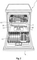
- Fig. 2 shows the dishwasher 1, especially the domestic dishwasher, in an exemplary loading position.
- the lower rack 4.1 is pulled out of the washing chamber 3 and rests on the door 6 of the dishwasher 1, whereas the upper rack 4.2 is slid into the washing chamber 3.
- Fig. 2 also shows that one end 29 of the lower spray arm 5.1 has an indicating element 7.
- indicating element 7 informs the user about the rotation of the lower spray arm 5.1. If the indicating element 7 changes position after the user has moved the lower rack 4.1 into the washing chamber 3 into its washing position, then the user can tell that the lower spray arm 4.1 is free to turn without any blockages and that proper movement of the lower spray arm 4.1 will be provided during the washing process of the dishes and the cutlery.
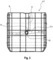
- Fig. 3 shows that the lower rack 4.1, and also the upper rack 4.2 (not shown; see Fig. 1 and 2 ), is constituted by multiple wires 8 crossing each other.
- the lower rack 4.1 has a checking mechanism 9.
- the checking mechanism 9 comprises a gear 10 and a gear rack 11.
- the gear rack 11 is hung on the wires 8 of the lower rack 4.1, preferably by means of clipping or snap fitting.
- the gear 10 is manufactured preferably in one piece (arrow) with the lower spray arm 4.1.
- the gear 10 has gear teeth 12 and the gear rack 11 has gear teeth 13 which engage by the sliding movement of the lower rack 4.1 into the washing chamber 3.
- the lower spray arm 5.1 starts to turn.
- the engagement between the gear 10 and the gear rack 11 is finalized.
- the gear 10 and the gear rack 11 do not touch each other or engage to one another.
- Fig. 6 shows that the gear rack 11 is linear.
- the gear rack 11 has gear rack teeth 13 and is hung to the wires 8 of the lower rack (not shown; see Fig. 3 ), preferably by means of clipping 14.
- Fig. 7 shows the gear 10 and the gear rack 11 in an engaged position.
- the gear teeth 12 of the gear 10 and the gear track teeth 13 of the gear rack 11 engage to each other during the sliding movement of the lower rack 4.1. This move turns the gear 10 and therefore the lower spray arm 5.1. After the lower rack 4.1 is fully slid into its place, the gear 10 and the gear rack 11 do not have any contact.
- Fig. 8 shows the dishwasher 1 in its loading position.
- the upper rack 4.2 which is constituted by multiple wires 15 crossing each other, is pushed out of the dishwasher 1.
- the upper rack 4.2 has a checking mechanism 9.
- a holder 16 (see also Fig. 9 ) is hung on the wire 15 of the upper rack 4.2, preferably by means of clipping 14 by at least one support element 17 (see also Fig. 9 ).
- the holder 16 can easily be removed by the user if wanted.
- the holder 16 comprises a first rod 18 and a second rod 19.
- the rods 18, 19 are connected to each other by a joint 20 (see also Fig. 9 ).
- One end of the first rod 18 comprises a linear gear 22 which engages to a gear 21 on the upper spray arm 5.2.
- the linear gear 22 comprises linear gear teeth 24 which engage to the gear teeth 23 of the gear 21.
- the end 30 of the second rod 19 does not touch to the back wall 25 of the dishwasher 1.
- Fig. 9 shows the upper rack 4.2 sliding into the dishwasher 1.
- the second rod 19 touches to the back wall 25 of the dishwasher 1 (see Fig. 8 ).
- the second rod 19 pushes the first rod 18 further into the direction towards the upper spray arm 5.2.
- the linear gear 22 and the gear 21 on the upper spray arm 5.2 are engaged.
- the force of this engagement turns the gear 21 and therefore the gear 21 turns the upper spray arm 5.2.
- the user checks if the free movement of the upper spray arm 5.2 is provided by checking the change of color on the either end 29 of the upper spray arm 5.2 (see Fig. 8 ).
- Fig. 10 shows the neural positon of the checking mechanism 9 as the spring 26 is not compressed when there is no sliding movement of the upper rack 4.2 into the dishwasher 1. In this position, the upper rack 4.2 is out of the dishwasher 1. The linear gear teeth 24 of the linear gear 22 and the gear teeth 23 of the gear 21 do not engage, as there is no force received from the first rod 18.
- the first rod 18 stays still inside the holder 16.
- a touching part 27 stabilizes the first rod 18.
- a touching part 27 also prevents the first rod 18 to move forward towards the opposite direction of the back wall 25 (see Fig. 8 ) so much so that the first rod 18 does not dislocate.
- the holder 16 comprises a protrusion 28 which engage to the touching part 27 to provide stabilization and balance for the first rod 18.
- Fig. 11 shows the engaged position of the checking mechanism 9.
- the second rod 19 touches the back wall 25 of the dishwasher 1.
- the second rod 19 which is connected to the first rod 18 by a joint 20 pushes the first rod 18 towards the opposite direction of the back wall 25.
- the spring 26 inside the holder 16 is compressed by the pushing force.
- the linear gear 22 on one end 30 of the first rod 18 is also moves to be in contact with the gear 21 which is located on the upper spray arm 5.2.
- the linear gear teeth 24 and the gear teeth 23 engage.
- the upper spray arm 5.2 starts to turn.
- the upper spray arm 5.2 turns around itself.
- the gear 21 and the linear gear 22 do not have any contact. The washing process runs without any blockages and interruptions.
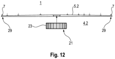
- Fig. 12 shows the spray arm 5.2 and the gear 21.
- the upper spray arm 5.2 and the gear 21 are preferably manufactured in one piece (arrow).
- the upper spray arm 5.2 is mounted to the upper rack 4.2.
- the gear 21 is attached to the substantial center of the upper spray arm 5.2.
- the gear 21 comprises gear teeth 23 which engage to the linear gear teeth 24 during the pushing movement of the upper rack 4.2 into the dishwasher 1 (see Figs. 10 and 11 ).
- the gear 21 receives force to turn the upper spray arm 5.2.
- the ends 29 of the upper spray arm 5.2 also turn and change position.
- the position change of the indicating element 7 or the color on either end 29 of the upper spray arm 5.2 informs the user of that there are no blockages for the upper spray arm 5.2 to turn freely. If there are blockages, the user can simply rearrange the dishes and/or cutlery.
Landscapes
- Washing And Drying Of Tableware (AREA)
Claims (14)
- Lave-vaisselle (1), en particulier lave-vaisselle domestique, comprenant une carrosserie (2), une chambre de lavage (3) disposée dans la carrosserie (2) dans laquelle le lavage est réalisé, au moins un râtelier (4.1, 4.2) qui est situé dans la chambre de lavage (3) pour charger de la vaisselle à laver et au moins un bras de pulvérisation (5.1, 5.2) qui tourne autour de lui-même et fournit de l'eau dans la chambre de lavage (3) pour laver la vaisselle,dans lequel le lave-vaisselle (1) comprend un mécanisme de vérification (9) qui est configuré pour transformer le mouvement de coulissement de l'au moins un râtelier (4.1, 4.2) en une rotation de l'au moins un bras de pulvérisation (5.1, 5.2),caractérisé en ce que le mécanisme de vérification (9) comprend au moins un engrenage (10, 21) disposé sur l'au moins un bras de pulvérisation (5.1, 5.2) et au moins de préférence une crémaillère à engrenage (11) ou un engrenage linéaire (22) agencé(e) sur l'au moins un râtelier (4.1, 4.2),dans lequel l'au moins de préférence une crémaillère à engrenage (11) ou un engrenage linéaire (22) met en prise l'au moins un engrenage (10, 21) et fait tourner l'au moins un bras de pulvérisation (5.1, 5.2) qui est couplé à l'au moins un engrenage (10, 21).
- Lave-vaisselle (1) selon la revendication 1, dans lequel l'au moins une crémaillère à engrenage (11) est située sur un râtelier inférieur (4.1).
- Lave-vaisselle (1) selon la revendication 1 ou 2, dans lequel l'au moins un engrenage (10) est situé sur un bras de pulvérisation inférieur (5.1) et/ou dans lequel l'au moins un engrenage (10) et un bras de pulvérisation inférieur (5.1) sont fabriqués d'une seule pièce.
- Lave-vaisselle (1) selon la revendication 1, 2 ou 3, dans lequel l'au moins un engrenage (10) et l'au moins une crémaillère à engrenage (11) sont positionnés de sorte qu'ils sont séparés pendant le processus de lavage.
- Lave-vaisselle (1) selon la revendication 1, dans lequel l'au moins une crémaillère à engrenage (11) est située sur un râtelier supérieur (4.2).
- Lave-vaisselle (1) selon la revendication 5, dans lequel un bras de pulvérisation supérieur (5.2) est monté directement sur le râtelier supérieur (4.2), de préférence par clippage (14).
- Lave-vaisselle (1) selon la revendication 5 ou 6, dans lequel un bras de pulvérisation supérieur (5.2) comprend au moins un engrenage (20) positionné dans un centre substantiel d'un bras de pulvérisation supérieur (5.2) et/ou dans lequel un bras de pulvérisation supérieur (5.2) et l'au moins une crémaillère à engrenage (20) sont fabriqués en une seule pièce.
- Lave-vaisselle (1) selon la revendication 5, 6 ou 7, dans lequel le mécanisme de vérification (9) comprend un support (16) qui est fixé au râtelier supérieur (4.2) par au moins un élément de support (17).
- Lave-vaisselle (1) selon la revendication 8, dans lequel le support (16) comprend une première tige (18) qui est déplacée par le déplacement d'une deuxième tige (19).
- Lave-vaisselle (1) selon la revendication 9, dans lequel la première tige (18) comprend en outre un engrenage linéaire (22) sur au moins une extrémité et/ou dans lequel le support (16) comprend un ressort (26) configuré pour déplacer la première tige (18).
- Lave-vaisselle (1) selon la revendication 9 ou 10, dans lequel le support (16) comprend la deuxième tige (19) qui connecte la première tige (18) par un raccord (20).
- Lave-vaisselle (1) selon les revendications 8 à 11, dans lequel le support (16) est fixé au râtelier supérieur (4.2), de préférence par clippage (14).
- Lave-vaisselle (1) selon l'une quelconque des revendications précédentes, dans lequel au moins une extrémité de l'au moins un bras de pulvérisation (5.1, 5.2) comprend au moins un élément indicateur (7).
- Lave-vaisselle (1) selon la revendication 13, dans lequel l'élément indicateur (7) est fixé par encliquetage, dans lequel l'élément indicateur (7) et l'au moins un bras de pulvérisation (5.1, 5.2) sont fabriqués de préférence en une seule pièce et/ou dans lequel l'élément indicateur (7) est collé à au moins une extrémité de l'au moins un bras de pulvérisation (5.1, 5.2).
Applications Claiming Priority (3)
| Application Number | Priority Date | Filing Date | Title |
|---|---|---|---|
| TR2019/16591A TR201916591A2 (tr) | 2019-10-25 | 2019-10-25 | A dishwasher comprising a checking mechanism |
| TR2020/10271A TR202010271A2 (fr) | 2019-10-25 | 2020-06-30 | |
| PCT/EP2020/079463 WO2021078718A1 (fr) | 2019-10-25 | 2020-10-20 | Lave-vaisselle |
Publications (2)
| Publication Number | Publication Date |
|---|---|
| EP4048129A1 EP4048129A1 (fr) | 2022-08-31 |
| EP4048129B1 true EP4048129B1 (fr) | 2025-06-18 |
Family
ID=73005606
Family Applications (1)
| Application Number | Title | Priority Date | Filing Date |
|---|---|---|---|
| EP20796533.6A Active EP4048129B1 (fr) | 2019-10-25 | 2020-10-20 | Lave-vaisselle |
Country Status (4)
| Country | Link |
|---|---|
| US (1) | US12114827B2 (fr) |
| EP (1) | EP4048129B1 (fr) |
| CN (1) | CN114599261B (fr) |
| WO (1) | WO2021078718A1 (fr) |
Families Citing this family (2)
| Publication number | Priority date | Publication date | Assignee | Title |
|---|---|---|---|---|
| DE102021212933A1 (de) * | 2021-11-17 | 2023-05-17 | BSH Hausgeräte GmbH | Haushalts-Geschirrspülmaschine |
| DE102022206488A1 (de) | 2022-06-28 | 2023-12-28 | BSH Hausgeräte GmbH | Haushalts-Geschirrspülmaschine |
Family Cites Families (13)
| Publication number | Priority date | Publication date | Assignee | Title |
|---|---|---|---|---|
| DE1291869B (de) * | 1967-08-29 | 1969-04-03 | Bosch Hausgeraete Gmbh | Spritzvorrichtung fuer eine Geschirrspuelmaschine |
| US4175575A (en) * | 1978-03-27 | 1979-11-27 | General Electric Company | Dishwasher with oscillating rotary spray arm |
| DE3732451A1 (de) * | 1987-09-25 | 1989-04-20 | Bosch Siemens Hausgeraete | Geschirrspuelmaschine mit einer einrichtung zur ueberwachung der drehbewegung des sprueharmes |
| DE4018048A1 (de) * | 1990-06-06 | 1991-12-12 | Licentia Gmbh | Geschirrspuelmaschine |
| US8113222B2 (en) | 2008-12-16 | 2012-02-14 | Whirlpool Corporation | Dishwasher with driven spray arm for upper rack |
| US8191560B2 (en) * | 2009-06-11 | 2012-06-05 | General Electric Company | Adjustable upper dishwasher rack |
| DE102009028035A1 (de) * | 2009-07-27 | 2011-02-03 | BSH Bosch und Siemens Hausgeräte GmbH | Haushaltsgeschirrspülmaschine |
| CA2768060C (fr) * | 2009-08-10 | 2016-07-12 | Electrolux Home Products, Inc. | Agencement de circulation de fluide permettant de fournir un effet de lavage intensifie dans un lave-vaisselle, et procede associe |
| US20120285496A1 (en) * | 2011-05-09 | 2012-11-15 | General Electric Company | Dishwasher spray assembly |
| CA2850110C (fr) | 2011-11-04 | 2017-08-22 | Arcelik Anonim Sirketi | Lave-vaisselle |
| AU2014304747B2 (en) * | 2013-08-06 | 2016-11-03 | Arcelik Anonim Sirketi | A dishwasher with improved washing effectiveness |
| US10292564B2 (en) * | 2015-11-17 | 2019-05-21 | Haier Us Appliance Solutions, Inc. | Spray arm assemblies for dishwasher appliances |
| US20170224190A1 (en) * | 2016-02-05 | 2017-08-10 | General Electric Company | Dishwasher Rack Lift Mechanism |
-
2020
- 2020-10-20 WO PCT/EP2020/079463 patent/WO2021078718A1/fr not_active Ceased
- 2020-10-20 CN CN202080074206.2A patent/CN114599261B/zh active Active
- 2020-10-20 US US17/762,754 patent/US12114827B2/en active Active
- 2020-10-20 EP EP20796533.6A patent/EP4048129B1/fr active Active
Also Published As
| Publication number | Publication date |
|---|---|
| CN114599261B (zh) | 2024-04-12 |
| WO2021078718A1 (fr) | 2021-04-29 |
| EP4048129A1 (fr) | 2022-08-31 |
| US20220354338A1 (en) | 2022-11-10 |
| US12114827B2 (en) | 2024-10-15 |
| CN114599261A (zh) | 2022-06-07 |
Similar Documents
| Publication | Publication Date | Title |
|---|---|---|
| EP2292140A1 (fr) | Conteneur pour couverts, spécialement un plateau et/ou panier pour couverts, ainsi qu'un lave-vaisselle avec un tel conteneur pour couverts | |
| ES2310345T3 (es) | Lavavajillas. | |
| EP4048129B1 (fr) | Lave-vaisselle | |
| EP2723226B1 (fr) | Un lave-vaisselle | |
| EP2818092A1 (fr) | Lave-vaisselle | |
| KR102512217B1 (ko) | 식기세척기 | |
| EP2191764A1 (fr) | Panier de lave-vaisselle avec support de coupe | |
| KR20160141787A (ko) | 가구 또는 가전 제품 일부의 선반의 슬라이딩/피봇 장치, 이를 포함하는 가전 제품 및 가구의 부분 | |
| KR20210137571A (ko) | 가구 또는 가정용 기기의 선반용 슬라이딩-회동 기구 및 가구 또는 가정용 기기 | |
| CN114630610B (zh) | 洗碗机 | |
| JP2006262923A (ja) | 食器洗い機 | |
| KR20200055460A (ko) | 랙 어셈블리 및 이를 갖는 식기세척기 | |
| EP1286616B1 (fr) | Panier de lave-vaisselle et corbeilles de retenue pliables pour la vaisselle | |
| EP0855166B1 (fr) | Panier extractible pour lave vaisselle | |
| EP3302211B1 (fr) | Accessoire de lavage de bouteille destiné à être utilisé sur le support d'article d'un lave-vaisselle | |
| KR102034581B1 (ko) | 식기세척기의 랙 | |
| JP4770573B2 (ja) | 食器洗浄機 | |
| JP4273251B2 (ja) | 食器洗浄機 | |
| EP4578370A1 (fr) | Lave-vaisselle comprenant des fils mobiles | |
| JP2006043183A (ja) | 食器洗い機 | |
| CN217090415U (zh) | 烹饪器具 | |
| CN102197980A (zh) | 一种带有额外筐子的洗碗机 | |
| US20230287620A1 (en) | Ergonomically designed household appliances for individuals with limited mobility | |
| JP4720591B2 (ja) | 食器洗い機 | |
| JP2006081803A (ja) | 食器洗い機 |
Legal Events
| Date | Code | Title | Description |
|---|---|---|---|
| STAA | Information on the status of an ep patent application or granted ep patent |
Free format text: STATUS: UNKNOWN |
|
| STAA | Information on the status of an ep patent application or granted ep patent |
Free format text: STATUS: THE INTERNATIONAL PUBLICATION HAS BEEN MADE |
|
| PUAI | Public reference made under article 153(3) epc to a published international application that has entered the european phase |
Free format text: ORIGINAL CODE: 0009012 |
|
| STAA | Information on the status of an ep patent application or granted ep patent |
Free format text: STATUS: REQUEST FOR EXAMINATION WAS MADE |
|
| 17P | Request for examination filed |
Effective date: 20220525 |
|
| AK | Designated contracting states |
Kind code of ref document: A1 Designated state(s): AL AT BE BG CH CY CZ DE DK EE ES FI FR GB GR HR HU IE IS IT LI LT LU LV MC MK MT NL NO PL PT RO RS SE SI SK SM TR |
|
| DAV | Request for validation of the european patent (deleted) | ||
| DAX | Request for extension of the european patent (deleted) | ||
| GRAP | Despatch of communication of intention to grant a patent |
Free format text: ORIGINAL CODE: EPIDOSNIGR1 |
|
| STAA | Information on the status of an ep patent application or granted ep patent |
Free format text: STATUS: GRANT OF PATENT IS INTENDED |
|
| RIC1 | Information provided on ipc code assigned before grant |
Ipc: A47L 15/23 20060101ALN20250130BHEP Ipc: A47L 15/50 20060101ALI20250130BHEP Ipc: A47L 15/00 20060101AFI20250130BHEP |
|
| INTG | Intention to grant announced |
Effective date: 20250218 |
|
| GRAS | Grant fee paid |
Free format text: ORIGINAL CODE: EPIDOSNIGR3 |
|
| GRAA | (expected) grant |
Free format text: ORIGINAL CODE: 0009210 |
|
| STAA | Information on the status of an ep patent application or granted ep patent |
Free format text: STATUS: THE PATENT HAS BEEN GRANTED |
|
| AK | Designated contracting states |
Kind code of ref document: B1 Designated state(s): AL AT BE BG CH CY CZ DE DK EE ES FI FR GB GR HR HU IE IS IT LI LT LU LV MC MK MT NL NO PL PT RO RS SE SI SK SM TR |
|
| REG | Reference to a national code |
Ref country code: GB Ref legal event code: FG4D |
|
| REG | Reference to a national code |
Ref country code: CH Ref legal event code: EP |
|
| REG | Reference to a national code |
Ref country code: DE Ref legal event code: R096 Ref document number: 602020052997 Country of ref document: DE |
|
| REG | Reference to a national code |
Ref country code: CH Ref legal event code: EP |
|
| REG | Reference to a national code |
Ref country code: IE Ref legal event code: FG4D |
|
| PG25 | Lapsed in a contracting state [announced via postgrant information from national office to epo] |
Ref country code: FI Free format text: LAPSE BECAUSE OF FAILURE TO SUBMIT A TRANSLATION OF THE DESCRIPTION OR TO PAY THE FEE WITHIN THE PRESCRIBED TIME-LIMIT Effective date: 20250618 |
|
| REG | Reference to a national code |
Ref country code: LT Ref legal event code: MG9D |
|
| PG25 | Lapsed in a contracting state [announced via postgrant information from national office to epo] |
Ref country code: NO Free format text: LAPSE BECAUSE OF FAILURE TO SUBMIT A TRANSLATION OF THE DESCRIPTION OR TO PAY THE FEE WITHIN THE PRESCRIBED TIME-LIMIT Effective date: 20250918 Ref country code: GR Free format text: LAPSE BECAUSE OF FAILURE TO SUBMIT A TRANSLATION OF THE DESCRIPTION OR TO PAY THE FEE WITHIN THE PRESCRIBED TIME-LIMIT Effective date: 20250919 |
|
| PG25 | Lapsed in a contracting state [announced via postgrant information from national office to epo] |
Ref country code: BG Free format text: LAPSE BECAUSE OF FAILURE TO SUBMIT A TRANSLATION OF THE DESCRIPTION OR TO PAY THE FEE WITHIN THE PRESCRIBED TIME-LIMIT Effective date: 20250618 |
|
| PG25 | Lapsed in a contracting state [announced via postgrant information from national office to epo] |
Ref country code: HR Free format text: LAPSE BECAUSE OF FAILURE TO SUBMIT A TRANSLATION OF THE DESCRIPTION OR TO PAY THE FEE WITHIN THE PRESCRIBED TIME-LIMIT Effective date: 20250618 |
|
| PG25 | Lapsed in a contracting state [announced via postgrant information from national office to epo] |
Ref country code: RS Free format text: LAPSE BECAUSE OF FAILURE TO SUBMIT A TRANSLATION OF THE DESCRIPTION OR TO PAY THE FEE WITHIN THE PRESCRIBED TIME-LIMIT Effective date: 20250918 |
|
| REG | Reference to a national code |
Ref country code: NL Ref legal event code: MP Effective date: 20250618 |
|
| PG25 | Lapsed in a contracting state [announced via postgrant information from national office to epo] |
Ref country code: LV Free format text: LAPSE BECAUSE OF FAILURE TO SUBMIT A TRANSLATION OF THE DESCRIPTION OR TO PAY THE FEE WITHIN THE PRESCRIBED TIME-LIMIT Effective date: 20250618 |
|
| PG25 | Lapsed in a contracting state [announced via postgrant information from national office to epo] |
Ref country code: NL Free format text: LAPSE BECAUSE OF FAILURE TO SUBMIT A TRANSLATION OF THE DESCRIPTION OR TO PAY THE FEE WITHIN THE PRESCRIBED TIME-LIMIT Effective date: 20250618 |
|
| PG25 | Lapsed in a contracting state [announced via postgrant information from national office to epo] |
Ref country code: PT Free format text: LAPSE BECAUSE OF FAILURE TO SUBMIT A TRANSLATION OF THE DESCRIPTION OR TO PAY THE FEE WITHIN THE PRESCRIBED TIME-LIMIT Effective date: 20251020 |
|
| REG | Reference to a national code |
Ref country code: AT Ref legal event code: MK05 Ref document number: 1803424 Country of ref document: AT Kind code of ref document: T Effective date: 20250618 |
|
| PG25 | Lapsed in a contracting state [announced via postgrant information from national office to epo] |
Ref country code: IS Free format text: LAPSE BECAUSE OF FAILURE TO SUBMIT A TRANSLATION OF THE DESCRIPTION OR TO PAY THE FEE WITHIN THE PRESCRIBED TIME-LIMIT Effective date: 20251018 |
|
| PGFP | Annual fee paid to national office [announced via postgrant information from national office to epo] |
Ref country code: DE Payment date: 20251031 Year of fee payment: 6 |
|
| PG25 | Lapsed in a contracting state [announced via postgrant information from national office to epo] |
Ref country code: AT Free format text: LAPSE BECAUSE OF FAILURE TO SUBMIT A TRANSLATION OF THE DESCRIPTION OR TO PAY THE FEE WITHIN THE PRESCRIBED TIME-LIMIT Effective date: 20250618 Ref country code: SM Free format text: LAPSE BECAUSE OF FAILURE TO SUBMIT A TRANSLATION OF THE DESCRIPTION OR TO PAY THE FEE WITHIN THE PRESCRIBED TIME-LIMIT Effective date: 20250618 |
|
| PG25 | Lapsed in a contracting state [announced via postgrant information from national office to epo] |
Ref country code: CZ Free format text: LAPSE BECAUSE OF FAILURE TO SUBMIT A TRANSLATION OF THE DESCRIPTION OR TO PAY THE FEE WITHIN THE PRESCRIBED TIME-LIMIT Effective date: 20250618 |
|
| PG25 | Lapsed in a contracting state [announced via postgrant information from national office to epo] |
Ref country code: PL Free format text: LAPSE BECAUSE OF FAILURE TO SUBMIT A TRANSLATION OF THE DESCRIPTION OR TO PAY THE FEE WITHIN THE PRESCRIBED TIME-LIMIT Effective date: 20250618 |
|
| PG25 | Lapsed in a contracting state [announced via postgrant information from national office to epo] |
Ref country code: EE Free format text: LAPSE BECAUSE OF FAILURE TO SUBMIT A TRANSLATION OF THE DESCRIPTION OR TO PAY THE FEE WITHIN THE PRESCRIBED TIME-LIMIT Effective date: 20250618 |
|
| PG25 | Lapsed in a contracting state [announced via postgrant information from national office to epo] |
Ref country code: SK Free format text: LAPSE BECAUSE OF FAILURE TO SUBMIT A TRANSLATION OF THE DESCRIPTION OR TO PAY THE FEE WITHIN THE PRESCRIBED TIME-LIMIT Effective date: 20250618 |
|
| PG25 | Lapsed in a contracting state [announced via postgrant information from national office to epo] |
Ref country code: ES Free format text: LAPSE BECAUSE OF FAILURE TO SUBMIT A TRANSLATION OF THE DESCRIPTION OR TO PAY THE FEE WITHIN THE PRESCRIBED TIME-LIMIT Effective date: 20250618 |
|
| PG25 | Lapsed in a contracting state [announced via postgrant information from national office to epo] |
Ref country code: RO Free format text: LAPSE BECAUSE OF FAILURE TO SUBMIT A TRANSLATION OF THE DESCRIPTION OR TO PAY THE FEE WITHIN THE PRESCRIBED TIME-LIMIT Effective date: 20250618 |
|
| PG25 | Lapsed in a contracting state [announced via postgrant information from national office to epo] |
Ref country code: DK Free format text: LAPSE BECAUSE OF FAILURE TO SUBMIT A TRANSLATION OF THE DESCRIPTION OR TO PAY THE FEE WITHIN THE PRESCRIBED TIME-LIMIT Effective date: 20250618 |
|
| PG25 | Lapsed in a contracting state [announced via postgrant information from national office to epo] |
Ref country code: IT Free format text: LAPSE BECAUSE OF FAILURE TO SUBMIT A TRANSLATION OF THE DESCRIPTION OR TO PAY THE FEE WITHIN THE PRESCRIBED TIME-LIMIT Effective date: 20250618 |
|
| PLBE | No opposition filed within time limit |
Free format text: ORIGINAL CODE: 0009261 |
|
| STAA | Information on the status of an ep patent application or granted ep patent |
Free format text: STATUS: NO OPPOSITION FILED WITHIN TIME LIMIT |
|
| REG | Reference to a national code |
Ref country code: CH Ref legal event code: L10 Free format text: ST27 STATUS EVENT CODE: U-0-0-L10-L00 (AS PROVIDED BY THE NATIONAL OFFICE) Effective date: 20260430 |