EP4048414B1 - Appareil de terrain de jeu - Google Patents
Appareil de terrain de jeu Download PDFInfo
- Publication number
- EP4048414B1 EP4048414B1 EP20792984.5A EP20792984A EP4048414B1 EP 4048414 B1 EP4048414 B1 EP 4048414B1 EP 20792984 A EP20792984 A EP 20792984A EP 4048414 B1 EP4048414 B1 EP 4048414B1
- Authority
- EP
- European Patent Office
- Prior art keywords
- platform
- lever portion
- assembly
- spring
- disposed
- Prior art date
- Legal status (The legal status is an assumption and is not a legal conclusion. Google has not performed a legal analysis and makes no representation as to the accuracy of the status listed.)
- Active
Links
Images




Classifications
-
- A—HUMAN NECESSITIES
- A63—SPORTS; GAMES; AMUSEMENTS
- A63B—APPARATUS FOR PHYSICAL TRAINING, GYMNASTICS, SWIMMING, CLIMBING, OR FENCING; BALL GAMES; TRAINING EQUIPMENT
- A63B9/00—Climbing poles, frames, or stages
-
- A—HUMAN NECESSITIES
- A63—SPORTS; GAMES; AMUSEMENTS
- A63B—APPARATUS FOR PHYSICAL TRAINING, GYMNASTICS, SWIMMING, CLIMBING, OR FENCING; BALL GAMES; TRAINING EQUIPMENT
- A63B5/00—Apparatus for jumping
- A63B5/06—Vaulting poles ; Take-off boxes therefor
-
- A—HUMAN NECESSITIES
- A63—SPORTS; GAMES; AMUSEMENTS
- A63B—APPARATUS FOR PHYSICAL TRAINING, GYMNASTICS, SWIMMING, CLIMBING, OR FENCING; BALL GAMES; TRAINING EQUIPMENT
- A63B9/00—Climbing poles, frames, or stages
- A63B2009/006—Playground structures
-
- A—HUMAN NECESSITIES
- A63—SPORTS; GAMES; AMUSEMENTS
- A63B—APPARATUS FOR PHYSICAL TRAINING, GYMNASTICS, SWIMMING, CLIMBING, OR FENCING; BALL GAMES; TRAINING EQUIPMENT
- A63B2208/00—Characteristics or parameters related to the user or player
- A63B2208/12—Characteristics or parameters related to the user or player specially adapted for children
Definitions
- the present disclosure generally relates to a playground apparatus. More specifically, the disclosure relates to a playground apparatus which simulates a pole-vaulting activity for children to play.
- crows nest apparatus are quite complicated and require a flexible post which can have a reduced lifetime and/or a risk of breakage.
- a complicated mechanism is proposed to control the motion of the pole.
- crows nests need to be placed far from other apparatus so that the crows nest does not come into contact with other play apparatus.
- the crows nest apparatus is an apparatus which is a standalone activity and is not a part of a greater activity.
- a first aspect of the current invention is therefore to provide a playground apparatus which is a fun apparatus for children to play on.
- a second aspect of the current invention is to provide a playground apparatus which has a simple assembly with a robust construction.
- a third aspect of the current invention is to provide a playground apparatus which can be integrated into a larger playground concept.
- a playground apparatus is provided whereby a child can move him or herself from a first platform assembly to a second platform assembly as part of their travel around a playground.
- the motion occurs at a significant height above the ground giving a great feeling of flying.
- the safety of the apparatus is also high.
- the first platform assembly includes a first climbing structure to facilitate a climbing between the surface and the first platform structure
- the second platform assembly includes a second climbing structure to facilitate a climbing between the surface and the second platform structure
- each of the first platform structure and the second platform structure is disposed at an inclination relative to the surface. In one embodiment, the first platform structure and the second platform structure form an angle of greater than 10, greater than 15 or greater than 20 degrees to the surface. In one embodiment, the first platform structure and the second platform structure form an angle of less than 60, less than 50 or less than 40 degrees to the surface.
- the first and second platform structures are arranged so that the two platforms face each other and such that the angle A between the normal vectors to the surfaces of the first and second platforms is less than 100 degrees, less than 90 degrees or less than 80 degrees. In one embodiment, the angle A is greater than 10 degrees, greater than 20 degrees or greater than 30 degrees. In one embodiment, the normal vectors to the surfaces of the first and second platforms each have a component in the upwards direction.
- the playground apparatus includes a spring assembly for biasing the lever portion to a central position.
- the lever structure in the central position, is disposed substantially perpendicularly to the surface.
- the spring assembly includes a first spring coupled between the lever portion and one of the first platform assembly or the surface, and/or a second spring coupled between the lever portion and one of the second platform assembly or the surface.
- the spring assembly includes a first spring coupled to the lever portion and/or a second spring coupled to the lever portion.
- the first spring is a torsional spring and/or the second spring is a torsional spring.
- the playground apparatus includes a spring assembly for biasing the lever portion towards the second position.
- the damping assembly and/or the spring assembly comprises a torsional damping element and/or a torsional spring element.
- a ROSTA type element is used to combine both damping and spring properties.
- the playground apparatus further includes a damping assembly for damping a movement of the lever portion.
- the pole structure includes a base portion attached to the surface and supporting the lever portion.
- the lever portion is adapted to pivot relative to the base portion.
- the base portion and/or the lever portion includes an upright structure and at least one safety structure extending downwardly at an inclination relative to the upright structure.
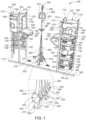
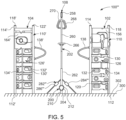
- the playground apparatus 100 includes a first platform assembly 102, a second platform assembly 104 disposed spaced apart from the first platform assembly 102, and a pole structure 108 disposed between the first platform assembly 102 and the second platform assembly 104.
- the first platform assembly 102 is supported by a surface 300, such as a ground surface 302, and extends upwardly from the surface 300.
- the first platform assembly 102 includes an upright structure 110 adapted to extend substantially perpendicularly from the surface 300 and has a first end 112 in contact with the surface 300 and a second end 114 disposed away from the surface 300.
- the upright structure 110 is a self-standing structure and may include a plurality of pillars, for example, a first pillar 118, a second pillar 120, and a third pillar 122, disposed spaced apart from each other and arrayed circularly for enabling a positioning of the upright structure 110 on the surface 300.
- the pillars 118, 120, 122 extends upwardly in a vertical direction from the surface 300.
- the upright structure 110 further includes a climbing structure 126 (also referred to as a first climbing structure 126) having a plurality of panels 130 disposed spaced apart from each other and arrayed linearly in a vertical direction from the first end 112 towards the second end 114.
- each panel 130 extends between the two pillars, for example, the first pillar 118 and the second pillar 120, and may be coupled/attached to the pillars 118, 120.
- each panel 130 may include at least one opening, for example, a first opening 132 and a second opening 134 horizontally spaced from the first opening 134, for providing hand and/or foot holes to facilitate a climbing up and down of a child.
- the first opening 132 may include an oval shape, while the second opening 134 may include a circular shape. In an embodiment, a shape of the first opening 132 may be the same as the shape of the second opening 134.
- the first climbing structure 126 having the plurality of panels 130 is contemplated, it may be appreciated that the first climbing structure 126 may include a single panel. In such a case, the panel may include a plurality of openings and/or protrusions, for example climbing grips, arrayed along a height of the panel and disposed spaced from each other. The plurality of openings/protrusions may define the plurality of steps of the first climbing structure. Other climbing options could also be imagined, for example a climbing rope, a ladder with ordinary rungs, a fireman's pole, etc.
- the first platform assembly 102 further includes a first platform structure 138 disposed at a vertical distance (i.e. vertically spaced) from the surface 300, and is coupled to the two pillars, for example, the second pillar 120 and the third pillar 122. As shown, the first platform structure 138 extends outwardly from the pillars 120, 122 in a direction away from the upright structure 110 and towards the pole structure 108. In an embodiment, the first platform structure 138 is substantially parallel to the surface 300. In certain embodiments, the platform structure 138 may be disposed at an inclination relative to the surface 300 and the pillars 120, 122.
- the first platform structure 138 includes a first end 140 coupled/attached/engaged with the pillars 120, 122 (i.e. the upright structure 110), and a second end 142 disposed downwardly from the first end 140 and located distally from the upright structure 110. Accordingly, an upper surface of the first platform structure 138 defines an acute angle 'A' of inclination relative to the pillars 120, 122. In an embodiment, the angle 'A' may be in a range between twenty five degrees to forty five degrees. In an implementation, the angle 'A' may be thirty degrees. An inclination of the first platform structure 138 relative to the surface 300 or the upright structure 110 (i.e. the pillars 120, 122) may discourage children from sitting on the first platform structure 138 and using it as a more permanent resting place.
- the first platform assembly 102 further includes a support platform 150 disposed substantially parallel to the surface 300 and located between the pillars 118, 120, 122 and connected to the pillars 118, 120, 122. Further, the support platform 150 is positioned between the second end 114 of the upright structure 110 and the first climbing structure 126 such that the support platform 150 and the first end 140 of the first platform structure 138 may be disposed at substantially the same height from the surface 300. In this manner, children can safely and easily move between the support platform 150 and the first platform structure 138. Further, the support platform 150 may include a plurality of holes 152 to facilitate a passage of snow or dirt therethrough, thereby preventing an accumulation of snow or dirt on the support platform 150.
- the first platform assembly 102 may include a gate 156 for allowing and/or preventing an access of the support platform 150 from the first climbing structure 126 or vice versa via an access opening 158 defined between the first pillar 118, the second pillar 120, and the support platform 150.
- the gate 156 may include a first end pivotably coupled to the second pillar 120 and adapted to pivot about an axis 160 substantially parallel to the second pillar 120 for opening and closing the access opening 158.
- the gate 156 may be attached to the second pillar 120 via a hinge assembly 162.
- the plate 156 shown in the figures is fixed in position and cannot pivot out. As such, children can enter the upper portion of the first platform assembly via the opening 158.
- the first platform assembly 102 may include a first rail 164 disposed above the support platform 150 and extending from the first pillar 118 to the third pillar 122. Also, the first platform assembly 102 may include an access window 170 defined between the second pillar 120 and the third pillar 122 to facilitate a movement of the children between the first platform structure 138 and the support platform 150.
- a second rail 172 may be disposed between the second pillar 120 and the third pillar 122 covering, partly, the access window 170. As shown, the second rail 172 may be disposed above the support platform 150 and may extend from the second pillar 120 towards the third pillar 122. The second rail 172 provides a support to the children during transitioning from the first platform structure 138 to the pole structure 108.
- the second platform assembly 104 is disposed horizontally spaced from the first platform assembly 102 and extends upwardly from the surface 300.
- the second platform assembly 104 is similar in structure, construction, assembly, and function to that of the first platform assembly 102. Further, structure, construction, attachment and functions of various components, sub-assemblies, structures of the second platform assembly 104 are same as the structure, attachment, construction, and functions of the corresponding components, sub-assemblies, structures, etc., of the first platform assembly 102 unless otherwise specified.
- the second platform assembly 104 includes an upright structure 110' having a first end 112', a second end 114', a plurality of pillars, for example, a first pillar 118', a second pillar 120', and a third pillar 122', a climbing structure 126' (also referred to as a second climbing structure 126'), a plurality of panels 130', each panel having a pair of openings 132', 134'.
- the second platform assembly 104 further includes a platform structure 138' (also referred to as a second platform structure 138') having a first end 140' and a second end 142', a support platform 150' having a plurality of holes 152', an access opening 158', a gate 156', an axis, a hinge assembly, a first rail 164', a second rail 172', and an access window 170' facilitate a movement of the children between the second platform structure 138' and the pole structure 108.
- a platform structure 138' also referred to as a second platform structure 138'
- a support platform 150' having a plurality of holes 152', an access opening 158', a gate 156', an axis, a hinge assembly, a first rail 164', a second rail 172', and an access window 170' facilitate a movement of the children between the second platform structure 138' and the pole structure 108.
- the pole structure 108 extends upwardly from the surface 300 and includes a base portion 200 attached/coupled to surface 300, and a lever portion 202 pivotally engaged/attached to the base portion 202 and extending upwardly from the base portion 200.
- the base portion 200 includes an upright structure 204 extending upwardly from the surface 300 and having a first end 206 attached to the surface 300 and a second end 208 coupled to the lever portion 202.
- the upright structure 204 may include an elongated portion 210 extending substantially vertically upwardly from the surface 300, and an engagement portion 212 extending from the elongated portion 210 to the second end 208 of the upright structure 204.
- the engagement portion 212 may be adapted to partially receive the lever portion 202, and may be pivotally coupled with the lever portion 202.
- the lever portion 202 is adapted to pivot about a pivot axis 220 that is substantially parallel to the surface 300.
- the lever portion 202 is adapted or arranged to pivot between a first position and a second position.
- the engagement portion 212 may include at least two members extending upwardly from a base member 222 and disposed spaced apart from each other to define at least one cavity to receive the lever portion 202.
- the engagement portion 212 may include four members, for example, a first member 224, a second member 226, a third member 228, and a fourth member 230 defining three cavities, for example, a first cavity 232, a second cavity 234, and a third cavity 236, therebetween to receive the lever portion 202.
- the members 224, 226, 228, 230 are arranged in such a manner that the members 224, 226, 228, 230 facilitate the pivoting of the lever portion 202 about the pivot axis 220, while substantially restricting the pivoting of the lever portion 202 about an axis that is parallel to the surface 300 and at an angle to the pivot axis 220.
- the pole structure for example, the base portion 200 (as shown in FIG. 3 ) may include at least one safety structure 250 to facilitate a safe landing of the children to the surface 300 in the case that a child falls off the pole structure.
- the safety structure 250 may extend circularly around the elongated portion 210. In such a case, the safety structure 250 may completely surround the elongated portion 210.
- the safety structure 250 includes a first end 252 connected to the upright structure 204 and a second end 254 disposed proximate or abutting the surface 300.
- the safety structure 250 is arranged in such a manner that a surface 248 of the safety structure 250 extends downwardly towards the surface 300 at an inclination relative to the upright structure 204, thereby facilitating a sliding of the children, should they fall from the structure, to the surface 300.
- an angle of inclination between the safety structure 250 and the upright structure 204 i.e. the elongated portion 210) may be an acute angle.
- the base portion 200 may include more than one safety structure. In such a case, the safety structures may be circularly arrayed around the elongated portion 210.
- the lever portion 202 may include first end 256, a second end 258, and a pole 260 extending from the first end 256 to the second end 258.
- the lever portion is adapted to pivot between a first position and a second position about an axis 220 which is parallel to the surface 300.
- An end of the pole 260 is pivotally coupled to the engagement portion 212 (i.e. the base portion 200), while another end of the pole 260 is a free end. Further, as shown in FIG.
- the lever portion 202 may include two side levers, for example, a first side lever 262 and a second side lever 264, respectively disposed on each side of the pole 260 such that an end of the first side lever 262 and an end of second side lever 264 are connected to the pole 260, while respective other ends of the side levers 262, 264 are received within the first cavity 232 and the third cavity 236. Therefore, the side levers 262, 264 extend from the engagement portion 212 to the pole 260. In this manner, the side levers 262, 264 provide additional rigidity and support to the lever portion 202.
- the lever portion 202 includes at least one support structure 266 for supporting one or more children.
- the support structure 266 is a plate disposed circularly around the pole 260 and extending radially outwardly from the pole 260 and may be disposed proximate to the second end 258 of the lever portion 202.
- a height of the support structure 266 from the surface 300 when in the first or second position may be substantially equal to a height of the first platform structure 138 and/or a height of the second platform structure 138' from the surface 300 to facilitate an easy movement of the children between the support structure 266 and the platform assemblies 102, 104.
- the support structure 266 may include a plurality of holes (not shown) to prevent an accumulation of snow or dirt on a surface of the support structure 266.
- the lever portion 202 may include a plurality of support structures, for example, two support structures disposed spaced apart and arrayed circularly around the pole 260.
- the lever portion 202 may include at least one handle, for example a first handle 268 and a second handle 270, extending outwardly from the pole 260 and disposed between the support structure 266 and the second end 258.
- the handles 268, 270 are adapted to be held by the children when the children are standing on the support structure 266.
- the playground apparatus 100 may include a spring assembly 274 for biasing the lever portion 202 to a central position between the first and second positions.
- the lever portion 202 In the central position, the lever portion 202 is disposed substantially perpendicularly to the surface. While in the first position, the lever portion 202 is positioned at an inclination to the surface 300 such that the support structure 266 is disposed proximate to the first platform structure 138. Further, in the second position, the lever portion 202 is positioned/arranged at an inclination to the surface 300 such that the support structure 266 is disposed proximate to the second platform structure 138'.
- the spring assembly 274 may include a first spring 276 extending from the lever portion 202 towards the first platform assembly 102 and connected to the surface 300 or to the first platform assembly 102, and a second spring 278 extending from the lever portion 202 towards the second platform assembly 104 and connected to the surface 300 or to the second platform assembly 104.
- a first spring 276 extending from the lever portion 202 towards the first platform assembly 102 and connected to the surface 300 or to the first platform assembly 102
- a second spring 278 extending from the lever portion 202 towards the second platform assembly 104 and connected to the surface 300 or to the second platform assembly 104.
- an end of the first spring 276 is connected to the lever portion 202 and another end of the first spring 276 is connected to the surface 300.
- an end of the second spring 278 is connected to the lever portion 202, while another end of the second spring 278 is connected to the surface 300.
- the first spring 276 and the second spring 278 together apply a force on the lever portion 202 (i.e.
- the pole 260 to return the lever portion 202 (i.e. the pole 260) towards the central position as the lever portion 202 pivots/moves away from the central position either towards the first position or towards the second position.
- one of the first spring 276 and the second spring 278 may be omitted, and in such a case, the spring assembly 274 may include a single spring.
- FIG. 6 and 7 shows a more detailed embodiment of a combined spring and damper assembly.
- a playground apparatus 100" is shown according to an alternative embodiment of the disclosure.
- a structure and construction of the playground apparatus 100" is similar to a structure and construction of the playground apparatus 100 apart from a structure, construction, and an attachment of the spring assembly. Further, the elements of the playground apparatus 100" having similar constructional and structural aspects as that of the elements of the playground apparatus 100 will have same reference numerals.
- the playground apparatus 100" may include a spring assembly 274" for biasing the lever portion 202 to the second position. As shown, in the second position, the lever portion 202 may abut the second platform structure 138'.
- the spring assembly 274" may include a biasing member 280", such as a tension spring, extending from the lever portion 202 towards the second platform assembly 104 and connected to the surface 300 or the second platform assembly 104. As shown, an end of the biasing member 280" is connected to the lever portion 202 and another end of the biasing member 280" is connected to the surface 300.
- the biasing member 280" is arranged such that the biasing member 280" applies a force on the lever portion 202 (i.e.
- the playground apparatus 100" may include a rope (not shown) attached to the pole 260 to facilitate a pulling of the pole 260 (i.e. the lever portion 202) to the first position from the second position by the one or more children standing on the first platform structure 138.
- a playground apparatus 100′′′ is shown according to another embodiment of the disclosure.
- the playground apparatus 100′′′ may be similar in structure and construction to the structure and construction of the playground apparatus 100.
- the difference between the playground apparatus 100′′′ and the playground apparatus 100 is that the spring assembly 274 is omitted from the playground apparatus 100 and the playground apparatus 100′′′ includes a damping assembly 282′′′ for damping a movement of the lever portion 202.
- the elements of the playground apparatus 100′′′ having similar constructional and structural aspects as that of the elements of the playground apparatus 100 will have same reference numerals.
- the damping assembly 282′′′ may include a first damping member 284′′′ extending from the lever portion 202 towards the first platform assembly 102 and connected to the surface 300 or to the first platform assembly 102, and a second damping member 286′′′ extending from the lever portion 202 towards the second platform assembly 104 and connected to the surface 300 or to the second platform assembly 104.
- an end of the first damping member 284′′′ is connected to the lever portion 202 and another end of the first damping member 284′′′ is connected to the surface 300.
- an end of the second damping member 286′′′ is connected to the lever portion 202, while another end of the second damping member 286′′′ is connected to the surface 300.
- the first damping member 284′′′ and the second damping member 286′′′ together act to damp the movement of the lever portion 202.
- one of the first damping member 284′′′ and the second damping member 286′′′ may be omitted, and in such a case, the damping assembly 282′′′ may include a single damping member.
- the playground apparatus 100′′′ may include the spring assembly 274 of the playground apparatus 100 or the spring assembly 274" of the playground apparatus 100" in addition to the damping assembly 282'''. In this case, both a spring and a damping effect will be obtained.
- both platform assemblies were shown with climbing structures which allow a child to climb from the ground to the platform structure.
- either the first or the second platform assemblies could be arranged without a real climbing structure.
- the first platform assembly comprises a climbing structure as shown, while the second platform assembly comprises a slide.
- the children are forced to climb up the first platform assembly, cross over to the second platform assembly via the pole and the slide down the slide. In this case, there is a more one way type of motion than in the previously described embodiments.
- the playground apparatus 600 includes a first platform assembly 602, a second platform assembly 604 disposed spaced horizontally apart from the first platform assembly 602, and a pole structure 608 disposed between the first platform assembly 602 and the second platform assembly 604.
- the first platform assembly 602 of the embodiment shown in figure 6 is similar in construction to the first platform assembly 102 of the embodiment shown in figures 1-5 except that some of the elements or components of the first platform assembly 102 may be omitted from the first platform assembly 602.
- the climbing structure 126 (also referred to as a second climbing structure 126), the plurality of panels 130, each panel having the pair of openings 132, 134, the gate 156, the hinge assembly, the first rail 164 may be omitted in the first platform assembly 602.
- the first platform assembly 602 may include an upright structure 610 having a first end 612, a second end 614, a plurality of pillars, for example, a first pillar 618, a second pillar 620, and a third pillar 622.
- the first platform assembly 602 further includes a platform structure 638 (also referred to as a first platform structure 638) having a first end 640 and a second end 642, a support platform 650 having a plurality of holes 652, an access opening 658, a second rail 672, and an access window 670 facilitate a movement of the children between the first platform structure 638 and the pole structure 608.
- a platform structure 638 also referred to as a first platform structure 638
- a support platform 650 having a plurality of holes 652
- an access opening 658, a second rail 672, and an access window 670 facilitate a movement of the children between the first platform structure 638 and the pole structure 608.
- the second platform assembly 604 is disposed horizontally spaced from the first platform assembly 602 and extends upwardly from the surface 300.
- the second platform assembly 604 is similar in structure, construction, assembly, and function to that of the first platform assembly 602. Further, structure, construction, attachment and functions of various components, sub-assemblies, structures of the second platform assembly 604 are the same as the structure, attachment, construction, and functions of the corresponding components, sub-assemblies, structures, etc., of the first platform assembly 602 unless otherwise specified.
- the second platform assembly 604 may include an upright structure 610' having a first end 612', a second end 614', a plurality of pillars, for example, a first pillar 618', a second pillar 620', and a third pillar 622'.
- the second platform assembly 604 further includes a platform structure 638' (also referred to as a second platform structure 638') having a first end 640' and a second end 642', a support platform 650' having a plurality of holes 652', an access opening 658', a second rail 672', and an access window 670' to facilitate a movement of the children between the second platform structure 638' and the pole structure 608'.
- the pole structure 608 extends upwardly from the surface 300 and includes a base portion 700 attached/coupled to surface 300, and a lever portion 702 pivotally engaged/attached to the base portion 700 and extending upwardly from the base portion 700.
- the lever portion 702 is adapted to pivot about a pivot axis 704 that is substantially parallel to the surface 300.
- the lever portion 702 is adapted or arranged to pivot between a first position and a second position.
- the lever portion 702 may include first end 710, a second end 712, a base 716 disposed at the first end 710 and extending substantially horizontally and parallel to the surface 300, and an upright structure 720 extending substantially perpendicularly and upwardly from the base 716.
- the upright structure 720 may include a pole 722 extending from the base 716 and two side levers, for example, a first side lever 724 and a second side lever 726, respectively disposed on each side of the pole 722 such that an end of the first side lever 724 and an end of the second side lever 726 are connected to the pole 722, while respective other ends of the side levers 724, 726 are attached to the base 716. Therefore, the side levers 724, 726 extend from the base 716 to the pole 722. In this manner, the side levers 724, 726 provide additional rigidity and support to the lever portion 702.
- the lever portion 702 includes at least one support structure 730 for supporting one or more children.
- the support structure 730 is a plate disposed circularly around the pole 722 and extending radially outwardly from the pole 722 and may be disposed proximate to the second end 712 of the lever portion 702.
- a height of the support structure 730 from the surface 300 when in the first or second position may be substantially equal to a height of the first platform structure 638 and/or a height of the second platform structure 638' from the surface 300 to facilitate an easy movement of the children between the support structure 730 and the platform assemblies 602, 604.
- the support structure 730 may include a plurality of holes (not shown) to prevent an accumulation of snow or dirt on a surface of the support structure 730.
- the lever portion 702 may include a plurality of support structures, for example, two support structures disposed spaced apart and arrayed circularly around the pole 722.
- the lever portion 702 may include at least one handle, for example a first handle 732 and a second handle 734 extending outwardly from the pole 722 and disposed between the support structure 730 and the second end 712.
- the handles 732, 734 are adapted to be held by the children when the children are standing on the support structure 730.
- the lever portion 702 may include a plurality of extension members extending downwardly from a base 716 and being linearly arrayed along the base 716.
- the plurality of extension members for example, a first extension member 740 a second extension member 742, a third extension member 744, and a fourth extension member 746, are disposed horizontally spaced apart from each other.
- the first extension member 740 is attached to a first lateral end 748 of the base 716, while the second extension member 742 is attached to a second lateral end 750 of the base 716.
- the third extension member 744 is disposed proximate to the first extension member 740 and is located between the first extension member 740 and the fourth extension member 746, while the fourth extension member 746 is disposed proximate to the second extension member 742 and is located between the second extension member 742 and the third extension member 744.
- the extension members 740, 742, 744, 746 may be engaged with the base portion 700 to facilitate a pivotal motion of the lever portion 702 relative to the base portion 700.
- the base portion 700 may include a base plate 754 adapted to attached with the surface 300, a plurality of brackets, for example a first bracket 756, a second bracket 758, a third bracket 760, and a fourth bracket 762, extending upwardly from the base plate 754 and adapted to receive and support the plurality of extension members 740, 742, 744, 746.
- the first bracket 756, the second bracket 758, the third bracket 760, and the fourth bracket 762 are, respectively, engaged with the first extension member 740, the second extension member 742, the third extension member 744, and the fourth extension member 746.
- the base portion 700 may include a plurality of housings, for example, a first housing 764, a second housing 766, and a third housing 768, attached to the base plate 754.
- Each of the housings 764, 766, 768 may be a hollow semicylindrical structure and may be attached to the base plate 754 using fasteners.
- the first housing 764 is disposed between the first bracket 756 and the third bracket 760
- the second housing 766 is disposed between the second bracket 758 and the fourth bracket 762
- the third housing 768 is disposed between the third bracket 760 and the fourth bracket 762.
- the first housing 764 is adapted to house a first torsional spring and damper assembly 774
- the second housing 766 is adapted to house a second torsional spring and damper assembly 772.
- the spring assemblies 772, 774 are in this embodiment arranged to bias the lever portion 702 to a central position. In the central position, the lever portion 702 is disposed substantially perpendicularly to the surface 300, while in the first position, the lever portion 702 is positioned at an inclination to the surface 300 such that the support structure 730 is disposed proximate to the first platform structure 638. Further, in the second position, the lever portion 702 is positioned/arranged at an inclination to the surface 300 such that the support structure 730 is disposed proximate to the second platform structure 638'.
- the spring assemblies 772, 774 together apply a force on the lever portion 702 (i.e. the pole) to return the lever portion 702 (i.e.
- the first spring 774 and the second spring 772 are torsional springs. A structure, an assembly, a function, and an attachment of the first spring 770 with the base portion 700 and the lever portion 702 is now explained.
- a structure, an assembly, a function, and an attachment of the second spring 772 with the base portion 700 and the lever portion 702 is similar to the structure, the assembly, the function, and the attachment of the first spring 774 with the base portion 700 and the lever portion 702, and therefore, for the sake of clarity and brevity, only the first spring 774 and its assembly with the base portion 700 and the lever portion 702 is explained.
- the first spring assembly 774 includes an elongated member 780 having a first end 782, a second end 784, and an elongated cavity 786 extending from the first end 782 to the second end 784.
- the elongated cavity 786 includes a square cross-section, and has a four sides 788 and four corners 790.
- the first spring 774 also include an elongated shaft 792 having a square cross-section and adapted to be inserted, at least partially, inside the elongated cavity 786.
- the elongated shaft 792 may be disposed inside the elongated cavity 786 such that corners 794 of the elongated shaft 792 contact or abut the sides 788 of the elongated cavity 786, while sides 796 of the elongated shaft 792 are disposed facing the corners 790 of the elongated cavity 786, thereby defining gaps, for example, four gaps, therebetween.
- the first spring 770 may include a plurality of flexible members 800, for example, four flexible members 800, adapted to be disposed inside the gaps such that a single flexible member 800 is inserted inside a single gap. Further, when disposed inside the gap, the flexible member 800 abuts an inner surface of the elongated member 780 and an outer surface of the elongated shaft 792. The flexible members 800 are adapted to deform when the elongated shaft 792 rotates inside the elongated cavity 786. Due to the deformation of the flexible members 800, the flexible members 800 apply a torque on the elongated shaft 792 to rotate the elongated shaft 792 to an original position.
- the elongated shaft 792 is coupled/engaged with the first extension member 740 and the third extension member 744 via a plurality of fasteners 802. Accordingly, when the lever portion 702 moves away from the central position, the first spring 774 (i.e. the flexible members 800) applies a biasing force on the lever portion 702 to move back the lever portion 702 towards the central position.
- the flexible members 800 may be made of rubber. Therefore, the flexible members 800 also dampen the motion of the elongated shaft 792, and hence the first spring 774 damps the motion of the lever portion 702.
- the first spring 774 may include a pair of support brackets, for example a first support bracket 806 disposed at a first end 810 of the first housing 764 and a second support bracket 808 disposed at a second end 812 of the first housing 764, for receiving and supporting the elongated shaft 792 such that the a central axis 820 of the elongated shaft 792 is disposed coaxially to a central axis 822 of the elongated cavity 786.
- the lever portion 702 pivots relative to the base portion 700 about the pivot axis 704 that is coaxial to the central axis 822.
- the first support bracket 806 abuts the first end 810, while the second support bracket 808 abuts the second end 812.
- the support brackets 806, 808 are supported by the base plate 754.
- the support brackets 806, 808 are engaged with a plate 830 that in turn is attached to the base plate 754.
- the plate 830 may include a pair of cavities 832 in which the support brackets 806, 808 may be press-fitted.
- one of the first spring 774 and/or the second spring 772 may be omitted, and in such a case, the spring assembly 770 may include a single spring. Springs of this type are often called ROSTA type springs as they are made by the company called Rosta AG.
- the base portion 700 may include an elongated stopper 840 disposed inside the third housing 768 and attached to the base plate 754. Further, the elongated stopper 840 is adapted to engage with the third extension member 744 and the fourth extension member 746. As shown, the third extension member 744 includes a plate 842 extending substantially horizontally and adapted to abut or engage with a first step 846 of the elongated stopper 840. Similarly, the fourth extension member 746 may include a plate 844 extending substantially horizontally and adapted to abut/engage with a second step 848 of the elongated stopper 840. An abutment of the plates 842, 844 with the steps 846, 848 prevents a movement of the lever portion 702 in an upward direction, thereby ensures a positive engagement or retention of the lever portion 702 with the base portion 700.
- the pole structure 608, for example, the lever portion 702 may include at least one safety structure 860 to facilitate a safe landing of the children to the surface 300 in the case of an accidental fall.
- the safety structure 860 may extend from the first end 710 towards the support structure 730, and may be disposed below the support structure 730. In an embodiment, the safety structure 860 may completely surround a portion of the lever portion 702.
- the safety structure 860 is connected to an upright structure 720, and is arranged in such a manner that a surface 866 of the safety structure 250 extends downwardly towards the surface 300 at an inclination relative to the upright structure 720, thereby facilitating a sliding of the children, should they fall from the structure, to the surface 300.
- an angle of inclination between the safety structure 860 and the upright structure 720 may be an acute angle.
- the safety structure 860 may include a polygonal shape. Although a single safety structure is contemplated, it may be appreciated that the lever portion 702 may include more than one safety structure. In such a case, the safety structures may be circularly arrayed around the pole 722.
- a child may climb up to the support platform 150 by using the first climbing structure 126. Thereafter, the child moves to the first platform structure 138 through the access window 170 and pulls the pole 260, and hence the lever portion 202 towards himself, i.e. to the first position from the central position.
- the child may pull the pole 260 towards the first platform structure 150 by grabbing and pulling the first handle 268 using one hand, while holding the second rail 172.
- a rope may be attached to the lever portion 202 and the child may utilize the rope to pull the lever portion 202 to the first position.
- the child may step on the support structure 266 and subsequently release the second rail 172. Due to the biasing force provided by the spring assembly 274, the lever portion 202 (i.e. the pole 260) may move towards the central position. In a case where the spring biasing force is small, the child will have to push off with his or feet or hands to propel the lever portion away from the first platform.
- the child may push the lever portion 202 towards the second position. Upon reaching the second position the child can move him or herself off of the lever portion and over to the second platform structure. In this manner, the child may experience a pole-vaulting effect. Further, in order to get off the pole structure 108 in a safe manner, the child may grab the second rail 172' of the second platform assembly 104 and accordingly move to the second platform structure 138' in a safe manner. Thereafter, the child may get down to the surface 300 by using the second climbing structure 126'. In this manner, the playground apparatus 100 provides easy climbing between the surface 300 and the platform structures 138, 138' and subsequently to the support structure 266.
- the pole structure is arranged to physically contact the first and second platform structures when in the first and second positions respectively.
- a bumper element could be arranged on the forward portion of the first and second platform structures. During use, the pole structure could move towards the platform structure and then contact the bumper structure to soften the impact.
- the apparatus instead of having a spring assembly which biases the structure to the centre, the apparatus could be provided with a spring and/or damping assembly which engages the pole structure when it approaches the first and or second position to slow down the motion towards the first and/or second platform.
Landscapes
- Health & Medical Sciences (AREA)
- General Health & Medical Sciences (AREA)
- Physical Education & Sports Medicine (AREA)
- Toys (AREA)
- Ladders (AREA)
- Buildings Adapted To Withstand Abnormal External Influences (AREA)
Claims (10)
- Appareil d'aire de jeu, comprenant :- un premier ensemble de plateforme (102) s'étendant vers le haut à partir d'une surface et comportant une première structure de plateforme disposée à une distance verticale à partir de la surface ;- un deuxième ensemble de plateforme (104) s'étendant vers le haut à partir de la surface et disposé à distance du premier ensemble de plateforme, le deuxième ensemble de plateforme comportant une deuxième structure de plateforme disposée à une distance verticale à partir de la surface ; et- une structure de poteau (108) s'étendant vers le haut à partir de la surface et disposée entre le premier ensemble de plateforme et le deuxième ensemble de plateforme, la structure de poteau comportant une partie levier (202) ayant au moins une structure de support (266) pour soutenir un enfant, la partie levier étant adaptée pour être pivotée entre une première position et une deuxième position, dans laquelle- dans la première position, au moins une structure de support est disposée à proximité de la première structure de plateforme,- dans la deuxième position, au moins une structure de support est disposée à proximité de la deuxième structure de plateforme, et- une hauteur d'au moins une structure de support à partir de la surface, lorsqu'elle est en première ou en deuxième position, est sensiblement égale à une hauteur de la première structure de plateforme ou à une hauteur de la deuxième structure de plateforme à partir de la surface afin de faciliter un déplacement aisé d'un enfant entre la structure de support et les ensembles de plateforme.
- Appareil d'aire de jeu de la revendication 1, dans lequel- le premier ensemble de plateforme comporte une première structure d'escalade pour faciliter une escalade entre la surface et la première structure de plateforme, et/ou- le deuxième ensemble de plateforme comporte une deuxième structure d'escalade pour faciliter une escalade entre la surface et la deuxième structure de plateforme.
- Appareil d'aire de jeu de l'une des revendications précédentes, dans lequel la première structure de plateforme et la deuxième structure de plateforme comprennent chacune une surface supérieure qui est disposée avec une inclinaison par rapport à la surface.
- Appareil d'aire de jeu de l'une des revendications précédentes comportant en outre un ensemble ressort pour ramener la partie levier vers une position centrale, dans lequel dans la position centrale, la partie levier est disposée de façon sensiblement perpendiculaire à la surface.
- Appareil d'aire de jeu de la revendication 4, dans lequel l'ensemble ressort comporte- un premier ressort couplé entre la partie levier et le premier ensemble de plateforme ou la surface, et/ou- un deuxième ressort couplé entre la partie levier et le deuxième ensemble de plateforme ou la surface.
- Appareil d'aire de jeu de la revendication 4, dans lequel l'ensemble ressort comporte- un premier ressort couplé à la partie levier, le premier ressort étant un ressort de torsion, et/ou- un deuxième ressort couplé à la partie levier, le deuxième ressort étant un ressort de torsion.
- Appareil d'aire de jeu de la revendication 1 ou de la revendication 2 ou de la revendication 3 comportant en outre un ensemble ressort pour ramener la partie levier vers la deuxième position.
- Appareil d'aire de jeu de l'une des revendications précédentes comportant en outre un ensemble d'amortissement pour l'amortissement d'un mouvement de la partie levier.
- Appareil d'aire de jeu de l'une des revendications précédentes, dans lequel la structure de poteau comporte une partie de base attachée à la surface et soutenant la partie levier, dans lequel la partie levier est adaptée pour pivoter par rapport à la partie de base.
- Appareil d'aire de jeu de la revendication 9, dans lequel la partie de base et/ou la partie levier comporte(nt) une structure verticale et au moins une structure de sécurité ayant une surface s'étendant vers le bas avec une inclinaison par rapport à la structure verticale
Applications Claiming Priority (2)
| Application Number | Priority Date | Filing Date | Title |
|---|---|---|---|
| DKPA201970658 | 2019-10-22 | ||
| PCT/EP2020/079340 WO2021078678A1 (fr) | 2019-10-22 | 2020-10-19 | Appareil de terrain de jeu |
Publications (3)
| Publication Number | Publication Date |
|---|---|
| EP4048414A1 EP4048414A1 (fr) | 2022-08-31 |
| EP4048414B1 true EP4048414B1 (fr) | 2024-09-18 |
| EP4048414C0 EP4048414C0 (fr) | 2024-09-18 |
Family
ID=72915838
Family Applications (1)
| Application Number | Title | Priority Date | Filing Date |
|---|---|---|---|
| EP20792984.5A Active EP4048414B1 (fr) | 2019-10-22 | 2020-10-19 | Appareil de terrain de jeu |
Country Status (6)
| Country | Link |
|---|---|
| US (1) | US12023569B2 (fr) |
| EP (1) | EP4048414B1 (fr) |
| AU (1) | AU2020371898A1 (fr) |
| ES (1) | ES2998697T3 (fr) |
| PL (1) | PL4048414T3 (fr) |
| WO (1) | WO2021078678A1 (fr) |
Families Citing this family (1)
| Publication number | Priority date | Publication date | Assignee | Title |
|---|---|---|---|---|
| USD1085309S1 (en) * | 2023-08-14 | 2025-07-22 | Gestion Parce Que Inc. | Climbing pole assembly |
Citations (1)
| Publication number | Priority date | Publication date | Assignee | Title |
|---|---|---|---|---|
| DE8911820U1 (de) * | 1989-10-04 | 1989-11-30 | Wehrfritz Gmbh, 8634 Rodach | Spiel-, Turn- und Klettergerät |
Family Cites Families (19)
| Publication number | Priority date | Publication date | Assignee | Title |
|---|---|---|---|---|
| US1907451A (en) | 1931-06-01 | 1933-05-09 | Edward W Sibley | Amusement device |
| US2480691A (en) | 1946-12-23 | 1949-08-30 | Chester N Anderson | Swing |
| US2695783A (en) | 1953-07-27 | 1954-11-30 | John L Serafin | Simulated aircraft |
| US2949298A (en) | 1958-11-03 | 1960-08-16 | Daniel L Speelman | Oscillator |
| US3246893A (en) * | 1963-01-14 | 1966-04-19 | Boggild Robert | Resilient gymnastic pole device |
| US3268223A (en) | 1964-03-18 | 1966-08-23 | Jr Harold C Woodsum | Rotatable playground device |
| US3572698A (en) * | 1968-06-05 | 1971-03-30 | Colin Greenly | Playground shelter |
| US3587319A (en) * | 1969-09-30 | 1971-06-28 | William J Andrews | Exercising apparatus |
| US3730520A (en) * | 1972-05-01 | 1973-05-01 | D Willis | Playground toy |
| US3923302A (en) * | 1975-02-07 | 1975-12-02 | Robert Boggild | Portable mount for gymnastic pole |
| US4494662A (en) * | 1983-03-04 | 1985-01-22 | Clymer Ronald S | Mounted spring device for resisting flexing |
| US5087037A (en) * | 1990-05-14 | 1992-02-11 | Morrow George S | Pneumatically elevating recreational exercise device |
| DK9700221U4 (da) | 1997-06-02 | 1998-10-23 | Kompan As | Legeredskab omfattende opretstående stolper |
| US6991549B2 (en) | 2003-07-24 | 2006-01-31 | Wonderworks Llc | Sound producing play apparatus |
| US7585253B2 (en) * | 2007-01-17 | 2009-09-08 | Kirk Richards | Pole vault training device |
| US8241182B2 (en) | 2008-01-31 | 2012-08-14 | Kompan A/S | Playground equipment |
| US10398921B1 (en) * | 2012-01-11 | 2019-09-03 | Alliance Design And Development Group, Inc. | Methods of adjusting stiffness and flexibility in devices, apparatus and equipment |
| WO2014201056A1 (fr) * | 2013-06-14 | 2014-12-18 | Jianhan Lin | Balancier à puissance pour forme physique, pompe à eau, pompe à air, et électricité |
| US9220938B2 (en) | 2013-12-05 | 2015-12-29 | Playworld Systems, Inc. | Playground assembly |
-
2020
- 2020-10-19 US US17/754,956 patent/US12023569B2/en active Active
- 2020-10-19 WO PCT/EP2020/079340 patent/WO2021078678A1/fr not_active Ceased
- 2020-10-19 ES ES20792984T patent/ES2998697T3/es active Active
- 2020-10-19 AU AU2020371898A patent/AU2020371898A1/en active Pending
- 2020-10-19 EP EP20792984.5A patent/EP4048414B1/fr active Active
- 2020-10-19 PL PL20792984.5T patent/PL4048414T3/pl unknown
Patent Citations (1)
| Publication number | Priority date | Publication date | Assignee | Title |
|---|---|---|---|---|
| DE8911820U1 (de) * | 1989-10-04 | 1989-11-30 | Wehrfritz Gmbh, 8634 Rodach | Spiel-, Turn- und Klettergerät |
Also Published As
| Publication number | Publication date |
|---|---|
| AU2020371898A1 (en) | 2022-05-26 |
| PL4048414T3 (pl) | 2025-02-10 |
| ES2998697T3 (en) | 2025-02-21 |
| US20220379152A1 (en) | 2022-12-01 |
| WO2021078678A1 (fr) | 2021-04-29 |
| EP4048414A1 (fr) | 2022-08-31 |
| US12023569B2 (en) | 2024-07-02 |
| EP4048414C0 (fr) | 2024-09-18 |
Similar Documents
| Publication | Publication Date | Title |
|---|---|---|
| US5695417A (en) | Power lift basketball adjustment system | |
| US6077177A (en) | Adjustable basketball goal system | |
| AU2016367012B2 (en) | Rotating climbing unit | |
| US6419598B1 (en) | Parallelogrammic adjustment assembly for basketball goal systems | |
| US20170260811A1 (en) | Automatic savety pool ladder for an above-ground swimming pool | |
| EP2067510A1 (fr) | Balançoire familiale | |
| EP4048414B1 (fr) | Appareil de terrain de jeu | |
| KR101731796B1 (ko) | 팔 다리 복합 운동이 가능한 놀이터 적용 안전 유희 구조물 | |
| KR20220000977U (ko) | 놀이터용 복합 놀이 기구 | |
| US20220314131A1 (en) | Rotatable play device | |
| JP3217778U (ja) | キャットタワーセット、およびキャットタワー | |
| CN109562290B (zh) | 一种健身凳 | |
| KR101419034B1 (ko) | 가변형 놀이기구 | |
| US4251069A (en) | Child recreation structure | |
| JP6035475B1 (ja) | 幼児用組立遊具 | |
| US10835831B2 (en) | Rotatable play device | |
| KR101763200B1 (ko) | 가상체험 vr 라이더 | |
| US10448750B1 (en) | Baby tram | |
| US9403098B1 (en) | Polygonal swing assembly | |
| KR101125634B1 (ko) | 줄을 당기며 타는 쌍그네 | |
| KR101057979B1 (ko) | 어린이 놀이기구 | |
| CN220345069U (zh) | 一种淘气堡用游玩梯 | |
| CN210216964U (zh) | 一种用于滑雪台的楼梯机构 | |
| KR200478883Y1 (ko) | 텐션 승용놀이구 | |
| KR200273649Y1 (ko) | 어린이용 승좌형 놀이구 |
Legal Events
| Date | Code | Title | Description |
|---|---|---|---|
| STAA | Information on the status of an ep patent application or granted ep patent |
Free format text: STATUS: UNKNOWN |
|
| STAA | Information on the status of an ep patent application or granted ep patent |
Free format text: STATUS: THE INTERNATIONAL PUBLICATION HAS BEEN MADE |
|
| PUAI | Public reference made under article 153(3) epc to a published international application that has entered the european phase |
Free format text: ORIGINAL CODE: 0009012 |
|
| STAA | Information on the status of an ep patent application or granted ep patent |
Free format text: STATUS: REQUEST FOR EXAMINATION WAS MADE |
|
| 17P | Request for examination filed |
Effective date: 20220505 |
|
| AK | Designated contracting states |
Kind code of ref document: A1 Designated state(s): AL AT BE BG CH CY CZ DE DK EE ES FI FR GB GR HR HU IE IS IT LI LT LU LV MC MK MT NL NO PL PT RO RS SE SI SK SM TR |
|
| DAV | Request for validation of the european patent (deleted) | ||
| DAX | Request for extension of the european patent (deleted) | ||
| STAA | Information on the status of an ep patent application or granted ep patent |
Free format text: STATUS: EXAMINATION IS IN PROGRESS |
|
| 17Q | First examination report despatched |
Effective date: 20240305 |
|
| GRAP | Despatch of communication of intention to grant a patent |
Free format text: ORIGINAL CODE: EPIDOSNIGR1 |
|
| STAA | Information on the status of an ep patent application or granted ep patent |
Free format text: STATUS: GRANT OF PATENT IS INTENDED |
|
| GRAS | Grant fee paid |
Free format text: ORIGINAL CODE: EPIDOSNIGR3 |
|
| GRAA | (expected) grant |
Free format text: ORIGINAL CODE: 0009210 |
|
| STAA | Information on the status of an ep patent application or granted ep patent |
Free format text: STATUS: THE PATENT HAS BEEN GRANTED |
|
| INTG | Intention to grant announced |
Effective date: 20240805 |
|
| AK | Designated contracting states |
Kind code of ref document: B1 Designated state(s): AL AT BE BG CH CY CZ DE DK EE ES FI FR GB GR HR HU IE IS IT LI LT LU LV MC MK MT NL NO PL PT RO RS SE SI SK SM TR |
|
| REG | Reference to a national code |
Ref country code: GB Ref legal event code: FG4D |
|
| REG | Reference to a national code |
Ref country code: CH Ref legal event code: EP |
|
| REG | Reference to a national code |
Ref country code: IE Ref legal event code: FG4D |
|
| REG | Reference to a national code |
Ref country code: DE Ref legal event code: R096 Ref document number: 602020038010 Country of ref document: DE |
|
| U01 | Request for unitary effect filed |
Effective date: 20241018 |
|
| U07 | Unitary effect registered |
Designated state(s): AT BE BG DE DK EE FI FR IT LT LU LV MT NL PT RO SE SI Effective date: 20241209 |
|
| PG25 | Lapsed in a contracting state [announced via postgrant information from national office to epo] |
Ref country code: GR Free format text: LAPSE BECAUSE OF FAILURE TO SUBMIT A TRANSLATION OF THE DESCRIPTION OR TO PAY THE FEE WITHIN THE PRESCRIBED TIME-LIMIT Effective date: 20241219 |
|
| PG25 | Lapsed in a contracting state [announced via postgrant information from national office to epo] |
Ref country code: HR Free format text: LAPSE BECAUSE OF FAILURE TO SUBMIT A TRANSLATION OF THE DESCRIPTION OR TO PAY THE FEE WITHIN THE PRESCRIBED TIME-LIMIT Effective date: 20240918 |
|
| PG25 | Lapsed in a contracting state [announced via postgrant information from national office to epo] |
Ref country code: RS Free format text: LAPSE BECAUSE OF FAILURE TO SUBMIT A TRANSLATION OF THE DESCRIPTION OR TO PAY THE FEE WITHIN THE PRESCRIBED TIME-LIMIT Effective date: 20241218 |
|
| REG | Reference to a national code |
Ref country code: SK Ref legal event code: T3 Ref document number: E 45448 Country of ref document: SK |
|
| PG25 | Lapsed in a contracting state [announced via postgrant information from national office to epo] |
Ref country code: RS Free format text: LAPSE BECAUSE OF FAILURE TO SUBMIT A TRANSLATION OF THE DESCRIPTION OR TO PAY THE FEE WITHIN THE PRESCRIBED TIME-LIMIT Effective date: 20241218 Ref country code: HR Free format text: LAPSE BECAUSE OF FAILURE TO SUBMIT A TRANSLATION OF THE DESCRIPTION OR TO PAY THE FEE WITHIN THE PRESCRIBED TIME-LIMIT Effective date: 20240918 Ref country code: GR Free format text: LAPSE BECAUSE OF FAILURE TO SUBMIT A TRANSLATION OF THE DESCRIPTION OR TO PAY THE FEE WITHIN THE PRESCRIBED TIME-LIMIT Effective date: 20241219 |
|
| REG | Reference to a national code |
Ref country code: ES Ref legal event code: FG2A Ref document number: 2998697 Country of ref document: ES Kind code of ref document: T3 Effective date: 20250221 |
|
| U20 | Renewal fee for the european patent with unitary effect paid |
Year of fee payment: 5 Effective date: 20250205 |
|
| PG25 | Lapsed in a contracting state [announced via postgrant information from national office to epo] |
Ref country code: IS Free format text: LAPSE BECAUSE OF FAILURE TO SUBMIT A TRANSLATION OF THE DESCRIPTION OR TO PAY THE FEE WITHIN THE PRESCRIBED TIME-LIMIT Effective date: 20250118 |
|
| PG25 | Lapsed in a contracting state [announced via postgrant information from national office to epo] |
Ref country code: SM Free format text: LAPSE BECAUSE OF FAILURE TO SUBMIT A TRANSLATION OF THE DESCRIPTION OR TO PAY THE FEE WITHIN THE PRESCRIBED TIME-LIMIT Effective date: 20240918 |
|
| PG25 | Lapsed in a contracting state [announced via postgrant information from national office to epo] |
Ref country code: MC Free format text: LAPSE BECAUSE OF FAILURE TO SUBMIT A TRANSLATION OF THE DESCRIPTION OR TO PAY THE FEE WITHIN THE PRESCRIBED TIME-LIMIT Effective date: 20240918 |
|
| PLBE | No opposition filed within time limit |
Free format text: ORIGINAL CODE: 0009261 |
|
| STAA | Information on the status of an ep patent application or granted ep patent |
Free format text: STATUS: NO OPPOSITION FILED WITHIN TIME LIMIT |
|
| 26N | No opposition filed |
Effective date: 20250619 |
|
| REG | Reference to a national code |
Ref country code: CH Ref legal event code: U11 Free format text: ST27 STATUS EVENT CODE: U-0-0-U10-U11 (AS PROVIDED BY THE NATIONAL OFFICE) Effective date: 20251101 |
|
| U20 | Renewal fee for the european patent with unitary effect paid |
Year of fee payment: 6 Effective date: 20251028 |
|
| PGFP | Annual fee paid to national office [announced via postgrant information from national office to epo] |
Ref country code: GB Payment date: 20251022 Year of fee payment: 6 |
|
| PGFP | Annual fee paid to national office [announced via postgrant information from national office to epo] |
Ref country code: NO Payment date: 20251024 Year of fee payment: 6 |
|
| PGFP | Annual fee paid to national office [announced via postgrant information from national office to epo] |
Ref country code: TR Payment date: 20251013 Year of fee payment: 6 |
|
| PGFP | Annual fee paid to national office [announced via postgrant information from national office to epo] |
Ref country code: CH Payment date: 20251101 Year of fee payment: 6 |
|
| PGFP | Annual fee paid to national office [announced via postgrant information from national office to epo] |
Ref country code: IE Payment date: 20251024 Year of fee payment: 6 Ref country code: CZ Payment date: 20251013 Year of fee payment: 6 |
|
| PGFP | Annual fee paid to national office [announced via postgrant information from national office to epo] |
Ref country code: PL Payment date: 20251009 Year of fee payment: 6 |
|
| PGFP | Annual fee paid to national office [announced via postgrant information from national office to epo] |
Ref country code: SK Payment date: 20251013 Year of fee payment: 6 |
|
| PG25 | Lapsed in a contracting state [announced via postgrant information from national office to epo] |
Ref country code: CY Free format text: LAPSE BECAUSE OF FAILURE TO SUBMIT A TRANSLATION OF THE DESCRIPTION OR TO PAY THE FEE WITHIN THE PRESCRIBED TIME-LIMIT; INVALID AB INITIO Effective date: 20201019 |
|
| PGFP | Annual fee paid to national office [announced via postgrant information from national office to epo] |
Ref country code: ES Payment date: 20251216 Year of fee payment: 6 |
|
| PG25 | Lapsed in a contracting state [announced via postgrant information from national office to epo] |
Ref country code: HU Free format text: LAPSE BECAUSE OF FAILURE TO SUBMIT A TRANSLATION OF THE DESCRIPTION OR TO PAY THE FEE WITHIN THE PRESCRIBED TIME-LIMIT; INVALID AB INITIO Effective date: 20201019 |