EP4048457B1 - Punching apparatus - Google Patents
Punching apparatus Download PDFInfo
- Publication number
- EP4048457B1 EP4048457B1 EP20821366.0A EP20821366A EP4048457B1 EP 4048457 B1 EP4048457 B1 EP 4048457B1 EP 20821366 A EP20821366 A EP 20821366A EP 4048457 B1 EP4048457 B1 EP 4048457B1
- Authority
- EP
- European Patent Office
- Prior art keywords
- punching
- stopping
- punching tool
- punch
- operating
- Prior art date
- Legal status (The legal status is an assumption and is not a legal conclusion. Google has not performed a legal analysis and makes no representation as to the accuracy of the status listed.)
- Active
Links
Images

Classifications
-
- B—PERFORMING OPERATIONS; TRANSPORTING
- B21—MECHANICAL METAL-WORKING WITHOUT ESSENTIALLY REMOVING MATERIAL; PUNCHING METAL
- B21D—WORKING OR PROCESSING OF SHEET METAL OR METAL TUBES, RODS OR PROFILES WITHOUT ESSENTIALLY REMOVING MATERIAL; PUNCHING METAL
- B21D28/00—Shaping by press-cutting; Perforating
- B21D28/24—Perforating, i.e. punching holes
- B21D28/34—Perforating tools; Die holders
- B21D28/346—Perforating tools; Die holders length adjustable perforating tools
-
- B—PERFORMING OPERATIONS; TRANSPORTING
- B21—MECHANICAL METAL-WORKING WITHOUT ESSENTIALLY REMOVING MATERIAL; PUNCHING METAL
- B21D—WORKING OR PROCESSING OF SHEET METAL OR METAL TUBES, RODS OR PROFILES WITHOUT ESSENTIALLY REMOVING MATERIAL; PUNCHING METAL
- B21D37/00—Tools as parts of machines covered by this subclass
- B21D37/04—Movable or exchangeable mountings for tools
-
- B—PERFORMING OPERATIONS; TRANSPORTING
- B21—MECHANICAL METAL-WORKING WITHOUT ESSENTIALLY REMOVING MATERIAL; PUNCHING METAL
- B21D—WORKING OR PROCESSING OF SHEET METAL OR METAL TUBES, RODS OR PROFILES WITHOUT ESSENTIALLY REMOVING MATERIAL; PUNCHING METAL
- B21D28/00—Shaping by press-cutting; Perforating
- B21D28/02—Punching blanks or articles with or without obtaining scrap; Notching
- B21D28/14—Dies
-
- B—PERFORMING OPERATIONS; TRANSPORTING
- B21—MECHANICAL METAL-WORKING WITHOUT ESSENTIALLY REMOVING MATERIAL; PUNCHING METAL
- B21D—WORKING OR PROCESSING OF SHEET METAL OR METAL TUBES, RODS OR PROFILES WITHOUT ESSENTIALLY REMOVING MATERIAL; PUNCHING METAL
- B21D45/00—Ejecting or stripping-off devices arranged in machines or tools dealt with in this subclass
- B21D45/003—Ejecting or stripping-off devices arranged in machines or tools dealt with in this subclass in punching machines or punching tools
- B21D45/006—Stripping-off devices
-
- B—PERFORMING OPERATIONS; TRANSPORTING
- B21—MECHANICAL METAL-WORKING WITHOUT ESSENTIALLY REMOVING MATERIAL; PUNCHING METAL
- B21D—WORKING OR PROCESSING OF SHEET METAL OR METAL TUBES, RODS OR PROFILES WITHOUT ESSENTIALLY REMOVING MATERIAL; PUNCHING METAL
- B21D45/00—Ejecting or stripping-off devices arranged in machines or tools dealt with in this subclass
- B21D45/02—Ejecting devices
- B21D45/04—Ejecting devices interrelated with motion of tool
Definitions
- the invention relates to machines for working metal pieces and/or sheets and in particular regards to a punching apparatus that can be installed on a punching machine and allows to adjust and control the position of the punching tool positioned inside the relative punch holder, in particular following assembly after a sharpening operation of the said punching tool.
- punching machines provided with one or more punching apparatuses, each comprising a punch holder and a punching tool or punch, slidably and removably housed in the punch holder, is known in the field of metal sheets working and the like.
- the punch holder generally comprises a guiding body which has a mounting cavity adapted to axially slidably receive the punch and a driving assembly adapted to transmit the punching force from a ram of a press assembly of the punching machine to the punch.
- the driving assembly comprises a base element, which is fixed to the guiding body and slidably supports a beating element which is axially movable and provided with a first upper end adapted to interact with the ram of the press assembly and a second lower end that is couplable to a connecting end of the punch and is opposite an operating or cutting end of the latter.
- the driving assembly further comprises elastic means, so-called “spring pack”, which are interposed between the guiding body or the base element and the first upper end of the beating element and are arranged to reposition the latter in a raised position (in order to disengage the cutting tool from the machined piece) after driving of the ram.
- elastic means so-called “spring pack”
- cutting tips or punch tips and respective punch holders or adapters can be used in punch apparatuses as punching elements.
- Punch tips having smaller sizes and therefore being cheaper are mounted inside the punch holder by means of specific tip holders or adapters, the latter being connected to the beating element.
- Cutting tools meaning both standard single-body punches and punch tips mounted on respective adapters, comprise at least one operating portion having a cutting end provided with one or more cutting edges and a connecting portion which generally has larger dimensions (diameter) of the operating portion and is arranged for the connection with the beating element or with the adapter.
- the punch holder generally comprises an extractor element which is fixed to the end of the guiding body, is provided with an opening from which the cutting end of the cutting tool protrudes and is maintained in abutment with the workpiece by pressing it against an underlying punching die in order to facilitate the extraction of the cutting tool from the workpiece during retraction or return and to improve the quality of the punching and the accuracy of the workpiece positioning during the punching execution.
- the adjustment of the position of the cutting tool (punch or punch tip) with respect to the beating element i.e. the adjustment of the length of the punch assembly, is necessary after mounting the cutting tool in the punch holder after the sharpening of the cutting edge(s) of the cutting end, a maintenance operation which must be carried out periodically following the progressive loss of cutting capacity of the tool due to wear in use.
- the sharpening of the cutting tool results in a reduction in the overall length of the tool itself, more precisely the operating portion thereof, whereby once the tool is reassembled in the punch holder it must be suitably connected (directly or via the adapter) to the beating element, in particular by screwing the two components by a settled amount or length, so as to position the cutting end of the tool inside the punch holder in a settled position with respect to the beating element, i.e. forming a punch assembly having an settled length, to properly cut or punch the piece.
- the working stroke of the ram is preset, defined based on the thickness of the sheet or piece to be cut/punched and a settled penetration depth of the cutting tool in the die below the piece. Therefore, the initial operating position and the final operating position of the cutting tool, and in particular of the cutting end thereof, are defined by the length of said working stroke.
- An incorrect management of the adjustment of the length of the punch assembly can therefore lead on the one hand to an incorrect execution of the machining on the piece (insufficient penetration into the piece), and on the other to a damage of the cutting tool, the punch holder and also the punching machine.
- the excessive reduction in the length of the cutting tool (operating portion) can therefore cause the cutting tool (in particular the main body thereof) to collide with the extractor element during the working stroke, damaging the extractor element and in some cases the entire punch holder and punching apparatus.
- the excessive reduction in the length of the cutting tool further causes (in order to maintain the position of the cutting end unchanged) the reduction of the screwing or engagement portion of the threaded coupling between the beating element and the punch (or adapter), such screwing portion being insufficient to support and transmit the punching force exerted by the ram.
- the engagement threads of the punch and the beating element can be damaged if excessively stressed in operation, requiring the replacement not only of the punch, but also of the beating element which must be disassembled from the punch holder.
- punching apparatuses which allow to adjust and control the length of the punch assembly and in particular the length of the engagement portion of the threaded coupling between the beating element and the punch (or adapter) by displaying by means of appropriate visual references the width of the final relative rotation angle between the beating element and the punch or by allowing to count the number of angular pitches (of known length) with which the beating element and punch are rotated with respect to each other, in both cases knowing the threading pitch of the threaded coupling.
- WO 9407663 discloses a variable-length punching assembly, which allows to adjust the overall length of a punch, comprising an axially-adjustable operating element of the punch and a punch holder.
- the punch holder is at least partially contained in a guiding bush and is axially thrust by a loaded spring with respect to the guiding bush.
- the punching assembly comprises locking means operable in the locking position to lock the punch driving element with respect to the punch holder and prevent the adjustment of the length of the punch.
- the locking means comprise a locking component having at least n locking teeth which are engaged in a corresponding set of N first locking teeth made on the punch holder in both locking and releasing positions and in a plurality m x n of second locking teeth made on the axially adjustable punch driving element to provide m x n possible engagement orientations of the at least n locking teeth with respect to the axially adjustable punch driving element.
- An object of the present invention is to improve the known punching apparatus for punching machines, in particular the punching apparatuses comprising a punch holder and a punching tool reversibly fixed to a beating element of the punch holder to form a punch assembly.
- Another object is to obtain a punching apparatus which allows to control the adjustment of the length of the punch assembly, in particular the position of the punching tool with respect to the beating element, preventing incorrect adjustments which could cause damage to the cutting tool and/or punch holder.
- a further object is to provide a punching apparatus in which the adjustment of the length of the punch assembly can be performed safely without risk of accidental errors even by an inexperienced operator.
- Another object is to obtain a punching apparatus of simple, robust, and reliable construction.
- the punching apparatus 1 of the invention is illustrated, which can be associated with a punching machine, not illustrated, for performing cuts and punching on a piece 100, in particular a piece of sheet metal.
- the punching apparatus 1 comprises a punch holder 2 and a punching tool 3.
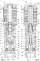
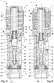
- the punch holder 2 includes a guiding body 4 provided with a mounting cavity 5, in particular a through cavity and extending along a longitudinal axis X, adapted to slidably receive the punching tool 3 and a driving assembly 6 connected to the guiding body 4 and provided with a beating element 7 having a first operating end 8 arranged to interact with a ram of the punching machine and a first connecting end 9 coupled to a second connecting end 32 of the punching tool 3 by means of a threaded coupling.
- the latter allows a relative rotation between the beating element 7 and the punching tool 3 for linear movement of the latter with respect to the beating element 7 along an adjustment stroke C, between an initial adjustment position A and a final adjustment position B.
- the engagement portion 20 of the threaded coupling that joins the two connecting ends 8, 32 of the beating element 7 and the punching tool has a maximum length L1
- the engagement portion 20 has a minimum length L2.
- the minimum length L2 is such as to guarantee a number of engagement threads in the engagement portion 20 of the threaded coupling suitable to the force transmitted by the beating element 7 to the punching tool 3, i.e. such as to prevent them from being excessively stressed in operation and being damaged.
- Anti-rotation means 63, 64 are provided to prevent rotation of the punching tool 3 with respect to the guiding body 4 when the beating element 7 is rotated about the longitudinal axis X.
- the anti-rotation means comprise, for example, a transverse pin 63 fixed to the punching tool 3, almost orthogonal to the longitudinal axis X, and slidably engaging by means of a protruding portion thereof with a longitudinal slot 64 made on a side wall of the guiding body 4.
- the punching tool 3 comprises a second operating end 36 opposite the second connecting end 32, adapted to interact (in particular cut, drill, punch) with a cutting end 36a with a piece 100 and having a defined sharpening length Ls which is longer than the adjustment stroke C of the punching tool 3 with respect to the beating element 7, between the initial adjustment position A and the final adjustment position B.
- the beating element 7, 17 is driven by the ram of a press assembly of the punching machine so as to move the punching tool 3 linearly along the longitudinal axis X with respect to the guiding body 4 along a working stroke W between a non-operating internal position N and an operating external position T.
- the non-operating internal position N of the punching tool 3 the second operating end 36 of the punching tool 3 is contained inside the punch holder 2, in particular inside the guiding body 4, while in the operating external position T the second operating end 36 partially protrudes from the punch holder 2 and inserts with the cutting end 36a thereof into the underlying punching die 60 so as to punch the piece 100.
- the punch holder 2 is provided with an extractor element 27, of known type, fixed to a first end part 4a of the guiding body 4 from which the punching tool 3 protrudes, adapted to abut and press the piece 100 against the punching die 60 and provided with a respective opening for the exit of the second operating end 36 of the punching tool 3 when moved by the beating element 7 in the operating external position T.
- the driving assembly 6 of a known type, comprises a base element 16 fixed to a second end part 4b of the guiding body 4 which is opposite the first end part 4a and is arranged to slidingly guide the beating element 7 along a longitudinal axis X.
- the driving assembly 6 further includes elastic means 28 interposed between the base element 16 and the first operating end 8 of the beating element 7 to return the latter to a raised position (corresponding to the non-operating internal position N of the punching tool 3) so as to extract the punching tool 3 from the piece 100 after the working.
- the punching apparatus 1 further comprises a stopping element 10 having a first end 11 fixed inside a connecting cavity 15 made at one of the connecting ends 9, 42 of the beating element 7 or the punching tool 3 and arranged to receive the remaining connecting end 32 of the punching tool 3 or the beating element 7 and a second end 12 inserted into a stopping cavity 34 made at the remaining connecting end 32 and slidable inside said stopping cavity 34 during the linear movement between the initial adjustment position A and the final adjustment position B.
- the second end 12 of the stopping element 10 is provided with first stopping means 22 adapted to abut second stopping means 35 provided at an opening of the stopping cavity 34 so as to prevent the stopping element 10 from disengaging from the stopping cavity and stopping the adjustment stroke C of the punching tool 3 in the final adjustment position B.
- the connecting cavity 15 is made in the first connecting end 9 of the beating element 7 and comprises an outer portion 15a that is threaded and adapted to receive and engage with the second connecting end 32, externally threaded, of the punching tool 3.
- the connecting cavity 15 of the first connecting end 9 of the beating element 7 further comprises an inner portion 15b adapted to receive, and fixed to, the first end 11 of the stopping element 10, while the second end 12 thereof is slidably housed in the stopping cavity 34 made in the second connecting end 32 of the punching tool 3.
- the stopping element 10 is sized and fixed with its first end 11 inside the connecting cavity 15, so that the punch element 3 also in the final adjustment position B with respect to the beating element 7 and in the operating external position T with respect to the guiding body 4 does not collide with the second operating end 36 against said extractor element 27, as better explained in the following description.
- the stopping element 10 has, for example, a cylindrical shape and the first stopping means 22 comprise an annular protrusion made on an edge of the second end 12 and adapted to be abut by the second stopping means 35 provided in the stopping cavity 34 and comprising an elastic ring, in particular a split ring, housed in a respective inner annular groove made at the opening of the stopping cavity 34.
- fixing means 14 comprising, for example, a respective elastic ring mounted on a first annular seat made on an outer wall of the first end 11 and engaging in an assembly configuration with a second annular seat made on an inner wall of the inner portion 15b of the connecting cavity 15.
- the punching tool 3 comprises a punch tip holder or adapter 31 provided with the second connecting end 32 and a punch tip 35 or cutting tip that is reversibly fixed to the punch tip holder 31, opposite the second connecting end 32 and provided with the second operating end 36 with the cutting end 36a adapted to interact with the piece 100.
- the punch tip holder 31 comprises a third connecting end 37 opposite the second connecting end 32 provided with a connecting seat 38 adapted to receive a connecting portion 39 of the punch tip 33 opposite the second operating end 36.
- the connecting seat 38 and the connecting portion 39 have, for example, a complementary truncated-conical shape and are coaxial to the longitudinal axis X of the punch holder 2.
- the punch tip holder 31 and the punch tip 33 are fixed to one another by means of a screw 61.
- the stopping cavity 34 that is made in the second connecting end 32 of the punch tip holder 2 is a through cavity in order to allow the end 61 of the screw to be screwed into a threaded hole made on an upper wall of the connecting portion 39 of the punch tip 33.
- the stopping cavity 34 comprises a shoulder intended to abut the head of the screw 61.
- the punch tip holder 31 is configured to be mounted on the respective beating element 7, the first connecting end 9 and the second connecting end 32 being complementary, and is capable of receiving in the connecting seat 38 one of a set or plurality of punch tips 33, each of which is adapted to perform a respective working on the piece 100.
- the punching tool 3 (more precisely the punch tip 33 in the example of the figures) is new and sharp
- the latter is screwed to the beating element 7 so as to be arranged in the initial adjustment position A.
- the engagement portion 20 of the threaded coupling, which joins the two connecting ends 8, 32 of the beating element 7 and of the punching tool 3 has a maximum length L1, i.e. the second connecting end 32 of the punching tool 3 is completely inserted in the first connecting end 9 of the beating element 7 since the second operating end 36 of the punching tool 3 has a length equal to the maximum sharpening length Ls.
- the distance between the first stopping means 22 of the stopping element 10 and the second stopping means 25 provided in the stopping cavity 34 is also maximum ( figures 2 to 4 ).
- the punching tool 3 having a maximum sharpening length Ls, in the working stroke W, between the non-operating internal position N and the operating external position T, the punching tool is able to correctly perform the cutting or punching of the piece 100.
- the punching tool 3 (punch tip 33) during its operating life is subjected to periodic sharpening operations following which the length of its second operating end 36 progressively decreases.
- the position of the punching tool 3 along the longitudinal axis X with respect to the beating element 7 must be adjusted by appropriately rotating the beating element about the longitudinal axis X.
- the stopping element 10 prevents the punching tool 3 from being screwed insufficiently to the beating element 7, i.e. it prevents the length of the engagement portion 20 of the threaded coupling from being less than the minimum length L2 in an incorrect mounting condition.
- this minimum length below this minimum length (with a tolerance range of about 1 mm) the second operating end 36 collides with the extractor element 27 causing damage to the latter and to the whole punch holder 6 since the working stroke W is longer than the remaining length of the second operating end 36.
- the punching apparatus 1 of the invention it is therefore possible to control the position of the punching element 3 with respect to the beating element 7 and to prevent operators from making incorrect adjustments, in particular in the case of excessive sharpening of the punching element 3, which could damage the extractor element and/or the punch holder 1 in operation. Hence the adjustment can be performed safely without risk of accidental errors even by inexperienced operators.
- the stopping element 10 further allows to have a minimum length L2 of the engagement portion 20 of the threaded coupling between the beating element 7 and the punching tool 3 capable of guaranteeing a number of engaged threads of this engagement portion 20 that is appropriate for the force which is transmitted by the beating element 7 to the punching tool 3, and prevents the engaged threads from being excessively stressed in operation and being damaged.
- the punching apparatus 1 which is provided with a locking element 10 positioned inside the connecting ends 9, 32 of the beating element 7 and the punching tool 3, is of simple, robust, and reliable construction.
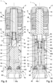
- FIG 8 a variant of the punching apparatus 1 of the invention is illustrated which differs from the embodiment described above and illustrated in figures 1 to 7 , for the punching tool 23 that comprises a single-body punch or cutting tool provided with a second connecting end 52 connected to the first connecting end 9 of the beating element 7 and a second operating end 56 opposite the second connecting end 52 and adapted to interact by means of the cutting end 56a with the piece 100.
- the second operating end 56 is substantially the same as that of the punch tip 33.
- the second connecting end 52 comprises the stopping cavity 54 inside which the second end 12 of the stopping element 10 is slidably inserted, which is slidable inside said stopping cavity 54 during the movement of the punch 23 between the initial adjustment position A and the final adjustment position B.
- second stopping means 35 are provided, which are adapted to abut the first stopping means 22 of the stopping element 10 in the final adjustment position B.
- Figure 9 illustrates in section another variant of the punching apparatus 1 of the invention which differs from the embodiment described above and illustrated in figures 1 to 7 in that the connecting cavity 45 is made in the second connecting end 42 of the punching tool 13 and comprises an outer portion 45a, threaded and adapted to receive and engage the first connecting end 19, externally threaded, of the beating element 17, and an inner portion 45b adapted to receive and fixed to the first end 11 of the stopping element 10.
- the second end 12 of the stopping element is slidably housed in the stopping cavity 24 made in the first connecting end 19 of the beating element 17.
- second stopping means 45 are provided, adapted to abut the first stopping means 22 of the stopping element 10 in the final adjustment position B.
- the beating element 17 also comprises the first operating end 18 adapted to interact with the ram of the punching machine.
- the punching tool 13 comprises a punch tip holder 41 or adapter provided with the second connecting end 42 and a punch tip 43 or cutting tip that is reversibly fixed to the punch tip holder 41 on the opposite side to the second connecting end 42 and provided with the second operating end 46 or cutting end adapted to interact with the piece 100 with the cutting end 36a.
- the punch tip holder 41 and the punch tip 43 of this variant are substantially identical to the embodiment of figures 1 to 7 .
Landscapes
- Engineering & Computer Science (AREA)
- Mechanical Engineering (AREA)
- Punching Or Piercing (AREA)
- Perforating, Stamping-Out Or Severing By Means Other Than Cutting (AREA)
Applications Claiming Priority (2)
| Application Number | Priority Date | Filing Date | Title |
|---|---|---|---|
| IT102019000019421A IT201900019421A1 (it) | 2019-10-21 | 2019-10-21 | Apparato di punzonatura |
| PCT/IB2020/059803 WO2021079252A1 (en) | 2019-10-21 | 2020-10-19 | Punching apparatus |
Publications (2)
| Publication Number | Publication Date |
|---|---|
| EP4048457A1 EP4048457A1 (en) | 2022-08-31 |
| EP4048457B1 true EP4048457B1 (en) | 2023-12-13 |
Family
ID=69701448
Family Applications (1)
| Application Number | Title | Priority Date | Filing Date |
|---|---|---|---|
| EP20821366.0A Active EP4048457B1 (en) | 2019-10-21 | 2020-10-19 | Punching apparatus |
Country Status (11)
| Country | Link |
|---|---|
| US (1) | US12090543B2 (da) |
| EP (1) | EP4048457B1 (da) |
| JP (1) | JP7471404B2 (da) |
| KR (1) | KR102763861B1 (da) |
| CN (1) | CN114585458B (da) |
| DK (1) | DK4048457T3 (da) |
| ES (1) | ES2972566T3 (da) |
| FI (1) | FI4048457T3 (da) |
| IT (1) | IT201900019421A1 (da) |
| PL (1) | PL4048457T3 (da) |
| WO (1) | WO2021079252A1 (da) |
Family Cites Families (23)
| Publication number | Priority date | Publication date | Assignee | Title |
|---|---|---|---|---|
| ZA715348B (en) * | 1970-08-20 | 1972-04-26 | B & R Prod Proprietary Ltd | Multi-purpose sheet metal folding press,punch,and nibbling machine |
| GB1322123A (en) * | 1971-03-26 | 1973-07-04 | Strandell P O | Punching apparatus |
| US3937113A (en) * | 1974-03-05 | 1976-02-10 | Unipunch Products, Inc. | Punching apparatus |
| GB2031780B (en) * | 1978-10-11 | 1982-11-10 | Mercer Nairne & Co Ltd | Shear-proof punch and punching tool including such a punch |
| CA1155758A (en) * | 1979-12-26 | 1983-10-25 | Kenneth J. Wilson | Adjustable punch head |
| FR2572963B1 (fr) * | 1984-11-09 | 1986-12-12 | Esswein Sa | Outil de presse a parties travaillantes demontables sous presse |
| US5131303A (en) * | 1991-08-12 | 1992-07-21 | Wilson Tool International | Punch assembly |
| US5329835A (en) * | 1992-10-07 | 1994-07-19 | Wilson Tool International, Inc. | Adjustable length punch set assembly |
| DE19505754C1 (de) * | 1995-02-20 | 1996-05-02 | Mate Punch And Die Gmbh | Stanzstempeleinheit |
| US6311597B1 (en) * | 1999-05-24 | 2001-11-06 | Humdinger, Inc. | Self-guiding punch and die set |
| JP4499221B2 (ja) * | 1999-10-05 | 2010-07-07 | 株式会社アマダ | 金型装置 |
| US6276247B1 (en) * | 2000-03-03 | 2001-08-21 | Strippit, Inc. | Adjustable punch assembly with releasable locking |
| US7698979B2 (en) | 2004-09-22 | 2010-04-20 | Amada Tool America, Inc. | Biasing assembly for a punching device |
| ITPD20070377A1 (it) | 2007-11-13 | 2009-05-14 | Special Springs Srl | Dispositivo punzonatore con premilamiera |
| US8413561B2 (en) * | 2009-11-10 | 2013-04-09 | Mate Precision Tooling, Inc. | Multiple punch and die assembly |
| ES2630113T3 (es) | 2013-05-27 | 2017-08-18 | Salvagnini Italia S.P.A. | Aparato de punzonado |
| BR112017001660B1 (pt) | 2014-07-29 | 2021-05-11 | Salvagnini Italia S.P.A. | aparelho de perfuração, e, ferramenta de máquina de perfuração |
| CN105618810B (zh) | 2016-03-29 | 2017-07-25 | 宁波韵升股份有限公司 | 一种用于棒料产品的自动打孔机 |
| KR20170010872A (ko) * | 2017-01-18 | 2017-02-01 | 이윤주 | 펀칭장치 |
| JP6888475B2 (ja) | 2017-08-16 | 2021-06-16 | トヨタ紡織株式会社 | パンチプレス装置 |
| CN108941370B (zh) | 2018-08-14 | 2020-04-07 | 中国航发南方工业有限公司 | 用于冲压设备的防压块坠落保险装置及冲压设备 |
| KR101968619B1 (ko) * | 2018-08-14 | 2019-04-12 | 여동훈 | 코일 포장용 아우터 에지 프로텍트 링 제작 시스템 |
| KR102180542B1 (ko) * | 2019-11-13 | 2020-11-19 | 킨더스 주식회사 | 펀칭기 |
-
2019
- 2019-10-21 IT IT102019000019421A patent/IT201900019421A1/it unknown
-
2020
- 2020-10-19 EP EP20821366.0A patent/EP4048457B1/en active Active
- 2020-10-19 US US17/770,748 patent/US12090543B2/en active Active
- 2020-10-19 KR KR1020227013067A patent/KR102763861B1/ko active Active
- 2020-10-19 WO PCT/IB2020/059803 patent/WO2021079252A1/en not_active Ceased
- 2020-10-19 JP JP2022523662A patent/JP7471404B2/ja active Active
- 2020-10-19 CN CN202080073580.0A patent/CN114585458B/zh active Active
- 2020-10-19 ES ES20821366T patent/ES2972566T3/es active Active
- 2020-10-19 PL PL20821366.0T patent/PL4048457T3/pl unknown
- 2020-10-19 DK DK20821366.0T patent/DK4048457T3/da active
- 2020-10-19 FI FIEP20821366.0T patent/FI4048457T3/fi active
Also Published As
| Publication number | Publication date |
|---|---|
| EP4048457A1 (en) | 2022-08-31 |
| CN114585458A (zh) | 2022-06-03 |
| PL4048457T3 (pl) | 2024-05-06 |
| US12090543B2 (en) | 2024-09-17 |
| IT201900019421A1 (it) | 2021-04-21 |
| WO2021079252A1 (en) | 2021-04-29 |
| KR20220065842A (ko) | 2022-05-20 |
| FI4048457T3 (fi) | 2024-03-18 |
| JP2022553062A (ja) | 2022-12-21 |
| KR102763861B1 (ko) | 2025-02-07 |
| ES2972566T3 (es) | 2024-06-13 |
| DK4048457T3 (da) | 2024-03-04 |
| JP7471404B2 (ja) | 2024-04-19 |
| US20220362830A1 (en) | 2022-11-17 |
| CN114585458B (zh) | 2023-12-08 |
Similar Documents
| Publication | Publication Date | Title |
|---|---|---|
| US8904911B2 (en) | Sleeve for a punch assembly | |
| EP2289657A1 (en) | Deburring Tool | |
| JP2018505061A (ja) | 着脱可能なパンチ先端体を備えるパンチアセンブリ | |
| JPH03196905A (ja) | 穿孔装置 | |
| US10421137B2 (en) | Multiple tool | |
| CN212527730U (zh) | 一种弹性坐标定位打点器 | |
| EP4048457B1 (en) | Punching apparatus | |
| RU2791543C1 (ru) | Пробивное устройство | |
| CN210254305U (zh) | 镗刀 | |
| KR20190100752A (ko) | 절삭형 공구장치 | |
| AT513629B1 (de) | Werkzeugmaschine mit einer Primärspule zur kontaktlosen Energie- und/oder Signalübertragung | |
| KR101872641B1 (ko) | 홈 가공구 | |
| KR102004590B1 (ko) | 보조 절단칼이 구비된 파이프 절단기 | |
| EP1574307B1 (en) | Planing tool | |
| CN110576199B (zh) | 端面切槽刀体 | |
| KR20200036878A (ko) | 절삭 공구 및 조절 장치가 장착된 절삭 공구를 위한 조절 장치 | |
| AU2018101473B4 (en) | Improvements relating to cutting devices to make internal keyways, splines and other shapes in blind bores and through bores | |
| CN214769406U (zh) | 一种可调倒角深度的孔口倒角工具 | |
| KR102316849B1 (ko) | 유압 천공기용 펀치 | |
| DE102006043959B4 (de) | Bearbeitungsmaschine und Verfahren | |
| KR20180051247A (ko) | 공작기계장치 | |
| JP4770254B2 (ja) | 切削工具 | |
| JP4304831B2 (ja) | 切削工具 | |
| EP2351627A1 (en) | Clamping device for cutting inserts | |
| JP2001353605A (ja) | 切削工具 |
Legal Events
| Date | Code | Title | Description |
|---|---|---|---|
| STAA | Information on the status of an ep patent application or granted ep patent |
Free format text: STATUS: UNKNOWN |
|
| STAA | Information on the status of an ep patent application or granted ep patent |
Free format text: STATUS: THE INTERNATIONAL PUBLICATION HAS BEEN MADE |
|
| PUAI | Public reference made under article 153(3) epc to a published international application that has entered the european phase |
Free format text: ORIGINAL CODE: 0009012 |
|
| STAA | Information on the status of an ep patent application or granted ep patent |
Free format text: STATUS: REQUEST FOR EXAMINATION WAS MADE |
|
| 17P | Request for examination filed |
Effective date: 20220419 |
|
| AK | Designated contracting states |
Kind code of ref document: A1 Designated state(s): AL AT BE BG CH CY CZ DE DK EE ES FI FR GB GR HR HU IE IS IT LI LT LU LV MC MK MT NL NO PL PT RO RS SE SI SK SM TR |
|
| DAV | Request for validation of the european patent (deleted) | ||
| DAX | Request for extension of the european patent (deleted) | ||
| P01 | Opt-out of the competence of the unified patent court (upc) registered |
Effective date: 20230515 |
|
| GRAP | Despatch of communication of intention to grant a patent |
Free format text: ORIGINAL CODE: EPIDOSNIGR1 |
|
| STAA | Information on the status of an ep patent application or granted ep patent |
Free format text: STATUS: GRANT OF PATENT IS INTENDED |
|
| INTG | Intention to grant announced |
Effective date: 20230721 |
|
| GRAS | Grant fee paid |
Free format text: ORIGINAL CODE: EPIDOSNIGR3 |
|
| GRAA | (expected) grant |
Free format text: ORIGINAL CODE: 0009210 |
|
| STAA | Information on the status of an ep patent application or granted ep patent |
Free format text: STATUS: THE PATENT HAS BEEN GRANTED |
|
| AK | Designated contracting states |
Kind code of ref document: B1 Designated state(s): AL AT BE BG CH CY CZ DE DK EE ES FI FR GB GR HR HU IE IS IT LI LT LU LV MC MK MT NL NO PL PT RO RS SE SI SK SM TR |
|
| REG | Reference to a national code |
Ref country code: GB Ref legal event code: FG4D |
|
| REG | Reference to a national code |
Ref country code: CH Ref legal event code: EP |
|
| REG | Reference to a national code |
Ref country code: DE Ref legal event code: R096 Ref document number: 602020022834 Country of ref document: DE |
|
| REG | Reference to a national code |
Ref country code: IE Ref legal event code: FG4D |
|
| REG | Reference to a national code |
Ref country code: DK Ref legal event code: T3 Effective date: 20240229 |
|
| REG | Reference to a national code |
Ref country code: FI Ref legal event code: FGE |
|
| REG | Reference to a national code |
Ref country code: SE Ref legal event code: TRGR |
|
| PG25 | Lapsed in a contracting state [announced via postgrant information from national office to epo] |
Ref country code: GR Free format text: LAPSE BECAUSE OF FAILURE TO SUBMIT A TRANSLATION OF THE DESCRIPTION OR TO PAY THE FEE WITHIN THE PRESCRIBED TIME-LIMIT Effective date: 20240314 |
|
| REG | Reference to a national code |
Ref country code: LT Ref legal event code: MG9D |
|
| PG25 | Lapsed in a contracting state [announced via postgrant information from national office to epo] |
Ref country code: LT Free format text: LAPSE BECAUSE OF FAILURE TO SUBMIT A TRANSLATION OF THE DESCRIPTION OR TO PAY THE FEE WITHIN THE PRESCRIBED TIME-LIMIT Effective date: 20231213 |
|
| REG | Reference to a national code |
Ref country code: NL Ref legal event code: MP Effective date: 20231213 |
|
| PG25 | Lapsed in a contracting state [announced via postgrant information from national office to epo] |
Ref country code: LT Free format text: LAPSE BECAUSE OF FAILURE TO SUBMIT A TRANSLATION OF THE DESCRIPTION OR TO PAY THE FEE WITHIN THE PRESCRIBED TIME-LIMIT Effective date: 20231213 Ref country code: GR Free format text: LAPSE BECAUSE OF FAILURE TO SUBMIT A TRANSLATION OF THE DESCRIPTION OR TO PAY THE FEE WITHIN THE PRESCRIBED TIME-LIMIT Effective date: 20240314 Ref country code: BG Free format text: LAPSE BECAUSE OF FAILURE TO SUBMIT A TRANSLATION OF THE DESCRIPTION OR TO PAY THE FEE WITHIN THE PRESCRIBED TIME-LIMIT Effective date: 20240313 |
|
| PG25 | Lapsed in a contracting state [announced via postgrant information from national office to epo] |
Ref country code: NL Free format text: LAPSE BECAUSE OF FAILURE TO SUBMIT A TRANSLATION OF THE DESCRIPTION OR TO PAY THE FEE WITHIN THE PRESCRIBED TIME-LIMIT Effective date: 20231213 |
|
| PG25 | Lapsed in a contracting state [announced via postgrant information from national office to epo] |
Ref country code: RS Free format text: LAPSE BECAUSE OF FAILURE TO SUBMIT A TRANSLATION OF THE DESCRIPTION OR TO PAY THE FEE WITHIN THE PRESCRIBED TIME-LIMIT Effective date: 20231213 Ref country code: NO Free format text: LAPSE BECAUSE OF FAILURE TO SUBMIT A TRANSLATION OF THE DESCRIPTION OR TO PAY THE FEE WITHIN THE PRESCRIBED TIME-LIMIT Effective date: 20240313 Ref country code: NL Free format text: LAPSE BECAUSE OF FAILURE TO SUBMIT A TRANSLATION OF THE DESCRIPTION OR TO PAY THE FEE WITHIN THE PRESCRIBED TIME-LIMIT Effective date: 20231213 Ref country code: LV Free format text: LAPSE BECAUSE OF FAILURE TO SUBMIT A TRANSLATION OF THE DESCRIPTION OR TO PAY THE FEE WITHIN THE PRESCRIBED TIME-LIMIT Effective date: 20231213 Ref country code: HR Free format text: LAPSE BECAUSE OF FAILURE TO SUBMIT A TRANSLATION OF THE DESCRIPTION OR TO PAY THE FEE WITHIN THE PRESCRIBED TIME-LIMIT Effective date: 20231213 |
|
| REG | Reference to a national code |
Ref country code: ES Ref legal event code: FG2A Ref document number: 2972566 Country of ref document: ES Kind code of ref document: T3 Effective date: 20240613 |
|
| PG25 | Lapsed in a contracting state [announced via postgrant information from national office to epo] |
Ref country code: IS Free format text: LAPSE BECAUSE OF FAILURE TO SUBMIT A TRANSLATION OF THE DESCRIPTION OR TO PAY THE FEE WITHIN THE PRESCRIBED TIME-LIMIT Effective date: 20240413 |
|
| PG25 | Lapsed in a contracting state [announced via postgrant information from national office to epo] |
Ref country code: CZ Free format text: LAPSE BECAUSE OF FAILURE TO SUBMIT A TRANSLATION OF THE DESCRIPTION OR TO PAY THE FEE WITHIN THE PRESCRIBED TIME-LIMIT Effective date: 20231213 |
|
| PG25 | Lapsed in a contracting state [announced via postgrant information from national office to epo] |
Ref country code: SK Free format text: LAPSE BECAUSE OF FAILURE TO SUBMIT A TRANSLATION OF THE DESCRIPTION OR TO PAY THE FEE WITHIN THE PRESCRIBED TIME-LIMIT Effective date: 20231213 |
|
| PG25 | Lapsed in a contracting state [announced via postgrant information from national office to epo] |
Ref country code: SM Free format text: LAPSE BECAUSE OF FAILURE TO SUBMIT A TRANSLATION OF THE DESCRIPTION OR TO PAY THE FEE WITHIN THE PRESCRIBED TIME-LIMIT Effective date: 20231213 Ref country code: SK Free format text: LAPSE BECAUSE OF FAILURE TO SUBMIT A TRANSLATION OF THE DESCRIPTION OR TO PAY THE FEE WITHIN THE PRESCRIBED TIME-LIMIT Effective date: 20231213 Ref country code: RO Free format text: LAPSE BECAUSE OF FAILURE TO SUBMIT A TRANSLATION OF THE DESCRIPTION OR TO PAY THE FEE WITHIN THE PRESCRIBED TIME-LIMIT Effective date: 20231213 Ref country code: IS Free format text: LAPSE BECAUSE OF FAILURE TO SUBMIT A TRANSLATION OF THE DESCRIPTION OR TO PAY THE FEE WITHIN THE PRESCRIBED TIME-LIMIT Effective date: 20240413 Ref country code: EE Free format text: LAPSE BECAUSE OF FAILURE TO SUBMIT A TRANSLATION OF THE DESCRIPTION OR TO PAY THE FEE WITHIN THE PRESCRIBED TIME-LIMIT Effective date: 20231213 Ref country code: CZ Free format text: LAPSE BECAUSE OF FAILURE TO SUBMIT A TRANSLATION OF THE DESCRIPTION OR TO PAY THE FEE WITHIN THE PRESCRIBED TIME-LIMIT Effective date: 20231213 |
|
| PG25 | Lapsed in a contracting state [announced via postgrant information from national office to epo] |
Ref country code: PT Free format text: LAPSE BECAUSE OF FAILURE TO SUBMIT A TRANSLATION OF THE DESCRIPTION OR TO PAY THE FEE WITHIN THE PRESCRIBED TIME-LIMIT Effective date: 20240415 |
|
| PG25 | Lapsed in a contracting state [announced via postgrant information from national office to epo] |
Ref country code: PT Free format text: LAPSE BECAUSE OF FAILURE TO SUBMIT A TRANSLATION OF THE DESCRIPTION OR TO PAY THE FEE WITHIN THE PRESCRIBED TIME-LIMIT Effective date: 20240415 |
|
| REG | Reference to a national code |
Ref country code: DE Ref legal event code: R097 Ref document number: 602020022834 Country of ref document: DE |
|
| PLBE | No opposition filed within time limit |
Free format text: ORIGINAL CODE: 0009261 |
|
| STAA | Information on the status of an ep patent application or granted ep patent |
Free format text: STATUS: NO OPPOSITION FILED WITHIN TIME LIMIT |
|
| PG25 | Lapsed in a contracting state [announced via postgrant information from national office to epo] |
Ref country code: SI Free format text: LAPSE BECAUSE OF FAILURE TO SUBMIT A TRANSLATION OF THE DESCRIPTION OR TO PAY THE FEE WITHIN THE PRESCRIBED TIME-LIMIT Effective date: 20231213 |
|
| PG25 | Lapsed in a contracting state [announced via postgrant information from national office to epo] |
Ref country code: SI Free format text: LAPSE BECAUSE OF FAILURE TO SUBMIT A TRANSLATION OF THE DESCRIPTION OR TO PAY THE FEE WITHIN THE PRESCRIBED TIME-LIMIT Effective date: 20231213 |
|
| REG | Reference to a national code |
Ref country code: AT Ref legal event code: UEP Ref document number: 1640055 Country of ref document: AT Kind code of ref document: T Effective date: 20231213 |
|
| 26N | No opposition filed |
Effective date: 20240916 |
|
| PG25 | Lapsed in a contracting state [announced via postgrant information from national office to epo] |
Ref country code: MC Free format text: LAPSE BECAUSE OF FAILURE TO SUBMIT A TRANSLATION OF THE DESCRIPTION OR TO PAY THE FEE WITHIN THE PRESCRIBED TIME-LIMIT Effective date: 20231213 |
|
| PG25 | Lapsed in a contracting state [announced via postgrant information from national office to epo] |
Ref country code: BE Free format text: LAPSE BECAUSE OF NON-PAYMENT OF DUE FEES Effective date: 20241031 Ref country code: LU Free format text: LAPSE BECAUSE OF NON-PAYMENT OF DUE FEES Effective date: 20241019 |
|
| REG | Reference to a national code |
Ref country code: BE Ref legal event code: MM Effective date: 20241031 |
|
| PG25 | Lapsed in a contracting state [announced via postgrant information from national office to epo] |
Ref country code: IE Free format text: LAPSE BECAUSE OF NON-PAYMENT OF DUE FEES Effective date: 20241019 |
|
| REG | Reference to a national code |
Ref country code: CH Ref legal event code: U11 Free format text: ST27 STATUS EVENT CODE: U-0-0-U10-U11 (AS PROVIDED BY THE NATIONAL OFFICE) Effective date: 20251101 |
|
| PGFP | Annual fee paid to national office [announced via postgrant information from national office to epo] |
Ref country code: DE Payment date: 20251029 Year of fee payment: 6 |
|
| PGFP | Annual fee paid to national office [announced via postgrant information from national office to epo] |
Ref country code: GB Payment date: 20251027 Year of fee payment: 6 |
|
| PGFP | Annual fee paid to national office [announced via postgrant information from national office to epo] |
Ref country code: AT Payment date: 20251029 Year of fee payment: 6 |
|
| PGFP | Annual fee paid to national office [announced via postgrant information from national office to epo] |
Ref country code: FI Payment date: 20251027 Year of fee payment: 6 Ref country code: DK Payment date: 20251027 Year of fee payment: 6 Ref country code: IT Payment date: 20251021 Year of fee payment: 6 |
|
| PGFP | Annual fee paid to national office [announced via postgrant information from national office to epo] |
Ref country code: FR Payment date: 20251027 Year of fee payment: 6 |
|
| PGFP | Annual fee paid to national office [announced via postgrant information from national office to epo] |
Ref country code: TR Payment date: 20251007 Year of fee payment: 6 |
|
| PGFP | Annual fee paid to national office [announced via postgrant information from national office to epo] |
Ref country code: CH Payment date: 20251101 Year of fee payment: 6 Ref country code: SE Payment date: 20251027 Year of fee payment: 6 |
|
| PGFP | Annual fee paid to national office [announced via postgrant information from national office to epo] |
Ref country code: PL Payment date: 20251006 Year of fee payment: 6 |
|
| PG25 | Lapsed in a contracting state [announced via postgrant information from national office to epo] |
Ref country code: CY Free format text: LAPSE BECAUSE OF FAILURE TO SUBMIT A TRANSLATION OF THE DESCRIPTION OR TO PAY THE FEE WITHIN THE PRESCRIBED TIME-LIMIT; INVALID AB INITIO Effective date: 20201019 |
|
| PGFP | Annual fee paid to national office [announced via postgrant information from national office to epo] |
Ref country code: ES Payment date: 20251103 Year of fee payment: 6 |
|
| PG25 | Lapsed in a contracting state [announced via postgrant information from national office to epo] |
Ref country code: HU Free format text: LAPSE BECAUSE OF FAILURE TO SUBMIT A TRANSLATION OF THE DESCRIPTION OR TO PAY THE FEE WITHIN THE PRESCRIBED TIME-LIMIT; INVALID AB INITIO Effective date: 20201019 |