EP4049907B1 - Bloc collecteur pour système de freinage de véhicule et véhicule - Google Patents
Bloc collecteur pour système de freinage de véhicule et véhicule Download PDFInfo
- Publication number
- EP4049907B1 EP4049907B1 EP20881903.7A EP20881903A EP4049907B1 EP 4049907 B1 EP4049907 B1 EP 4049907B1 EP 20881903 A EP20881903 A EP 20881903A EP 4049907 B1 EP4049907 B1 EP 4049907B1
- Authority
- EP
- European Patent Office
- Prior art keywords
- valve mounting
- mounting hole
- hole
- solenoid valve
- manifold block
- Prior art date
- Legal status (The legal status is an assumption and is not a legal conclusion. Google has not performed a legal analysis and makes no representation as to the accuracy of the status listed.)
- Active
Links
Images
Classifications
-
- B—PERFORMING OPERATIONS; TRANSPORTING
- B60—VEHICLES IN GENERAL
- B60T—VEHICLE BRAKE CONTROL SYSTEMS OR PARTS THEREOF; BRAKE CONTROL SYSTEMS OR PARTS THEREOF, IN GENERAL; ARRANGEMENT OF BRAKING ELEMENTS ON VEHICLES IN GENERAL; PORTABLE DEVICES FOR PREVENTING UNWANTED MOVEMENT OF VEHICLES; VEHICLE MODIFICATIONS TO FACILITATE COOLING OF BRAKES
- B60T17/00—Component parts, details, or accessories of power brake systems not covered by groups B60T8/00, B60T13/00 or B60T15/00, or presenting other characteristic features
- B60T17/04—Arrangements of piping, valves in the piping, e.g. cut-off valves, couplings or air hoses
-
- B—PERFORMING OPERATIONS; TRANSPORTING
- B60—VEHICLES IN GENERAL
- B60T—VEHICLE BRAKE CONTROL SYSTEMS OR PARTS THEREOF; BRAKE CONTROL SYSTEMS OR PARTS THEREOF, IN GENERAL; ARRANGEMENT OF BRAKING ELEMENTS ON VEHICLES IN GENERAL; PORTABLE DEVICES FOR PREVENTING UNWANTED MOVEMENT OF VEHICLES; VEHICLE MODIFICATIONS TO FACILITATE COOLING OF BRAKES
- B60T13/00—Transmitting braking action from initiating means to ultimate brake actuator with power assistance or drive; Brake systems incorporating such transmitting means, e.g. air-pressure brake systems
- B60T13/10—Transmitting braking action from initiating means to ultimate brake actuator with power assistance or drive; Brake systems incorporating such transmitting means, e.g. air-pressure brake systems with fluid assistance, drive, or release
- B60T13/66—Electrical control in fluid-pressure brake systems
- B60T13/68—Electrical control in fluid-pressure brake systems by electrically-controlled valves
- B60T13/686—Electrical control in fluid-pressure brake systems by electrically-controlled valves in hydraulic systems or parts thereof
-
- B—PERFORMING OPERATIONS; TRANSPORTING
- B60—VEHICLES IN GENERAL
- B60T—VEHICLE BRAKE CONTROL SYSTEMS OR PARTS THEREOF; BRAKE CONTROL SYSTEMS OR PARTS THEREOF, IN GENERAL; ARRANGEMENT OF BRAKING ELEMENTS ON VEHICLES IN GENERAL; PORTABLE DEVICES FOR PREVENTING UNWANTED MOVEMENT OF VEHICLES; VEHICLE MODIFICATIONS TO FACILITATE COOLING OF BRAKES
- B60T8/00—Arrangements for adjusting wheel-braking force to meet varying vehicular or ground-surface conditions, e.g. limiting or varying distribution of braking force
- B60T8/32—Arrangements for adjusting wheel-braking force to meet varying vehicular or ground-surface conditions, e.g. limiting or varying distribution of braking force responsive to a speed condition, e.g. acceleration or deceleration
- B60T8/34—Arrangements for adjusting wheel-braking force to meet varying vehicular or ground-surface conditions, e.g. limiting or varying distribution of braking force responsive to a speed condition, e.g. acceleration or deceleration having a fluid pressure regulator responsive to a speed condition
- B60T8/36—Arrangements for adjusting wheel-braking force to meet varying vehicular or ground-surface conditions, e.g. limiting or varying distribution of braking force responsive to a speed condition, e.g. acceleration or deceleration having a fluid pressure regulator responsive to a speed condition including a pilot valve responding to an electromagnetic force
- B60T8/3615—Electromagnetic valves specially adapted for anti-lock brake and traction control systems
- B60T8/3675—Electromagnetic valves specially adapted for anti-lock brake and traction control systems integrated in modulator units
-
- B—PERFORMING OPERATIONS; TRANSPORTING
- B60—VEHICLES IN GENERAL
- B60T—VEHICLE BRAKE CONTROL SYSTEMS OR PARTS THEREOF; BRAKE CONTROL SYSTEMS OR PARTS THEREOF, IN GENERAL; ARRANGEMENT OF BRAKING ELEMENTS ON VEHICLES IN GENERAL; PORTABLE DEVICES FOR PREVENTING UNWANTED MOVEMENT OF VEHICLES; VEHICLE MODIFICATIONS TO FACILITATE COOLING OF BRAKES
- B60T8/00—Arrangements for adjusting wheel-braking force to meet varying vehicular or ground-surface conditions, e.g. limiting or varying distribution of braking force
- B60T8/32—Arrangements for adjusting wheel-braking force to meet varying vehicular or ground-surface conditions, e.g. limiting or varying distribution of braking force responsive to a speed condition, e.g. acceleration or deceleration
- B60T8/34—Arrangements for adjusting wheel-braking force to meet varying vehicular or ground-surface conditions, e.g. limiting or varying distribution of braking force responsive to a speed condition, e.g. acceleration or deceleration having a fluid pressure regulator responsive to a speed condition
- B60T8/36—Arrangements for adjusting wheel-braking force to meet varying vehicular or ground-surface conditions, e.g. limiting or varying distribution of braking force responsive to a speed condition, e.g. acceleration or deceleration having a fluid pressure regulator responsive to a speed condition including a pilot valve responding to an electromagnetic force
- B60T8/3615—Electromagnetic valves specially adapted for anti-lock brake and traction control systems
- B60T8/3675—Electromagnetic valves specially adapted for anti-lock brake and traction control systems integrated in modulator units
- B60T8/368—Electromagnetic valves specially adapted for anti-lock brake and traction control systems integrated in modulator units combined with other mechanical components, e.g. pump units, master cylinders
-
- B—PERFORMING OPERATIONS; TRANSPORTING
- B60—VEHICLES IN GENERAL
- B60T—VEHICLE BRAKE CONTROL SYSTEMS OR PARTS THEREOF; BRAKE CONTROL SYSTEMS OR PARTS THEREOF, IN GENERAL; ARRANGEMENT OF BRAKING ELEMENTS ON VEHICLES IN GENERAL; PORTABLE DEVICES FOR PREVENTING UNWANTED MOVEMENT OF VEHICLES; VEHICLE MODIFICATIONS TO FACILITATE COOLING OF BRAKES
- B60T13/00—Transmitting braking action from initiating means to ultimate brake actuator with power assistance or drive; Brake systems incorporating such transmitting means, e.g. air-pressure brake systems
- B60T13/10—Transmitting braking action from initiating means to ultimate brake actuator with power assistance or drive; Brake systems incorporating such transmitting means, e.g. air-pressure brake systems with fluid assistance, drive, or release
- B60T13/12—Transmitting braking action from initiating means to ultimate brake actuator with power assistance or drive; Brake systems incorporating such transmitting means, e.g. air-pressure brake systems with fluid assistance, drive, or release the fluid being liquid
- B60T13/16—Transmitting braking action from initiating means to ultimate brake actuator with power assistance or drive; Brake systems incorporating such transmitting means, e.g. air-pressure brake systems with fluid assistance, drive, or release the fluid being liquid using pumps directly, i.e. without interposition of accumulators or reservoirs
Definitions
- the present application relates to the technical field of vehicle braking systems, and more particularly to a manifold block for a vehicle braking system and a vehicle including the manifold block for a vehicle braking system.
- the vehicle braking system is an important part of the vehicle for ensuring safety performance, and the vehicle braking system includes the manifold block and other hydraulic structural elements installed on it (such as hydraulic pumps, solenoid valves, pedal simulator, etc.).
- the manifold block can be connected to the master brake cylinder via the brake line, and to one or more wheel brakes via the brake line.
- the design of the manifold block in the vehicle braking system is not optimized, with the result that after the manifold block is connected with other hydraulic structural components, master brake cylinders, wheel brakes, etc. and assembled, the appearance of the hydraulic unit in the whole vehicle braking system is irregular, so that the hydraulic brake system that needs to be installed into the engine room of the vehicle occupies a larger space, which is easy to collide with other components during assembly and disassembly.
- installation of vehicle braking system that takes up more space in the engine room will lead to the problem of insufficient installation space, and the installation process will be very inconvenient.
- US 2007/0018498 A1 concerns a brake control apparatus including a hydraulic brake unit.
- US 2002/0149259 A1 discloses a hydraulic braking pressure control unit.
- US 2018/0326962 A1 discloses a valve block for an electronic brake system.
- the present application aims to solve one of the technical problems in the related art at least to a certain extent.
- the technical problem to be solved by this application is: the design of the manifold block is not optimized, which leads to the problems of insufficient installation space and inconvenient installation process when installing the vehicle braking system into the engine room.
- a manifold block of the vehicle braking system as well as vehicle is provided.
- a manifold block for a vehicle braking system includes a hydraulic unit body, a solenoid valve mounting hole for mounting a solenoid valve, a sensor mounting hole for mounting a liquid pressure sensor, and a simulator accommodation part for installing a pedal simulator.
- a solenoid valve mounting face is provided on the hydraulic unit body. The solenoid valve mounting hole, the sensor mounting hole and the simulator accommodation part are all arranged on the solenoid valve mounting face.
- the hydraulic unit body is further provided with a connecting surface and a longitudinal surface.
- the connecting surface and the solenoid valve mounting face are oppositely arranged.
- the longitudinal surface is between the connecting surface and the solenoid valve mounting face.
- the hydraulic unit body is further provided with a piston pump mounting hole for mounting a piston pump.
- the piston pump mounting hole penetrates the hydraulic unit body from the solenoid valve mounting face and extends to the connecting surface.
- the connecting surface is provided with port for connecting wheel brake cylinder.
- the longitudinal surface is provided with a master brake cylinder hole for installing the master brake cylinder.
- the hydraulic unit body is further provided with a lateral surface that is between the connecting surface and the solenoid valve mounting face.
- the lateral surface is vertical to the longitudinal surface.
- the lateral surface is provided with a leakage chamber.
- the hydraulic unit body is also provided with a leakage hole that connects the leakage chamber and the piston pump mounting hole.
- the leakage chamber is coaxial with the leakage hole, and the center axis of the leakage chamber is perpendicular to the center axis of the piston pump mounting hole and the center axis of the master brake cylinder hole.
- the connecting surface is provided with a plurality of ports which are arranged circumferentially around the piston pump mounting hole.
- the center axis of the piston pump mounting hole is parallel to the center axis of the solenoid valve mounting hole, the center axis of the sensor mounting hole and the center axis of the simulator accommodating part, and is perpendicular to the center axis of the master cylinder hole.
- the hydraulic unit body is further provided with oil passages inside it.
- the oil passages comprise a first oil hole and a second oil hole which is vertically connected with the first oil hole.
- the end of the first oil hole which is apart from the second oil hole is connected to the solenoid valve mounting hole.
- the first oil hole is provided coaxially with the solenoid valve mounting hole.
- the oil passages further include a third oil hole and a fourth oil hole which is vertically connected with the third oil hole.
- the end of the third oil hole which is far away from the fourth oil hole is connected to the sensor mounting hole.
- the third oil hole is coaxially arranged with the sensor mounting hole.
- the solenoid valve mounting holes includes a brake booster valve mounting hole, a brake pressure reduction valve mounting hole, a diagnostic valve mounting hole, a first regulating valve mounting hole, a second regulating valve mounting hole, and a third regulating valve mounting hole.
- a brake booster valve is mounted on the solenoid valve mounting face by the brake booster valve mounting hole, and a brake pressure reduction valve is mounted on the solenoid valve mounting face by the brake pressure reduction valve mounting hole.
- a diagnostic valve is mounted on the solenoid valve mounting face by the diagnostic valve mounting hole.
- a master brake cylinder outlet pressure regulating valve is mounted on the solenoid valve mounting face by the first regulating valve mounting hole.
- a piston pump outlet pressure regulating valve is mounted on the solenoid valve mounting face by the second regulating valve mounting hole.
- a pedal simulator pressure regulating valve is mounted on the solenoid valve mounting face by the third regulating valve mounting hole.
- the solenoid valve mounting hole is stepped circular blind hole.
- the simulator accommodation part, the solenoid valve mounting hole, and the pressure sensor mounting holes are all provided on the solenoid valve mounting face of the manifold block, that is, the structural members in the manifold block related to electric control, such as solenoid valves, liquid pressure sensors, pedal simulator, are distributed on the same solenoid valve mounting face of the manifold block.
- the structural members can be combined or separated with electronic control hardware at one time when the manifold block is installed to the engine room, so that the manifold block is not easy to collide with other parts during the assembling or separating processes and the assembling process of the manifold block is relatively better.
- the structure of the manifold block is more compact, which reduces the space occupied by the hydraulic brake system installed in the vehicle engine room, thus allows a smaller space as well as makes it more convenience when the vehicle braking system is installed to the engine room.
- the embodiment of the invention also provides a vehicle comprising the manifold block for a vehicle braking system.
- the vehicle further includes an electronic control unit that covers and connects to the solenoid valve mounting face of the manifold block.
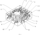
- one of the embodiments of the invention provides a manifold block for vehicle braking system.
- the manifold block includes a hydraulic unit body 1, a solenoid valve mounting hole 2 used for mounting solenoid valve (includes various kinds of valves required by the hydraulic system, such as booster valve, pressure reduction valve, pressure regulating valve, etc.), a pressure sensor mounting hole 3 used for mounting liquid pressure sensor and a simulator accommodation part 4 used for mounting pedal simulator.
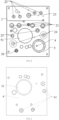
- the solenoid valve mounting face 5 is provided on the hydraulic unit body 1 ( FIG.2 is a schematic structural diagram of the solenoid valve mounting face of the manifold block of the vehicle braking system provided by an embodiment of the application.
- the solenoid valve mounting face 5 shown in FIG.2 is also the upward arranged surface in FIG. 1 ).
- the solenoid valve mounting hole 2, the pressure sensor mounting hole 3 and the simulator accommodation part 4 are all provided on the solenoid valve mounting face 5.
- the liquid pressure sensor is used to detect the pressure of the brake fluid during the braking process through the vehicle braking system and feed it back to the ECU (Electronic Control Unit), so that the pressure value of the brake fluid of the manifold block is monitored in real time, thus the safety performance of the manifold block is improved.
- the solenoid valve mounting hole 2, the sensor mounting hole 3, and the simulator accommodation part 4 can all be manufactured on the solenoid valve mounting face 5 of the manifold block by drilling, reaming and other processing technologies.
- the simulator accommodation part 4, the solenoid valve mounting hole 2, and the pressure sensor mounting holes 3 are all provided on the solenoid valve mounting face 5 of the manifold block, that is, the structural members in the manifold block related to electric control, such as solenoid valves, liquid pressure sensors, pedal simulator, are distributed on the same solenoid valve mounting face 5 of the manifold block.
- the structural members can be combined or separated with electronic control hardware at one time when the manifold block is installed to the engine room, so that the manifold block is not easy to collide with other parts during the assembling or separating process, and the assembling process of the manifold block is relatively better.
- the structure of the manifold block is more compact, which reduces the space occupied by the hydraulic brake system installed in the vehicle engine room, thus allows a smaller space as well as makes it more convenience when the vehicle braking system is installed to the engine room.
- the hydraulic unit body 1 is further provided with a connecting surface 6 ( FIG. 3 is a schematic structural diagram of the connecting surface of the manifold block of the vehicle braking system provided by an embodiment of the invention.
- the connecting surface 6 shown in FIG. 3 is also the downward arranged surface in FIG. 1 ) and a longitudinal surface 7 (in FIG. 1 , the longitudinal surface 7 is the surface facing left of the manifold block).
- the connecting surface 6 and the solenoid valve mounting face 5 are oppositely arranged.
- the longitudinal surface 7 is between the connecting surface 6 and the solenoid valve mounting face 5.
- the hydraulic unit body 1 is further provided with a piston pump mounting hole 51 for mounting a piston pump.
- the piston pump mounting hole 51 penetrates the hydraulic unit body 1 from the solenoid valve mounting face 5 and extends to the connecting surface 6.
- the connecting surface 6 is provided with ports 61 for connecting the wheel brake cylinder.
- the longitudinal surface 7 is provided with a master brake cylinder hole 71 for installing the master brake cylinder.
- the hydraulic unit body 1 is further provided with a lateral surface 8 (the lateral surface 8 is the surface which is adjacent to the longitudinal surface 7 and is facing left) that is between the connecting surface 6 and the solenoid valve mounting face 5.
- the lateral surface 8 is vertical to the longitudinal surface 7, and is provided with a leakage chamber 81.
- the hydraulic unit body 1 is also provided with a leakage hole 82 that connects the leakage chamber 81 and the piston pump mounting hole 51.
- the leakage chamber 81 is used to store the brake fluid leaked from the piston pump and prevent the brake fluid leaked from the piston pump from flowing to other parts of the manifold block. At the same time, the leakage chamber 81 also extends the service life of the piston pump because of isolating the piston pump from external dust and impurities.
- the leakage chamber 81 is coaxial with the leakage hole 82, and the center axis of the leakage chamber 81 is perpendicular to the center axis of the piston pump mounting hole 51 and the center axis of the master brake cylinder hole 71.
- the leakage hole 82 is provided at the bottom of the leakage chamber 81 and coaxially with the leakage chamber 81, so as to facilitate the manufacturing of the leakage hole 82 and reduce the manufacturing cost of the manifold block.
- the connecting surface 6 is provided with a plurality of ports 61 which are arranged circumferentially around the piston pump mounting hole 51, wherein the ports 61 transmit the kinetic energy (reciprocating linear motion) of the master brake cylinder to the brake wheels (clamping or releasing the wheels) so as to achieve the braking function of the vehicle.
- the number of the ports 61 is provided according to the number of the brake wheels of the vehicle.
- the vehicle has four wheels, and the connection surface 6 is provided with four ports 61 circumferentially surrounding the piston pump mounting hole 51.
- the ports 61 are internally provided with internally thread that can be connected to the externally threaded brake fluid pipes in order to connect and seal between the brake fluid pipes and the manifold block.
- the center axis of the piston pump mounting hole 51 is parallel to the center axis of the solenoid valve mounting hole 2, the center axis of the sensor mounting holes 3 and the center axis of the simulator accommodating part 4, and is perpendicular to the center axis of the master cylinder hole 71.
- the amount of the sloping holes of the manifold block is reduced, making it possible for an easier processing and lower cost for manufacturing the manifold block.
- oil passages 11 are further provided in the hydraulic unit body 1.
- the oil passages comprise a first oil hole 111 and a second oil hole 112 which is vertically connected with the first oil hole 111.
- the first oil hole 111 is vertically provided in the hydraulic unit body 1 and connected to the solenoid valve mounting hole 2, while the second oil hole 112 is horizontally provided in the hydraulic unit body 1 and connected to the first oil hole 111.
- the end of the first oil hole 111 which is apart from the second oil hole 112, is connected to the solenoid valve mounting hole 2.
- the first oil hole 111 is provided coaxially with the solenoid valve mounting hole 2.
- the oil passages 11 are arranged inside the hydraulic unit body 1 according to the demand of the vehicle brake system, so as to make a connection between the solenoid valve mounting hole 2, the master cylinder hole 71, the piston pump mounting hole 51, the ports 61, the simulator accommodation part 4 and so on, thus a highly integrated vehicle brake system is finally achieved by the manifold block.
- the mounting holes, ports 61, accommodation part are all provided vertically or horizontally inside the manifold block, the oil passages 11 are as well provided vertically or horizontally in the hydraulic unit body 1 (although in some embodiments, a small amount of sloping holes may be arranged inside the hydraulic unit body 1 as required). As a result, the amount of the sloping holes of the manifold block is reduced, making it possible for an easier processing of making the oil passages 11 and lower cost for manufacturing the manifold block.
- the solenoid valve mounting hole 2 includes a brake booster valve mounting hole 21, a brake pressure reduction valve mounting hole 22, a diagnostic valve mounting hole 23, a first regulating valve mounting hole 24, a second regulating valve mounting hole 25, and a third regulating valve mounting hole 26.
- a brake booster valve (not shown) is mounted on the solenoid valve mounting face 5 by the brake booster valve mounting hole 21, and a brake pressure reduction valve (not shown) is mounted on the solenoid valve mounting face 5 by the brake pressure reduction valve mounting hole 22.
- a diagnostic valve (not shown) is mounted on the solenoid valve mounting face 5 by the diagnostic valve mounting hole 23.
- a master brake cylinder outlet pressure regulating valve (not shown) is mounted on the solenoid valve mounting face 5 by the first regulating valve mounting hole 24.
- a piston pump outlet pressure regulating valve (not shown) is mounted on the solenoid valve mounting face 5 by the second regulating valve mounting hole 25.
- a pedal simulator pressure regulating valve (not shown) is mounted on the solenoid valve mounting face 5 by the third regulating valve mounting hole 26.
- solenoid valves are designed according to the functions to be realized by the manifold block, including but not limited to a brake booster valve mounting hole 21, a brake pressure reduction valve mounting hole 22, a diagnostic valve mounting hole 23, a first regulating valve mounting hole 24, a second regulating valve mounting hole 25, a third regulating valve mounting hole 26 and so on.
- Each of the solenoid valves corresponds to a solenoid valve mounting hole.
- first oil holes 111 connecting the above mentioned different kinds of solenoid valve mounting hole 2 are distributed in the hydraulic unit body 1, and the different first oil holes 111 are vertically arranged in the hydraulic unit body 1, meanwhile the second oil holes 112 which are vertically connected with the first oil holes 111 are horizontally and layeredly arranged in the hydraulic unit body 1, thereby simplifying the manufacturing of the oil passages 11 and greatly reducing the manufacturing cost of the manifold block.
- the diagnostic valve can tell whether the manifold block works under a normal condition or not by detecting the brake fluid pressure of the manifold block, thereby improving the safety of the manifold block and extending the service life of the manifold block.
- the piston pump, the piston pump outlet pressure regulating valve, the hydraulic cylinder, the hydraulic cylinder outlet pressure regulating valve, and the related oil passages 11 together form a complete hydraulic system.
- the hydraulic pump is the power element
- the hydraulic cylinder is the functional element converting the hydraulic power into linear reciprocating motion, so that the wheel brake members (brake disc, brake drum, etc.) connected (directly or indirectly) to the hydraulic cylinder can make an action of clamping or releasing to achieve the braking function of the vehicle.
- the simulator pressure regulating valve sends the brake fluid into the pedal simulator through its matching oil passage 11. Since the pedal simulator has a structure of elastic elements (spring, disc spring, rubber, etc.), a reverse force can be transmitted to the pedal during the braking process of the vehicle, and the driver of the vehicle will feel the reverse force through the pedal, that is, the pedal feeling.
- the simulator pressure regulating valve can give a suitable reaction force to the foot pedal by adjusting the pressure entering the pedal simulator, which adds the comfort of the vehicle driver.
- the brake booster valve and the brake pressure reduction valve belong to the ABS (antilock brake system) of the vehicle braking system, which can realize the anti-lock braking function of the vehicle and ensure that the vehicle has the steering capability during emergency braking, thus the safety of the vehicle is enhanced.
- the oil passages 11 further includes a third oil hole (not shown) and a fourth oil hole (not shown) which is vertically connected with the third oil hole.
- the end of the third oil hole, which is far away from the fourth oil hole, is connected to the sensor mounting hole 3.
- the third oil hole is coaxially arranged with the sensor mounting hole 3. It can be understood that the third oil hole is vertically distributed inside the hydraulic unit body 1 as the same way the first oil hole is, and the fourth oil hole is horizontally (and layered) arranged inside the hydraulic unit body 1 as the same way the second oil hole 112 is. It will further reduce the number of sloping oil holes in the hydraulic unit body 1, thereby simplifying the machining process of the oil passages 11 inside the manifold block and further reducing the manufacturing cost of manifold block.
- the solenoid valve mounting hole 2 is a stepped circular blind hole. It can be understood that the solenoid valve mounting holes 2 should be designed according to the shape of the solenoid valves, and should not be limited to a stepped circular blind hole. The solenoid valves are fixed by the stepped circular blind holes in the manifold block, making the entire manifold block more stable and reliable.
- the manifold block is a square block made of a light metal material, such as aluminum alloy or other kinds of light alloy materials. It can be easily understood that most of the square blocks are cuboids, which serve as the skeleton of the entire vehicle braking system and are installed in the left side of the engine room together with the vehicle braking system.
- the square block shaped manifold block is easy to manufacture and assemble in the engine room.
- a vehicle is further provided in one of the embodiments of the invention, which includes the above mentioned manifold block of the vehicle braking system.
- the vehicle further includes an electronic control unit (not shown) that covers and connects to the solenoid valve mounting face 5 of the manifold block.
- an electronic control unit (not shown) that covers and connects to the solenoid valve mounting face 5 of the manifold block.
- the simulator mounting hole, the solenoid valve mounting hole 2 and the sensor mounting hole 3 are all provided on the solenoid valve mounting face of the manifold block, and the electronic control unit covers and connects to the surface. Therefore, the pedal simulator, the solenoid valves and hydraulic sensors can be directly connected with the corresponding electronic control units in the engine room, thereby improving the signal transmission rate and lower the usage of communication cables, reducing the space for cables in the engine room, and improving the space utilization of the engine room.
- first and second are only used for descriptive purposes, and cannot be understood or indicate or imply relative importance, or implicitly indicate the number of indicated technical features. Therefore, the features defined with “first” and “second” may explicitly or implicitly include one or more of these features. In the description of the invention, “multiple” means two or more, unless it is specifically defined otherwise.
- the terms “installed”, “connected”, “connected”, “fixed” and other terms should be understood in a broad sense, for example, it can be a fixed connection or a detachable connection, or integrated, or it can be a mechanical connection or an electrical connection, or it can be directly connected or indirectly connected through an intermediate medium, and it can be the internal communication of two components or the interaction relationship between two components.
- installed can be a fixed connection or a detachable connection, or integrated, or it can be a mechanical connection or an electrical connection, or it can be directly connected or indirectly connected through an intermediate medium, and it can be the internal communication of two components or the interaction relationship between two components.
- the first feature "on” or “under” the second feature may be in direct contact, or be indirectly contact through an intermediary.
- the "above” of the first feature on the second feature may mean that the first feature is directly above or indirectly above the second feature, or it simply means that the level of the first feature is higher than the second feature.
- the “below” of the first feature under the second feature may be that the first feature is directly below or indirectly below the second feature, or it simply means that the level of the first feature is lower than the second feature.
Landscapes
- Engineering & Computer Science (AREA)
- Transportation (AREA)
- Mechanical Engineering (AREA)
- Physics & Mathematics (AREA)
- Electromagnetism (AREA)
- Fluid Mechanics (AREA)
- Regulating Braking Force (AREA)
Claims (10)
- Un bloc collecteur pour le système de freinage d'un véhicule, comprenant un corps d'unité hydraulique (1), un trou de montage d'électrovanne (2) pour le montage d'une électrovanne, un trou de montage de capteur (3) pour le montage d'un capteur de pression de liquide, et une pièce de logement de simulateur (4) pour l'installation d'un simulateur de pédale ; dans lequel le corps de l'unité hydraulique (1) est pourvu d'une face de montage de l'électrovanne (5) ; caractérisé en ce que le trou de montage de l'électrovanne (2), le trou de montage du capteur (3) et la pièce de logement du simulateur (4) sont tous disposés sur la face de montage de l'électrovanne (5).
- Le bloc collecteur pour un système de freinage de véhicule selon la revendication 1, dans lequel le corps de l'unité hydraulique (1) est en outre pourvu d'une surface de connexion (6) et d'une surface longitudinale (7) ; dans lequel la surface de connexion (6) et la face de montage de l'électrovanne (5) sont disposées de manière opposée ; dans lequel la surface longitudinale (7) se trouve entre la surface de connexion (6) et la face de montage de l'électrovanne (5) ; dans lequel le corps de l'unité hydraulique (1) est en outre pourvu d'un trou de montage de la pompe à piston (51) pour le montage d'une pompe à piston ; dans lequel le trou de montage de la pompe à piston (51) pénètre dans le corps de l'unité hydraulique (1) à partir de la face de montage de l'électrovanne (5) et s'étend jusqu'à la surface de connexion (6) ; dans lequel la surface de connexion (6) est pourvue d'orifices (61) pour le raccordement du cylindre de frein de roue ; dans lequel la surface longitudinale (7) est pourvue d'un trou de maître-cylindre de frein (71) pour l'installation du maître-cylindre de frein.
- Le bloc collecteur pour un système de freinage de véhicule selon la revendication 2, dans lequel le corps de l'unité hydraulique (1) est en outre pourvu d'une surface latérale (8) qui se trouve entre la surface de connexion (6) et la face de montage de l'électrovanne (5) ; dans lequel la surface latérale (8) est verticale par rapport à la surface longitudinale (7), et est pourvue d'une chambre de fuite (81) ; dans lequel le corps de l'unité hydraulique (1) est également pourvu d'un trou de fuite (82) qui relie la chambre de fuite (81) et le trou de montage de la pompe à pistons (51).
- Le bloc collecteur pour un système de freinage de véhicule selon la revendication 3, dans lequel la chambre de fuite (81) est coaxiale avec le trou de fuite (82), et l'axe central de la chambre de fuite (82) est perpendiculaire à l'axe central du trou de montage de la pompe à piston (51) et à l'axe central du trou du maître-cylindre de frein (71).
- Le bloc collecteur pour système de freinage de véhicule selon l'une des revendications 2 à 4, dans lequel l'axe central du trou de montage de la pompe à piston (51) est parallèle à l'axe central du trou de montage de l'électrovanne (2), à l'axe central du trou de montage du capteur (3) et à l'axe central de la pièce de logement du simulateur (4), et est perpendiculaire à l'axe central du trou du maître-cylindre (71).
- Le bloc collecteur pour un système de freinage de véhicule selon la revendication 5, dans lequel le corps de l'unité hydraulique (1) est en outre pourvu de passages d'huile (11) à l'intérieur ; dans lequel les passages d'huile (11) comprennent un premier trou d'huile (111) et un second trou d'huile (112) qui est relié verticalement au premier trou d'huile (111) ; dans lequel l'extrémité du premier trou d'huile (111) qui est séparée du second trou d'huile (112) est reliée au trou de montage de l'électrovanne (2) ; dans lequel le premier trou d'huile (111) est coaxial avec le trou de montage de l'électrovanne (2).
- Le bloc collecteur pour système de freinage de véhicule selon la revendication 6, dans lequel les passages d'huile (11) comprennent en outre un troisième trou d'huile et un quatrième trou d'huile qui est relié verticalement au troisième trou d'huile ; dans lequel l'extrémité du troisième trou d'huile qui est éloignée du quatrième trou d'huile est reliée au trou de montage du capteur (3) ; dans lequel le troisième trou d'huile est disposé de manière coaxiale avec le trou de montage du capteur (3).
- Le bloc collecteur pour un système de freinage de véhicule selon l'une des revendications 5 à 7, dans lequel le trou de montage de l'électrovanne (2) comprend un trou de montage de la soupape de servofrein (21), un trou de montage de la soupape de réduction de la pression de freinage (22), un trou de montage de la soupape de diagnostic (23), un premier trou de montage de la soupape de régulation (24), un deuxième trou de montage de la soupape de régulation (25), et un troisième trou de montage de la soupape de régulation (26) ;
dans lequel une soupape de servofrein est montée sur la face de montage de l'électrovanne (5) par le trou de montage de la soupape de servofrein (21), et une soupape de réduction de la pression de freinage est montée sur la face de montage de l'électrovanne (5) par le trou de montage de la soupape de réduction de la pression de freinage (22) ; dans lequel une soupape de diagnostic est montée sur la face de montage de l'électrovanne (5) par le trou de montage de la soupape de diagnostic (23), et une soupape de régulation de la pression de sortie du maître-cylindre de frein est montée sur la face de montage de l'électrovanne (5) par le premier trou de montage de la soupape de régulation (24) ; une soupape de régulation de la pression de sortie de la pompe à piston est montée sur la face de montage de l'électrovanne (5) par le deuxième trou de montage de la soupape de régulation (25), et une soupape de régulation de la pression du simulateur de pédale est montée sur la face de montage de l'électrovanne (5) par le troisième trou de montage de la soupape de régulation (26). - Véhicule comprenant le bloc collecteur pour un système de freinage de véhicule selon l'une des revendications 1 à 8.
- Véhicule selon la revendication 9, dans lequel le véhicule comprend en outre une unité de commande électronique qui recouvre et se connecte à la face de montage de l'électrovanne (5) du bloc collecteur.
Applications Claiming Priority (2)
| Application Number | Priority Date | Filing Date | Title |
|---|---|---|---|
| CN201911044456.7A CN112744206B (zh) | 2019-10-30 | 2019-10-30 | 车辆制动系统的油路块及车辆 |
| PCT/CN2020/122466 WO2021083002A1 (fr) | 2019-10-30 | 2020-10-21 | Bloc collecteur pour système de freinage de véhicule et véhicule |
Publications (3)
| Publication Number | Publication Date |
|---|---|
| EP4049907A1 EP4049907A1 (fr) | 2022-08-31 |
| EP4049907A4 EP4049907A4 (fr) | 2022-12-21 |
| EP4049907B1 true EP4049907B1 (fr) | 2024-08-14 |
Family
ID=75641681
Family Applications (1)
| Application Number | Title | Priority Date | Filing Date |
|---|---|---|---|
| EP20881903.7A Active EP4049907B1 (fr) | 2019-10-30 | 2020-10-21 | Bloc collecteur pour système de freinage de véhicule et véhicule |
Country Status (6)
| Country | Link |
|---|---|
| US (2) | US12291176B2 (fr) |
| EP (1) | EP4049907B1 (fr) |
| JP (1) | JP7443511B2 (fr) |
| CN (1) | CN112744206B (fr) |
| ES (1) | ES2991530T3 (fr) |
| WO (1) | WO2021083002A1 (fr) |
Families Citing this family (1)
| Publication number | Priority date | Publication date | Assignee | Title |
|---|---|---|---|---|
| CN115946669A (zh) * | 2022-12-31 | 2023-04-11 | 安徽鑫铂铝业股份有限公司 | 一种用于汽车abs电磁阀阀块的抗压铝合金型材 |
Family Cites Families (18)
| Publication number | Priority date | Publication date | Assignee | Title |
|---|---|---|---|---|
| JPH10258724A (ja) | 1997-03-21 | 1998-09-29 | Toyota Motor Corp | 液圧ブレーキ装置 |
| US7204566B2 (en) | 2001-04-17 | 2007-04-17 | Toyota Jidosha Kabushiki Kaisha | Hydraulic braking pressure control unit |
| DE10245068A1 (de) * | 2002-09-27 | 2004-04-08 | Continental Teves Ag & Co. Ohg | Hydraulikaggregat für schlupfgeregelte Bremsanlagen |
| JP4283756B2 (ja) | 2004-10-29 | 2009-06-24 | 日信工業株式会社 | 車両用ブレーキ液圧制御装置 |
| JP4841884B2 (ja) | 2005-07-19 | 2011-12-21 | 日立オートモティブシステムズ株式会社 | ブレーキユニット |
| JP4923839B2 (ja) * | 2006-08-11 | 2012-04-25 | 株式会社アドヴィックス | 車両用ブレーキ液圧制御ユニット |
| JP2008044457A (ja) * | 2006-08-11 | 2008-02-28 | Advics:Kk | 車両用ブレーキ液圧制御ユニット |
| DE102007047208A1 (de) | 2007-10-02 | 2009-04-09 | Lucas Automotive Gmbh | Elektro-hydraulisches Bremsaggregat für ein Landfahrzeug |
| JP5015315B2 (ja) * | 2010-12-24 | 2012-08-29 | 日立オートモティブシステムズ株式会社 | ブレーキ液圧制御装置 |
| CN202716864U (zh) * | 2012-08-02 | 2013-02-06 | 浙江亚太机电股份有限公司 | 一种集成式汽车制动系统液压单元 |
| DE102012223059B4 (de) * | 2012-12-13 | 2025-03-20 | Robert Bosch Gmbh | Hydraulikblock für ein Hydroaggregat einer schlupfgeregelten, hydraulischen Fahrzeugbremsanlage |
| CN203402178U (zh) * | 2013-07-23 | 2014-01-22 | 浙江万向精工有限公司 | 一种辅助制动装置 |
| DE102014208871A1 (de) * | 2014-05-12 | 2015-11-12 | Robert Bosch Gmbh | Hydraulikblock für ein Hydraulikaggregat einer Schlupfregelung einer hydraulischen Fahrzeugbremsanlage |
| CN104608753A (zh) * | 2015-02-02 | 2015-05-13 | 杭州金兰达新能源科技有限公司 | 一种纯电动汽车新型wbs汽车制动器 |
| KR102006497B1 (ko) | 2017-05-11 | 2019-10-08 | 주식회사 만도 | 전자식 브레이크 시스템용 밸브블록 |
| CN107891852A (zh) * | 2017-12-18 | 2018-04-10 | 浙江力邦合信智能制动系统股份有限公司 | 一种踏板模拟装置 |
| CN107891850A (zh) * | 2017-12-18 | 2018-04-10 | 浙江力邦合信智能制动系统股份有限公司 | 一种带有解耦功能的集成式电液制动系统 |
| DE102018220573A1 (de) * | 2018-11-29 | 2020-06-04 | Robert Bosch Gmbh | Hydraulikblock für eine hydraulische Fremdkraft-Fahrzeuganlage |
-
2019
- 2019-10-30 CN CN201911044456.7A patent/CN112744206B/zh active Active
-
2020
- 2020-10-21 EP EP20881903.7A patent/EP4049907B1/fr active Active
- 2020-10-21 US US17/773,537 patent/US12291176B2/en active Active
- 2020-10-21 WO PCT/CN2020/122466 patent/WO2021083002A1/fr not_active Ceased
- 2020-10-21 ES ES20881903T patent/ES2991530T3/es active Active
- 2020-10-21 JP JP2022525651A patent/JP7443511B2/ja active Active
-
2025
- 2025-04-07 US US19/171,525 patent/US20250229760A1/en active Pending
Also Published As
| Publication number | Publication date |
|---|---|
| EP4049907A4 (fr) | 2022-12-21 |
| CN112744206A (zh) | 2021-05-04 |
| EP4049907A1 (fr) | 2022-08-31 |
| US12291176B2 (en) | 2025-05-06 |
| US20220379867A1 (en) | 2022-12-01 |
| JP7443511B2 (ja) | 2024-03-05 |
| WO2021083002A1 (fr) | 2021-05-06 |
| ES2991530T3 (es) | 2024-12-03 |
| CN112744206B (zh) | 2022-03-18 |
| US20250229760A1 (en) | 2025-07-17 |
| JP2023500320A (ja) | 2023-01-05 |
Similar Documents
| Publication | Publication Date | Title |
|---|---|---|
| KR102841690B1 (ko) | 전자식 브레이크 시스템 | |
| CN114007912B (zh) | 制动系统的控制装置结构 | |
| EP2641798B1 (fr) | Structure de fixation à une carrosserie de véhicule pour un actionneur de frein électrique | |
| CN108263366B (zh) | 车辆的制动系统 | |
| US20230356700A1 (en) | Integrated Brake Apparatus of Vehicle and Vehicle | |
| US8915338B2 (en) | Input device of vehicle brake system | |
| US20250229760A1 (en) | Manifold block for vehicle braking system and vehicle | |
| US9290170B2 (en) | Vehicle-body attachment structure for electric brake actuator | |
| EP2835297B1 (fr) | Ensemble tige-poussoir de piston, maître-cylindre et procédé de fabrication pour l'ensemble tige-poussoir de piston | |
| KR20150125989A (ko) | 압력 제공 디바이스 및 브레이크 시스템 | |
| KR20240001191A (ko) | 유압 파워 브레이크 시스템의 상용 브레이크 유닛용 유압 블록 | |
| KR20190087550A (ko) | 브레이크 제어부의 유압 유닛용 유압 블록 및 그 제조 방법 | |
| EP2463167B1 (fr) | Modulateur hydraulique | |
| CN103303289B (zh) | 一种汽车集成线控制动系统 | |
| US9566968B2 (en) | Input device of vehicle brake system | |
| CN115257678B (zh) | 一种液压电子制动手刹 | |
| JP5698106B2 (ja) | 電動ブレーキアクチュエータ | |
| JP5364077B2 (ja) | 車両用ブレーキシステムの入力装置 | |
| JP7457148B2 (ja) | 油圧式自動車ブレーキシステムのための小型ブレーキ装置 | |
| CA2339343A1 (fr) | Systeme de frein a disque intelligent | |
| CN210258383U (zh) | 一种具有多种工作模式的双卡钳混合双回路制动系统 | |
| KR20240147595A (ko) | 전자식 브레이크 시스템의 전면 장착형 리저버 조립체 | |
| JP2026503780A (ja) | ブレーキ力装置のためのユニットシステムおよびユニットシステムからブレーキ力装置を製造するための方法 | |
| CN121590500A (zh) | 汽车电子液压制动系统液压控制单元阀块 | |
| EP1740428B1 (fr) | Dispositif d'équilibrage de pression de freinage et système de freinage comprenant un tel dispositif. |
Legal Events
| Date | Code | Title | Description |
|---|---|---|---|
| STAA | Information on the status of an ep patent application or granted ep patent |
Free format text: STATUS: THE INTERNATIONAL PUBLICATION HAS BEEN MADE |
|
| PUAI | Public reference made under article 153(3) epc to a published international application that has entered the european phase |
Free format text: ORIGINAL CODE: 0009012 |
|
| STAA | Information on the status of an ep patent application or granted ep patent |
Free format text: STATUS: REQUEST FOR EXAMINATION WAS MADE |
|
| 17P | Request for examination filed |
Effective date: 20220524 |
|
| AK | Designated contracting states |
Kind code of ref document: A1 Designated state(s): AL AT BE BG CH CY CZ DE DK EE ES FI FR GB GR HR HU IE IS IT LI LT LU LV MC MK MT NL NO PL PT RO RS SE SI SK SM TR |
|
| A4 | Supplementary search report drawn up and despatched |
Effective date: 20221123 |
|
| RIC1 | Information provided on ipc code assigned before grant |
Ipc: B60T 13/12 20060101AFI20221117BHEP |
|
| DAV | Request for validation of the european patent (deleted) | ||
| DAX | Request for extension of the european patent (deleted) | ||
| GRAP | Despatch of communication of intention to grant a patent |
Free format text: ORIGINAL CODE: EPIDOSNIGR1 |
|
| STAA | Information on the status of an ep patent application or granted ep patent |
Free format text: STATUS: GRANT OF PATENT IS INTENDED |
|
| INTG | Intention to grant announced |
Effective date: 20240430 |
|
| GRAS | Grant fee paid |
Free format text: ORIGINAL CODE: EPIDOSNIGR3 |
|
| GRAA | (expected) grant |
Free format text: ORIGINAL CODE: 0009210 |
|
| STAA | Information on the status of an ep patent application or granted ep patent |
Free format text: STATUS: THE PATENT HAS BEEN GRANTED |
|
| AK | Designated contracting states |
Kind code of ref document: B1 Designated state(s): AL AT BE BG CH CY CZ DE DK EE ES FI FR GB GR HR HU IE IS IT LI LT LU LV MC MK MT NL NO PL PT RO RS SE SI SK SM TR |
|
| REG | Reference to a national code |
Ref country code: GB Ref legal event code: FG4D |
|
| REG | Reference to a national code |
Ref country code: CH Ref legal event code: EP |
|
| REG | Reference to a national code |
Ref country code: DE Ref legal event code: R096 Ref document number: 602020035960 Country of ref document: DE |
|
| REG | Reference to a national code |
Ref country code: IE Ref legal event code: FG4D |
|
| REG | Reference to a national code |
Ref country code: NL Ref legal event code: FP |
|
| P01 | Opt-out of the competence of the unified patent court (upc) registered |
Free format text: CASE NUMBER: APP_51344/2024 Effective date: 20240911 |
|
| REG | Reference to a national code |
Ref country code: ES Ref legal event code: FG2A Ref document number: 2991530 Country of ref document: ES Kind code of ref document: T3 Effective date: 20241203 |
|
| REG | Reference to a national code |
Ref country code: LT Ref legal event code: MG9D |
|
| PG25 | Lapsed in a contracting state [announced via postgrant information from national office to epo] |
Ref country code: NO Free format text: LAPSE BECAUSE OF FAILURE TO SUBMIT A TRANSLATION OF THE DESCRIPTION OR TO PAY THE FEE WITHIN THE PRESCRIBED TIME-LIMIT Effective date: 20241114 |
|
| REG | Reference to a national code |
Ref country code: AT Ref legal event code: MK05 Ref document number: 1713024 Country of ref document: AT Kind code of ref document: T Effective date: 20240814 |
|
| PG25 | Lapsed in a contracting state [announced via postgrant information from national office to epo] |
Ref country code: FI Free format text: LAPSE BECAUSE OF FAILURE TO SUBMIT A TRANSLATION OF THE DESCRIPTION OR TO PAY THE FEE WITHIN THE PRESCRIBED TIME-LIMIT Effective date: 20240814 Ref country code: PT Free format text: LAPSE BECAUSE OF FAILURE TO SUBMIT A TRANSLATION OF THE DESCRIPTION OR TO PAY THE FEE WITHIN THE PRESCRIBED TIME-LIMIT Effective date: 20241216 Ref country code: PL Free format text: LAPSE BECAUSE OF FAILURE TO SUBMIT A TRANSLATION OF THE DESCRIPTION OR TO PAY THE FEE WITHIN THE PRESCRIBED TIME-LIMIT Effective date: 20240814 Ref country code: GR Free format text: LAPSE BECAUSE OF FAILURE TO SUBMIT A TRANSLATION OF THE DESCRIPTION OR TO PAY THE FEE WITHIN THE PRESCRIBED TIME-LIMIT Effective date: 20241115 |
|
| PG25 | Lapsed in a contracting state [announced via postgrant information from national office to epo] |
Ref country code: BG Free format text: LAPSE BECAUSE OF FAILURE TO SUBMIT A TRANSLATION OF THE DESCRIPTION OR TO PAY THE FEE WITHIN THE PRESCRIBED TIME-LIMIT Effective date: 20240814 |
|
| PG25 | Lapsed in a contracting state [announced via postgrant information from national office to epo] |
Ref country code: LV Free format text: LAPSE BECAUSE OF FAILURE TO SUBMIT A TRANSLATION OF THE DESCRIPTION OR TO PAY THE FEE WITHIN THE PRESCRIBED TIME-LIMIT Effective date: 20240814 |
|
| PG25 | Lapsed in a contracting state [announced via postgrant information from national office to epo] |
Ref country code: IS Free format text: LAPSE BECAUSE OF FAILURE TO SUBMIT A TRANSLATION OF THE DESCRIPTION OR TO PAY THE FEE WITHIN THE PRESCRIBED TIME-LIMIT Effective date: 20241214 Ref country code: AT Free format text: LAPSE BECAUSE OF FAILURE TO SUBMIT A TRANSLATION OF THE DESCRIPTION OR TO PAY THE FEE WITHIN THE PRESCRIBED TIME-LIMIT Effective date: 20240814 |
|
| PG25 | Lapsed in a contracting state [announced via postgrant information from national office to epo] |
Ref country code: HR Free format text: LAPSE BECAUSE OF FAILURE TO SUBMIT A TRANSLATION OF THE DESCRIPTION OR TO PAY THE FEE WITHIN THE PRESCRIBED TIME-LIMIT Effective date: 20240814 |
|
| PG25 | Lapsed in a contracting state [announced via postgrant information from national office to epo] |
Ref country code: RS Free format text: LAPSE BECAUSE OF FAILURE TO SUBMIT A TRANSLATION OF THE DESCRIPTION OR TO PAY THE FEE WITHIN THE PRESCRIBED TIME-LIMIT Effective date: 20241114 |
|
| PG25 | Lapsed in a contracting state [announced via postgrant information from national office to epo] |
Ref country code: RS Free format text: LAPSE BECAUSE OF FAILURE TO SUBMIT A TRANSLATION OF THE DESCRIPTION OR TO PAY THE FEE WITHIN THE PRESCRIBED TIME-LIMIT Effective date: 20241114 Ref country code: PT Free format text: LAPSE BECAUSE OF FAILURE TO SUBMIT A TRANSLATION OF THE DESCRIPTION OR TO PAY THE FEE WITHIN THE PRESCRIBED TIME-LIMIT Effective date: 20241216 Ref country code: PL Free format text: LAPSE BECAUSE OF FAILURE TO SUBMIT A TRANSLATION OF THE DESCRIPTION OR TO PAY THE FEE WITHIN THE PRESCRIBED TIME-LIMIT Effective date: 20240814 Ref country code: NO Free format text: LAPSE BECAUSE OF FAILURE TO SUBMIT A TRANSLATION OF THE DESCRIPTION OR TO PAY THE FEE WITHIN THE PRESCRIBED TIME-LIMIT Effective date: 20241114 Ref country code: LV Free format text: LAPSE BECAUSE OF FAILURE TO SUBMIT A TRANSLATION OF THE DESCRIPTION OR TO PAY THE FEE WITHIN THE PRESCRIBED TIME-LIMIT Effective date: 20240814 Ref country code: IS Free format text: LAPSE BECAUSE OF FAILURE TO SUBMIT A TRANSLATION OF THE DESCRIPTION OR TO PAY THE FEE WITHIN THE PRESCRIBED TIME-LIMIT Effective date: 20241214 Ref country code: HR Free format text: LAPSE BECAUSE OF FAILURE TO SUBMIT A TRANSLATION OF THE DESCRIPTION OR TO PAY THE FEE WITHIN THE PRESCRIBED TIME-LIMIT Effective date: 20240814 Ref country code: GR Free format text: LAPSE BECAUSE OF FAILURE TO SUBMIT A TRANSLATION OF THE DESCRIPTION OR TO PAY THE FEE WITHIN THE PRESCRIBED TIME-LIMIT Effective date: 20241115 Ref country code: FI Free format text: LAPSE BECAUSE OF FAILURE TO SUBMIT A TRANSLATION OF THE DESCRIPTION OR TO PAY THE FEE WITHIN THE PRESCRIBED TIME-LIMIT Effective date: 20240814 Ref country code: BG Free format text: LAPSE BECAUSE OF FAILURE TO SUBMIT A TRANSLATION OF THE DESCRIPTION OR TO PAY THE FEE WITHIN THE PRESCRIBED TIME-LIMIT Effective date: 20240814 Ref country code: AT Free format text: LAPSE BECAUSE OF FAILURE TO SUBMIT A TRANSLATION OF THE DESCRIPTION OR TO PAY THE FEE WITHIN THE PRESCRIBED TIME-LIMIT Effective date: 20240814 |
|
| PG25 | Lapsed in a contracting state [announced via postgrant information from national office to epo] |
Ref country code: DK Free format text: LAPSE BECAUSE OF FAILURE TO SUBMIT A TRANSLATION OF THE DESCRIPTION OR TO PAY THE FEE WITHIN THE PRESCRIBED TIME-LIMIT Effective date: 20240814 Ref country code: RO Free format text: LAPSE BECAUSE OF FAILURE TO SUBMIT A TRANSLATION OF THE DESCRIPTION OR TO PAY THE FEE WITHIN THE PRESCRIBED TIME-LIMIT Effective date: 20240814 Ref country code: SM Free format text: LAPSE BECAUSE OF FAILURE TO SUBMIT A TRANSLATION OF THE DESCRIPTION OR TO PAY THE FEE WITHIN THE PRESCRIBED TIME-LIMIT Effective date: 20240814 |
|
| PG25 | Lapsed in a contracting state [announced via postgrant information from national office to epo] |
Ref country code: EE Free format text: LAPSE BECAUSE OF FAILURE TO SUBMIT A TRANSLATION OF THE DESCRIPTION OR TO PAY THE FEE WITHIN THE PRESCRIBED TIME-LIMIT Effective date: 20240814 |
|
| PG25 | Lapsed in a contracting state [announced via postgrant information from national office to epo] |
Ref country code: CZ Free format text: LAPSE BECAUSE OF FAILURE TO SUBMIT A TRANSLATION OF THE DESCRIPTION OR TO PAY THE FEE WITHIN THE PRESCRIBED TIME-LIMIT Effective date: 20240814 |
|
| PG25 | Lapsed in a contracting state [announced via postgrant information from national office to epo] |
Ref country code: SK Free format text: LAPSE BECAUSE OF FAILURE TO SUBMIT A TRANSLATION OF THE DESCRIPTION OR TO PAY THE FEE WITHIN THE PRESCRIBED TIME-LIMIT Effective date: 20240814 |
|
| REG | Reference to a national code |
Ref country code: DE Ref legal event code: R097 Ref document number: 602020035960 Country of ref document: DE |
|
| REG | Reference to a national code |
Ref country code: CH Ref legal event code: PL |
|
| PLBE | No opposition filed within time limit |
Free format text: ORIGINAL CODE: 0009261 |
|
| STAA | Information on the status of an ep patent application or granted ep patent |
Free format text: STATUS: NO OPPOSITION FILED WITHIN TIME LIMIT |
|
| PG25 | Lapsed in a contracting state [announced via postgrant information from national office to epo] |
Ref country code: MC Free format text: LAPSE BECAUSE OF FAILURE TO SUBMIT A TRANSLATION OF THE DESCRIPTION OR TO PAY THE FEE WITHIN THE PRESCRIBED TIME-LIMIT Effective date: 20240814 |
|
| PG25 | Lapsed in a contracting state [announced via postgrant information from national office to epo] |
Ref country code: LU Free format text: LAPSE BECAUSE OF NON-PAYMENT OF DUE FEES Effective date: 20241021 Ref country code: BE Free format text: LAPSE BECAUSE OF NON-PAYMENT OF DUE FEES Effective date: 20241031 |
|
| 26N | No opposition filed |
Effective date: 20250515 |
|
| PG25 | Lapsed in a contracting state [announced via postgrant information from national office to epo] |
Ref country code: CH Free format text: LAPSE BECAUSE OF NON-PAYMENT OF DUE FEES Effective date: 20241031 |
|
| REG | Reference to a national code |
Ref country code: BE Ref legal event code: MM Effective date: 20241031 |
|
| PG25 | Lapsed in a contracting state [announced via postgrant information from national office to epo] |
Ref country code: SE Free format text: LAPSE BECAUSE OF FAILURE TO SUBMIT A TRANSLATION OF THE DESCRIPTION OR TO PAY THE FEE WITHIN THE PRESCRIBED TIME-LIMIT Effective date: 20240814 |
|
| PG25 | Lapsed in a contracting state [announced via postgrant information from national office to epo] |
Ref country code: IE Free format text: LAPSE BECAUSE OF NON-PAYMENT OF DUE FEES Effective date: 20241021 |
|
| PGFP | Annual fee paid to national office [announced via postgrant information from national office to epo] |
Ref country code: NL Payment date: 20251021 Year of fee payment: 6 |
|
| PGFP | Annual fee paid to national office [announced via postgrant information from national office to epo] |
Ref country code: DE Payment date: 20251020 Year of fee payment: 6 |
|
| PGFP | Annual fee paid to national office [announced via postgrant information from national office to epo] |
Ref country code: GB Payment date: 20251024 Year of fee payment: 6 |
|
| PGFP | Annual fee paid to national office [announced via postgrant information from national office to epo] |
Ref country code: IT Payment date: 20251024 Year of fee payment: 6 |
|
| PGFP | Annual fee paid to national office [announced via postgrant information from national office to epo] |
Ref country code: FR Payment date: 20251029 Year of fee payment: 6 |
|
| PG25 | Lapsed in a contracting state [announced via postgrant information from national office to epo] |
Ref country code: CY Free format text: LAPSE BECAUSE OF FAILURE TO SUBMIT A TRANSLATION OF THE DESCRIPTION OR TO PAY THE FEE WITHIN THE PRESCRIBED TIME-LIMIT; INVALID AB INITIO Effective date: 20201021 |
|
| PGFP | Annual fee paid to national office [announced via postgrant information from national office to epo] |
Ref country code: ES Payment date: 20251216 Year of fee payment: 6 |
|
| PG25 | Lapsed in a contracting state [announced via postgrant information from national office to epo] |
Ref country code: HU Free format text: LAPSE BECAUSE OF FAILURE TO SUBMIT A TRANSLATION OF THE DESCRIPTION OR TO PAY THE FEE WITHIN THE PRESCRIBED TIME-LIMIT; INVALID AB INITIO Effective date: 20201021 |