EP4049932A1 - Rail de montage en deux pièces pour un véhicule - Google Patents
Rail de montage en deux pièces pour un véhicule Download PDFInfo
- Publication number
- EP4049932A1 EP4049932A1 EP22158130.9A EP22158130A EP4049932A1 EP 4049932 A1 EP4049932 A1 EP 4049932A1 EP 22158130 A EP22158130 A EP 22158130A EP 4049932 A1 EP4049932 A1 EP 4049932A1
- Authority
- EP
- European Patent Office
- Prior art keywords
- rail
- support
- mounting rail
- mounting
- elements
- Prior art date
- Legal status (The legal status is an assumption and is not a legal conclusion. Google has not performed a legal analysis and makes no representation as to the accuracy of the status listed.)
- Withdrawn
Links
- 239000000463 material Substances 0.000 claims abstract description 42
- RTAQQCXQSZGOHL-UHFFFAOYSA-N Titanium Chemical compound [Ti] RTAQQCXQSZGOHL-UHFFFAOYSA-N 0.000 claims description 10
- 229910052782 aluminium Inorganic materials 0.000 claims description 10
- XAGFODPZIPBFFR-UHFFFAOYSA-N aluminium Chemical compound [Al] XAGFODPZIPBFFR-UHFFFAOYSA-N 0.000 claims description 10
- 238000009434 installation Methods 0.000 claims description 10
- 239000010936 titanium Substances 0.000 claims description 10
- 229910052719 titanium Inorganic materials 0.000 claims description 10
- 239000004918 carbon fiber reinforced polymer Substances 0.000 claims description 6
- 229910000838 Al alloy Inorganic materials 0.000 claims description 5
- 229910001069 Ti alloy Inorganic materials 0.000 claims description 5
- 239000004033 plastic Substances 0.000 claims description 3
- 229920003023 plastic Polymers 0.000 claims description 3
- 230000004308 accommodation Effects 0.000 claims 1
- 238000007373 indentation Methods 0.000 description 7
- 230000007797 corrosion Effects 0.000 description 3
- 238000005260 corrosion Methods 0.000 description 3
- 239000002131 composite material Substances 0.000 description 2
- 239000011159 matrix material Substances 0.000 description 2
- 229920000049 Carbon (fiber) Polymers 0.000 description 1
- 239000004809 Teflon Substances 0.000 description 1
- 229920006362 Teflon® Polymers 0.000 description 1
- AZDRQVAHHNSJOQ-UHFFFAOYSA-N alumane Chemical group [AlH3] AZDRQVAHHNSJOQ-UHFFFAOYSA-N 0.000 description 1
- 239000004917 carbon fiber Substances 0.000 description 1
- 238000010276 construction Methods 0.000 description 1
- 230000008878 coupling Effects 0.000 description 1
- 238000010168 coupling process Methods 0.000 description 1
- 238000005859 coupling reaction Methods 0.000 description 1
- 230000001419 dependent effect Effects 0.000 description 1
- 239000003822 epoxy resin Substances 0.000 description 1
- 230000005484 gravity Effects 0.000 description 1
- 238000003780 insertion Methods 0.000 description 1
- 230000037431 insertion Effects 0.000 description 1
- 230000001788 irregular Effects 0.000 description 1
- 229910052751 metal Inorganic materials 0.000 description 1
- 239000002184 metal Substances 0.000 description 1
- 239000000203 mixture Substances 0.000 description 1
- 238000005192 partition Methods 0.000 description 1
- 229920000647 polyepoxide Polymers 0.000 description 1
- 230000000284 resting effect Effects 0.000 description 1
- 230000002441 reversible effect Effects 0.000 description 1
- 239000000565 sealant Substances 0.000 description 1
- 239000007921 spray Substances 0.000 description 1
- 238000004381 surface treatment Methods 0.000 description 1
- 229920001169 thermoplastic Polymers 0.000 description 1
- 239000012815 thermoplastic material Substances 0.000 description 1
- 239000004416 thermosoftening plastic Substances 0.000 description 1
- 230000007704 transition Effects 0.000 description 1
Images


Classifications
-
- B—PERFORMING OPERATIONS; TRANSPORTING
- B64—AIRCRAFT; AVIATION; COSMONAUTICS
- B64C—AEROPLANES; HELICOPTERS
- B64C1/00—Fuselages; Constructional features common to fuselages, wings, stabilising surfaces or the like
- B64C1/18—Floors
- B64C1/20—Floors specially adapted for freight
-
- B—PERFORMING OPERATIONS; TRANSPORTING
- B64—AIRCRAFT; AVIATION; COSMONAUTICS
- B64D—EQUIPMENT FOR FITTING IN OR TO AIRCRAFT; FLIGHT SUITS; PARACHUTES; ARRANGEMENT OR MOUNTING OF POWER PLANTS OR PROPULSION TRANSMISSIONS IN AIRCRAFT
- B64D9/00—Equipment for handling freight; Equipment for facilitating passenger embarkation or the like
- B64D9/003—Devices for retaining pallets or freight containers
-
- B—PERFORMING OPERATIONS; TRANSPORTING
- B60—VEHICLES IN GENERAL
- B60P—VEHICLES ADAPTED FOR LOAD TRANSPORTATION OR TO TRANSPORT, TO CARRY, OR TO COMPRISE SPECIAL LOADS OR OBJECTS
- B60P7/00—Securing or covering of load on vehicles
- B60P7/06—Securing of load
- B60P7/08—Securing to the vehicle floor or sides
- B60P7/0807—Attachment points
- B60P7/0815—Attachment rails or trellis
-
- H—ELECTRICITY
- H02—GENERATION; CONVERSION OR DISTRIBUTION OF ELECTRIC POWER
- H02G—INSTALLATION OF ELECTRIC CABLES OR LINES, OR OF COMBINED OPTICAL AND ELECTRIC CABLES OR LINES
- H02G3/00—Installations of electric cables or lines or protective tubing therefor in or on buildings, equivalent structures or vehicles
- H02G3/36—Installations of cables or lines in walls, floors or ceilings
Definitions
- the present description relates to a mounting rail for receiving and holding loads in the interior of a vehicle, in particular in the interior of an aircraft.
- Mounting rails are typically used in aircraft cabins to accommodate a wide variety of interior fittings (generally: loads) and to hold them in position.
- mounting rails are used to mount the seats on a passenger aircraft in a desired position. In this usage, mounting rails are therefore referred to as seat rails.
- mounting rails can also be used to accommodate other interior items and hold them in a desired position.
- partition walls can be fixed in a mounting rail.
- Entire furnishing modules, such as those found in a galley or a toilet unit, for example, can also be fixed in a mounting rail.
- Mounting rails are typically laid in the floor of the cabin. However, mounting rails can also be arranged on or in a side wall or a ceiling of the cabin in order to provide multiple attachment points for an element to be attached.
- a mounting rail offers a great deal of flexibility with regard to the structure of the interior and the elements it contains. It's in the It is usually possible to move the elements to be fastened in the mounting rail in the longitudinal direction or to remove them from the mounting rail and use them in a different position.
- the mounting rails are often provided with a standardized rail grid. Several regularly spaced indentations are provided to simplify the placement and fixing of elements to be fastened.
- a mounting rail usually extends over a large part or even the entirety of the interior of an aircraft and thus runs through areas of the cabin which are dedicated to different uses.
- a mounting rail for receiving and holding loads in an interior of a vehicle.
- the mounting rail has a support member and a rail member.
- the support member includes a recess extending longitudinally of the support member.
- the rail element is arranged in the recess of the support element and mechanically coupled to the support element.
- the rail element has a receiving space for receiving and holding loads.
- the mounting rail described here is therefore divided into two or consists of two separate elements which can be assembled in a modular manner.
- the mounting rail can be assembled individually and based on a defined section according to different requirements.
- requirements can be achieved which cannot be achieved, or only with difficulty, with a one-piece mounting rail.
- the support element can be made of a material with a lower specific weight than the rail element, whereas the rail element, as the component facing the interior of the vehicle, meets requirements such as mechanical strength, corrosion resistance, etc. and can therefore be made of a material that has a higher has specific gravity than the supporting element.
- Different rail elements can be inserted into the support element along different longitudinal sections of the mounting rail in order to meet the changing requirements in a vehicle interior.
- the support element can be made of the same material throughout, while the rail element is used according to local or local requirements.
- a different rail element can be used in a wet area of an aircraft than in a passenger seating area.
- a dummy element is used as the rail element, specifically in those sections in which no external elements have to be coupled to the mounting rail.
- the rail element has the sole purpose of covering the support element.
- the mounting rail described here can be used particularly advantageously in a wall or the floor of vehicles, in particular aircraft.
- the support element is connected to a support structure of the vehicle.
- the indentation of the support element extends over at least a portion of the support element in the longitudinal direction thereof.
- the indentation forms an elongated, channel-like indentation or groove.
- the support element is typically longer than the rail element, so that the rail element is preferably accommodated in the recess of the support element over its entire length. This contributes to the fact that a force transmitted to the rail element can advantageously be transmitted to the support element and the carrying structure of the vehicle.
- the support member may extend across most or all of the length of the interior of a vehicle and the recess fitted with a matching rail member as required.
- This structure of the mounting rail makes it possible for the mounting rail to be assembled in a modular manner from support elements and rail elements that are constructed and designed in different ways and can even be assembled using different materials.
- the support element forms the interface to the supporting structure of the vehicle and the rail element forms the interface to the load to be carried.
- the support element and the rail element can each be designed in such a way that their properties are adapted to the corresponding function as an interface element to the supporting structure or the load to be carried.
- the support element is made of a first material and the rail element is made of a second material, the first material being a different material than the second material.
- the support element and the rail element are made of different materials with different material properties manufactured.
- the rail element can be designed as a statically high-strength head and the support element can be designed as a light and rigid structure.
- the support member may be an extruded aluminum structure and the rail member may be a titanium insert.
- the first material differs from the second material in that these materials have different compositions and/or different properties.
- the first material of the support element is aluminum or an aluminum alloy or a composite material, for example a carbon fiber reinforced plastic in which carbon fibers are embedded in a plastic matrix, for example an epoxy resin, duroplastics or thermoplastics being used as the matrix.
- the second material can be titanium or a titanium alloy, for example.
- the mounting rail can be adapted to the requirements of the respective environments by using a suitable rail element made of a suitable first material, but the support element is made of the same second material over the entire length of the mounting rail. Overall, this allows the weight of the mounting rail to be reduced in its entirety without having to do without the material properties required there at the interface to the cabin, ie at the rail element.
- a rail element made of titanium or a titanium alloy can be used, for example, which offers advantageous protection against corrosion and high mechanical strength, for example. Nevertheless, it is not necessary to use the comparatively expensive and heavy material titanium for the entire mounting rail.
- the support element can also be made of aluminum or a carbon fiber reinforced plastic, because the support element is arranged behind an outer surface of the interior of the vehicle and thus to some extent from external influences or damage is protected.
- the support element has at least one material from the group of the following materials: aluminum, an aluminum alloy, a plastic, a carbon fiber reinforced plastic, with the rail element having at least one material from the group of the following materials: aluminum, an aluminum alloy, titanium , a titanium alloy.
- the mounting rail has at least two support elements which are arranged in the longitudinal direction of the mounting rail and adjoin one another, the support elements being mechanically connected to one another such that the depressions of the support elements adjoin one another.
- This structure allows flexible assembly of the mounting rail to a desired length.
- the resulting depression can be equipped with one or more rail elements.
- suitable mechanical connecting elements can be used to mechanically couple the two support elements to one another.
- the mounting rail has at least two rail elements which are arranged in the depression.
- the length of the individual rail elements is independent of the length of the support elements.
- Several rail elements can be arranged in the recess of a single support element.
- a rail element can extend over two or more support elements.
- the mounting rail can be composed of several individual support elements lined up in a row, these several support elements are regarded as a single component because the several support elements lined up in a row form a continuous longitudinal channel (the recess) into which one or more rail elements can be inserted.
- the two rail elements are configured differently.
- the rail elements are adapted to local requirements.
- a different material can be used for the rail element in a wet area than in a passenger seating area.
- the desired compromise between the required properties of the materials can be used locally for the mounting rail.
- the rail element is held in the support element in the form of a dovetail connection.
- the rail element and the associated recess in the support element are shaped to correspond to each other.
- the rail element is pushed into the depression, for example in the longitudinal direction, and the depression tapers upwards (in the direction of the opening of the depression), so that the rail element cannot be lifted out of the depression. Due to the shape of the recess (i.e. the cross-section of the recess), the rail element can only move in the recess in the longitudinal direction of the recess.
- the rail element is fixed in the depression of the support element with one or more fastening elements, see above that a movement of the rail element in the longitudinal direction of the recess is prevented.
- the fastening elements can create a reversible mechanical coupling between the rail element and the support element and thereby prevent the movement in the longitudinal direction of the depression.
- the rail element is fixed in all directions in the recess.
- screws, bolts or rivets can be used as fastening elements.
- the receiving space of the rail element is designed in such a way that, in addition to receiving loads, it forms a first installation space for lines.
- An electrical line or a cable duct can be arranged in this installation space, via which electrical signals or energy can be transmitted.
- the support member has two support legs extending away from the recess and configured to form and partially enclose a second conduit installation space.
- the support element is connected to the vehicle or to a supporting element of the vehicle by means of the support legs. A further installation space is thus created between the support element and the support element, so to speak below the support element, in which lines and cables can be laid in a way that is protected from external influences.
- the mounting rail described here is based on a two-part design of the mounting rail. Instead of a one-piece rail, a two-piece rail with a support element and a rail element is proposed, The support element and the rail element can initially be manufactured individually and with their own properties and can be combined or assembled to form the finished mounting rail depending on local requirements.
- FIG. 1 shows a schematic isometric representation of a mounting rail 100 which has a support element 110 and a rail element 120 .
- the extent of the mounting rail 100 in the longitudinal direction 114 can vary and be adapted to external requirements.
- the support element 110 has an elongate depression 113 which extends in the longitudinal direction 114 .
- the recess 113 represents a receiving space for the rail element 120.
- the rail element 120 is introduced into the recess 113 by being inserted into the recess 113 at one end face 117 and pushed in in the longitudinal direction 114.
- the surfaces of the depression can be provided with an appropriate surface treatment, for example sprayed with Teflon spray.
- Teflon spray When the rail member 113 is in its intended position, it is secured.
- a sealant can also be used which is placed between the rail member and the support member to prevent foreign matter from entering the recess 113 along the outer surfaces of the rail member. Foreign objects in this area can make it difficult to remove and replace the rail element.
- the side walls of the depression 113 prevent the rail element from moving transversely to the longitudinal direction 114 .
- the rail element 120 cannot be removed upwards or lifted out of the depression either, because the side walls of the depression slope upwards and the opening of the depression is narrower than the width of the depression at the latter Floor.
- the recess has a lateral extent that becomes smaller towards the top.
- the lateral outer surfaces of the rail element are beveled accordingly, so that they adapt to the cross-sectional shape of the depression.
- This design of the cross section of the recess and the outer shape of the rail element is referred to as a dovetail joint.
- FIG. 2 shows a front view of the end face 117 of the support element 110 1 .
- the support member 110 is an extruded structure made of aluminum, for example.
- the support element 110 has two support shoulders 115 adjoining it laterally, one support leg 112 on each support shoulder, and a mounting surface 111 at the end of each support leg.
- the support element is symmetrical to its vertical axis.
- the support shoulder 115 is used so that a wall or floor panel can be placed and connected to the support element 110 . Screws, bolts or rivets can be used for this, for example.
- the corresponding structure is described in detail in Figures 4 to 8 shown.
- the support legs 112 and the adjoining mounting surfaces 111 serve to connect the support element to a supporting structure of the vehicle.
- FIG. 12 shows a representation of the rail element 120 as it appears together with the support element 110.
- FIG 2 can be used to make a 100 mounting rail 1 to provide.
- the rail member 120 has a C-shaped profile which is positioned with the opening facing up to allow a load support of a member to be fastened to be inserted into the rail member 120 and fixed therein.
- the rail element 120 has two collars 122 which define and partially enclose a receiving space 124 .
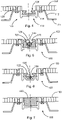
- the mounting rail 100 in an assembled state together with two wall or floor panels 150.
- the panels 150 rest on the support shoulders 115 and leave access to the rail element 120 free.
- the panels 150 can be composite panels, for example. However, the type of panels can be any. Any materials and panels can be used with the mounting rail 100.
- the panels 150 are mechanically coupled to the support shoulder 115, for example connected to the support shoulder 115 with a fastening element 128 in the form of a screw.
- the support shoulders 115 have, at least in sections, a flat contact surface on which the panels 150 rest.
- the support legs 112 extend from the support shoulders 115 away from the panel support surface and are fixed by the mounting surfaces 111 to the support structure 190 of the vehicle.
- the rail member 120 is lowered compared to the upper surface of the panels 150.
- figure 5 shows a variant of the in 4 shown mounting rail with a modified rail element 120. While the rail element 120 in 4 is arranged sunk between the two panels 150, the rail element 120 in figure 5 a greater height and surface of the collar 122 is flush with a top surface 152 of the panels.
- the recording room 124 offers in the variant of figure 5 Space for a line 130 which extends in the longitudinal direction of the rail element 120.
- the line 130 can serve as a signal cable or power cable for electronics, for example, arranged in a seat which is connected to the rail element 120 .
- a load support of an element to be fastened is placed in the lateral indentations 123 of the receiving space 124 so that no mechanical stress is applied to the line 130 .
- FIG. 6 shows another variant for the design of the mounting rail 100.
- the rail member is recessed in relation to the panels 50, but space for a duct 130 is provided by the rail member having a bulge downwards towards the support member.
- the support element 110 is also shaped accordingly in order to create space for the line 130 which is located in the installation space 126 .
- FIG. 7 shows a section of the mounting rail in which no rail element with receiving space is arranged, but a dummy element 160.
- the dummy element can be used in such a region of the mounting rail in which no attachment of external elements is required.
- the dummy element thus ensures that there is no depression at this point in which dirt can accumulate or which could pose a tripping hazard.
- the surface of the dummy element and the upper surface of the panels are at the same level, ie they are flush.
- the mounting rail can consist of several longitudinal sections of support elements 110 and several rail elements arranged in the associated recess, with or without dummy elements. Rail elements made of different materials and of different structure and even Any desired length of dummy members can be used in a support member to compose a mounting rail as a whole as needed.
- the support element 110 encloses an installation space 116 with its support shoulders 115, support legs 112 and the mounting surfaces 111, in which one or more lines 130 can be laid.
- FIG. 1 also shows that the mounting surfaces 111 are connected to a supporting structure 190 of a vehicle by means of fastening elements 128 (screws, bolts, rivets or the like). Fasteners 128 are also used to mechanically couple the panels resting on the support shoulders 115 to the support shoulders.
- the rail element 120 is connected to the support element 110 in a bottom region of its receiving space 124 by means of fastening elements 128 which are arranged at regular or irregular intervals.
- the fastener 128 is in the example 8 a countersunk screw.
- other suitable fastening means such as bolts or rivets can also be used.
- FIG. 9 shows a schematic representation of a rail element 120, the collar of which is provided with a fastening grid.
- the fastening grid is provided in the form of lateral indentations in the collar of the C-profile of the rail element.
- a load support 200 of an external attachable member (not shown) is shown. This load support 200 is inserted into the receiving space 124 of the rail element 120 and fixed at the desired position.
- the mounting rail 100 as described herein may be constructed using a titanium or titanium alloy rail member in a wet area. Titanium has a high specific weight and is also very expensive. For reasons of strength, however, it may be necessary for the rail element (the head of the mounting rail), which is used to hold chair legs or monuments, to consist of a standardized hole pattern made of high-strength material. However, it is not necessary to use this high-strength, heavy and expensive material over the entire cross-section of the mounting rail. Rather, it is sufficient if the rail element meets these requirements.
- the support element can be made of a different material.
- the support element can be made of aluminum or a carbon fiber reinforced plastic, the rail element being connected to the support element with fastening elements, for example titanium bolts.
- the mounting rail described here allows the combined use of carbon fiber reinforced plastics or thermoplastic materials in combination with metal, such as titanium.
- the rail element can even be replaced without having to remove the substructure, i.e. the support element.
- the rail element can also be made of aluminum or include aluminum where lower strength requirements permit. With the mounting rail described here, the use of heavy and expensive materials is reduced to a minimum.
Landscapes
- Engineering & Computer Science (AREA)
- Mechanical Engineering (AREA)
- Aviation & Aerospace Engineering (AREA)
- Transportation (AREA)
- Architecture (AREA)
- Civil Engineering (AREA)
- Structural Engineering (AREA)
- Body Structure For Vehicles (AREA)
Applications Claiming Priority (1)
| Application Number | Priority Date | Filing Date | Title |
|---|---|---|---|
| DE102021104500.2A DE102021104500A1 (de) | 2021-02-25 | 2021-02-25 | Zweiteilige Montageschiene für ein Fahrzeug |
Publications (1)
| Publication Number | Publication Date |
|---|---|
| EP4049932A1 true EP4049932A1 (fr) | 2022-08-31 |
Family
ID=80447716
Family Applications (1)
| Application Number | Title | Priority Date | Filing Date |
|---|---|---|---|
| EP22158130.9A Withdrawn EP4049932A1 (fr) | 2021-02-25 | 2022-02-23 | Rail de montage en deux pièces pour un véhicule |
Country Status (3)
| Country | Link |
|---|---|
| US (1) | US20220267012A1 (fr) |
| EP (1) | EP4049932A1 (fr) |
| DE (1) | DE102021104500A1 (fr) |
Families Citing this family (2)
| Publication number | Priority date | Publication date | Assignee | Title |
|---|---|---|---|---|
| US20260048704A1 (en) * | 2024-08-14 | 2026-02-19 | Jon Montgomery | All-terrain vehicle accessory mounting device |
| DE102024208089B3 (de) * | 2024-08-26 | 2025-09-11 | Dometic Sweden Ab | Befestigungsschiene |
Citations (7)
| Publication number | Priority date | Publication date | Assignee | Title |
|---|---|---|---|---|
| EP1226048A1 (fr) * | 1999-11-01 | 2002-07-31 | Sandströms Transportprodukter AB | Dispositif pour un porte-charge |
| GB2419854A (en) * | 2004-11-06 | 2006-05-10 | Graham Hardman | Vehicle seat anchoarge system |
| US20070041804A1 (en) * | 2004-01-08 | 2007-02-22 | Bayerische Motoren Werke Aktiengessellschaft | Load-bearing rail |
| US7214015B2 (en) * | 2003-05-30 | 2007-05-08 | Airbus Deutschland Gmbh | Apparatus for mounting lashing devices in a freight loading system of a transport conveyance, particularly an aircraft |
| DE102009018487A1 (de) * | 2008-05-02 | 2009-11-12 | Goodrich Corp. | Verfahren und Vorrichtung zum Sichern von Frachtgut in einem Flugzeug |
| US20160114717A1 (en) * | 2013-10-23 | 2016-04-28 | B2B Casuals, Inc. | Cargo Decking Beam System |
| US20180222593A1 (en) * | 2015-10-16 | 2018-08-09 | Airbus Operations Gmbh | Adapter rail system and method for mounting an object to a floor rail in a transportation system |
Family Cites Families (4)
| Publication number | Priority date | Publication date | Assignee | Title |
|---|---|---|---|---|
| DE102006005559B4 (de) | 2006-02-07 | 2007-11-29 | Manfred Berger | Befestigungssystem |
| DE102010037754B4 (de) | 2010-09-23 | 2019-09-19 | allsafe GmbH & Co.KG | Vorrichtung zum Festlegen |
| DE102018123251B4 (de) * | 2018-09-21 | 2021-09-09 | Airbus Operations Gmbh | Schienensystem zum Befestigen von Einbauten in einer Kabine eines Fahrzeugs |
| FR3089949B1 (fr) * | 2018-12-18 | 2021-06-25 | Figeac Aero | Rail de siège et procédé de fabrication |
-
2021
- 2021-02-25 DE DE102021104500.2A patent/DE102021104500A1/de not_active Ceased
-
2022
- 2022-02-23 EP EP22158130.9A patent/EP4049932A1/fr not_active Withdrawn
- 2022-02-24 US US17/679,287 patent/US20220267012A1/en not_active Abandoned
Patent Citations (7)
| Publication number | Priority date | Publication date | Assignee | Title |
|---|---|---|---|---|
| EP1226048A1 (fr) * | 1999-11-01 | 2002-07-31 | Sandströms Transportprodukter AB | Dispositif pour un porte-charge |
| US7214015B2 (en) * | 2003-05-30 | 2007-05-08 | Airbus Deutschland Gmbh | Apparatus for mounting lashing devices in a freight loading system of a transport conveyance, particularly an aircraft |
| US20070041804A1 (en) * | 2004-01-08 | 2007-02-22 | Bayerische Motoren Werke Aktiengessellschaft | Load-bearing rail |
| GB2419854A (en) * | 2004-11-06 | 2006-05-10 | Graham Hardman | Vehicle seat anchoarge system |
| DE102009018487A1 (de) * | 2008-05-02 | 2009-11-12 | Goodrich Corp. | Verfahren und Vorrichtung zum Sichern von Frachtgut in einem Flugzeug |
| US20160114717A1 (en) * | 2013-10-23 | 2016-04-28 | B2B Casuals, Inc. | Cargo Decking Beam System |
| US20180222593A1 (en) * | 2015-10-16 | 2018-08-09 | Airbus Operations Gmbh | Adapter rail system and method for mounting an object to a floor rail in a transportation system |
Also Published As
| Publication number | Publication date |
|---|---|
| US20220267012A1 (en) | 2022-08-25 |
| DE102021104500A1 (de) | 2022-08-25 |
Similar Documents
| Publication | Publication Date | Title |
|---|---|---|
| EP1646555B1 (fr) | Pont a fret et son procede de montage | |
| EP2440457B1 (fr) | Système et procédé de fabrication d'une cabine de véhicule | |
| DE102006019123B4 (de) | Bodenstruktur für einen Rumpf | |
| EP2358593B1 (fr) | Dispositif permettant de fixer un objet sur un rail | |
| DE602005000493T2 (de) | Flugzeugdeck | |
| DE102018122813B4 (de) | Fußbodensystem für ein Fahrzeug | |
| DE102005054890A1 (de) | Befestigungsstruktur zur Fixierung von Inneneinrichtungskomponenten einer Flugzeugpassagierkabine | |
| EP3486161B1 (fr) | Module de plancher pourvu d'élément de plancher monolithique ainsi que zone d'aéronef et aéronef doté d'un module de plancher | |
| EP2563653A1 (fr) | Système de rails, et procédé et système pour monter une pièce dans un avion | |
| DE102018123531B4 (de) | Verfahren zum Installieren von Systemkomponenten in einem Abschnitt eines Flugzeugrumpfs | |
| EP3575176B1 (fr) | Véhicule ferroviaire pourvu de logement de câble | |
| EP4049932A1 (fr) | Rail de montage en deux pièces pour un véhicule | |
| EP3458362B1 (fr) | Système flexible de rail servant à fixer des objets au plancher d'une cabine d'un moyen de transport | |
| DE102015120515A1 (de) | Modulares Schienensystem zum Befestigen von Einrichtungsgegenständen an einem Fußboden einer Fahrzeugkabine | |
| DE102018123251B4 (de) | Schienensystem zum Befestigen von Einbauten in einer Kabine eines Fahrzeugs | |
| DE102018103514A1 (de) | Befestigungssystem zum Befestigen von Einbauten an einer Schiene in einem Fahrzeug | |
| DE102018122958A1 (de) | Bodenbefestigungsbaugruppe | |
| DE102019116891A1 (de) | Hybride Tragschiene zur Aufnahme von Einbauten in einer Kabine eines Fahrzeugs | |
| DE102018110336A1 (de) | Bodenbefestigungsbaugruppe sowie Sitzbefestigungssystem, Sitz und Flugzeug mit einer Bodenbefestigungsbaugruppe | |
| DE102019109149A1 (de) | Schiene zum Befestigen von Ausstattungselementen in Flugzeugen, insbesondere von Sitzen, und Verfahren zur Herstellung | |
| DE102016111983B4 (de) | Modulares Schienensystem | |
| DE102021112580A1 (de) | Frachtladeraum eines Flugzeugs mit Verkleidungselementen und mindestens einem Gehäuseelement | |
| DE102019132513A1 (de) | Bodenelement sowie Luftfahrzeugbereich und Luftfahrzeug mit einem Bodenelement | |
| DE102018123582A1 (de) | Befestigungsvorrichtung für Kabinen und/oder Systemkomponenten, Kabinen- und/oder Systemkomponentenmodul und Verfahren zur Befestigung von Kabinen- und/oder Systemkomponenten | |
| DE102018126012A1 (de) | Schienenanordnung für einen Innenraum eines Flugzeugs |
Legal Events
| Date | Code | Title | Description |
|---|---|---|---|
| PUAI | Public reference made under article 153(3) epc to a published international application that has entered the european phase |
Free format text: ORIGINAL CODE: 0009012 |
|
| STAA | Information on the status of an ep patent application or granted ep patent |
Free format text: STATUS: THE APPLICATION HAS BEEN PUBLISHED |
|
| AK | Designated contracting states |
Kind code of ref document: A1 Designated state(s): AL AT BE BG CH CY CZ DE DK EE ES FI FR GB GR HR HU IE IS IT LI LT LU LV MC MK MT NL NO PL PT RO RS SE SI SK SM TR |
|
| STAA | Information on the status of an ep patent application or granted ep patent |
Free format text: STATUS: THE APPLICATION IS DEEMED TO BE WITHDRAWN |
|
| 18D | Application deemed to be withdrawn |
Effective date: 20230301 |