EP4049946A2 - Dispositif de transport d'objets textiles, de préférence des vêtements, suspendus à des porteurs - Google Patents
Dispositif de transport d'objets textiles, de préférence des vêtements, suspendus à des porteurs Download PDFInfo
- Publication number
- EP4049946A2 EP4049946A2 EP22165858.6A EP22165858A EP4049946A2 EP 4049946 A2 EP4049946 A2 EP 4049946A2 EP 22165858 A EP22165858 A EP 22165858A EP 4049946 A2 EP4049946 A2 EP 4049946A2
- Authority
- EP
- European Patent Office
- Prior art keywords
- driver
- slot
- carriers
- conveyor
- section
- Prior art date
- Legal status (The legal status is an assumption and is not a legal conclusion. Google has not performed a legal analysis and makes no representation as to the accuracy of the status listed.)
- Granted
Links
Images



Classifications
-
- B—PERFORMING OPERATIONS; TRANSPORTING
- B65—CONVEYING; PACKING; STORING; HANDLING THIN OR FILAMENTARY MATERIAL
- B65G—TRANSPORT OR STORAGE DEVICES, e.g. CONVEYORS FOR LOADING OR TIPPING, SHOP CONVEYOR SYSTEMS OR PNEUMATIC TUBE CONVEYORS
- B65G17/00—Conveyors having an endless traction element, e.g. a chain, transmitting movement to a continuous or substantially-continuous load-carrying surface or to a series of individual load-carriers; Endless-chain conveyors in which the chains form the load-carrying surface
- B65G17/20—Conveyors having an endless traction element, e.g. a chain, transmitting movement to a continuous or substantially-continuous load-carrying surface or to a series of individual load-carriers; Endless-chain conveyors in which the chains form the load-carrying surface comprising load-carriers suspended from overhead traction chains
-
- B—PERFORMING OPERATIONS; TRANSPORTING
- B65—CONVEYING; PACKING; STORING; HANDLING THIN OR FILAMENTARY MATERIAL
- B65G—TRANSPORT OR STORAGE DEVICES, e.g. CONVEYORS FOR LOADING OR TIPPING, SHOP CONVEYOR SYSTEMS OR PNEUMATIC TUBE CONVEYORS
- B65G19/00—Conveyors comprising an impeller or a series of impellers carried by an endless traction element and arranged to move articles or materials over a supporting surface or underlying material, e.g. endless scraper conveyors
- B65G19/02—Conveyors comprising an impeller or a series of impellers carried by an endless traction element and arranged to move articles or materials over a supporting surface or underlying material, e.g. endless scraper conveyors for articles, e.g. for containers
- B65G19/025—Conveyors comprising an impeller or a series of impellers carried by an endless traction element and arranged to move articles or materials over a supporting surface or underlying material, e.g. endless scraper conveyors for articles, e.g. for containers for suspended articles
-
- B—PERFORMING OPERATIONS; TRANSPORTING
- B65—CONVEYING; PACKING; STORING; HANDLING THIN OR FILAMENTARY MATERIAL
- B65G—TRANSPORT OR STORAGE DEVICES, e.g. CONVEYORS FOR LOADING OR TIPPING, SHOP CONVEYOR SYSTEMS OR PNEUMATIC TUBE CONVEYORS
- B65G2201/00—Indexing codes relating to handling devices, e.g. conveyors, characterised by the type of product or load being conveyed or handled
- B65G2201/02—Articles
- B65G2201/0229—Clothes, clothes hangers
Definitions
- the invention relates to a device for transporting textile objects hanging on carriers according to the preambles of claims 1 and 5.
- textile objects such as items of clothing are transported along conveyor lines hanging on carriers.
- the textile objects are transported, for example, to laundry treatment facilities, transported away from laundry treatment facilities and/or transported from one laundry machine to the next.
- Known devices of this type have at least one carrying line and at least one conveyor line assigned to it.
- the carriers hang with and/or without the textile objects on the support strand.
- a plurality of drivers spaced apart from one another are arranged on the conveying line.
- the conveyor line has a drive.
- the carriers can be moved further from the conveyor line in the transport direction, with these carriers being able to be moved along the carrier line in the transport direction by means of a targeted coupling of the carriers to certain carriers.
- the respective conveyor line usually has a conveyor chain on which the carriers are pivotably mounted in order to be coupled to specific carriers in a targeted manner to be able to.
- the carriers run over the front carrier.
- the object of the invention is to provide a device for transporting textile objects, preferably items of clothing, which are suspended from carriers and which is easy to assemble.
- a device for solving the problem mentioned at the outset has the features of claim 1 .
- the snap-in attachment of the drivers to the support bolts of the respective conveying line results in an easy connection of the drivers to the at least one conveying line.
- a latching connection of the drivers to the conveyor line is preferably achieved by attaching each driver to at least one support bolt on the conveyor line in a direction transverse to the longitudinal central axis of the at least one support bolt.
- the driver is preferably provided with at least one slot open on one side.
- the at least one slot which is open on one side has a starting section which starts at the open end and is narrower than the diameter of the supporting bolt assigned to it.
- the starting area of the slot is only slightly narrower than the diameter of the supporting bolt assigned to it, to such an extent that the respective slot can be snapped on to the supporting bolt of the conveyor line assigned to it, expanding elastically. This enables a simple, tool-free connection of the respective driver to the support bolt of the conveyor line assigned to it, with the respective driver remaining reliably held on the support bolt assigned to it during operation of the device due to the narrower initial section, without being able to detach itself from the support bolt.
- each driver or its driver body in particular the single slot or the respective slot in the same, provides that an end region of the at least one slot, which is closed at the end and adjoins the narrower starting section, is wider than the starting section.
- the end area preferably has a width that is greater in this way than the initial section, which is slightly greater than the diameter of the supporting bolt assigned to it.
- each driver is held and/or mounted on the conveyor line with two spaced, parallel support bolts, the displaceability of at least one slot relative to the support bolt of the conveyor line assigned to it also ensures free pivoting of the respective driver, although the pivot angle is determined by the two is limited in each case to a supporting bolt slipped slots of the driver.
- a further device for solving the problem mentioned at the outset which can also be preferred developments of the devices described above, has the features of claim 5 . Accordingly, it is provided that the preferably single spring for pivoting the respective driver in one direction, preferably in the direction of the support strand and/or the carrier suspended thereon, can be plugged into a laterally open slot in the respective driver or driver body.
- the respective tongue is positively and/or non-positively fixed in the slot by thermal deformation of at least one accumulation of material and/or at least one bead in the region of the slot, preferably at the edge of the slot. This ensures a simple but reliably fixed connection of the spring to the respective driver or its driver body.
- the respective spring is in the form of a leaf spring.
- the leaf spring has an angled end area at one end that is inserted into the slot of the driver. This end area prevents the end area of the leaf spring located in the slot of the driver from being pulled out of the slot.
- the leaf spring is secured with its end region assigned to the respective driver in the longitudinal and transverse direction of the slot accommodating the leaf spring with its end region in and on the driver, in particular its driver body.
- the carriers and/or their carrier bodies are formed from several, preferably two, carrier parts and these carrier parts are connected by at least one damping seam.
- the damping seam preferably serves to dampen sound and/or vibrations.
- each driver part is preferably made to have a thickness which corresponds to the thickness of the driver. Both driver parts are about the same thickness. As a result, the respective damping seam can extend over the entire thickness of the driver. This leads to a reliable connection of the driver parts through the damping seam. In addition, a continuous damping seam over the entire thickness of the respective driver and its driver parts can have the largest possible contact surface to the driver parts to be connected.
- the cover surfaces preferably the front and rear sides of the driver body, are flush with the surface.
- the edges of the driver parts delimiting the seam or seams have such a, preferably similar, course that leads to a continuous, uninterrupted gap between adjacent driver parts, which can be filled by the respective damping seam .
- the cross-section of the damping seam is preferably the same over its entire length.
- the driver parts can thus be connected simply and effectively in that the gap between the adjacent edges of the driver parts is filled, preferably completely, by the material of the at least one damping seam. Due to the at least one damping seam, the driver parts retain their independence after their connection in terms of acoustics, at least for the most part, in that the driver parts are mechanically connected by the at least one damping seam, but remain at least largely separate acoustically.
- the at least one damping seam for connecting the driver parts extends uninterruptedly and continuously over the entire length of the gap. Because the gap runs continuously between two different, preferably opposite Edges and / or corners of the driver extends, receives the respective damping seam, preferably single damping seam, a maximum possible length.
- the or the respective, preferably only, seam of the respective driver and/or the gap to be filled by the respective seam between the driver parts has a tortuous, labyrinthine and/or meandering course. This leads to an increase in the length of the respective damping seam.
- Another advantageous embodiment option of the device provides for forming the at least one damping seam from an elastomer.
- the elastomer is preferably one that is softer than the material of the driver parts.
- the driver parts are preferably also made of a thermoplastic material, in particular polyamide.
- the elastomer of the at least one damping seam is preferably a thermoplastic elastomer. This makes it possible not only to produce the driver parts of the driver in the injection molding process, but also in what is known as two-component injection molding to produce the at least one damping seam in the injection molding process, with the connection of the driver parts occurring during the production of the at least one damping seam in the injection molding process.
- This connection is created by the fact that after the previously performed injection molding of the driver parts, during subsequent injection molding of the at least one damping seam, the at least one gap between the driver parts to be connected is filled with the material of the at least one damping seam that has been made flowable by thermal heating for injection molding, and during Cooling and solidification of the material of the at least one damping seam, the material of the same bonded to the edge surfaces of both driver parts delimiting the gap.
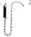
- the 1 and 2 show an example of a possible conveyor section 10 of the device.
- Textile objects hanging on carriers 11, preferably so-called shaped parts such as items of clothing, work clothing or the like, can be transported along the conveyor line 10 to different work stations, processing stations and/or treatment stations.
- the carriers 11 are shown, which can be designed, for example, as hanger arms that can be folded in and out and/or transport hangers that have trouser clips.
- Textile objects, such as primarily items of clothing, hung on or on the supports 11, in particular transport hangers, are not shown in the figures.
- the conveyor line 10 has three conveyor line sections 13, 14 and 15.
- the invention is not limited to the 1 Conveyor section 10 shown, in particular its course, restricted.
- the conveyor section 10 can have any course.
- the conveyor line 10 can also have more or fewer than three conveyor line sections 13 to 15 .
- the first conveyor line section 13 of the conveyor line 10 serves to transport items of clothing to be treated to a tunnel finisher 16 for smoothing the items of clothing.
- Items of clothing smoothed in the tunnel finisher 16 are transported along the second conveyor section 14 from the tunnel finisher 16 to a folding machine 17 .
- the finished garments are preferably automatically removed from the respective carrier 11.
- the empty carriers 11 are then transported along the third conveyor section 15 from the folding machine 17 to a loading station 18 where they are again loaded with (other) garments to be treated. In the exemplary embodiment shown, this is done by one person 19 or, if appropriate, by a number of people.
- the carrier 11 can also be loaded automatically with items of clothing at the loading station 18 . From the loading station 18 , the carriers 11 , which have again been loaded with items of clothing to be treated, are successively fed to the start of the conveyor section 13 .
- the invention is also suitable for conveyor lines that do not form a closed circuit and also for conveyor lines that do not link tunnel finishers 16 and folding machines 17 to one another, but are used to transport items of clothing or other textile objects assigned to carriers 11 to at least one other laundry machine and/or from this machine away or to link any other laundry machines, even more than two laundry machines.
- the conveyor section 10 is formed from at least one continuous conveyor.
- each conveyor line section 13, 14 and 15 is formed from its own, preferably independent, continuous conveyor.
- the respective continuous conveyor of the conveyor line 10 or the conveyor line sections 13, 14 and 15 has a support line 20 and a parallel conveyor line 21 extending at a small distance across the same.
- Each support line 20 and each conveyor line 21 run parallel one above the other along the transport direction 12 the conveyor line 10 or its conveyor line sections 13, 14 and 15.
- Both the support line 20 and the conveyor line 21 are arranged in a stationary manner under a ceiling of the laundry and/or on columns fastened to the floor of the laundry.
- the course of the respective carrying line 20 and the conveyor line 21 assigned to it corresponds to the course of the conveying line 10 or the conveying line sections 13, 14 and 15.
- the respective support strand 20 can be designed as a tube with a preferably round cross section, but it can also have a profiled cross section that does not necessarily have to be tubular.
- the decisive factor is that the respective support strand 20 is designed or profiled in such a way that the carrier 11, both loaded and unloaded carrier 11, can slide along with their upper hooks 22 on the respective preferably horizontally running support strand 20.
- the carriers 11 with the hooks 22 are on the respective support strand 20 attached or hung on the respective support strand 20. In this way, the carriers 11 hang down from their hooks 22 on the respective carrying strand 20, with the items of clothing to be treated and transported further hanging down from the respective carrier 11 in turn.
- the respective conveyor line 21 of the conveyor line 10 or the respective conveyor line section 13, 14 and 15 has a stationary sliding line 23 and a conveyor chain 24 that can be driven in a revolving manner.
- the conveyor chain 24 runs along or in the sliding line 23 and is guided by the sliding line 23 in the process.
- the conveyor chain 24 is designed as a roller chain with chain links 26 connected in an articulated manner by means of bolts and sleeves mounted thereon.
- the conveyor chain 24 is aligned in such a way that its bolts 25 connecting the individual chain links 26 run vertically.
- the chain links 26 of the conveyor chain 24 are assigned to the sliding strand 23 in a standing position.
- Successive carriers 27 are connected to the conveyor chain 24 of the conveyor line 21 at equal intervals. All drivers 27 are of the same design. Each driver 27 is movably connected to a chain link 26 of the conveyor chain 24 by means of a fastening bracket 28 . In the exemplary embodiment shown, not every chain link 26 carries a driver 27, but only every fifth chain link 26. However, the invention should not be limited to this. The distance between consecutive identical drivers 27 can be a larger or smaller number of chain links 26 .
- Each fastening bracket 28 is fastened with a shorter leg under the relevant chain link 26 of the conveyor chain 24, for example with two parallel spaced bolts 25 of the respective chain link 26.
- a respective one is below the conveyor chain 24 arranged driver 27 movably connected.
- the longer leg of each mounting bracket 28, which is aligned in the transport direction 12 and lies in a vertical plane, has two spaced support bolts 29. Both support bolts 29 protrude from the same side of the longer leg of the mounting bracket 28, namely horizontally and transversely to the transport direction 12 running.
- the mounting brackets 28 can also be U-shaped in cross section with two parallel, vertical, longer legs, between which a rear part of the respective driver 27 is fastened. Then the two supporting bolts 29 extend for the respective driver 27 directed horizontally from a longer vertical leg to the spaced-apart, adjacent longer leg.
- Each of the identically designed drivers 27 has a driver body 30 made up of two driver parts 31 and 32 and a damping seam 33 connecting them.
- the driver 27 shown here also has a spring 34.
- the driver 27 can also consist of more than two driver parts 31 and 32 exist. Likewise, the driver 27 can have more than one damping seam 33 connecting the driver parts.
- the driver 27 can also have several possibly different springs.
- the cam body 30 is formed in an upright plate manner.
- the driver body 30 has side surfaces lying in two parallel, upright planes, which form a front side 45 and a back side 36 .
- opposite depressions 37 are provided in the front side 35 and in the rear side 36 in order to reduce the material.
- the driver body 30 is surrounded by an edge 30 which is interrupted by gaps 39 and slots 40, 41 and 42 in the exemplary embodiment shown.
- the slot 40 in the driver body 30 is assigned to a tapered end region of the driver 27 .
- the slot 40 is open on the underside of the driver body 30 by interrupting the edge 38 of the driver body 30 here.
- the elongated slot 40 runs slightly relative to a vertical, namely by 10° to 30°, in particular 15°. This inclination is such that the slot 40 runs outwards, starting from its open end to the closed, approximately semicircular end, ie towards the tapered end of the driver 27 .
- the slot 40 has a width that is slightly larger than the diameter of the hooks 22 of the carrier 11.
- the slot 40 of the respective carrier 27 can be coupled to the respective carrier 11 by the hook 22 of the respective carrier 11 being inserted into the slot 40 engages or the slot 40 partially encompasses the hook 22 from above ( 3 ).
- the plane of the carrier 11 runs transversely to the plane of the respective driver 27.
- Both slits 41 and 42 are arranged on the end region of the driver 27 opposite the slot 40 .
- Both slits 41 and 42 start from an upper, preferably rectilinear and/or horizontal section of the peripheral edge, which is however interrupted by the slits 40, 41 and 42 38 of cam body 30.
- Slots 41 and 42 are associated with cam portion 31 as opposed to slot 40 associated with cam portion 32.
- Both slots 41, 42 run parallel to one another at an angle of approximately 45°.
- the angle can be up to 30° larger or smaller.
- the inclination of the slots 41 and 42 is such that their closed ends point towards the adjacent vertical portion of the rim 38 .
- the slots 41 and 42 have an upper starting section 45 starting from the approximately horizontal section of the edge 38 of the driver body 30 .
- the initial section 45 of each slot 41 and 42 also has a width that is slightly smaller than the diameter of the support bolt 29, with which the respective driver 27 is attached to a chain link 26 of the conveyor chain 24, including the attachment bracket 28.
- each initial section 45 is so smaller than the same diameter of the supporting bolts 29 that each driver 29 can be pushed onto the two identical supporting bolts 29 assigned to it in a latching manner, with elastic widening of the slots 41 and 42. This makes it easy to attach the respective driver without tools 27 with its slots 41 and 42 on the two support bolts 29 on the mounting bracket 28 of the respective chain link 26 of the conveyor chain 21 is possible. By plugging the drivers 27 with the slots 41 and 42 onto the support bolts 29, the drivers 27 are fixed on the support bolts 29 in such a way that they can no longer detach themselves from them.
- An end section following the beginning section 45 of each slot 41 and 42 has a cylindrical widening 46.
- the cylindrical widening 46 of the front slot 41 is larger than that of the rear slot 42.
- the cylindrical widening 46 is only so much larger than the diameter of the its associated support bolt 29, which the respective driver 27 can be rotated about the support bolt 29 in the cylindrical widening 46 at the closed end of the slot 42 about the longitudinal central axis of the supporting bolt 29.
- the cylindrical widening 46 at the end of the front slot 41 is larger than the cylindrical Widening 46 at the end of the slot 42.
- the cylindrical widening 46 at the end of the slot 41 is preferably 30% to 50% larger than the cylindrical widening 46 at the end of the slot 42.
- the respective driver 27 can move around the support bolt 29 in the rear slot 42 are pivoted to a limited extent, with the larger cylindrical Aufw duct 46 at the end of the foremost slot 41 limits the pivoting path or pivoting angle of the respective driver 27 about the support bolt 29 in the rear slot 42.
- the two driver parts 31 and 32 are the same width, but have different bases.
- the base areas of the driver parts 31 and 32 are divided in such a way that adjacent inner edges 43, 44, which are not involved in the formation of the outer peripheral edge 38 of the driver body 30, do not abut one another when the driver parts 31, 32 are assembled, but are equally spaced apart from each other Formation of the gap 39 between the driver parts 31, 32.
- the gap 39 is thus delimited by the inner edge 43 of the driver part 31 and by the inner edge 44 of the driver part 32.
- the gap 39 has a width that preferably corresponds to the greatest thickness of the driver body 30 . However, it is conceivable that the width of the gap 39 is up to 40%, in particular up to 25%, larger or smaller than the maximum thickness of the driver body 30.
- the gap 39 runs continuously between different sections of the outer edge 39 of the driver body 30.
- the gap 39 starts at a top, preferably straight section of the edge 38 of the driver body 30 and ends in a preferably straight lateral section of the edge 38 of the Driver body 30.
- This preferably approximately vertical or slightly inclined portion of the edge 38 is located on that side of the driver body 30, which are associated with the two spaced slots 40 and 41.
- the gap 39 does not run along the shortest route from one section to the other section of the edge 38 of the driver body 30, but in a serpentine and/or meandering manner. As a result, the length of the gap 39 in the driver body 30 is increased.
- the gap 39 has an approximately S-shaped, meandering part, starting from the upper and approximately horizontally directed section of the edge 38 of the driver body 30 . This is followed by a straight area of the gap 39 that is slightly bent in the exemplary embodiment shown and ends in an approximately vertical lateral section of the edge 38 of the driver body 30 . This slightly kinked elongate portion of gap 39 is approximately as long as the S-shaped initial portion or portion of gap 39.
- the two assembled driver bodies 30 are connected by the single damping seam 33.
- This connection takes place in the manner of a butt weld seam.
- This butt weld seam is designed in the manner of an I-seam, which completely or at least largely fills the gap 39 and extends continuously from the flat front side 35 to the flat back side 36 of the driver body 30 .
- the damping seam 33 After connecting the driver parts 31 and 32 by the damping seam 33 creates the permanently one-piece driver body 30, the damping seam 33 in the region of the gap 39 contributing to the formation of a part of the front side 35 and the rear side 36 of the driver body 30.
- the driver body 30 of each driver 27 is formed from two different materials, in particular plastic or elastomer.
- the driver parts 31 and 32 are likewise formed from a thermoplastic material, in particular polyamide.
- the damping seam 33 is formed from an elastomer that is softer than the material of the driver parts 31 and 32.
- the material of the damping seam 33 is preferably a thermoplastic elastomer.
- the damping seam 33 As a result of the formation of the damping seam 33 from an elastomer, in particular a thermoplastic elastomer, it is softer than the plastic from which the driver parts 31, 32 are formed. As a result, the damping seam 33 has a noise and/or vibration damping effect. The consequence of this is that the two driver parts 31 and 32 are separated from one another in terms of vibration and/or acoustics.
- the spring 34 of the driver 27 shown is an approximately U-shaped pre-bent leaf spring.
- the width of the leaf spring forming the spring 34 is slightly less than the width or thickness of the driver 27.
- At least one edge of the spring 34 is set back slightly in relation to the front side 35 of the driver body 30, preferably also in relation to the rear side 36.
- the spring 34 which is designed as a leaf spring, has two legs 47 and 48, which are connected in one piece by a semicircular web 49, because of its U-shaped prebend.
- the two legs 47 and 48 of unequal length do not run completely parallel to one another; rather they diverge slightly towards their free ends.
- the longer leg 48 and the web 49 of the spring 34 designed as a leaf spring are located outside of the driver body 30 of the driver 27.
- the shorter leg 47 of the spring 34 is located in a groove 50 that is only open laterally towards the rear side 36 of the driver body 30
- the front side 34 of the driver body 30 is closed by the groove 50 so that it is a bag-like groove 50 .
- the groove 50 is open towards a vertical end section of the edge 38 of the driver body 30 .
- the Groove 50 is provided with a blind hole-like widening 51 at its opposite end lying in the interior of driver part 31 . Between this widening 51 and the open end of the groove 50 there are two preferably identical blind holes 52. The blind holes 52 are spaced apart from one another and also from the widening 51 and the open end of the groove 50 at a distance.
- the accumulations of material are provided on both sides next to the groove 50 between two adjacent blind holes 52 and a blind hole 52 and the widening 51, which do not (yet) constrict the groove 50 open to the rear side 36 of the driver body 30 (rear).
- the accumulations of material are preferably four point-like projections 54 protruding from the rear side 36 of the driver part 31 of the driver body 30.
- the spring 34 After the spring 34 has been pushed transversely through the rear side 36 of the driver body 30 with its shorter leg 47 into the groove 50, the spring 34 is secured by lateral movement out of the groove 50 open towards the rear side 36 by softening and subsequent plastic deformation of the Projections 54. This can be done, for example, by ultrasonic welding. In this way, the groove 50 is partially closed.
- the shorter leg 47 of the spring 34 pushed laterally into the groove 50 has an angled end 55 which is supported in the widening 51 .
- the long leg 48 of the spring 34 designed as a leaf spring, which is located outside the driver body 30, runs slightly antiparallel to the section of the edge 38 of the driver body 30 that overlaps it, in such a way that when the spring 34 is unloaded, the leg 48 is at a distance towards its end increased towards the edge 38.
- a short end area of the same, starting from the free end of the longer leg 48, is slightly bent in the direction of the edge 38 of the driver body 30, so that this end area 56 approaches the edge 38 of the driver body 30 again towards the free end of the longer leg 48. This prevents the end or end area 56 of the longer leg 48 of the spring 34 that is exposed above the driver body 30 from getting caught on the sliding line 23 of the conveying line 21 .
- FIG 3 shows parts of a section of the conveyor line 10, for example the conveyor line section 15.
- the carriers 27 attached to the conveyor chain 24 are moved further in the transport direction 12 by the conveyor chain 24, which is driven in rotation.
- the prestressed spring 34 pivots the driver 27 in question with its rear end having the hook-like slot 40 downwards.
- the hook-like slot 40 on the rear side of the driver 27 in question hooks 22 of the last carrier 11 of the package of carriers 11 that follow one another in close succession, seen in the transport direction 12 .
- This carrier 11 is now taken along the conveying path 10 in the transport direction 12 by the driver 27 hooked to it and thereby transported further.
- This pivoting movement of the carrier is generated by the sloping lower section of the edge 38 of the carrier body 30 sliding along the lifting bevel 57 over the hook 22 of the subsequent carrier 12 in the store 58, viewed in the transport direction 12.
- the carrier 27 then slides over all the hooks 22 the carrier 12 in the store 58 away until the driver 27 in question is coupled with its hook-like slot 40 again to the last carrier 11 in the store 58 seen in the transport direction 12 .
Landscapes
- Engineering & Computer Science (AREA)
- Mechanical Engineering (AREA)
- Chain Conveyers (AREA)
- Intermediate Stations On Conveyors (AREA)
Applications Claiming Priority (2)
| Application Number | Priority Date | Filing Date | Title |
|---|---|---|---|
| DE102020123445.7A DE102020123445A1 (de) | 2020-09-08 | 2020-09-08 | Vorrichtung zum Transport von an Trägern hängenden textilen Gegenständen, vorzugsweise Bekleidungsstücken |
| EP21194653.8A EP3964457B1 (fr) | 2020-09-08 | 2021-09-02 | Dispositif de transport des objets textiles suspendus à des supports, de préférence vêtements |
Related Parent Applications (2)
| Application Number | Title | Priority Date | Filing Date |
|---|---|---|---|
| EP21194653.8A Division-Into EP3964457B1 (fr) | 2020-09-08 | 2021-09-02 | Dispositif de transport des objets textiles suspendus à des supports, de préférence vêtements |
| EP21194653.8A Division EP3964457B1 (fr) | 2020-09-08 | 2021-09-02 | Dispositif de transport des objets textiles suspendus à des supports, de préférence vêtements |
Publications (3)
| Publication Number | Publication Date |
|---|---|
| EP4049946A2 true EP4049946A2 (fr) | 2022-08-31 |
| EP4049946A3 EP4049946A3 (fr) | 2022-09-14 |
| EP4049946B1 EP4049946B1 (fr) | 2024-04-17 |
Family
ID=77627067
Family Applications (2)
| Application Number | Title | Priority Date | Filing Date |
|---|---|---|---|
| EP21194653.8A Active EP3964457B1 (fr) | 2020-09-08 | 2021-09-02 | Dispositif de transport des objets textiles suspendus à des supports, de préférence vêtements |
| EP22165858.6A Active EP4049946B1 (fr) | 2020-09-08 | 2021-09-02 | Dispositif de transport d'objets textiles, de préférence des vêtements, suspendus à des porteurs |
Family Applications Before (1)
| Application Number | Title | Priority Date | Filing Date |
|---|---|---|---|
| EP21194653.8A Active EP3964457B1 (fr) | 2020-09-08 | 2021-09-02 | Dispositif de transport des objets textiles suspendus à des supports, de préférence vêtements |
Country Status (3)
| Country | Link |
|---|---|
| EP (2) | EP3964457B1 (fr) |
| DE (1) | DE102020123445A1 (fr) |
| DK (2) | DK3964457T3 (fr) |
Cited By (1)
| Publication number | Priority date | Publication date | Assignee | Title |
|---|---|---|---|---|
| WO2025082684A1 (fr) * | 2023-10-16 | 2025-04-24 | On Time Systems GmbH | Système transporteur et procédé de transport d'éléments transporteurs le long d'un rail de transport |
Families Citing this family (1)
| Publication number | Priority date | Publication date | Assignee | Title |
|---|---|---|---|---|
| DE102024104495B3 (de) | 2024-02-19 | 2025-01-02 | Fintec Textilpflegesysteme Gmbh | Fördereinrichtung zum Transport verschiebbarer Wäschebügel |
Family Cites Families (11)
| Publication number | Priority date | Publication date | Assignee | Title |
|---|---|---|---|---|
| DE7416361U (de) | 1974-05-10 | 1977-12-08 | O & K Orenstein & Koppel Ag Werk Luebeck, 2400 Luebeck | Dichtung fuer kettengelenke insbesondere fuer eimer- oder becherketten |
| US4232783A (en) | 1979-03-19 | 1980-11-11 | Westinghouse Electric Corp. | Step link for transportation apparatus |
| DE9202325U1 (de) * | 1992-02-22 | 1992-04-16 | psb GmbH Förderanlagen und Lagertechnik, 6780 Pirmasens | Kupplung für Schleppkreisförderer |
| DE9209392U1 (de) | 1992-07-13 | 1993-09-02 | WF Logistik GmbH, 86899 Landsberg | Förderer |
| DE29621786U1 (de) | 1996-12-16 | 1997-03-27 | PEP Fördertechnik GmbH, 33609 Bielefeld | Stauklinkenförderer |
| US6138820A (en) * | 1998-05-15 | 2000-10-31 | Westar Mfg. Corp. | Conveyor chain link |
| DE29915523U1 (de) | 1999-09-03 | 2000-02-24 | PEP Fördertechnik GmbH, 33609 Bielefeld | Klinke für Klinkenförderer |
| US6446790B1 (en) | 2001-02-14 | 2002-09-10 | Omega Solutions, Inc. | Link for sharp chain conveyor |
| ES2690086T3 (es) | 2013-06-24 | 2018-11-19 | Dematic Logistics Gmbh | Dispositivo de transporte y un método de posicionamiento de un adaptador de soporte en una cadena de transporte |
| DE102014105767B4 (de) * | 2014-04-24 | 2018-01-04 | Fintec Textilpflegesysteme Gmbh | Schleppklinke für einen Klinkenförderer |
| CN208814034U (zh) * | 2018-09-30 | 2019-05-03 | 昆山金晁鑫自动化有限公司 | 悬挂运输系统拖钩装置 |
-
2020
- 2020-09-08 DE DE102020123445.7A patent/DE102020123445A1/de not_active Withdrawn
-
2021
- 2021-09-02 EP EP21194653.8A patent/EP3964457B1/fr active Active
- 2021-09-02 DK DK21194653.8T patent/DK3964457T3/da active
- 2021-09-02 EP EP22165858.6A patent/EP4049946B1/fr active Active
- 2021-09-02 DK DK22165858.6T patent/DK4049946T3/da active
Cited By (1)
| Publication number | Priority date | Publication date | Assignee | Title |
|---|---|---|---|---|
| WO2025082684A1 (fr) * | 2023-10-16 | 2025-04-24 | On Time Systems GmbH | Système transporteur et procédé de transport d'éléments transporteurs le long d'un rail de transport |
Also Published As
| Publication number | Publication date |
|---|---|
| DK4049946T3 (da) | 2024-07-08 |
| DE102020123445A1 (de) | 2022-03-10 |
| EP3964457B1 (fr) | 2024-08-21 |
| EP4049946B1 (fr) | 2024-04-17 |
| EP4049946A3 (fr) | 2022-09-14 |
| DK3964457T3 (da) | 2024-11-11 |
| EP3964457A1 (fr) | 2022-03-09 |
Similar Documents
| Publication | Publication Date | Title |
|---|---|---|
| EP3028961B1 (fr) | Sac de transport pour une marchandise dans une installation de transport de marchandise suspendue | |
| EP3380416B1 (fr) | Sac de transport et procédé de remplissage et de vidage d'un tel sac de transport | |
| EP3250484B1 (fr) | Dispositif de transport sous la forme d'un convoyeur aérien | |
| DE60106099T2 (de) | Stützschiene für die gebogene Sektion einer Hängebahn | |
| EP3619147B1 (fr) | Dispositif de chargement de sacs de transport | |
| EP2110211B1 (fr) | Cadre de support pour robots | |
| EP1977984A1 (fr) | Dispositif d'acheminement pour produits en vrac | |
| DE202017106993U1 (de) | Transporttasche zum Transportieren einer Ware in einer Hängewarenförderanlage | |
| EP4049946B1 (fr) | Dispositif de transport d'objets textiles, de préférence des vêtements, suspendus à des porteurs | |
| WO2018078098A1 (fr) | Procédé et dispositif pour ouvrir un sac de transport | |
| DE202006003445U1 (de) | Fördervorrichtung für stoßempfindliche Produkte | |
| EP0711715A2 (fr) | Transporteur à godets | |
| DE2310356A1 (de) | Foerdergestell | |
| DE10309127A1 (de) | Vorrichtung zum Transportieren und/oder Aufbewahren von Stückgut | |
| EP2597059B2 (fr) | Dispositif de transport suspendu | |
| DE9209392U1 (de) | Förderer | |
| EP0598325B1 (fr) | Porte-chaussures | |
| EP4332025B1 (fr) | Dispositif pour le transport de produits de récolte | |
| WO2019197552A1 (fr) | Unité tablier-cribleur d'une récolteuse ou d'une unité de transport de produits de récolte | |
| DE3530069C2 (de) | Vorrichtung mit einer Fördereinrichtung | |
| DE19914025A1 (de) | Vorrichtung für die Aufbewahrung und den Transport von Stückgut sowie Verfahren zur Herstellung einer solchen Vorrichtung | |
| DE202019101032U1 (de) | Vorrichtung zum Trocknen von Biomasse und Kompaktanlage zum Trocknen von Biomasse | |
| DE9204632U1 (de) | Endloshängeförderer | |
| DE3347796C2 (fr) | ||
| EP2100748B1 (fr) | Dossier suspendu |
Legal Events
| Date | Code | Title | Description |
|---|---|---|---|
| PUAI | Public reference made under article 153(3) epc to a published international application that has entered the european phase |
Free format text: ORIGINAL CODE: 0009012 |
|
| STAA | Information on the status of an ep patent application or granted ep patent |
Free format text: STATUS: THE APPLICATION HAS BEEN PUBLISHED |
|
| PUAL | Search report despatched |
Free format text: ORIGINAL CODE: 0009013 |
|
| AC | Divisional application: reference to earlier application |
Ref document number: 3964457 Country of ref document: EP Kind code of ref document: P |
|
| AK | Designated contracting states |
Kind code of ref document: A2 Designated state(s): AL AT BE BG CH CY CZ DE DK EE ES FI FR GB GR HR HU IE IS IT LI LT LU LV MC MK MT NL NO PL PT RO RS SE SI SK SM TR |
|
| AK | Designated contracting states |
Kind code of ref document: A3 Designated state(s): AL AT BE BG CH CY CZ DE DK EE ES FI FR GB GR HR HU IE IS IT LI LT LU LV MC MK MT NL NO PL PT RO RS SE SI SK SM TR |
|
| RIC1 | Information provided on ipc code assigned before grant |
Ipc: B65G 19/02 20060101ALI20220808BHEP Ipc: B65G 17/20 20060101AFI20220808BHEP |
|
| STAA | Information on the status of an ep patent application or granted ep patent |
Free format text: STATUS: REQUEST FOR EXAMINATION WAS MADE |
|
| 17P | Request for examination filed |
Effective date: 20221027 |
|
| RBV | Designated contracting states (corrected) |
Designated state(s): AL AT BE BG CH CY CZ DE DK EE ES FI FR GB GR HR HU IE IS IT LI LT LU LV MC MK MT NL NO PL PT RO RS SE SI SK SM TR |
|
| GRAP | Despatch of communication of intention to grant a patent |
Free format text: ORIGINAL CODE: EPIDOSNIGR1 |
|
| STAA | Information on the status of an ep patent application or granted ep patent |
Free format text: STATUS: GRANT OF PATENT IS INTENDED |
|
| INTG | Intention to grant announced |
Effective date: 20231124 |
|
| GRAS | Grant fee paid |
Free format text: ORIGINAL CODE: EPIDOSNIGR3 |
|
| GRAA | (expected) grant |
Free format text: ORIGINAL CODE: 0009210 |
|
| STAA | Information on the status of an ep patent application or granted ep patent |
Free format text: STATUS: THE PATENT HAS BEEN GRANTED |
|
| AC | Divisional application: reference to earlier application |
Ref document number: 3964457 Country of ref document: EP Kind code of ref document: P |
|
| AK | Designated contracting states |
Kind code of ref document: B1 Designated state(s): AL AT BE BG CH CY CZ DE DK EE ES FI FR GB GR HR HU IE IS IT LI LT LU LV MC MK MT NL NO PL PT RO RS SE SI SK SM TR |
|
| REG | Reference to a national code |
Ref country code: GB Ref legal event code: FG4D Free format text: NOT ENGLISH |
|
| REG | Reference to a national code |
Ref country code: CH Ref legal event code: EP |
|
| REG | Reference to a national code |
Ref country code: DE Ref legal event code: R096 Ref document number: 502021003420 Country of ref document: DE |
|
| REG | Reference to a national code |
Ref country code: IE Ref legal event code: FG4D Free format text: LANGUAGE OF EP DOCUMENT: GERMAN |
|
| P01 | Opt-out of the competence of the unified patent court (upc) registered |
Effective date: 20240416 |
|
| REG | Reference to a national code |
Ref country code: DK Ref legal event code: T3 Effective date: 20240704 |
|
| REG | Reference to a national code |
Ref country code: LT Ref legal event code: MG9D |
|
| REG | Reference to a national code |
Ref country code: NL Ref legal event code: MP Effective date: 20240417 |
|
| PG25 | Lapsed in a contracting state [announced via postgrant information from national office to epo] |
Ref country code: NL Free format text: LAPSE BECAUSE OF FAILURE TO SUBMIT A TRANSLATION OF THE DESCRIPTION OR TO PAY THE FEE WITHIN THE PRESCRIBED TIME-LIMIT Effective date: 20240417 |
|
| PG25 | Lapsed in a contracting state [announced via postgrant information from national office to epo] |
Ref country code: NL Free format text: LAPSE BECAUSE OF FAILURE TO SUBMIT A TRANSLATION OF THE DESCRIPTION OR TO PAY THE FEE WITHIN THE PRESCRIBED TIME-LIMIT Effective date: 20240417 |
|
| PG25 | Lapsed in a contracting state [announced via postgrant information from national office to epo] |
Ref country code: IS Free format text: LAPSE BECAUSE OF FAILURE TO SUBMIT A TRANSLATION OF THE DESCRIPTION OR TO PAY THE FEE WITHIN THE PRESCRIBED TIME-LIMIT Effective date: 20240817 |
|
| PG25 | Lapsed in a contracting state [announced via postgrant information from national office to epo] |
Ref country code: BG Free format text: LAPSE BECAUSE OF FAILURE TO SUBMIT A TRANSLATION OF THE DESCRIPTION OR TO PAY THE FEE WITHIN THE PRESCRIBED TIME-LIMIT Effective date: 20240417 |
|
| PG25 | Lapsed in a contracting state [announced via postgrant information from national office to epo] |
Ref country code: HR Free format text: LAPSE BECAUSE OF FAILURE TO SUBMIT A TRANSLATION OF THE DESCRIPTION OR TO PAY THE FEE WITHIN THE PRESCRIBED TIME-LIMIT Effective date: 20240417 Ref country code: FI Free format text: LAPSE BECAUSE OF FAILURE TO SUBMIT A TRANSLATION OF THE DESCRIPTION OR TO PAY THE FEE WITHIN THE PRESCRIBED TIME-LIMIT Effective date: 20240417 |
|
| PG25 | Lapsed in a contracting state [announced via postgrant information from national office to epo] |
Ref country code: GR Free format text: LAPSE BECAUSE OF FAILURE TO SUBMIT A TRANSLATION OF THE DESCRIPTION OR TO PAY THE FEE WITHIN THE PRESCRIBED TIME-LIMIT Effective date: 20240718 |
|
| PG25 | Lapsed in a contracting state [announced via postgrant information from national office to epo] |
Ref country code: PT Free format text: LAPSE BECAUSE OF FAILURE TO SUBMIT A TRANSLATION OF THE DESCRIPTION OR TO PAY THE FEE WITHIN THE PRESCRIBED TIME-LIMIT Effective date: 20240819 |
|
| PG25 | Lapsed in a contracting state [announced via postgrant information from national office to epo] |
Ref country code: ES Free format text: LAPSE BECAUSE OF FAILURE TO SUBMIT A TRANSLATION OF THE DESCRIPTION OR TO PAY THE FEE WITHIN THE PRESCRIBED TIME-LIMIT Effective date: 20240417 |
|
| PG25 | Lapsed in a contracting state [announced via postgrant information from national office to epo] |
Ref country code: PL Free format text: LAPSE BECAUSE OF FAILURE TO SUBMIT A TRANSLATION OF THE DESCRIPTION OR TO PAY THE FEE WITHIN THE PRESCRIBED TIME-LIMIT Effective date: 20240417 |
|
| PG25 | Lapsed in a contracting state [announced via postgrant information from national office to epo] |
Ref country code: LV Free format text: LAPSE BECAUSE OF FAILURE TO SUBMIT A TRANSLATION OF THE DESCRIPTION OR TO PAY THE FEE WITHIN THE PRESCRIBED TIME-LIMIT Effective date: 20240417 |
|
| PG25 | Lapsed in a contracting state [announced via postgrant information from national office to epo] |
Ref country code: PT Free format text: LAPSE BECAUSE OF FAILURE TO SUBMIT A TRANSLATION OF THE DESCRIPTION OR TO PAY THE FEE WITHIN THE PRESCRIBED TIME-LIMIT Effective date: 20240819 Ref country code: PL Free format text: LAPSE BECAUSE OF FAILURE TO SUBMIT A TRANSLATION OF THE DESCRIPTION OR TO PAY THE FEE WITHIN THE PRESCRIBED TIME-LIMIT Effective date: 20240417 Ref country code: NO Free format text: LAPSE BECAUSE OF FAILURE TO SUBMIT A TRANSLATION OF THE DESCRIPTION OR TO PAY THE FEE WITHIN THE PRESCRIBED TIME-LIMIT Effective date: 20240717 Ref country code: LV Free format text: LAPSE BECAUSE OF FAILURE TO SUBMIT A TRANSLATION OF THE DESCRIPTION OR TO PAY THE FEE WITHIN THE PRESCRIBED TIME-LIMIT Effective date: 20240417 Ref country code: IS Free format text: LAPSE BECAUSE OF FAILURE TO SUBMIT A TRANSLATION OF THE DESCRIPTION OR TO PAY THE FEE WITHIN THE PRESCRIBED TIME-LIMIT Effective date: 20240817 Ref country code: HR Free format text: LAPSE BECAUSE OF FAILURE TO SUBMIT A TRANSLATION OF THE DESCRIPTION OR TO PAY THE FEE WITHIN THE PRESCRIBED TIME-LIMIT Effective date: 20240417 Ref country code: GR Free format text: LAPSE BECAUSE OF FAILURE TO SUBMIT A TRANSLATION OF THE DESCRIPTION OR TO PAY THE FEE WITHIN THE PRESCRIBED TIME-LIMIT Effective date: 20240718 Ref country code: FI Free format text: LAPSE BECAUSE OF FAILURE TO SUBMIT A TRANSLATION OF THE DESCRIPTION OR TO PAY THE FEE WITHIN THE PRESCRIBED TIME-LIMIT Effective date: 20240417 Ref country code: ES Free format text: LAPSE BECAUSE OF FAILURE TO SUBMIT A TRANSLATION OF THE DESCRIPTION OR TO PAY THE FEE WITHIN THE PRESCRIBED TIME-LIMIT Effective date: 20240417 Ref country code: BG Free format text: LAPSE BECAUSE OF FAILURE TO SUBMIT A TRANSLATION OF THE DESCRIPTION OR TO PAY THE FEE WITHIN THE PRESCRIBED TIME-LIMIT Effective date: 20240417 Ref country code: RS Free format text: LAPSE BECAUSE OF FAILURE TO SUBMIT A TRANSLATION OF THE DESCRIPTION OR TO PAY THE FEE WITHIN THE PRESCRIBED TIME-LIMIT Effective date: 20240717 |
|
| REG | Reference to a national code |
Ref country code: DE Ref legal event code: R097 Ref document number: 502021003420 Country of ref document: DE |
|
| PG25 | Lapsed in a contracting state [announced via postgrant information from national office to epo] |
Ref country code: EE Free format text: LAPSE BECAUSE OF FAILURE TO SUBMIT A TRANSLATION OF THE DESCRIPTION OR TO PAY THE FEE WITHIN THE PRESCRIBED TIME-LIMIT Effective date: 20240417 |
|
| PG25 | Lapsed in a contracting state [announced via postgrant information from national office to epo] |
Ref country code: CZ Free format text: LAPSE BECAUSE OF FAILURE TO SUBMIT A TRANSLATION OF THE DESCRIPTION OR TO PAY THE FEE WITHIN THE PRESCRIBED TIME-LIMIT Effective date: 20240417 |
|
| PG25 | Lapsed in a contracting state [announced via postgrant information from national office to epo] |
Ref country code: SK Free format text: LAPSE BECAUSE OF FAILURE TO SUBMIT A TRANSLATION OF THE DESCRIPTION OR TO PAY THE FEE WITHIN THE PRESCRIBED TIME-LIMIT Effective date: 20240417 Ref country code: RO Free format text: LAPSE BECAUSE OF FAILURE TO SUBMIT A TRANSLATION OF THE DESCRIPTION OR TO PAY THE FEE WITHIN THE PRESCRIBED TIME-LIMIT Effective date: 20240417 |
|
| PG25 | Lapsed in a contracting state [announced via postgrant information from national office to epo] |
Ref country code: SM Free format text: LAPSE BECAUSE OF FAILURE TO SUBMIT A TRANSLATION OF THE DESCRIPTION OR TO PAY THE FEE WITHIN THE PRESCRIBED TIME-LIMIT Effective date: 20240417 |
|
| PG25 | Lapsed in a contracting state [announced via postgrant information from national office to epo] |
Ref country code: SM Free format text: LAPSE BECAUSE OF FAILURE TO SUBMIT A TRANSLATION OF THE DESCRIPTION OR TO PAY THE FEE WITHIN THE PRESCRIBED TIME-LIMIT Effective date: 20240417 Ref country code: SK Free format text: LAPSE BECAUSE OF FAILURE TO SUBMIT A TRANSLATION OF THE DESCRIPTION OR TO PAY THE FEE WITHIN THE PRESCRIBED TIME-LIMIT Effective date: 20240417 Ref country code: RO Free format text: LAPSE BECAUSE OF FAILURE TO SUBMIT A TRANSLATION OF THE DESCRIPTION OR TO PAY THE FEE WITHIN THE PRESCRIBED TIME-LIMIT Effective date: 20240417 Ref country code: EE Free format text: LAPSE BECAUSE OF FAILURE TO SUBMIT A TRANSLATION OF THE DESCRIPTION OR TO PAY THE FEE WITHIN THE PRESCRIBED TIME-LIMIT Effective date: 20240417 Ref country code: CZ Free format text: LAPSE BECAUSE OF FAILURE TO SUBMIT A TRANSLATION OF THE DESCRIPTION OR TO PAY THE FEE WITHIN THE PRESCRIBED TIME-LIMIT Effective date: 20240417 |
|
| PG25 | Lapsed in a contracting state [announced via postgrant information from national office to epo] |
Ref country code: IT Free format text: LAPSE BECAUSE OF FAILURE TO SUBMIT A TRANSLATION OF THE DESCRIPTION OR TO PAY THE FEE WITHIN THE PRESCRIBED TIME-LIMIT Effective date: 20240417 |
|
| PLBE | No opposition filed within time limit |
Free format text: ORIGINAL CODE: 0009261 |
|
| STAA | Information on the status of an ep patent application or granted ep patent |
Free format text: STATUS: NO OPPOSITION FILED WITHIN TIME LIMIT |
|
| 26N | No opposition filed |
Effective date: 20250120 |
|
| PG25 | Lapsed in a contracting state [announced via postgrant information from national office to epo] |
Ref country code: MC Free format text: LAPSE BECAUSE OF FAILURE TO SUBMIT A TRANSLATION OF THE DESCRIPTION OR TO PAY THE FEE WITHIN THE PRESCRIBED TIME-LIMIT Effective date: 20240417 Ref country code: SI Free format text: LAPSE BECAUSE OF FAILURE TO SUBMIT A TRANSLATION OF THE DESCRIPTION OR TO PAY THE FEE WITHIN THE PRESCRIBED TIME-LIMIT Effective date: 20240417 |
|
| REG | Reference to a national code |
Ref country code: CH Ref legal event code: PL |
|
| PG25 | Lapsed in a contracting state [announced via postgrant information from national office to epo] |
Ref country code: LU Free format text: LAPSE BECAUSE OF NON-PAYMENT OF DUE FEES Effective date: 20240902 |
|
| REG | Reference to a national code |
Ref country code: BE Ref legal event code: MM Effective date: 20240930 |
|
| PG25 | Lapsed in a contracting state [announced via postgrant information from national office to epo] |
Ref country code: BE Free format text: LAPSE BECAUSE OF NON-PAYMENT OF DUE FEES Effective date: 20240930 |
|
| PG25 | Lapsed in a contracting state [announced via postgrant information from national office to epo] |
Ref country code: CH Free format text: LAPSE BECAUSE OF NON-PAYMENT OF DUE FEES Effective date: 20240930 |
|
| PG25 | Lapsed in a contracting state [announced via postgrant information from national office to epo] |
Ref country code: IE Free format text: LAPSE BECAUSE OF NON-PAYMENT OF DUE FEES Effective date: 20240902 |
|
| PG25 | Lapsed in a contracting state [announced via postgrant information from national office to epo] |
Ref country code: SE Free format text: LAPSE BECAUSE OF FAILURE TO SUBMIT A TRANSLATION OF THE DESCRIPTION OR TO PAY THE FEE WITHIN THE PRESCRIBED TIME-LIMIT Effective date: 20240417 |
|
| PGFP | Annual fee paid to national office [announced via postgrant information from national office to epo] |
Ref country code: DE Payment date: 20250926 Year of fee payment: 5 Ref country code: DK Payment date: 20250922 Year of fee payment: 5 |
|
| PGFP | Annual fee paid to national office [announced via postgrant information from national office to epo] |
Ref country code: FR Payment date: 20250925 Year of fee payment: 5 Ref country code: AT Payment date: 20251020 Year of fee payment: 5 |
|
| PG25 | Lapsed in a contracting state [announced via postgrant information from national office to epo] |
Ref country code: CY Free format text: LAPSE BECAUSE OF FAILURE TO SUBMIT A TRANSLATION OF THE DESCRIPTION OR TO PAY THE FEE WITHIN THE PRESCRIBED TIME-LIMIT; INVALID AB INITIO Effective date: 20210902 |
|
| PG25 | Lapsed in a contracting state [announced via postgrant information from national office to epo] |
Ref country code: HU Free format text: LAPSE BECAUSE OF FAILURE TO SUBMIT A TRANSLATION OF THE DESCRIPTION OR TO PAY THE FEE WITHIN THE PRESCRIBED TIME-LIMIT; INVALID AB INITIO Effective date: 20210902 |