EP4050116A1 - Verfahren zur herstellung eines gegenstands aus gusseisen mit kugelgraphit und entsprechendes element - Google Patents
Verfahren zur herstellung eines gegenstands aus gusseisen mit kugelgraphit und entsprechendes element Download PDFInfo
- Publication number
- EP4050116A1 EP4050116A1 EP22162181.6A EP22162181A EP4050116A1 EP 4050116 A1 EP4050116 A1 EP 4050116A1 EP 22162181 A EP22162181 A EP 22162181A EP 4050116 A1 EP4050116 A1 EP 4050116A1
- Authority
- EP
- European Patent Office
- Prior art keywords
- cast iron
- spheroidal graphite
- equal
- graphite cast
- inclusive
- Prior art date
- Legal status (The legal status is an assumption and is not a legal conclusion. Google has not performed a legal analysis and makes no representation as to the accuracy of the status listed.)
- Pending
Links
- 229910001141 Ductile iron Inorganic materials 0.000 title claims abstract description 54
- 238000004519 manufacturing process Methods 0.000 title claims abstract description 36
- 238000000034 method Methods 0.000 title claims abstract description 33
- 229910001018 Cast iron Inorganic materials 0.000 claims abstract description 63
- 229910052710 silicon Inorganic materials 0.000 claims abstract description 48
- 239000010703 silicon Substances 0.000 claims abstract description 48
- 238000010438 heat treatment Methods 0.000 claims abstract description 40
- OKTJSMMVPCPJKN-UHFFFAOYSA-N Carbon Chemical compound [C] OKTJSMMVPCPJKN-UHFFFAOYSA-N 0.000 claims abstract description 31
- XEEYBQQBJWHFJM-UHFFFAOYSA-N Iron Chemical compound [Fe] XEEYBQQBJWHFJM-UHFFFAOYSA-N 0.000 claims abstract description 31
- 239000007788 liquid Substances 0.000 claims abstract description 27
- 238000001816 cooling Methods 0.000 claims abstract description 20
- PXHVJJICTQNCMI-UHFFFAOYSA-N Nickel Chemical compound [Ni] PXHVJJICTQNCMI-UHFFFAOYSA-N 0.000 claims abstract description 16
- 229910052799 carbon Inorganic materials 0.000 claims abstract description 14
- 239000011651 chromium Substances 0.000 claims abstract description 9
- 239000010949 copper Substances 0.000 claims abstract description 9
- 239000011777 magnesium Substances 0.000 claims abstract description 9
- 239000011572 manganese Substances 0.000 claims abstract description 9
- 239000010936 titanium Substances 0.000 claims abstract description 9
- 229910052782 aluminium Inorganic materials 0.000 claims abstract description 6
- 229910052759 nickel Inorganic materials 0.000 claims abstract description 6
- 229910052804 chromium Inorganic materials 0.000 claims abstract description 4
- 229910052802 copper Inorganic materials 0.000 claims abstract description 4
- 229910052749 magnesium Inorganic materials 0.000 claims abstract description 4
- 229910052748 manganese Inorganic materials 0.000 claims abstract description 4
- 229910052750 molybdenum Inorganic materials 0.000 claims abstract description 4
- 239000011733 molybdenum Substances 0.000 claims abstract description 4
- 229910052698 phosphorus Inorganic materials 0.000 claims abstract description 4
- 239000011574 phosphorus Substances 0.000 claims abstract description 4
- 229910052717 sulfur Inorganic materials 0.000 claims abstract description 4
- 239000011593 sulfur Substances 0.000 claims abstract description 4
- 229910052719 titanium Inorganic materials 0.000 claims abstract description 4
- XUIMIQQOPSSXEZ-UHFFFAOYSA-N Silicon Chemical compound [Si] XUIMIQQOPSSXEZ-UHFFFAOYSA-N 0.000 claims description 58
- 239000011819 refractory material Substances 0.000 claims description 18
- 229910052742 iron Inorganic materials 0.000 claims description 13
- 238000011081 inoculation Methods 0.000 claims description 9
- 238000011282 treatment Methods 0.000 claims description 6
- 238000009863 impact test Methods 0.000 claims description 5
- 238000009413 insulation Methods 0.000 claims description 5
- 239000000463 material Substances 0.000 claims description 4
- 239000012212 insulator Substances 0.000 claims description 3
- 238000002844 melting Methods 0.000 claims description 2
- 230000008018 melting Effects 0.000 claims description 2
- 239000000155 melt Substances 0.000 claims 2
- VYZAMTAEIAYCRO-UHFFFAOYSA-N Chromium Chemical compound [Cr] VYZAMTAEIAYCRO-UHFFFAOYSA-N 0.000 abstract description 5
- RYGMFSIKBFXOCR-UHFFFAOYSA-N Copper Chemical compound [Cu] RYGMFSIKBFXOCR-UHFFFAOYSA-N 0.000 abstract description 5
- FYYHWMGAXLPEAU-UHFFFAOYSA-N Magnesium Chemical compound [Mg] FYYHWMGAXLPEAU-UHFFFAOYSA-N 0.000 abstract description 5
- PWHULOQIROXLJO-UHFFFAOYSA-N Manganese Chemical compound [Mn] PWHULOQIROXLJO-UHFFFAOYSA-N 0.000 abstract description 5
- ZOKXTWBITQBERF-UHFFFAOYSA-N Molybdenum Chemical compound [Mo] ZOKXTWBITQBERF-UHFFFAOYSA-N 0.000 abstract description 5
- OAICVXFJPJFONN-UHFFFAOYSA-N Phosphorus Chemical compound [P] OAICVXFJPJFONN-UHFFFAOYSA-N 0.000 abstract description 5
- NINIDFKCEFEMDL-UHFFFAOYSA-N Sulfur Chemical compound [S] NINIDFKCEFEMDL-UHFFFAOYSA-N 0.000 abstract description 5
- RTAQQCXQSZGOHL-UHFFFAOYSA-N Titanium Chemical compound [Ti] RTAQQCXQSZGOHL-UHFFFAOYSA-N 0.000 abstract description 5
- XAGFODPZIPBFFR-UHFFFAOYSA-N aluminium Chemical compound [Al] XAGFODPZIPBFFR-UHFFFAOYSA-N 0.000 abstract description 5
- LEONUFNNVUYDNQ-UHFFFAOYSA-N vanadium atom Chemical compound [V] LEONUFNNVUYDNQ-UHFFFAOYSA-N 0.000 abstract description 5
- 229910052720 vanadium Inorganic materials 0.000 abstract 1
- 238000009434 installation Methods 0.000 description 26
- 239000010439 graphite Substances 0.000 description 20
- 229910002804 graphite Inorganic materials 0.000 description 20
- 238000005266 casting Methods 0.000 description 13
- 239000003795 chemical substances by application Substances 0.000 description 7
- 238000000605 extraction Methods 0.000 description 7
- 229910001338 liquidmetal Inorganic materials 0.000 description 7
- 239000003570 air Substances 0.000 description 6
- 238000005087 graphitization Methods 0.000 description 6
- 238000010586 diagram Methods 0.000 description 5
- 239000000203 mixture Substances 0.000 description 5
- 241001494479 Pecora Species 0.000 description 3
- 229910001566 austenite Inorganic materials 0.000 description 3
- 230000009172 bursting Effects 0.000 description 3
- 238000005119 centrifugation Methods 0.000 description 3
- 229910005347 FeSi Inorganic materials 0.000 description 2
- VYPSYNLAJGMNEJ-UHFFFAOYSA-N Silicium dioxide Chemical compound O=[Si]=O VYPSYNLAJGMNEJ-UHFFFAOYSA-N 0.000 description 2
- 238000007792 addition Methods 0.000 description 2
- 229910045601 alloy Inorganic materials 0.000 description 2
- 239000000956 alloy Substances 0.000 description 2
- 239000004411 aluminium Substances 0.000 description 2
- 229910001567 cementite Inorganic materials 0.000 description 2
- KSOKAHYVTMZFBJ-UHFFFAOYSA-N iron;methane Chemical compound C.[Fe].[Fe].[Fe] KSOKAHYVTMZFBJ-UHFFFAOYSA-N 0.000 description 2
- XLYOFNOQVPJJNP-UHFFFAOYSA-N water Substances O XLYOFNOQVPJJNP-UHFFFAOYSA-N 0.000 description 2
- 229910001868 water Inorganic materials 0.000 description 2
- 229910000859 α-Fe Inorganic materials 0.000 description 2
- 241000196324 Embryophyta Species 0.000 description 1
- 229910000831 Steel Inorganic materials 0.000 description 1
- 240000008042 Zea mays Species 0.000 description 1
- 239000012080 ambient air Substances 0.000 description 1
- 239000002249 anxiolytic agent Substances 0.000 description 1
- 239000000440 bentonite Substances 0.000 description 1
- 229910000278 bentonite Inorganic materials 0.000 description 1
- SVPXDRXYRYOSEX-UHFFFAOYSA-N bentoquatam Chemical compound O.O=[Si]=O.O=[Al]O[Al]=O SVPXDRXYRYOSEX-UHFFFAOYSA-N 0.000 description 1
- 239000000110 cooling liquid Substances 0.000 description 1
- 238000000151 deposition Methods 0.000 description 1
- 235000021183 entrée Nutrition 0.000 description 1
- 230000004927 fusion Effects 0.000 description 1
- 230000014509 gene expression Effects 0.000 description 1
- 230000005484 gravity Effects 0.000 description 1
- 239000012535 impurity Substances 0.000 description 1
- 239000012774 insulation material Substances 0.000 description 1
- 239000011159 matrix material Substances 0.000 description 1
- 229910001562 pearlite Inorganic materials 0.000 description 1
- 239000000843 powder Substances 0.000 description 1
- 239000002994 raw material Substances 0.000 description 1
- 230000002040 relaxant effect Effects 0.000 description 1
- 230000035939 shock Effects 0.000 description 1
- 239000000377 silicon dioxide Substances 0.000 description 1
- 239000007921 spray Substances 0.000 description 1
- 238000005507 spraying Methods 0.000 description 1
- 239000010959 steel Substances 0.000 description 1
- 239000000126 substance Substances 0.000 description 1
Images



Classifications
-
- C—CHEMISTRY; METALLURGY
- C22—METALLURGY; FERROUS OR NON-FERROUS ALLOYS; TREATMENT OF ALLOYS OR NON-FERROUS METALS
- C22C—ALLOYS
- C22C37/00—Cast-iron alloys
-
- C—CHEMISTRY; METALLURGY
- C22—METALLURGY; FERROUS OR NON-FERROUS ALLOYS; TREATMENT OF ALLOYS OR NON-FERROUS METALS
- C22C—ALLOYS
- C22C37/00—Cast-iron alloys
- C22C37/04—Cast-iron alloys containing spheroidal graphite
-
- B—PERFORMING OPERATIONS; TRANSPORTING
- B22—CASTING; POWDER METALLURGY
- B22D—CASTING OF METALS; CASTING OF OTHER SUBSTANCES BY THE SAME PROCESSES OR DEVICES
- B22D13/00—Centrifugal casting; Casting by using centrifugal force
- B22D13/02—Centrifugal casting; Casting by using centrifugal force of elongated solid or hollow bodies, e.g. pipes, in moulds rotating around their longitudinal axis
- B22D13/023—Centrifugal casting; Casting by using centrifugal force of elongated solid or hollow bodies, e.g. pipes, in moulds rotating around their longitudinal axis the longitudinal axis being horizontal
-
- C—CHEMISTRY; METALLURGY
- C21—METALLURGY OF IRON
- C21C—PROCESSING OF PIG-IRON, e.g. REFINING, MANUFACTURE OF WROUGHT-IRON OR STEEL; TREATMENT IN MOLTEN STATE OF FERROUS ALLOYS
- C21C1/00—Refining of pig-iron; Cast iron
- C21C1/10—Making spheroidal graphite cast-iron
-
- C—CHEMISTRY; METALLURGY
- C21—METALLURGY OF IRON
- C21C—PROCESSING OF PIG-IRON, e.g. REFINING, MANUFACTURE OF WROUGHT-IRON OR STEEL; TREATMENT IN MOLTEN STATE OF FERROUS ALLOYS
- C21C1/00—Refining of pig-iron; Cast iron
- C21C1/10—Making spheroidal graphite cast-iron
- C21C1/105—Nodularising additive agents
-
- C—CHEMISTRY; METALLURGY
- C21—METALLURGY OF IRON
- C21D—MODIFYING THE PHYSICAL STRUCTURE OF FERROUS METALS; GENERAL DEVICES FOR HEAT TREATMENT OF FERROUS OR NON-FERROUS METALS OR ALLOYS; MAKING METAL MALLEABLE, e.g. BY DECARBURISATION OR TEMPERING
- C21D1/00—General methods or devices for heat treatment, e.g. annealing, hardening, quenching or tempering
- C21D1/26—Methods of annealing
- C21D1/30—Stress-relieving
-
- C—CHEMISTRY; METALLURGY
- C21—METALLURGY OF IRON
- C21D—MODIFYING THE PHYSICAL STRUCTURE OF FERROUS METALS; GENERAL DEVICES FOR HEAT TREATMENT OF FERROUS OR NON-FERROUS METALS OR ALLOYS; MAKING METAL MALLEABLE, e.g. BY DECARBURISATION OR TEMPERING
- C21D1/00—General methods or devices for heat treatment, e.g. annealing, hardening, quenching or tempering
- C21D1/84—Controlled slow cooling
-
- C—CHEMISTRY; METALLURGY
- C21—METALLURGY OF IRON
- C21D—MODIFYING THE PHYSICAL STRUCTURE OF FERROUS METALS; GENERAL DEVICES FOR HEAT TREATMENT OF FERROUS OR NON-FERROUS METALS OR ALLOYS; MAKING METAL MALLEABLE, e.g. BY DECARBURISATION OR TEMPERING
- C21D5/00—Heat treatments of cast-iron
-
- C—CHEMISTRY; METALLURGY
- C21—METALLURGY OF IRON
- C21D—MODIFYING THE PHYSICAL STRUCTURE OF FERROUS METALS; GENERAL DEVICES FOR HEAT TREATMENT OF FERROUS OR NON-FERROUS METALS OR ALLOYS; MAKING METAL MALLEABLE, e.g. BY DECARBURISATION OR TEMPERING
- C21D9/00—Heat treatment, e.g. annealing, hardening, quenching or tempering, adapted for particular articles; Furnaces therefor
- C21D9/08—Heat treatment, e.g. annealing, hardening, quenching or tempering, adapted for particular articles; Furnaces therefor for tubular bodies or pipes
-
- C—CHEMISTRY; METALLURGY
- C22—METALLURGY; FERROUS OR NON-FERROUS ALLOYS; TREATMENT OF ALLOYS OR NON-FERROUS METALS
- C22C—ALLOYS
- C22C33/00—Making ferrous alloys
- C22C33/08—Making cast-iron alloys
-
- C—CHEMISTRY; METALLURGY
- C22—METALLURGY; FERROUS OR NON-FERROUS ALLOYS; TREATMENT OF ALLOYS OR NON-FERROUS METALS
- C22C—ALLOYS
- C22C37/00—Cast-iron alloys
- C22C37/06—Cast-iron alloys containing chromium
-
- C—CHEMISTRY; METALLURGY
- C22—METALLURGY; FERROUS OR NON-FERROUS ALLOYS; TREATMENT OF ALLOYS OR NON-FERROUS METALS
- C22C—ALLOYS
- C22C37/00—Cast-iron alloys
- C22C37/06—Cast-iron alloys containing chromium
- C22C37/08—Cast-iron alloys containing chromium with nickel
-
- C—CHEMISTRY; METALLURGY
- C22—METALLURGY; FERROUS OR NON-FERROUS ALLOYS; TREATMENT OF ALLOYS OR NON-FERROUS METALS
- C22C—ALLOYS
- C22C37/00—Cast-iron alloys
- C22C37/10—Cast-iron alloys containing aluminium or silicon
Definitions
- the present invention relates to a cast iron object with spheroidal graphite produced in a mould.
- Cast iron alloys are known for example from the documents FR 2 139 866 ; US 3,891,432 ; DE 101 01 159 and JP-H-082 69614 .
- the object of the invention is to propose an object, and in particular a pipe element or a road element which is more economical than the known objects and in particular which has optimized mechanical properties and low weight for given dimensions.
- an object of the invention is to increase the mechanical strength of cast iron, in order to make it possible either to reduce the thickness of the pipes compared to current pipes by maintaining the resistance to pressure at a given value, or to achieve a higher pressure resistance than current pipes for the same pipe thickness.
- the object of the invention also applies to other objects made of ductile cast iron with spheroidal graphite than pipes, such as tubular connectors and road parts obtained in a foundry.
- the invention seeks to reduce their weight and/or their wall thicknesses while maintaining a given mechanical strength.
- the invention also relates to a pipe element, such as a pipe or a fitting, or a road element, such as a manhole or rainwater evacuation device, comprising a base body, characterized in that the basic body is an object as defined above.
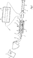
- FIG. 1 there is shown an installation for manufacturing a spheroidal graphite cast iron pipe according to a first embodiment of the invention, designated by the general reference 2.
- the installation 2 comprises a feed ladle 4, a pouring device 6, a pouring channel 8, an inoculation device 9, a rotating mold 10, a cooling device 12 and an extraction device 14 .
- Installation 2 is used to manufacture piping elements 15, such as pipes, by centrifugation.
- the pipe element 15 forms an object or a base body 16 of spheroidal graphite cast iron.
- the supply ladle 4 is a crucible made of refractory material containing liquid metal, such as cast iron.
- the pouring device 6 also called “basket”, has a volume corresponding to the quantity of liquid metal necessary to manufacture one or more base bodies 16.
- the pouring device 6 can be tilted in a position for pouring the liquid metal into the channel casting 8.
- the pouring channel 8 conducts the liquid metal from the pouring device 6 to the mold 10. It comprises an inlet 20 located close to the pouring device 6 and an outlet 22 extending into the mold 10.
- the pouring channel 8 is inclined relative to the horizontal so that the outlet 22 is located lower than the inlet 20, thereby allowing the molten iron to flow by gravity.
- the rotary mold 10, also called “shell”, has a shape with symmetry of revolution, in the present example generally cylindrical, of axis XX, inclined with respect to the horizontal so that it is parallel to the channel of casting 8.
- the mold 10 has an inner surface 24 of shape which is the negative surface of the base body 16, as well as a cylindrical outer surface 26.
- the inner surface 24 is provided with a controlled roughness called “peening”, making it possible to drive the liquid metal in rotation during its casting in the mold 10.
- the mold 10 comprises a spigot end 28, facing the entrance 20, and a socket end 30, which faces away from the entrance 20 and which is provided with a core (not shown).
- the spigot end 28 forms the spigot end of the base body 16, while the socket end 30 forms the socket end of the base body 16.
- the mold 10 can be rotated around the X-X axis. Furthermore, the mold 10 can be driven in translation along the X-X axis between a casting start position, in which the outlet 22 is opposite the interlocking end end 30, and a casting end position. , wherein outlet 22 faces spigot end 28.
- the cooling device 12 comprises a spraying means which is adapted to spray cooling liquid, for example water, onto the outer surface 26 of the mold 10.
- the extraction device 14 is adapted to extract axially from the mold 10 the basic body blank 16 obtained at the end of the casting of the liquid metal in the mold.
- the pouring 6, cooling 12 and extraction 14 devices, the supply ladle 4 and the pouring channel 8 are known per se and are not described in more detail.
- the mold 10 is for example entirely made of forged steel.
- the installation further comprises a heat treatment furnace 40.
- the manufacture of the object or of the basic body 16 according to the invention by means of the installation 2 is carried out as follows.
- the manufacturing process implemented is a process having the characteristics of the manufacturing process called “DeLavaud”.
- Liquid cast iron is introduced into the supply ladle 4.
- the liquid cast iron in the ladle 4 is such that the object or base body 16 obtained with the manufacturing method according to the invention has the chemical composition defined below , and in particular has the silicon content according to the invention.
- the establishment of the final silicon content of the object or of the base body 16 is made before the casting step in the mold 10, by additions of materials containing silicon, in particular FeSi alloys. These additions are made, for example, in the liquid cast iron bath of electric furnaces or in supply ladles.
- Any silicon intake resulting from spheroidization and/or inoculation treatments using silicon-based agents must be taken taken into account to determine the quantity of silicon to be added to the liquid metal to obtain an object or base body 16 having a silicon content in accordance with the invention.
- the establishment of the final silicon content of the object or of the base body 16, made before the casting step in the mold 10, is carried out by adding to the cast iron a silicon content equal to that of the object minus the content provided by inoculation and/or spheroidization.
- the increase in the silicon content of the spheroidal graphite cast iron according to the invention must not be obtained by increasing the quantity of silicon-based inoculating agent.
- the silicon content in the cast iron of the object provided by the inoculating agent is between 0.1% and 0.3%.
- Liquid cast iron corresponding to the quantity of cast iron required for the base body 16, is introduced into the pouring device 6 through the supply pocket 4.
- the mold 10 is rotated around the X-X axis and it is brought into its casting start position.
- the liquid iron is poured from the pouring device 6 into the pouring channel 8, flows along it and is poured into the mold 10 at the socket end 30.
- the mold 10 is brought towards its end of casting position while the liquid iron is gradually poured onto the interior surface 24 of the mold and that, before the liquid iron comes into contact with the interior surface 24, the device inoculation agent 9 deposits an inoculation agent, for example a powder based on FeSi, on the inner surface 24 of the mold 10.
- an inoculation agent for example a powder based on FeSi
- the inner surface 24 of the mold 10 is not covered with other materials and is in particular devoid of any temporary thermal insulation or temporary refractory material. as used during the casting process called "Wetspray” (see also below regarding the installation of the Figure 3 ).
- the mold 10 is cooled by the cooling device 12.
- the liquid cast iron in the mold 10 is pressed against the surface 24 by centrifugation, solidifies and forms a blank 161 of the base body 16.
- the blank 161 of the base body 16 is extracted from the mold 10 by the extraction device 14.
- the blank 161 of the base body 16 is subjected to a heat treatment, which will be described in more detail below and, at the end of the heat treatment, the base body 16 is obtained.
- composition of the spheroidal graphite cast iron used for the manufacturing process and therefore the composition of the base body 16 comprises, in% by weight, Carbon (C) at a content less than or equal to 3.65%, and Silicon (Si) at a content of between 3.3% inclusive and 3.7% inclusive.
- the rest of the spheroidal graphite cast iron is Iron (Fe), and other residual elements at levels lower than 0.01%, due to the cast iron production process or to inevitable impurities.
- the carbon equivalent C EQ is equal to 4.5%.
- the silicon (Si) content is preferably between 3.4% inclusive and 3.6% inclusive, and preferably between 3.5% inclusive and 3.6% inclusive, in particular in the case of the use of the process DeLavaud as is the case with the present embodiment.
- this “De Lavaud” manufacturing process comprises a step consisting of pouring liquid cast iron into the mold 10 and allowing the liquid cast iron to solidify, obtaining the draft of the cast iron object; then the blank of the cast iron object is subjected to a heat treatment.
- the molten iron is poured into the mold 10 whose shaped inner surface 24 is devoid of temporary thermal insulation or temporary refractory material deposited on the inner surface 24.
- the blank of the base body is at a temperature generally between 900° C. and 1000° C., and in particular equal to approximately 950° C.
- the blank of the base body is at a temperature generally between 550° C. and 650° C., in particular at a temperature of approximately 600° C., forming the starting temperature of the heat treatment in the oven.
- the blank of the cast iron object is heated for a period of between 2 and 10 minutes during a first heat treatment step ED1, until it reaches a temperature of graphitization greater than 800°C and in particular greater than 900°C, but less than 1000°C.
- This first step ED1 of temperature rise makes it possible to relax the internal stresses present in the cast iron.
- a second heat treatment step ED2 the blank of the cast iron object is maintained at the graphitization temperature which in the present case is equal to approximately 950° C.
- the second heat treatment step ED2 has a duration of between 5 minutes and 30 minutes, and in this case has a duration of 15 minutes.
- the cementite is dissolved and transformed into austenite and graphite.
- a third heat treatment step ED3 is implemented.
- the temperature is lowered, starting from the graphitization temperature, to a ferritization start temperature of between 880° C. and 750° C., in this case equal to approximately 800° C.
- the lowering of temperature during step ED3 is carried out over a period of time comprised between 4 and 7 minutes, preferably less than or equal to 6 minutes.
- a fourth heat treatment step ED4 which is a ferritization step
- the blank of the cast iron object is cooled slowly, that is to say at a cooling rate of less than 40° C./minute , preferably between 20°C/minute and 5°C/minute, within a temperature range between 700°C and 780°C.
- the austenite is transformed into ferrite and graphite.
- a fifth step ED5 the blank of the cast iron object is cooled from the temperature at the end of ferritization to a temperature below 100° C., and in particular to an ambient air temperature of 20° C.
- the spheroidal graphite cast iron thus obtained has a tensile strength Rm greater than 470 MPa and preferably a tensile strength Rm greater than 500 MPa and in particular greater than 530 MPa.
- spheroidal graphite cast iron having a silicon content as defined above and manufactured by the DeLavaud process described above meets this requirement.
- the spheroidal graphite cast iron according to the invention has an elongation at break greater than or equal to 7% and in particular greater than or equal to 8%, greater than or equal to 9% or greater than or equal to 10%.
- the spheroidal graphite cast iron of the object according to the invention has a resilience E greater than or equal to 9.49 Joules at ambient temperature (20° C.). This is obtained inter alia by the fact that the silicon rate does not exceed 3.7%.
- the resilience E is measured by the “Charpy sheep” shock method.
- the manufactured objects comply with the American standard AWWAC151.
- the resilience E measured according to the “Charpy” method is greater than or equal to 10 Joules or greater than or equal to 11 Joules.
- the spheroidal graphite cast iron of the object according to the invention has a Brinell hardness HB less than or equal to 230 HB.
- the pipe element 15 or the base body 16 has a nominal diameter DN and a wall thickness e.
- the nominal diameter DN is for example less than or equal to 600 mm or less than or equal to 1000 mm or less than or equal to 1600 mm.
- the pipe obtained with the installation of the figure 1 and having undergone the heat treatment as described above with reference to the Fig. 2 has a thickness of approximately 5.3 mm
- a pipe obtained with the classic DeLavaud process and whose cast iron has a silicon content of less than 2.9% has a thickness greater than 6.5 mm.
- the installation 2 and the method for manufacturing the pipe element according to this second embodiment differ from the installation and the method described above only in the following. Similar elements bear the same references.
- Installation 2 comprises a device (not shown) for applying a refractory material. This device is suitable for depositing a layer of a temporary refractory material 50 on the inner surface 24 of the mold 10.
- the temporary refractory material 50 is known per se and is for example a mixture of water, bentonite and silica-based refractory product.
- the layer of temporary refractory material 50 reduces the cooling rate of the cast iron cast in the mold 10.
- the temporary refractory material 50 is replaced by a temporary thermal insulation material.
- the manufacturing process using the installation 2 is a manufacturing process of the "Wetspray” type. This process is as follows.
- temporary refractory material 50 Prior to pouring liquid iron into mold 10, temporary refractory material 50 is disposed on interior surface 24 and forms a layer of temporary refractory material.
- the next step is to pour the liquid iron over the layer of temporary refractory material
- the blank of the base body 16 or the blank of the cast iron object contains no or very little cementite.
- Spheroidal graphite cast iron has an essentially ferritic matrix with a low pearlite content, in particular less than or equal to 10%, given that the Si content is greater than 3.2%.
- FIG 4 is represented the temperature/time diagram during the heat treatment of the blank of the base body 16 or more generally of a blank of the cast iron object manufactured according to the “Wetspray” process by the installation 2 according to the second mode of achievement shown on the picture 3 .
- the blank of the basic body 16 or of the cast iron object undergoes a heat treatment.
- the blank of the basic body or of the object is introduced into a furnace at an inlet temperature greater than 800°C and, in a first heat treatment step EW1, is cooled at a cooling rate of less than 40°C/minute down to an end-of-ferritization temperature below 740°C and preferably between 700°C and 740°C.
- This first step EW1 is a ferritization step during which the austenite is transformed into ferrite and into graphite.
- the blank of the base body or of the cast iron object is cooled from the temperature at the end of ferritization to a temperature below 100° C., and preferably between 20°C and 100°C excluded.
- This cooling takes place in air, that is to say at a rate of between 30° C./min and 70° C./min and preferably between 40° C./min and 60° C./min and in particular at about 50°C/min.
- the air temperature during this cooling is between 10°C and 40°C.
- a relaxation heat treatment intended to relax the internal stresses initially present in the cast iron. This consists first of all in heating the blank of the base body 16 or of the cast iron object from the aforementioned temperature located between 20° C. and 100° C. to a relaxation temperature of between 600° C. and 700° C. °C, then maintaining the blank of the basic body or of the cast iron object at this relaxation temperature for a period of between 10 minutes and 30 minutes.
- a fourth step EW4 the blank of the base body 16 or of the cast iron object is cooled down to ambient temperature (20° C.).
- the nominal diameter DN is for example greater than 600mm.
- Tests carried out show that, for an identical bursting pressure and in the case for example of a DN800 pipe, the pipe obtained with the installation of the picture 3 and which has undergone the heat treatment described above with reference to the Fig. 4 has a thickness of approximately 7.7 mm, whereas a pipe obtained with the conventional Wetspray process and whose cast iron has a silicon content of less than 2.9% has a thickness greater than or equal to 9.4 mm.
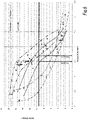
- the figure 6 shows the resilience E according to the "Charpy sheep” impact test and demonstrates that objects whose spheroidal graphite cast iron contains between 3.3% and 3.5% silicon and manufactured using the Wetspray process followed by a treatment thermal (“WS Treated”) as described above, have a resilience well in excess of 10 Joules, unlike spheroidal graphite cast iron obtained by the Wetspray process without subsequent heat treatment ("raw WS" on the figure 6 ) for which a resilience greater than 9.49 Joules is obtained only for silicon contents less than 3%.
- WS Treated treatment thermal
- the figure 7 shows that the objects obtained by the Wetspray process followed by the heat treatment ("WS Treated") according to the invention and having a silicon content of between 3.4 and 3.5% have an elongation A greater than 15% and in particular comprised between 18% and 22% approximately.
- the pipe member made by the above methods may be a tubular member other than a socket pipe, for example a cylindrical tube fitting.
- the composition of the spheroidal graphite cast iron according to the invention can also be used for the manufacture of a cast iron road element such as a manhole or a rainwater evacuation device, or for the manufacture foundry fittings.
- the method of manufacturing such objects consists in pouring liquid cast iron into a mold and inoculating it simultaneously. Then, after extraction from the mold and cooling to a temperature below 100° C., the blank of the cast iron object is subjected to a thermal relaxation treatment. This consists first of all in heating the blank of the object to a relaxation temperature greater than 400°C and preferably between 600°C and 700°C. Then, the blank of the cast iron object is maintained at this relaxation temperature for a period of between 10 minutes and 30 minutes approximately.
- the object blank is cooled to room temperature.
- the cast iron obtained at the end of this heat treatment makes it possible to reduce the weight of the road element or the foundry fitting compared to the known elements while maintaining a given mechanical resistance, or else, at the same weight, makes it possible to increase the mechanical performance of the road element or the foundry fitting.
- the impact strength of cast iron at room temperature (20° C.) is greater than or equal to 10J or greater than or equal to 11J. Resilience is notably measured by the “Charpy sheep” impact test.
- the spheroidal graphite cast iron object according to the invention therefore makes it possible to obtain pipe elements or roadway elements having low wall thicknesses for a given mechanical strength or improved mechanical performance at similar wall thicknesses. Manufacture and use, in particular transport and handling, are therefore economical.
Landscapes
- Chemical & Material Sciences (AREA)
- Engineering & Computer Science (AREA)
- Materials Engineering (AREA)
- Metallurgy (AREA)
- Organic Chemistry (AREA)
- Mechanical Engineering (AREA)
- Physics & Mathematics (AREA)
- Thermal Sciences (AREA)
- Crystallography & Structural Chemistry (AREA)
- Health & Medical Sciences (AREA)
- Child & Adolescent Psychology (AREA)
- Refinement Of Pig-Iron, Manufacture Of Cast Iron, And Steel Manufacture Other Than In Revolving Furnaces (AREA)
Applications Claiming Priority (3)
| Application Number | Priority Date | Filing Date | Title |
|---|---|---|---|
| FR1662781A FR3060607B1 (fr) | 2016-12-19 | 2016-12-19 | Objet en fonte a graphite spheroidal, element et procede de fabrication correspondants |
| PCT/EP2017/083378 WO2018114845A1 (fr) | 2016-12-19 | 2017-12-18 | Objet en fonte à graphite sphéroïdal, élément et procédé de fabrication correspondants |
| EP17823092.6A EP3555335B1 (de) | 2016-12-19 | 2017-12-18 | Verfahren zur herstellung eines gegenstand aus kugelgraphit-gusseisen |
Related Parent Applications (2)
| Application Number | Title | Priority Date | Filing Date |
|---|---|---|---|
| EP17823092.6A Division EP3555335B1 (de) | 2016-12-19 | 2017-12-18 | Verfahren zur herstellung eines gegenstand aus kugelgraphit-gusseisen |
| EP17823092.6A Division-Into EP3555335B1 (de) | 2016-12-19 | 2017-12-18 | Verfahren zur herstellung eines gegenstand aus kugelgraphit-gusseisen |
Publications (1)
| Publication Number | Publication Date |
|---|---|
| EP4050116A1 true EP4050116A1 (de) | 2022-08-31 |
Family
ID=58609511
Family Applications (2)
| Application Number | Title | Priority Date | Filing Date |
|---|---|---|---|
| EP22162181.6A Pending EP4050116A1 (de) | 2016-12-19 | 2017-12-18 | Verfahren zur herstellung eines gegenstands aus gusseisen mit kugelgraphit und entsprechendes element |
| EP17823092.6A Active EP3555335B1 (de) | 2016-12-19 | 2017-12-18 | Verfahren zur herstellung eines gegenstand aus kugelgraphit-gusseisen |
Family Applications After (1)
| Application Number | Title | Priority Date | Filing Date |
|---|---|---|---|
| EP17823092.6A Active EP3555335B1 (de) | 2016-12-19 | 2017-12-18 | Verfahren zur herstellung eines gegenstand aus kugelgraphit-gusseisen |
Country Status (5)
| Country | Link |
|---|---|
| EP (2) | EP4050116A1 (de) |
| CN (2) | CN114774767B (de) |
| ES (1) | ES2914548T3 (de) |
| FR (1) | FR3060607B1 (de) |
| WO (1) | WO2018114845A1 (de) |
Families Citing this family (8)
| Publication number | Priority date | Publication date | Assignee | Title |
|---|---|---|---|---|
| CA3095046A1 (en) | 2018-03-29 | 2019-10-03 | Oerlikon Metco (Us) Inc. | Reduced carbides ferrous alloys |
| EP3870727A1 (de) | 2018-10-26 | 2021-09-01 | Oerlikon Metco (US) Inc. | Korrosions- und verschleissbeständige legierungen auf nickelbasis |
| CN113631750A (zh) | 2019-03-28 | 2021-11-09 | 欧瑞康美科(美国)公司 | 用于涂布发动机气缸孔的热喷涂铁基合金 |
| CA3136967A1 (en) | 2019-05-03 | 2020-11-12 | Oerlikon Metco (Us) Inc. | Powder feedstock for wear resistant bulk welding configured to optimize manufacturability |
| KR102870036B1 (ko) | 2019-07-09 | 2025-10-13 | 오를리콘 메트코 (유에스) 아이엔씨. | 내마모성 및 내부식성을 위해 설계된 철 기반 합금 |
| FR3099716B1 (fr) * | 2019-08-08 | 2021-08-27 | Saint Gobain Pont A Mousson | Procédé de fabrication d’un élément tubulaire |
| RU2733940C1 (ru) * | 2020-03-02 | 2020-10-08 | Денис Александрович Габец | Чугун |
| FR3141698B1 (fr) | 2022-11-09 | 2024-11-08 | Saint Gobain Pam Batiment | Objet tubulaire en fonte à graphite lamellaire, élément de tuyauterie et procédé de fabrication correspondants |
Citations (6)
| Publication number | Priority date | Publication date | Assignee | Title |
|---|---|---|---|---|
| CA838011A (en) * | 1970-03-31 | United States Pipe And Foundry Company | Process for casting ductile iron | |
| FR2139866A1 (de) | 1971-06-03 | 1973-01-12 | Inst Odlewnictwa | |
| US3891432A (en) | 1973-01-24 | 1975-06-24 | Hitachi Ltd | High toughness spheroidal graphite cast iron and method for producing the same |
| JPH08269614A (ja) | 1995-03-31 | 1996-10-15 | Kubota Corp | ダクタイル鋳鉄管 |
| DE10101159A1 (de) | 2001-01-12 | 2002-07-25 | Siempelkamp Gmbh & Co | Gusswerkstoff mit ferritischem Gefüge und Kugelgraphit, insbesondere ferritisches Gusseisen |
| EP1566454A1 (de) * | 2004-02-10 | 2005-08-24 | Magna Drivetrain AG & Co KG | Verfahren zur Herstellung eines Werkstückes aus sphäroguss und nach diesem hergestelltes Werkstück |
Family Cites Families (10)
| Publication number | Priority date | Publication date | Assignee | Title |
|---|---|---|---|---|
| FR759342A (fr) * | 1932-08-20 | 1934-02-01 | Internat Delavaud Mfg Corp Ltd | Tuyaux en fonte et procédé pour les fabriquer |
| AT275763B (de) * | 1966-03-03 | 1969-11-10 | United States Pipe Foundry | Verfahren zum Gießen duktiler Gußstücke aus Eisen |
| US3415307A (en) * | 1966-03-03 | 1968-12-10 | United States Pipe Foundry | Process for casting ductile iron |
| FR2522291A1 (fr) * | 1982-03-01 | 1983-09-02 | Pont A Mousson | Tube centrifuge en fonte a graphite spheroidal et son procede de fabrication |
| US4475956A (en) * | 1983-01-24 | 1984-10-09 | Ford Motor Company | Method of making high strength ferritic ductile iron parts |
| US5082507A (en) * | 1990-10-26 | 1992-01-21 | Curry Gregory T | Austempered ductile iron gear and method of making it |
| CN101698921B (zh) * | 2009-09-07 | 2011-09-07 | 芜湖市金贸流体科技股份有限公司 | 一种耐磨球墨铸铁的制备方法 |
| KR101294671B1 (ko) * | 2011-11-14 | 2013-08-09 | 엘지전자 주식회사 | 구상흑연주철 및 그를 이용한 로터리 압축기용 베인의 제조방법 |
| CN104775067A (zh) * | 2015-04-01 | 2015-07-15 | 北京纵横机电技术开发公司 | 一种轨道车辆制动盘用合金球墨铸铁 |
| CN105506441B (zh) * | 2015-12-28 | 2017-09-29 | 中车齐齐哈尔车辆有限公司 | 球墨铸铁材料、包含其的组合物和承载鞍及球墨铸铁的制作方法 |
-
2016
- 2016-12-19 FR FR1662781A patent/FR3060607B1/fr active Active
-
2017
- 2017-12-18 EP EP22162181.6A patent/EP4050116A1/de active Pending
- 2017-12-18 CN CN202210254718.8A patent/CN114774767B/zh active Active
- 2017-12-18 WO PCT/EP2017/083378 patent/WO2018114845A1/fr not_active Ceased
- 2017-12-18 ES ES17823092T patent/ES2914548T3/es active Active
- 2017-12-18 CN CN201780078472.0A patent/CN110268082B/zh active Active
- 2017-12-18 EP EP17823092.6A patent/EP3555335B1/de active Active
Patent Citations (6)
| Publication number | Priority date | Publication date | Assignee | Title |
|---|---|---|---|---|
| CA838011A (en) * | 1970-03-31 | United States Pipe And Foundry Company | Process for casting ductile iron | |
| FR2139866A1 (de) | 1971-06-03 | 1973-01-12 | Inst Odlewnictwa | |
| US3891432A (en) | 1973-01-24 | 1975-06-24 | Hitachi Ltd | High toughness spheroidal graphite cast iron and method for producing the same |
| JPH08269614A (ja) | 1995-03-31 | 1996-10-15 | Kubota Corp | ダクタイル鋳鉄管 |
| DE10101159A1 (de) | 2001-01-12 | 2002-07-25 | Siempelkamp Gmbh & Co | Gusswerkstoff mit ferritischem Gefüge und Kugelgraphit, insbesondere ferritisches Gusseisen |
| EP1566454A1 (de) * | 2004-02-10 | 2005-08-24 | Magna Drivetrain AG & Co KG | Verfahren zur Herstellung eines Werkstückes aus sphäroguss und nach diesem hergestelltes Werkstück |
Also Published As
| Publication number | Publication date |
|---|---|
| FR3060607B1 (fr) | 2021-09-10 |
| CN114774767A (zh) | 2022-07-22 |
| CN110268082B (zh) | 2022-04-19 |
| EP3555335A1 (de) | 2019-10-23 |
| ES2914548T3 (es) | 2022-06-13 |
| WO2018114845A1 (fr) | 2018-06-28 |
| EP3555335B1 (de) | 2022-04-27 |
| CN110268082A (zh) | 2019-09-20 |
| FR3060607A1 (fr) | 2018-06-22 |
| CN114774767B (zh) | 2023-09-15 |
Similar Documents
| Publication | Publication Date | Title |
|---|---|---|
| EP3555335B1 (de) | Verfahren zur herstellung eines gegenstand aus kugelgraphit-gusseisen | |
| CA2203488C (fr) | Acier faiblement allie pour la fabrication de moules pour matieres plastiques | |
| BE896059A (fr) | Tube centrifuge en fonte a graphite spheroidal et son procede de fabrication | |
| EP1504132A1 (de) | Verfahren zur herstellung und formung von gussteilen aus kugelgraphit mit verbesserten mechanischen eigenschaften | |
| EP1063033B1 (de) | Verfahren zur Herstellung eines Werkstücks aus Metall, wie ein Teil eines Fahrzeugrads, und entsprechendes Rad | |
| EP1323837B1 (de) | Herstellungsverfahren von Stahlprodukt aus Kohlenstoffstahl insbesondere für Galvanisieren. | |
| CN106636879A (zh) | 一种球墨铸铁轧辊辊身及其制备方法 | |
| WO2024100133A1 (fr) | Objet tubulaire en fonte à graphite lamellaire, élément de tuyauterie et procédé de fabrication correspondants | |
| FR2682312A1 (fr) | Procede d'obtention de canaux de petite taille et de tres petite taille dans des articles coules a modele perdu. | |
| FR2486100A1 (fr) | Pieces massives en fonte a graphite spheroidal | |
| FR2526688A1 (fr) | Procede de fabrication d'une coquille tubulaire a section rectangulaire ou carree | |
| CN102191422A (zh) | 一种Fe2B块体/钢铁基复合材料制备方法 | |
| WO2019122635A1 (fr) | Procédé de traitement thermique d'une pièce en acier maraging | |
| CN114101619B (zh) | 一种球墨铸管的离心铸造工艺 | |
| HK40121022A (zh) | 片状石墨铸铁管状物体、相应的管道组件和相应的制造方法 | |
| EP1704948A1 (de) | Schleiffestes Rohr aus Metall und Verfahren zu seiner Herstellung | |
| CN101987348B (zh) | 压路机支架铸件的铸造方法 | |
| CH251451A (fr) | Procédé pour l'obtention d'objets métalliques moulés. | |
| FR3099716A1 (fr) | Procédé de fabrication d’un élément tubulaire | |
| BE690049A (de) | ||
| FR2868346A1 (fr) | Moule pour la coulee d'un metal liquide et procede correspondant | |
| BE735339A (de) | ||
| Zherebtsov et al. | Centrifugal electroslag casting of annular flange blanks | |
| FR2918908A1 (fr) | Procede de fabrication d'une piece en fonte bainitique | |
| BE428846A (de) |
Legal Events
| Date | Code | Title | Description |
|---|---|---|---|
| PUAI | Public reference made under article 153(3) epc to a published international application that has entered the european phase |
Free format text: ORIGINAL CODE: 0009012 |
|
| STAA | Information on the status of an ep patent application or granted ep patent |
Free format text: STATUS: THE APPLICATION HAS BEEN PUBLISHED |
|
| AC | Divisional application: reference to earlier application |
Ref document number: 3555335 Country of ref document: EP Kind code of ref document: P |
|
| AK | Designated contracting states |
Kind code of ref document: A1 Designated state(s): AL AT BE BG CH CY CZ DE DK EE ES FI FR GB GR HR HU IE IS IT LI LT LU LV MC MK MT NL NO PL PT RO RS SE SI SK SM TR |
|
| STAA | Information on the status of an ep patent application or granted ep patent |
Free format text: STATUS: REQUEST FOR EXAMINATION WAS MADE |
|
| 17P | Request for examination filed |
Effective date: 20230201 |
|
| RBV | Designated contracting states (corrected) |
Designated state(s): AL AT BE BG CH CY CZ DE DK EE ES FI FR GB GR HR HU IE IS IT LI LT LU LV MC MK MT NL NO PL PT RO RS SE SI SK SM TR |
|
| P01 | Opt-out of the competence of the unified patent court (upc) registered |
Effective date: 20230620 |