EP4051373B1 - Système pour induire des modifications épigénétiques dans les cellules et le tissu oculaires et orbitaires - Google Patents
Système pour induire des modifications épigénétiques dans les cellules et le tissu oculaires et orbitaires Download PDFInfo
- Publication number
- EP4051373B1 EP4051373B1 EP20881237.0A EP20881237A EP4051373B1 EP 4051373 B1 EP4051373 B1 EP 4051373B1 EP 20881237 A EP20881237 A EP 20881237A EP 4051373 B1 EP4051373 B1 EP 4051373B1
- Authority
- EP
- European Patent Office
- Prior art keywords
- eye
- wearable device
- coils
- internal
- external
- Prior art date
- Legal status (The legal status is an assumption and is not a legal conclusion. Google has not performed a legal analysis and makes no representation as to the accuracy of the status listed.)
- Active
Links
Images









Classifications
-
- A—HUMAN NECESSITIES
- A61—MEDICAL OR VETERINARY SCIENCE; HYGIENE
- A61N—ELECTROTHERAPY; MAGNETOTHERAPY; RADIATION THERAPY; ULTRASOUND THERAPY
- A61N1/00—Electrotherapy; Circuits therefor
- A61N1/02—Details
- A61N1/04—Electrodes
- A61N1/0404—Electrodes for external use
- A61N1/0472—Structure-related aspects
- A61N1/0476—Array electrodes (including any electrode arrangement with more than one electrode for at least one of the polarities)
-
- A—HUMAN NECESSITIES
- A61—MEDICAL OR VETERINARY SCIENCE; HYGIENE
- A61N—ELECTROTHERAPY; MAGNETOTHERAPY; RADIATION THERAPY; ULTRASOUND THERAPY
- A61N1/00—Electrotherapy; Circuits therefor
- A61N1/18—Applying electric currents by contact electrodes
- A61N1/32—Applying electric currents by contact electrodes alternating or intermittent currents
- A61N1/36—Applying electric currents by contact electrodes alternating or intermittent currents for stimulation
- A61N1/36014—External stimulators, e.g. with patch electrodes
-
- A—HUMAN NECESSITIES
- A61—MEDICAL OR VETERINARY SCIENCE; HYGIENE
- A61N—ELECTROTHERAPY; MAGNETOTHERAPY; RADIATION THERAPY; ULTRASOUND THERAPY
- A61N1/00—Electrotherapy; Circuits therefor
- A61N1/18—Applying electric currents by contact electrodes
- A61N1/32—Applying electric currents by contact electrodes alternating or intermittent currents
- A61N1/36—Applying electric currents by contact electrodes alternating or intermittent currents for stimulation
- A61N1/36046—Applying electric currents by contact electrodes alternating or intermittent currents for stimulation of the eye
-
- A—HUMAN NECESSITIES
- A61—MEDICAL OR VETERINARY SCIENCE; HYGIENE
- A61N—ELECTROTHERAPY; MAGNETOTHERAPY; RADIATION THERAPY; ULTRASOUND THERAPY
- A61N1/00—Electrotherapy; Circuits therefor
- A61N1/40—Applying electric fields by inductive or capacitive coupling ; Applying radio-frequency signals
-
- C—CHEMISTRY; METALLURGY
- C12—BIOCHEMISTRY; BEER; SPIRITS; WINE; VINEGAR; MICROBIOLOGY; ENZYMOLOGY; MUTATION OR GENETIC ENGINEERING
- C12Q—MEASURING OR TESTING PROCESSES INVOLVING ENZYMES, NUCLEIC ACIDS OR MICROORGANISMS; COMPOSITIONS OR TEST PAPERS THEREFOR; PROCESSES OF PREPARING SUCH COMPOSITIONS; CONDITION-RESPONSIVE CONTROL IN MICROBIOLOGICAL OR ENZYMOLOGICAL PROCESSES
- C12Q1/00—Measuring or testing processes involving enzymes, nucleic acids or microorganisms; Compositions therefor; Processes of preparing such compositions
- C12Q1/68—Measuring or testing processes involving enzymes, nucleic acids or microorganisms; Compositions therefor; Processes of preparing such compositions involving nucleic acids
- C12Q1/6869—Methods for sequencing
- C12Q1/6874—Methods for sequencing involving nucleic acid arrays, e.g. sequencing by hybridisation
-
- C—CHEMISTRY; METALLURGY
- C12—BIOCHEMISTRY; BEER; SPIRITS; WINE; VINEGAR; MICROBIOLOGY; ENZYMOLOGY; MUTATION OR GENETIC ENGINEERING
- C12Q—MEASURING OR TESTING PROCESSES INVOLVING ENZYMES, NUCLEIC ACIDS OR MICROORGANISMS; COMPOSITIONS OR TEST PAPERS THEREFOR; PROCESSES OF PREPARING SUCH COMPOSITIONS; CONDITION-RESPONSIVE CONTROL IN MICROBIOLOGICAL OR ENZYMOLOGICAL PROCESSES
- C12Q1/00—Measuring or testing processes involving enzymes, nucleic acids or microorganisms; Compositions therefor; Processes of preparing such compositions
- C12Q1/68—Measuring or testing processes involving enzymes, nucleic acids or microorganisms; Compositions therefor; Processes of preparing such compositions involving nucleic acids
- C12Q1/6876—Nucleic acid products used in the analysis of nucleic acids, e.g. primers or probes
- C12Q1/6883—Nucleic acid products used in the analysis of nucleic acids, e.g. primers or probes for diseases caused by alterations of genetic material
-
- G—PHYSICS
- G02—OPTICS
- G02C—SPECTACLES; SUNGLASSES OR GOGGLES INSOFAR AS THEY HAVE THE SAME FEATURES AS SPECTACLES; CONTACT LENSES
- G02C7/00—Optical parts
- G02C7/02—Lenses; Lens systems ; Methods of designing lenses
- G02C7/04—Contact lenses for the eyes
-
- A—HUMAN NECESSITIES
- A61—MEDICAL OR VETERINARY SCIENCE; HYGIENE
- A61N—ELECTROTHERAPY; MAGNETOTHERAPY; RADIATION THERAPY; ULTRASOUND THERAPY
- A61N1/00—Electrotherapy; Circuits therefor
- A61N1/18—Applying electric currents by contact electrodes
- A61N1/32—Applying electric currents by contact electrodes alternating or intermittent currents
- A61N1/36—Applying electric currents by contact electrodes alternating or intermittent currents for stimulation
- A61N1/372—Arrangements in connection with the implantation of stimulators
- A61N1/378—Electrical supply
- A61N1/3787—Electrical supply from an external energy source
-
- C—CHEMISTRY; METALLURGY
- C12—BIOCHEMISTRY; BEER; SPIRITS; WINE; VINEGAR; MICROBIOLOGY; ENZYMOLOGY; MUTATION OR GENETIC ENGINEERING
- C12Q—MEASURING OR TESTING PROCESSES INVOLVING ENZYMES, NUCLEIC ACIDS OR MICROORGANISMS; COMPOSITIONS OR TEST PAPERS THEREFOR; PROCESSES OF PREPARING SUCH COMPOSITIONS; CONDITION-RESPONSIVE CONTROL IN MICROBIOLOGICAL OR ENZYMOLOGICAL PROCESSES
- C12Q2600/00—Oligonucleotides characterized by their use
- C12Q2600/106—Pharmacogenomics, i.e. genetic variability in individual responses to drugs and drug metabolism
-
- C—CHEMISTRY; METALLURGY
- C12—BIOCHEMISTRY; BEER; SPIRITS; WINE; VINEGAR; MICROBIOLOGY; ENZYMOLOGY; MUTATION OR GENETIC ENGINEERING
- C12Q—MEASURING OR TESTING PROCESSES INVOLVING ENZYMES, NUCLEIC ACIDS OR MICROORGANISMS; COMPOSITIONS OR TEST PAPERS THEREFOR; PROCESSES OF PREPARING SUCH COMPOSITIONS; CONDITION-RESPONSIVE CONTROL IN MICROBIOLOGICAL OR ENZYMOLOGICAL PROCESSES
- C12Q2600/00—Oligonucleotides characterized by their use
- C12Q2600/154—Methylation markers
-
- G—PHYSICS
- G02—OPTICS
- G02C—SPECTACLES; SUNGLASSES OR GOGGLES INSOFAR AS THEY HAVE THE SAME FEATURES AS SPECTACLES; CONTACT LENSES
- G02C11/00—Non-optical adjuncts; Attachment thereof
- G02C11/10—Electronic devices other than hearing aids
Definitions
- This specification relates to systems and methods for inducing changes to an eye or adjacent areas.
- Retinal blindness such as Retinitis Pigmentosa (RP), Age-Related Macular Degeneration (AMD), and glaucoma (POAG) are multi-phase conditions characterized by unrelenting neuronal death (photoreceptor loss in RP and AMD and ganglion cell loss in POAG). Neuronal rewiring, reprogramming, and migration can manifest early in these conditions. A number of mechanisms have been identified as to why neuronal death occurs in these different retinal blinding disorders (e.g., genetic mutations in RP, lipid metabolism abnormalities and inflammation in AMD, and elevated intraocular pressure in POAG to name a few). Although treatments to ameliorate these conditions exist, for many afflicted, there is no cure. Thus, there is a need for improved treatment of these conditions.
- RP Retinitis Pigmentosa
- AMD Age-Related Macular Degeneration
- POAG glaucoma
- US-A1-2018/332409 discloses an eye-mounted hearing aid which stimulates a cornea using sound captured with a microphone.
- WO-A1-2019/028474 discloses systems and methods for wireless stimulation of biological tissue, in particular to therapy for glaucoma.
- US-A1-2016/106576 discloses controllers for dry eye treatment which comprise a patch affixed to the skin of the upper and/or lower eyelids to deliver heat.
- the system includes an external RF coil configured to transmit RF signals.
- the system also includes a wearable device configured to be removably disposed on the eye, the wearable device including a plurality of internal radiofrequency (RF) coils configured to receive the RF signals from the external RF coil and a plurality of stimulating electrodes configured to electromagnetically stimulate a portion of the eye or an area adjacent to the eye, causing changes to cells or tissue within the eye or adjacent to the eye.
- RF radiofrequency
- the method includes transmitting, by an external RF coil, RF signals.
- the method also includes receiving, by a plurality of internal radiofrequency (RF) coils of a wearable device removably disposed on the eye, the RF signals from the external RF coil.
- the method also includes stimulating, by a plurality of stimulating electrodes, a portion of the eye or an area adjacent to the eye, causing the changes to the cells or tissue within or adjacent to the eye.
- RF radiofrequency
- a wearable device having an outer surface and an inner surface, the inner surface configured to removably contact an eye of a user.
- the wearable device also includes a plurality of stimulating electrodes configured to electromagnetically stimulate a portion of the eye or an area adjacent to the eye, causing changes to cells or tissue within or adjacent to the eye.
- neuroepigenetics pertaining to the study of epigenetics in post-mitotic neurons
- CNS Central Nervous System
- Electrical stimulation of the retina or of cultured Muller cells may lead to transcriptomic changes that were indicative of neuroprotective changes, including downregulation of proapoptotic genes such as Bax and upregulation of prosurvival genes such as brain-derived neurotrophic factor (bdnf).
- the systems and methods described herein are based on neuroepigenetic and chromatin remodeling of the retina induced through controlled electrical stimulation being a key molecular determinant of neuroprotection. This is pivotal for the treatment of retinal degenerative diseases, as shown in FIG. 1 .
- the systems and methods described herein use a non-invasive wearable device to control electrical stimulation to induce epigenetic changes in the eye, thereby slowing the progression of neural degeneration.
- the wearable device is a soft, doughnut shaped, contact lens with coils and electrodes worn at night time, which may be referred to herein as an "e-lens.”
- Transcorneal electrical stimulation may reduce the rate of death of photoreceptors as well as delay the progression of retinal degenerative diseases.
- Other invasive methods may have a variety of effects on the retina, ranging from promotion of the survival of the axotomized retinal ganglion cells to rescue of photoreceptors.
- FIG. 2A illustrates a system 200 for transcorneal electrical stimulation (TES).
- the system 200 includes a wearable device 202 configured to be removably disposed on an eye 203. That is, the wearable device 202 may be placed onto and removed from the eye 203.
- the wearable device 202 may be similar in material, shape, and dimensions, to a contact lens.
- the wearable device 202 has an aperture 207 in the center, which allows for corneal oxygenation.
- the aperture 207 may also provide an opening for the cornea, iris, and pupil (among other portions of the eye 203) to enable the user to see through the wearable device 202.
- the wearable device 202 includes a plurality of internal radiofrequency (RF) coils 204 connected to a plurality of stimulating electrodes 206. Also connected to the internal RF coils 204 and the stimulating electrodes may be one or more capacitors and diodes 210.
- RF radiofrequency
- the stimulating electrodes 206 do not cover or damage the cornea and are designed so as to maximize electric current flow in the retina as determined through computational simulations described herein.
- the internal RF coils 204 are configured to inductively receive power from external RF coils 208. That is, the external RF coils 208 send RF signals to the internal RF coils 204, and the internal RF coils 204 receive the RF signals. The power received from the external RF coils 208 is provided to the stimulating electrodes for stimulating various portions of the eye 203.
- the stimulating electrodes 206 may have any shape as may be appropriate for the treatment of the eye 203.
- FIG. 2B illustrates the wearable device 202 without the internal RF coils 204.
- the wearable device 202 has an outer surface 212 and an inner surface 214.
- the inner surface 214 is configured to contact the eye 203 of the user.
- the outer surface 212 is opposite the inner surface 214 and the outer surface 212 faces the external RF coils 208.
- the wearable device 202 may also include a plurality of grooves 216 for receiving and housing the internal RF coils 204.
- the plurality of grooves 216 may be located on the outer surface 212 or the inner surface 214. In some embodiments, the plurality of grooves 216 are channels formed within the wearable device 202 and the internal RF coils 204 are embedded in the wearable device 202 between the outer surface 212 and the inner surface 214.
- the stimulating electrodes 206 and the capacitors and diodes 210 may be located on the outer surface 212 or the inner surface 214 of the wearable device 202, or in some embodiments, may be embedded within the material of the wearable device 202 such that they are between the outer surface 212 and the inner surface 214.
- the stimulating electrodes 206 being effectively on the eye 203 helps to reduce impedance, as compared to a system where the stimulating electrodes are located outside of the eye and the eyelid is located between the eye and the stimulating electrodes. In systems where the eyelid separates the eye and the stimulating electrodes, the eyelid and other parts of the user may introduce impedance to the system, reducing efficiency and efficacy.
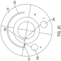
- FIG. 2C is an example embodiment of locations and shapes of the stimulating electrodes 206 for focusing the stimulation at the location 218, and other embodiments for focusing the stimulation at other locations is possible.
- Such an approach can be used both early in disease such as RP, AMD, and POAG or as an adjunct late in retinal diseases in combination with drugs, device or surgery.
- the wearable device 202 could be worn overnight as it does not completely cover the cornea and hence does not interfere with corneal oxygenation. Overnight use would also make it easy to comply with as it would not interfere with daytime activities such as reading.
- the systems and methods described herein could also be used for other neurodegenerative diseases and neural injuries such as stroke or closed head injury. Benefits of the systems and methods could also be realized to ailments where it is known that epigenetic alterations are involved in their progression, such as cancer. For example, early stage glioblastoma (type of brain cancer) could be slowed down in progression but also the neurons around the cancer could be protected from cell death.
- cancer for example, early stage glioblastoma (type of brain cancer) could be slowed down in progression but also the neurons around the cancer could be protected from cell death.
- FIG. 3 illustrates the eye 203 and various areas of the eye that may be stimulated using the system 200.
- the retina 302 and the optic nerve 304 may be stimulated to treat retinal blindness, such as Retinitis Pigmentosa (RP), Age-Related Macular Degeneration (AMD), and glaucoma (POAG).
- the ciliary body 306 may be stimulated to treat or delay presbyopia. Portions of the eye or within the eye may be treated, and areas adjacent to the eye may also be treated.
- the lacrimal gland (not pictured) which makes tears, may also be stimulated as a treatment for dry eye.
- the corneal epithelium may also be treated.
- FIG. 4 illustrates example devices that can house the external RF coils 208.
- the external RF coils 208 may be housed in a mask 402 or glasses 404, for example.
- the system 200 may be used while the user is sleeping.
- a mask 402 with the RF coils 208 at a location corresponding to the eyes of the user may be used.
- glasses 404 may be used when the user is not sleeping, with the RF coils 208 at a location corresponding to the eyes of the user.
- the RF coils 208 may be within sufficient distance to the internal RF coils 204 to inductively provide power to the stimulating electrodes 206 when the mask 402 or glasses 404 are worn by the user.
- the devices that house the external RF coils 208 may contain a power source or may be connected to a power source to provide current to the external RF coils 208.
- FIG. 5A illustrates a system 500 having a wearable device 202 and external RF coils 208, as described herein.
- the wearable device 202 may have stimulating electrodes 206 connected to internal RF coils 204, also as described herein.
- the internal RF coils 204 may be inductively powered by the external RF coils 208.
- the internal RF coils 204 may power the stimulating electrodes 206 to stimulate portions of the eye, as described herein.
- FIG. 5B illustrates a system 520 that does not include inductive power transfer.
- the wearable device 202 includes the stimulating electrodes 206 and also includes an internal power source 502 configured to provide power to the stimulating electrodes 206.
- the internal power source 502 may be disposed on or within the wearable device 202.
- the internal power source 502 is a battery.
- the internal power source 502 is a device that generates electricity based on movement, such as a triboelectric generator. The electricity may be generated based on movement of the user, including movement of the eye. In this way, the system 520 is a self-contained treatment apparatus.
- the internal power source 502 may also include a power storage device, such as a battery.
- FIG. 5C illustrates a system 540 that also does not include inductive power transfer.
- the wearable device 202 includes the stimulating electrodes 206 that are connected to an external power source 504 configured to provide power to the stimulating electrodes 206.
- the external power source 504 is a battery.
- the external power source 504 is a device that generates electricity based on solar energy, such as a solar panel.
- the external power source 504 is a device that generates electricity based on movement, such as a triboelectric generator. The electricity may be generated based on movement of the user.
- the external power source 504 may be located on a device to be worn by the user, such as glasses or a hat or an adhesive patch to be placed on the skin of the user.
- the external power source 504 may also include a power storage device, such as a battery.
- an external mobile computing device such as a smartphone, a laptop, or a tablet, may control the wearable device 202, including providing instructions for controlling the stimulating electrodes, for example.
- the external mobile computing device may be communicatively coupled to the wearable device 202 using a wired connection or a wireless connection, and communication may be performed using appropriate hardware, such as transceivers, and corresponding communications protocols, such as Bluetooth.
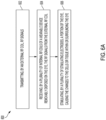
- FIG. 6A illustrates a process 600 for causing changes to cells or tissue within or adjacent to an eye, which is described herein for illustrative purposes.
- An external radiofrequency (RF) coil e.g., external RF coils 208 transmits RF signals (step 602).
- a plurality of internal RF coils e.g., internal RF coils 204) receive the RF signals from the external RF coil (step 604).
- the internal RF coils are located on a wearable device (e.g., wearable device 202) that is removably disposed on an eye (e.g., eye 203).
- a plurality of stimulating electrodes stimulate a portion of the eye or an area of the patient/user adjacent to the eye, causing changes to the cells or tissue within or adjacent to the eye (step 606).
- stimulating electrodes 206 stimulate a portion of the eye or an area of the patient/user adjacent to the eye, causing changes to the cells or tissue within or adjacent to the eye (step 606).
- “cells or tissue adjacent to the eye” refers to any cells or tissue near, around, in the vicinity of, adjacent to, or surrounding the eye and "area of the patient or user adjacent to the eye” refers to any area of the body near, around, in the vicinity of, adjacent to, or surrounding the eye.
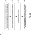
- FIG. 6B illustrates a process 620 for verifying inducement of epigenetic changes by the systems described herein.
- the process 620 is described herein for illustrative purposes.
- one or more steps of the process 600 may be performed using a computing device having a computer processor and a non-transitory memory storing instructions to be executed by the computer processor.
- DMRs Differentially methylated regions
- the DMRs are validated using targeted bisulfate amplicon sequencing (step 624).
- the transcriptional changes are confirmed (step 626) and the DMRs are used as biomarkers of response to electrical stimulation and for monitoring duration of effect at a molecular level (step 628).
- the half-wave rectifier (HWR) solution does not provide a charge-balanced waveform. That is, the HWR is always monophasic with each cycle. Use of charge-balanced waveforms are important to avoid imbalanced charge being transmitted through the eye tissue. Charge-balances waveforms are biphasic with each cycle.
- the circuit 700 shown in FIG. 7A may be used in the systems and methods described herein.
- the circuit 700 includes a transmitter portion 702 and a receiver portion 704.
- the transmitter portion 702 may be used with the external RF coils 206 and the receiver portion 704 may be used with the internal RF coils 204.
- the circuit 700 is capable of delivering a charge-balanced and higher output voltage than a half-wave rectifier system for a given load and input conditions.
- the output voltage across the load resistor is a difference of voltage across nodes OUT p and OUT n .
- the circuit 700 assumes that the load of the current stimulating system is in kQ.
- one end of the load resistor is grounded, and the other end of the load resistor swings to either positive or negative value depending on the diode polarity.
- the load resistor's ground side is also connected to one end of the receiver coil to complete the circuit.
- the circuit 700 achieves higher voltage across the load resistor (R load ) by generating negative voltage without losing efficiency.
- the voltage across the load is given by V(a)-V(b).
- the receiver inductor L Receiver , D 1 , C s1 and C L1 form an HWR charge-balanced positive rectifier circuit at the node OUT p .
- receiver inductor L Receiver , D 2 , C s2 and C L2 form an HWR charge-balanced negative rectifier circuit at the node OUT n .
- a series capacitor in series with a single HWR circuit will reduce the output voltage.
- the effective output voltage increases when the load voltage is tapped differentially.
- the load resistor is connected such that it acts as an RF blocker.
- FIGS. 7B-7E illustrate performance of the circuit 700.
- the waveforms may be tuned by adjusting components, such as capacitors.
- the transmitted input signal may be a pulsed RF signal.
- Using a Type 3 RF signal not only leads to higher induced voltage, but also leads to asymmetric induction of the secondary coil open circuit voltage. This asymmetry in the induced voltage increases the load output voltage.
- the peak to peak voltages of all the signals may be the same (e.g., 5V).
- the asymmetry induced by the Type 3 signal can be attributed to differentiation property of the induction process.
- the circuit 700 may be further modified by adding a diode D3 as shown in FIG. 7J to increase the anodic voltage without affecting the cathodic voltage.
- the effect of the modified circuit on the load voltage and charge is shown in FIGS. 7K and 7L .
- Circuit A referenced in FIGS. 7K and 7L is the circuit of FIG. 7J without diode D3
- Circuit B referenced in FIGS. 7K and 7L is the circuit of FIG. 7J .
- This modification also helps to control the anodic charge decay rate independently from the cathodic charge decay rate. This is useful when tuning the shape of the stimulating waveform without affecting the efficiency of the system. It is not possible to independently tune the anodic decay rates is in existing half wave rectifiers and voltage doubling circuits, which are monophasic.
- the output voltage for a Type 3 RF voltage input, coil relative polarity shown in the circuit 700 can be increased by increasing the conduction of the diode D 2 .
- D 2 For example, replacing a 1N5819 diode with MBR745 diode increases the output voltage.
- a parallel diode and capacitor to D 2 and C s2 pair can increase the output voltage.
- the output voltage and the charge balance waveforms of an HWR and the circuit 700 are shown below.
- the two systems are compared under similar input waveform, transmitter - receiver coils and loading conditions.
- the details of the simulation parameters are given in the table below.
- the output voltage of the proposed circuit is higher than the HWR. Also, unlike the HWR, the circuit 700 achieves charge balance.
- HWR Circuit 700 Diodes used 1N5819 1N5819 (MBR745) Load 2 k ⁇ 2 k ⁇ Input waveform same same Tx coil Inductance 1 uH, 0.5 ⁇ 1 uH, 0.5 ⁇ , Rx coil Inductance 10 uH, 1 ⁇ 10 uH, 1 ⁇ Capacitors 0.2 uF ( tried higher values ) 0.2 uF and 5 uF
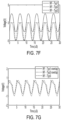
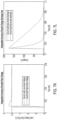
- FIGS. 7H and 7I A comparison of output voltage and charge between the proposed system described herein and HWR are shown in FIGS. 7H and 7I .
- the circuit 800 shown in FIG. 8A may be used in the systems and methods described herein.
- the circuit 800 includes a transmitter portion 802 and a receiver portion 804.
- the transmitter portion 802 may be used with the external RF coils 206 and the receiver portion 804 may be used with the internal RF coils 204.
- the circuit 800 is charge-balanced.
- the circuit 700 results in different waveforms based on load resistance, which is the resistance from the eye.
- load resistance which is the resistance from the eye.
- different eyes and different states of the eyes may result in different load resistances, and the shape of the waveform from the receiver portion 704 may vary based on the eye.
- the circuit 800 is load independent. That is, regardless of the load resistance from the eye of the user, the same waveform shape is achieved from the receiver portion 804.
- FIG. 8B illustrates the input voltage waveform.
- FIGS. 8C and 8D illustrate the same waveform being achieved at the receiver portion 804 regardless of the load resistance, demonstrating the ability of the circuit 800 to be load independent.
- FIG. 9A shows a human head model including the designed ground system and stimulating electrodes.
- the focalized voltage distributions into the eyes are depicted in FIG. 9B .
- the initial simulation findings demonstrate the potential for select stimulation of the eye and further enhancing the voltage gradient along the retina. This shows the greatest efficacy for stimulation of the retina as well as avoiding induced neural activities in other parts of the human body using the designed ground geometry.
- the wireless lens is to be worn for a limited period daily - primarily at night - with the transmitting external coil integrated on a wearable mask or similar device.
- Chromatin is a compact and highly organized hierarchical assembly of DNA and proteins that is intricately folded into three dimensions, forming different levels of organization in the nucleus. Chromatin packing density has a non-monotonic effect on the probability of gene expression, enhancing the rates of expression at chromatin packing densities below ⁇ 35% of chromatin volume concentration and suppressing expression at higher chromatin densities due to the competing effects of two consequences of molecular crowding, increased binding of transcriptional complexes and suppressed diffusion. Recent evidence indicates that chromatin packing scaling modulates both transcriptional diversity (the dynamic range of gene expression) and intercellular variation in gene transcription.
- Chromatin packing regulates cells' transcriptional access to their genomic space and is expected to have implications on a wide range of cellular processes (e.g., cell differentiation, plasticity, tissue regeneration, and many diseases including neurodegenerative diseases).
- DNA methylation can also impact proximal chromatin structure and regulate gene expression, playing critical roles in biological processes including embryonic development, Xchromosome inactivation, genomic imprinting, and chromosome stability.
- determining the methylation status at a single base resolution in the genome is an important step in elucidating its role in regulating many cellular processes and its disruption in disease states.
- WGBS whole genome bisulfite sequencing
- RCS retinal degeneration
- genomic DNA is sheared, end-repaired, 3'-adenylated, and ligated to adaptors.
- the adapter-ligated DNA is then treated with sodium bisulfite and PCR amplified to reach the yield needed for sequencing. Paired end sequencing of bisulfite-converted libraries was performed on the NovaSeq 6000 system.
- WGBS reads were aligned to the Rattus norvegicus RNOR6 genome assembly using open source Bismark Bisulfite Read Mapper with the Bowtie2 alignment algorithm.
- Targeted bisulfite amplicon sequencing was performed on 18 of these DMRs to confirm DNA methylation changes in response to TES stimulation in an independent cohort of RCS rat retinas.
- 9 showed good concordance between the whole genome and targeted bisulfite sequencing runs, with a correlation of 0.725 ( FIG. 11 ), validating the method of identifying consistent DMRs after TES treatment.
- qRTPCR quantitative reverse transcription polymerase chain reaction
- Pdgfa is not only known to be stimulated by electrical stimulations, but also known to attract astrocytes, and promote cell survival.
- Slco5a1 is a gene with known functions in rod cell function.
- the last group of 8 genes were downregulated compared to control but reduced expression was delayed and not evident until day 6 post TES. These included the downregulation of genes known to promote angiogenesis and neovascularization, such as Fgf8 and Fech ( FIG. 12 ). Aberrant ocular neovascularization driven by angiogenic factors has been shown to be a cause of several blinding eye diseases27, and inhibition of these factors, including Fech28, are currently being explored as potential therapeutics. In addition, proapoptotic genes such as Rassf129 ( FIG. 11 ) were also found to be downregulated.
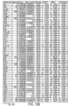
- FIGS. 13A-13B illustrate differentially methylated regions (DMRs) identified as being most significantly altered after electrical stimulation, and these DMRs could serve as putative biomarkers of response.
- the list in FIGS. 13A-13B is not an exclusive list.
Landscapes
- Health & Medical Sciences (AREA)
- Life Sciences & Earth Sciences (AREA)
- Engineering & Computer Science (AREA)
- General Health & Medical Sciences (AREA)
- Chemical & Material Sciences (AREA)
- Veterinary Medicine (AREA)
- Public Health (AREA)
- Animal Behavior & Ethology (AREA)
- Radiology & Medical Imaging (AREA)
- Nuclear Medicine, Radiotherapy & Molecular Imaging (AREA)
- Biomedical Technology (AREA)
- Proteomics, Peptides & Aminoacids (AREA)
- Organic Chemistry (AREA)
- Ophthalmology & Optometry (AREA)
- Physics & Mathematics (AREA)
- Zoology (AREA)
- Wood Science & Technology (AREA)
- Genetics & Genomics (AREA)
- Analytical Chemistry (AREA)
- Biophysics (AREA)
- Microbiology (AREA)
- Molecular Biology (AREA)
- Immunology (AREA)
- Bioinformatics & Cheminformatics (AREA)
- Biotechnology (AREA)
- General Engineering & Computer Science (AREA)
- Biochemistry (AREA)
- General Physics & Mathematics (AREA)
- Optics & Photonics (AREA)
- Heart & Thoracic Surgery (AREA)
- Pathology (AREA)
- Electrotherapy Devices (AREA)
Claims (12)
- Dispositif portable (202) conçu pour une stimulation électrique transcornéenne, comprenant :un matériau formé en forme de lentille de contact et configuré pour être placé de manière amovible sur un œil (203) d'un utilisateur, le matériau ayant une surface extérieure (212) et une surface intérieure (214), la surface intérieure étant configurée pour entrer en contact de manière mobile avec l'œil de l'utilisateur, le matériau comprenant une ouverture (207) située à un centre du matériau ; etune pluralité d'électrodes de stimulation (206) situées sur ou à l'intérieur du matériau et comprenant une électrode de masse (206C), une électrode négative (206A) et une électrode positive (206B), la pluralité d'électrodes de stimulation étant configurée pour stimuler électromagnétiquement une partie de l'œil ou une zone adjacente à l'œil.
- Dispositif portable (202) selon la revendication 1, comprenant en outre une pluralité de bobines radiofréquence RF internes (204) configurées pour recevoir des signaux RF provenant d'une bobine RF externe (208).
- Dispositif portable (202) selon la revendication 2, dans lequel la pluralité de bobines RF internes (204) est située à l'intérieur de gorges (216) sur la surface intérieure (214).
- Dispositif portable (202) selon la revendication 1, dans lequel la pluralité d'électrodes de stimulation (206) est alimentée par une batterie.
- Dispositif portable (202) selon la revendication 1, comprenant en outre un générateur triboélectrique, dans lequel la pluralité d'électrodes de stimulation (206) est en outre configurée pour être alimentée par le générateur triboélectrique.
- Dispositif portable (202) selon la revendication 2, comprenant en outre un ou plusieurs condensateurs connectés à la pluralité de bobines RF internes (204).
- Dispositif portable (202) selon la revendication 2, dans lequel les bobines RF internes (204) sont constituées de métaux ou d'autres matériaux conducteurs.
- Système (200) comprenant :un dispositif portable (202) selon l'une quelconque des revendications précédentes ; etune bobine RF externe (208) configurée pour transmettre des signaux RF.
- Système (200) selon la revendication 8, dans lequel une forme d'onde équilibrée en charge est utilisée pour stimuler la partie de l'œil (203) ou la zone adjacente à l'œil.
- Système (200) selon la revendication 8, dans lequel la bobine RF externe (208) est intégrée dans un masque ou une monture de lunettes configuré(e) pour être porté(e) par l'utilisateur.
- Système (200) selon la revendication 8, dans lequel la partie de l'œil (203) est constituée d'une rétine et d'un nerf optique, ou d'un corps ciliaire.
- Procédé de fonctionnement d'un dispositif portable (202) comportant un matériau formé en forme de lentille de contact et comprenant une ouverture (207) située dans un centre du matériau, le matériau étant configuré pour être placé de manière amovible sur un œil (203), le procédé comprenant :la transmission, par une bobine radiofréquence RF externe (208), de signaux RF ;la réception, par une pluralité de bobines RF internes (204) situées sur ou à l'intérieur du matériau du dispositif portable, des signaux RF provenant de la bobine RF externe ; etla réception, par une pluralité d'électrodes de stimulation (206) situées sur ou à l'intérieur du matériau du dispositif portable, des signaux RF provenant de la pluralité de bobines RF internes, la pluralité d'électrodes de stimulation comprenant une électrode de terre (206C), une électrode négative (206A) et une électrode positive (206B) .
Applications Claiming Priority (2)
| Application Number | Priority Date | Filing Date | Title |
|---|---|---|---|
| US201962927038P | 2019-10-28 | 2019-10-28 | |
| PCT/US2020/057680 WO2021086924A1 (fr) | 2019-10-28 | 2020-10-28 | Système et procédé pour induire des modifications épigénétiques dans les cellules et le tissu oculaires et orbitaires |
Publications (3)
| Publication Number | Publication Date |
|---|---|
| EP4051373A1 EP4051373A1 (fr) | 2022-09-07 |
| EP4051373A4 EP4051373A4 (fr) | 2023-11-15 |
| EP4051373B1 true EP4051373B1 (fr) | 2025-01-15 |
Family
ID=75714558
Family Applications (1)
| Application Number | Title | Priority Date | Filing Date |
|---|---|---|---|
| EP20881237.0A Active EP4051373B1 (fr) | 2019-10-28 | 2020-10-28 | Système pour induire des modifications épigénétiques dans les cellules et le tissu oculaires et orbitaires |
Country Status (5)
| Country | Link |
|---|---|
| US (2) | US12403311B2 (fr) |
| EP (1) | EP4051373B1 (fr) |
| CN (1) | CN114616025B (fr) |
| ES (1) | ES3019564T3 (fr) |
| WO (1) | WO2021086924A1 (fr) |
Families Citing this family (4)
| Publication number | Priority date | Publication date | Assignee | Title |
|---|---|---|---|---|
| USD1061894S1 (en) * | 2020-10-09 | 2025-02-11 | I-Lumen Scientific, Inc. | Medical device |
| US12472376B2 (en) | 2022-02-06 | 2025-11-18 | Demaod Ltd | Devices and methods for stimulating tear secretion |
| CN115006725A (zh) * | 2022-04-24 | 2022-09-06 | 清华大学 | 接触镜式无线经角膜电刺激仪以及实现方法 |
| CN115501478B (zh) * | 2022-09-19 | 2025-09-09 | 电子科技大学 | 一种用于角膜损伤修复的柔性压电角膜接触镜 |
Family Cites Families (37)
| Publication number | Priority date | Publication date | Assignee | Title |
|---|---|---|---|---|
| US4628933A (en) * | 1985-07-23 | 1986-12-16 | Michelson Robin P | Method and apparatus for visual prosthesis |
| US6544193B2 (en) * | 1996-09-04 | 2003-04-08 | Marcio Marc Abreu | Noninvasive measurement of chemical substances |
| US6458157B1 (en) * | 1997-08-04 | 2002-10-01 | Suaning Gregg Joergen | Retinal stimulator |
| US5935155A (en) * | 1998-03-13 | 1999-08-10 | John Hopkins University, School Of Medicine | Visual prosthesis and method of using same |
| US6197057B1 (en) * | 1998-10-27 | 2001-03-06 | Gholam A. Peyman | Lens conversion system for teledioptic or difractive configurations |
| DE60042155D1 (de) | 1999-03-24 | 2009-06-18 | Second Sight Medical Prod Inc | Retinale farbprothese zur wiederherstellung des farbsehens |
| US7103416B2 (en) * | 2001-01-16 | 2006-09-05 | Second Sight Medical Products, Inc. | Visual prosthesis including enhanced receiving and stimulating portion |
| US20050182489A1 (en) * | 2001-04-27 | 2005-08-18 | Peyman Gholam A. | Intraocular lens adapted for adjustment via laser after implantation |
| US8112157B2 (en) | 2005-05-27 | 2012-02-07 | California Institute Of Technology | Magnetic material-containing microfabricated devices for wireless data and power transfer |
| DE102005032989A1 (de) * | 2005-07-14 | 2007-01-25 | Imi Intelligent Medical Implants Ag | Extraokulares Epiretinal-Implantat |
| US20070244523A1 (en) * | 2006-04-13 | 2007-10-18 | Case Western Reserve University | System and method for selective retinal stimulation |
| US10529003B2 (en) * | 2008-04-07 | 2020-01-07 | Mohammad A. Mazed | Optical biomodule for detection of diseases at an early onset |
| US20080183242A1 (en) * | 2007-01-29 | 2008-07-31 | Nidek Co., Ltd. | Electrical stimulation method for vision improvement |
| ES2330405B1 (es) | 2008-06-06 | 2010-09-21 | Consejo Superior De Investigaciones Cientificas (Csic) (45%) | Lente de contacto sensora, sistema para la monitorizacion no invasiva de la presion intraocular y metodo para poner su medida. |
| CN101791259A (zh) * | 2010-01-07 | 2010-08-04 | 北京大学深圳研究生院 | 一种高密度微电极阵列的外层型人造视网膜前端系统设计 |
| CA2817589A1 (fr) * | 2010-11-16 | 2012-05-24 | The Board Of Trustees Of The Leland Stanford Junior University | Systemes et procedes pour traiter la secheresse oculaire |
| IT1403793B1 (it) * | 2010-12-30 | 2013-10-31 | St Microelectronics Srl | Protesi retinica |
| US9669213B2 (en) * | 2011-01-24 | 2017-06-06 | David Tsai | Stimulation method for maintaining the responsiveness of electrically excitable cells to repeated electrical stimulation |
| US10973680B2 (en) * | 2012-01-04 | 2021-04-13 | Sight Sciences, Inc. | Controller for dry eye treatment systems |
| WO2014031878A1 (fr) * | 2012-08-22 | 2014-02-27 | California Institute Of Technology | Système de transfert d'énergie sans fil à trois bobines pour implants oculaires |
| US9884180B1 (en) * | 2012-09-26 | 2018-02-06 | Verily Life Sciences Llc | Power transducer for a retinal implant using a contact lens |
| CA2956176A1 (fr) | 2014-07-25 | 2016-01-28 | Oculeve, Inc. | Stimulation pulsee pour traiter l'il sec |
| AU2015335772B2 (en) * | 2014-10-22 | 2020-07-09 | Oculeve, Inc. | Contact lens for increasing tear production |
| KR102248847B1 (ko) * | 2015-06-01 | 2021-05-06 | 삼성전자주식회사 | 에너지 수확부를 구비한 콘택트 렌즈 |
| WO2017048731A1 (fr) | 2015-09-15 | 2017-03-23 | Amerivision International, Inc. | Appareil et procédé pour thérapie de stimulation oculaire par microcourants |
| ITUB20154761A1 (it) * | 2015-10-29 | 2017-04-29 | Resono Ophthalmic S R L | Sistema di elettrodo e relativo dispositivo per il trattamento di patologie dell?occhio, in particolare dell?occhio secco |
| US10117740B1 (en) * | 2016-01-30 | 2018-11-06 | Verily Life Sciences Llc | Contact lens-based methods to deliver power to intraocular devices |
| WO2017167670A1 (fr) * | 2016-03-31 | 2017-10-05 | Koninklijke Philips N.V. | Lentille de contact, système et procédé de mesure d'une caractéristique physiologique d'un œil d'un sujet |
| US11191961B2 (en) * | 2016-06-22 | 2021-12-07 | Purdue Research Foundation | Wireless glaucoma therapy |
| CN109364369B (zh) * | 2016-08-22 | 2020-04-21 | 深圳硅基仿生科技有限公司 | 人工视网膜的刺激电极结构及人工视网膜 |
| US10613349B2 (en) * | 2017-04-26 | 2020-04-07 | Tectus Corporation | Contact lens wiring |
| US10419860B2 (en) | 2017-05-10 | 2019-09-17 | International Business Machines Corporation | Eye-mounted hearing aid |
| EP3661411B1 (fr) | 2017-08-04 | 2023-12-06 | Purdue Research Foundation | Ensemble de transfert d'énergie sans fil à plusieurs bobines pour une thérapie de glaucome sans fil |
| US10502707B1 (en) * | 2018-05-31 | 2019-12-10 | Taiwan Semiconductor Manufacturing Co., Ltd. | Differential sensing with bioFET sensors |
| US11027140B2 (en) * | 2018-06-15 | 2021-06-08 | Wisconsin Alumni Research Foundation | Self-powered, auto-responsive implanted vagal nerve stimulator for weight control |
| US11338139B2 (en) * | 2018-10-01 | 2022-05-24 | Biovisics Medical, Inc. | System and methods for controlled electrical modulation for vision therapy |
| US12427303B2 (en) * | 2021-03-02 | 2025-09-30 | University Of Southern California | Bioelectronic lens (e-lens) system for electrical stimulation and neuroprotection of the retina |
-
2020
- 2020-10-28 US US17/766,600 patent/US12403311B2/en active Active
- 2020-10-28 CN CN202080075919.0A patent/CN114616025B/zh active Active
- 2020-10-28 ES ES20881237T patent/ES3019564T3/es active Active
- 2020-10-28 WO PCT/US2020/057680 patent/WO2021086924A1/fr not_active Ceased
- 2020-10-28 EP EP20881237.0A patent/EP4051373B1/fr active Active
-
2025
- 2025-07-30 US US19/285,153 patent/US20250352796A1/en active Pending
Also Published As
| Publication number | Publication date |
|---|---|
| US20240100334A1 (en) | 2024-03-28 |
| EP4051373A1 (fr) | 2022-09-07 |
| US12403311B2 (en) | 2025-09-02 |
| CN114616025A (zh) | 2022-06-10 |
| WO2021086924A1 (fr) | 2021-05-06 |
| US20250352796A1 (en) | 2025-11-20 |
| ES3019564T3 (en) | 2025-05-20 |
| CN114616025B (zh) | 2024-12-06 |
| EP4051373A4 (fr) | 2023-11-15 |
Similar Documents
| Publication | Publication Date | Title |
|---|---|---|
| US20250352796A1 (en) | System and Method to Induce Epigenetic Changes to the Cells and Tissue of the Eye and Orbit | |
| US8311644B2 (en) | Short duration pre-pulsing to reduce stimulation-evoked side-effects | |
| US20200398068A1 (en) | Sensory stimulation apparatus | |
| JP5485153B2 (ja) | 電界による寄生生物治療 | |
| US8244345B2 (en) | Treating a tumor or the like with electric fields at different frequencies | |
| US7706890B2 (en) | Treating a tumor or the like with an electric field that is focused at a target region | |
| US7146210B2 (en) | Apparatus and method for optimizing tumor treatment efficiency by electric fields | |
| JP6876363B2 (ja) | 埋込可能な神経刺激器の充電を最適化する周波数調製のための方法およびシステム | |
| EP2175928A1 (fr) | Traitement antibactérien à base de champs électriques | |
| US20180133478A1 (en) | Systems and methods for preventing, diagnosing, and/or treating one or more medical conditions via neuromodulation | |
| AU2011328900A1 (en) | Systems and methods for treatment of dry eye | |
| US12427303B2 (en) | Bioelectronic lens (e-lens) system for electrical stimulation and neuroprotection of the retina | |
| US20220265999A1 (en) | Selective Electrical Modulation of Neural Populations | |
| HK40075985A (en) | System and method to induce epigenetic changes to the cells and tissue of the eye and orbit | |
| Zhou et al. | Influence of Morphological and electrophysiological parameters on retinal ganglion cells threshold under temporal interference stimulation | |
| Liu et al. | Suprachoroidal Retinal Stimulation Leveraging Temporal Interference Technology: A Modelling Study | |
| HK40029903A (en) | Apparatus for treating a tumor by an electric field |
Legal Events
| Date | Code | Title | Description |
|---|---|---|---|
| STAA | Information on the status of an ep patent application or granted ep patent |
Free format text: STATUS: THE INTERNATIONAL PUBLICATION HAS BEEN MADE |
|
| PUAI | Public reference made under article 153(3) epc to a published international application that has entered the european phase |
Free format text: ORIGINAL CODE: 0009012 |
|
| STAA | Information on the status of an ep patent application or granted ep patent |
Free format text: STATUS: REQUEST FOR EXAMINATION WAS MADE |
|
| 17P | Request for examination filed |
Effective date: 20220523 |
|
| AK | Designated contracting states |
Kind code of ref document: A1 Designated state(s): AL AT BE BG CH CY CZ DE DK EE ES FI FR GB GR HR HU IE IS IT LI LT LU LV MC MK MT NL NO PL PT RO RS SE SI SK SM TR |
|
| DAV | Request for validation of the european patent (deleted) | ||
| DAX | Request for extension of the european patent (deleted) | ||
| A4 | Supplementary search report drawn up and despatched |
Effective date: 20231016 |
|
| RIC1 | Information provided on ipc code assigned before grant |
Ipc: G02C 11/00 20060101ALI20231011BHEP Ipc: G02C 7/04 20060101ALI20231011BHEP Ipc: A61N 1/378 20060101ALI20231011BHEP Ipc: A61F 9/00 20060101ALI20231011BHEP Ipc: A61N 1/04 20060101ALI20231011BHEP Ipc: A61N 1/36 20060101AFI20231011BHEP |
|
| GRAP | Despatch of communication of intention to grant a patent |
Free format text: ORIGINAL CODE: EPIDOSNIGR1 |
|
| STAA | Information on the status of an ep patent application or granted ep patent |
Free format text: STATUS: GRANT OF PATENT IS INTENDED |
|
| RIC1 | Information provided on ipc code assigned before grant |
Ipc: G02C 11/00 20060101ALI20240724BHEP Ipc: G02C 7/04 20060101ALI20240724BHEP Ipc: A61N 1/378 20060101ALI20240724BHEP Ipc: A61F 9/00 20060101ALI20240724BHEP Ipc: A61N 1/04 20060101ALI20240724BHEP Ipc: A61N 1/36 20060101AFI20240724BHEP |
|
| INTG | Intention to grant announced |
Effective date: 20240806 |
|
| RIN1 | Information on inventor provided before grant (corrected) |
Inventor name: PAKNAHAD, JAVAD Inventor name: MACHNOOR, MANJUNATH Inventor name: SALHIA, BODOUR Inventor name: LAZZI, GIANLUCA Inventor name: HUMAYUN, MARK S. |
|
| GRAS | Grant fee paid |
Free format text: ORIGINAL CODE: EPIDOSNIGR3 |
|
| GRAA | (expected) grant |
Free format text: ORIGINAL CODE: 0009210 |
|
| STAA | Information on the status of an ep patent application or granted ep patent |
Free format text: STATUS: THE PATENT HAS BEEN GRANTED |
|
| AK | Designated contracting states |
Kind code of ref document: B1 Designated state(s): AL AT BE BG CH CY CZ DE DK EE ES FI FR GB GR HR HU IE IS IT LI LT LU LV MC MK MT NL NO PL PT RO RS SE SI SK SM TR |
|
| REG | Reference to a national code |
Ref country code: CH Ref legal event code: EP Ref country code: GB Ref legal event code: FG4D |
|
| REG | Reference to a national code |
Ref country code: DE Ref legal event code: R096 Ref document number: 602020044979 Country of ref document: DE |
|
| REG | Reference to a national code |
Ref country code: IE Ref legal event code: FG4D |
|
| REG | Reference to a national code |
Ref country code: ES Ref legal event code: FG2A Ref document number: 3019564 Country of ref document: ES Kind code of ref document: T3 Effective date: 20250520 |
|
| REG | Reference to a national code |
Ref country code: NL Ref legal event code: MP Effective date: 20250115 |
|
| PG25 | Lapsed in a contracting state [announced via postgrant information from national office to epo] |
Ref country code: NL Free format text: LAPSE BECAUSE OF FAILURE TO SUBMIT A TRANSLATION OF THE DESCRIPTION OR TO PAY THE FEE WITHIN THE PRESCRIBED TIME-LIMIT Effective date: 20250115 |
|
| PG25 | Lapsed in a contracting state [announced via postgrant information from national office to epo] |
Ref country code: RS Free format text: LAPSE BECAUSE OF FAILURE TO SUBMIT A TRANSLATION OF THE DESCRIPTION OR TO PAY THE FEE WITHIN THE PRESCRIBED TIME-LIMIT Effective date: 20250415 |
|
| PG25 | Lapsed in a contracting state [announced via postgrant information from national office to epo] |
Ref country code: FI Free format text: LAPSE BECAUSE OF FAILURE TO SUBMIT A TRANSLATION OF THE DESCRIPTION OR TO PAY THE FEE WITHIN THE PRESCRIBED TIME-LIMIT Effective date: 20250115 |
|
| PG25 | Lapsed in a contracting state [announced via postgrant information from national office to epo] |
Ref country code: PL Free format text: LAPSE BECAUSE OF FAILURE TO SUBMIT A TRANSLATION OF THE DESCRIPTION OR TO PAY THE FEE WITHIN THE PRESCRIBED TIME-LIMIT Effective date: 20250115 |
|
| REG | Reference to a national code |
Ref country code: LT Ref legal event code: MG9D |
|
| PG25 | Lapsed in a contracting state [announced via postgrant information from national office to epo] |
Ref country code: IS Free format text: LAPSE BECAUSE OF FAILURE TO SUBMIT A TRANSLATION OF THE DESCRIPTION OR TO PAY THE FEE WITHIN THE PRESCRIBED TIME-LIMIT Effective date: 20250515 Ref country code: NO Free format text: LAPSE BECAUSE OF FAILURE TO SUBMIT A TRANSLATION OF THE DESCRIPTION OR TO PAY THE FEE WITHIN THE PRESCRIBED TIME-LIMIT Effective date: 20250415 |
|
| REG | Reference to a national code |
Ref country code: AT Ref legal event code: MK05 Ref document number: 1759455 Country of ref document: AT Kind code of ref document: T Effective date: 20250115 |
|
| PG25 | Lapsed in a contracting state [announced via postgrant information from national office to epo] |
Ref country code: HR Free format text: LAPSE BECAUSE OF FAILURE TO SUBMIT A TRANSLATION OF THE DESCRIPTION OR TO PAY THE FEE WITHIN THE PRESCRIBED TIME-LIMIT Effective date: 20250115 |
|
| PG25 | Lapsed in a contracting state [announced via postgrant information from national office to epo] |
Ref country code: LV Free format text: LAPSE BECAUSE OF FAILURE TO SUBMIT A TRANSLATION OF THE DESCRIPTION OR TO PAY THE FEE WITHIN THE PRESCRIBED TIME-LIMIT Effective date: 20250115 Ref country code: PT Free format text: LAPSE BECAUSE OF FAILURE TO SUBMIT A TRANSLATION OF THE DESCRIPTION OR TO PAY THE FEE WITHIN THE PRESCRIBED TIME-LIMIT Effective date: 20250515 |
|
| PG25 | Lapsed in a contracting state [announced via postgrant information from national office to epo] |
Ref country code: BG Free format text: LAPSE BECAUSE OF FAILURE TO SUBMIT A TRANSLATION OF THE DESCRIPTION OR TO PAY THE FEE WITHIN THE PRESCRIBED TIME-LIMIT Effective date: 20250115 Ref country code: GR Free format text: LAPSE BECAUSE OF FAILURE TO SUBMIT A TRANSLATION OF THE DESCRIPTION OR TO PAY THE FEE WITHIN THE PRESCRIBED TIME-LIMIT Effective date: 20250416 |
|
| PG25 | Lapsed in a contracting state [announced via postgrant information from national office to epo] |
Ref country code: AT Free format text: LAPSE BECAUSE OF FAILURE TO SUBMIT A TRANSLATION OF THE DESCRIPTION OR TO PAY THE FEE WITHIN THE PRESCRIBED TIME-LIMIT Effective date: 20250115 |
|
| PG25 | Lapsed in a contracting state [announced via postgrant information from national office to epo] |
Ref country code: SE Free format text: LAPSE BECAUSE OF FAILURE TO SUBMIT A TRANSLATION OF THE DESCRIPTION OR TO PAY THE FEE WITHIN THE PRESCRIBED TIME-LIMIT Effective date: 20250115 |
|
| PG25 | Lapsed in a contracting state [announced via postgrant information from national office to epo] |
Ref country code: SM Free format text: LAPSE BECAUSE OF FAILURE TO SUBMIT A TRANSLATION OF THE DESCRIPTION OR TO PAY THE FEE WITHIN THE PRESCRIBED TIME-LIMIT Effective date: 20250115 |
|
| PG25 | Lapsed in a contracting state [announced via postgrant information from national office to epo] |
Ref country code: DK Free format text: LAPSE BECAUSE OF FAILURE TO SUBMIT A TRANSLATION OF THE DESCRIPTION OR TO PAY THE FEE WITHIN THE PRESCRIBED TIME-LIMIT Effective date: 20250115 |
|
| PG25 | Lapsed in a contracting state [announced via postgrant information from national office to epo] |
Ref country code: IT Free format text: LAPSE BECAUSE OF FAILURE TO SUBMIT A TRANSLATION OF THE DESCRIPTION OR TO PAY THE FEE WITHIN THE PRESCRIBED TIME-LIMIT Effective date: 20250115 |
|
| REG | Reference to a national code |
Ref country code: DE Ref legal event code: R097 Ref document number: 602020044979 Country of ref document: DE |
|
| PG25 | Lapsed in a contracting state [announced via postgrant information from national office to epo] |
Ref country code: CZ Free format text: LAPSE BECAUSE OF FAILURE TO SUBMIT A TRANSLATION OF THE DESCRIPTION OR TO PAY THE FEE WITHIN THE PRESCRIBED TIME-LIMIT Effective date: 20250115 Ref country code: EE Free format text: LAPSE BECAUSE OF FAILURE TO SUBMIT A TRANSLATION OF THE DESCRIPTION OR TO PAY THE FEE WITHIN THE PRESCRIBED TIME-LIMIT Effective date: 20250115 |
|
| PG25 | Lapsed in a contracting state [announced via postgrant information from national office to epo] |
Ref country code: RO Free format text: LAPSE BECAUSE OF FAILURE TO SUBMIT A TRANSLATION OF THE DESCRIPTION OR TO PAY THE FEE WITHIN THE PRESCRIBED TIME-LIMIT Effective date: 20250115 |
|
| PG25 | Lapsed in a contracting state [announced via postgrant information from national office to epo] |
Ref country code: SK Free format text: LAPSE BECAUSE OF FAILURE TO SUBMIT A TRANSLATION OF THE DESCRIPTION OR TO PAY THE FEE WITHIN THE PRESCRIBED TIME-LIMIT Effective date: 20250115 |
|
| PLBE | No opposition filed within time limit |
Free format text: ORIGINAL CODE: 0009261 |
|
| STAA | Information on the status of an ep patent application or granted ep patent |
Free format text: STATUS: NO OPPOSITION FILED WITHIN TIME LIMIT |
|
| 26N | No opposition filed |
Effective date: 20251016 |
|
| PGFP | Annual fee paid to national office [announced via postgrant information from national office to epo] |
Ref country code: GB Payment date: 20260312 Year of fee payment: 6 |
|
| PGFP | Annual fee paid to national office [announced via postgrant information from national office to epo] |
Ref country code: ES Payment date: 20260330 Year of fee payment: 6 |
|
| PGFP | Annual fee paid to national office [announced via postgrant information from national office to epo] |
Ref country code: DE Payment date: 20260310 Year of fee payment: 6 |
|
| PGFP | Annual fee paid to national office [announced via postgrant information from national office to epo] |
Ref country code: FR Payment date: 20260316 Year of fee payment: 6 |