EP4051438B1 - Systèmes et procédes pour des systèmes de distribution de produit fluide par pistolet - Google Patents
Systèmes et procédes pour des systèmes de distribution de produit fluide par pistolet Download PDFInfo
- Publication number
- EP4051438B1 EP4051438B1 EP20811914.9A EP20811914A EP4051438B1 EP 4051438 B1 EP4051438 B1 EP 4051438B1 EP 20811914 A EP20811914 A EP 20811914A EP 4051438 B1 EP4051438 B1 EP 4051438B1
- Authority
- EP
- European Patent Office
- Prior art keywords
- spray gun
- fluid
- mix
- spray
- chamber
- Prior art date
- Legal status (The legal status is an assumption and is not a legal conclusion. Google has not performed a legal analysis and makes no representation as to the accuracy of the status listed.)
- Active
Links
Images




Classifications
-
- B—PERFORMING OPERATIONS; TRANSPORTING
- B05—SPRAYING OR ATOMISING IN GENERAL; APPLYING FLUENT MATERIALS TO SURFACES, IN GENERAL
- B05B—SPRAYING APPARATUS; ATOMISING APPARATUS; NOZZLES
- B05B12/00—Arrangements for controlling delivery; Arrangements for controlling the spray area
- B05B12/004—Arrangements for controlling delivery; Arrangements for controlling the spray area comprising sensors for monitoring the delivery, e.g. by displaying the sensed value or generating an alarm
- B05B12/006—Pressure or flow rate sensors
-
- B—PERFORMING OPERATIONS; TRANSPORTING
- B01—PHYSICAL OR CHEMICAL PROCESSES OR APPARATUS IN GENERAL
- B01F—MIXING, e.g. DISSOLVING, EMULSIFYING OR DISPERSING
- B01F21/00—Dissolving
- B01F21/20—Dissolving using flow mixing
- B01F21/22—Dissolving using flow mixing using additional holders in conduits, containers or pools for keeping the solid material in place, e.g. supports or receptacles
-
- B—PERFORMING OPERATIONS; TRANSPORTING
- B01—PHYSICAL OR CHEMICAL PROCESSES OR APPARATUS IN GENERAL
- B01F—MIXING, e.g. DISSOLVING, EMULSIFYING OR DISPERSING
- B01F25/00—Flow mixers; Mixers for falling materials, e.g. solid particles
- B01F25/30—Injector mixers
- B01F25/31—Injector mixers in conduits or tubes through which the main component flows
- B01F25/316—Injector mixers in conduits or tubes through which the main component flows with containers for additional components fixed to the conduit
-
- B—PERFORMING OPERATIONS; TRANSPORTING
- B05—SPRAYING OR ATOMISING IN GENERAL; APPLYING FLUENT MATERIALS TO SURFACES, IN GENERAL
- B05B—SPRAYING APPARATUS; ATOMISING APPARATUS; NOZZLES
- B05B12/00—Arrangements for controlling delivery; Arrangements for controlling the spray area
- B05B12/14—Arrangements for controlling delivery; Arrangements for controlling the spray area for supplying a selected one of a plurality of liquids or other fluent materials or several in selected proportions to a spray apparatus, e.g. to a single spray outlet
- B05B12/1418—Arrangements for controlling delivery; Arrangements for controlling the spray area for supplying a selected one of a plurality of liquids or other fluent materials or several in selected proportions to a spray apparatus, e.g. to a single spray outlet for supplying several liquids or other fluent materials in selected proportions to a single spray outlet
- B05B12/1427—Arrangements for controlling delivery; Arrangements for controlling the spray area for supplying a selected one of a plurality of liquids or other fluent materials or several in selected proportions to a spray apparatus, e.g. to a single spray outlet for supplying several liquids or other fluent materials in selected proportions to a single spray outlet a condition of a first liquid or other fluent material in a first supply line controlling a condition of a second one in a second supply line
- B05B12/1436—Arrangements for controlling delivery; Arrangements for controlling the spray area for supplying a selected one of a plurality of liquids or other fluent materials or several in selected proportions to a spray apparatus, e.g. to a single spray outlet for supplying several liquids or other fluent materials in selected proportions to a single spray outlet a condition of a first liquid or other fluent material in a first supply line controlling a condition of a second one in a second supply line the controlling condition of the first liquid or other fluent material in the first supply line being its flow rate or its pressure
-
- B—PERFORMING OPERATIONS; TRANSPORTING
- B05—SPRAYING OR ATOMISING IN GENERAL; APPLYING FLUENT MATERIALS TO SURFACES, IN GENERAL
- B05B—SPRAYING APPARATUS; ATOMISING APPARATUS; NOZZLES
- B05B15/00—Details of spraying plant or spraying apparatus not otherwise provided for; Accessories
- B05B15/60—Arrangements for mounting, supporting or holding spraying apparatus
- B05B15/63—Handgrips
-
- B—PERFORMING OPERATIONS; TRANSPORTING
- B05—SPRAYING OR ATOMISING IN GENERAL; APPLYING FLUENT MATERIALS TO SURFACES, IN GENERAL
- B05B—SPRAYING APPARATUS; ATOMISING APPARATUS; NOZZLES
- B05B7/00—Spraying apparatus for discharge of liquids or other fluent materials from two or more sources, e.g. of liquid and air, of powder and gas
- B05B7/02—Spray pistols; Apparatus for discharge
- B05B7/04—Spray pistols; Apparatus for discharge with arrangements for mixing liquids or other fluent materials before discharge
-
- B—PERFORMING OPERATIONS; TRANSPORTING
- B05—SPRAYING OR ATOMISING IN GENERAL; APPLYING FLUENT MATERIALS TO SURFACES, IN GENERAL
- B05B—SPRAYING APPARATUS; ATOMISING APPARATUS; NOZZLES
- B05B7/00—Spraying apparatus for discharge of liquids or other fluent materials from two or more sources, e.g. of liquid and air, of powder and gas
- B05B7/02—Spray pistols; Apparatus for discharge
- B05B7/12—Spray pistols; Apparatus for discharge designed to control volume of flow, e.g. with adjustable passages
-
- B—PERFORMING OPERATIONS; TRANSPORTING
- B25—HAND TOOLS; PORTABLE POWER-DRIVEN TOOLS; MANIPULATORS
- B25G—HANDLES FOR HAND IMPLEMENTS
- B25G1/00—Handle constructions
- B25G1/10—Handle constructions characterised by material or shape
- B25G1/102—Handle constructions characterised by material or shape the shape being specially adapted to facilitate handling or improve grip
-
- B—PERFORMING OPERATIONS; TRANSPORTING
- B29—WORKING OF PLASTICS; WORKING OF SUBSTANCES IN A PLASTIC STATE IN GENERAL
- B29B—PREPARATION OR PRETREATMENT OF THE MATERIAL TO BE SHAPED; MAKING GRANULES OR PREFORMS; RECOVERY OF PLASTICS OR OTHER CONSTITUENTS OF WASTE MATERIAL CONTAINING PLASTICS
- B29B7/00—Mixing; Kneading
- B29B7/30—Mixing; Kneading continuous, with mechanical mixing or kneading devices
- B29B7/58—Component parts, details or accessories; Auxiliary operations
- B29B7/72—Measuring, controlling or regulating
-
- B—PERFORMING OPERATIONS; TRANSPORTING
- B29—WORKING OF PLASTICS; WORKING OF SUBSTANCES IN A PLASTIC STATE IN GENERAL
- B29B—PREPARATION OR PRETREATMENT OF THE MATERIAL TO BE SHAPED; MAKING GRANULES OR PREFORMS; RECOVERY OF PLASTICS OR OTHER CONSTITUENTS OF WASTE MATERIAL CONTAINING PLASTICS
- B29B7/00—Mixing; Kneading
- B29B7/74—Mixing; Kneading using other mixers or combinations of mixers, e.g. of dissimilar mixers ; Plant
- B29B7/7438—Mixing guns, i.e. hand-held mixing units having dispensing means
- B29B7/7447—Mixing guns, i.e. hand-held mixing units having dispensing means including means for feeding the components
-
- B—PERFORMING OPERATIONS; TRANSPORTING
- B29—WORKING OF PLASTICS; WORKING OF SUBSTANCES IN A PLASTIC STATE IN GENERAL
- B29B—PREPARATION OR PRETREATMENT OF THE MATERIAL TO BE SHAPED; MAKING GRANULES OR PREFORMS; RECOVERY OF PLASTICS OR OTHER CONSTITUENTS OF WASTE MATERIAL CONTAINING PLASTICS
- B29B7/00—Mixing; Kneading
- B29B7/80—Component parts, details or accessories; Auxiliary operations
- B29B7/82—Heating or cooling
- B29B7/823—Temperature control
-
- B—PERFORMING OPERATIONS; TRANSPORTING
- B29—WORKING OF PLASTICS; WORKING OF SUBSTANCES IN A PLASTIC STATE IN GENERAL
- B29B—PREPARATION OR PRETREATMENT OF THE MATERIAL TO BE SHAPED; MAKING GRANULES OR PREFORMS; RECOVERY OF PLASTICS OR OTHER CONSTITUENTS OF WASTE MATERIAL CONTAINING PLASTICS
- B29B7/00—Mixing; Kneading
- B29B7/80—Component parts, details or accessories; Auxiliary operations
- B29B7/82—Heating or cooling
- B29B7/826—Apparatus therefor
-
- G—PHYSICS
- G05—CONTROLLING; REGULATING
- G05D—SYSTEMS FOR CONTROLLING OR REGULATING NON-ELECTRIC VARIABLES
- G05D11/00—Control of flow ratio
- G05D11/02—Controlling ratio of two or more flows of fluid or fluent material
- G05D11/13—Controlling ratio of two or more flows of fluid or fluent material characterised by the use of electric means
-
- B—PERFORMING OPERATIONS; TRANSPORTING
- B05—SPRAYING OR ATOMISING IN GENERAL; APPLYING FLUENT MATERIALS TO SURFACES, IN GENERAL
- B05B—SPRAYING APPARATUS; ATOMISING APPARATUS; NOZZLES
- B05B12/00—Arrangements for controlling delivery; Arrangements for controlling the spray area
- B05B12/08—Arrangements for controlling delivery; Arrangements for controlling the spray area responsive to condition of liquid or other fluent material to be discharged, of ambient medium or of target ; responsive to condition of spray devices or of supply means, e.g. pipes, pumps or their drive means
- B05B12/085—Arrangements for controlling delivery; Arrangements for controlling the spray area responsive to condition of liquid or other fluent material to be discharged, of ambient medium or of target ; responsive to condition of spray devices or of supply means, e.g. pipes, pumps or their drive means responsive to flow or pressure of liquid or other fluent material to be discharged
-
- B—PERFORMING OPERATIONS; TRANSPORTING
- B05—SPRAYING OR ATOMISING IN GENERAL; APPLYING FLUENT MATERIALS TO SURFACES, IN GENERAL
- B05B—SPRAYING APPARATUS; ATOMISING APPARATUS; NOZZLES
- B05B12/00—Arrangements for controlling delivery; Arrangements for controlling the spray area
- B05B12/08—Arrangements for controlling delivery; Arrangements for controlling the spray area responsive to condition of liquid or other fluent material to be discharged, of ambient medium or of target ; responsive to condition of spray devices or of supply means, e.g. pipes, pumps or their drive means
- B05B12/10—Arrangements for controlling delivery; Arrangements for controlling the spray area responsive to condition of liquid or other fluent material to be discharged, of ambient medium or of target ; responsive to condition of spray devices or of supply means, e.g. pipes, pumps or their drive means responsive to temperature or viscosity of liquid or other fluent material discharged
-
- B—PERFORMING OPERATIONS; TRANSPORTING
- B05—SPRAYING OR ATOMISING IN GENERAL; APPLYING FLUENT MATERIALS TO SURFACES, IN GENERAL
- B05B—SPRAYING APPARATUS; ATOMISING APPARATUS; NOZZLES
- B05B12/00—Arrangements for controlling delivery; Arrangements for controlling the spray area
- B05B12/14—Arrangements for controlling delivery; Arrangements for controlling the spray area for supplying a selected one of a plurality of liquids or other fluent materials or several in selected proportions to a spray apparatus, e.g. to a single spray outlet
- B05B12/1418—Arrangements for controlling delivery; Arrangements for controlling the spray area for supplying a selected one of a plurality of liquids or other fluent materials or several in selected proportions to a spray apparatus, e.g. to a single spray outlet for supplying several liquids or other fluent materials in selected proportions to a single spray outlet
-
- B—PERFORMING OPERATIONS; TRANSPORTING
- B05—SPRAYING OR ATOMISING IN GENERAL; APPLYING FLUENT MATERIALS TO SURFACES, IN GENERAL
- B05B—SPRAYING APPARATUS; ATOMISING APPARATUS; NOZZLES
- B05B15/00—Details of spraying plant or spraying apparatus not otherwise provided for; Accessories
- B05B15/60—Arrangements for mounting, supporting or holding spraying apparatus
- B05B15/65—Mounting arrangements for fluid connection of the spraying apparatus or its outlets to flow conduits
-
- B—PERFORMING OPERATIONS; TRANSPORTING
- B05—SPRAYING OR ATOMISING IN GENERAL; APPLYING FLUENT MATERIALS TO SURFACES, IN GENERAL
- B05B—SPRAYING APPARATUS; ATOMISING APPARATUS; NOZZLES
- B05B7/00—Spraying apparatus for discharge of liquids or other fluent materials from two or more sources, e.g. of liquid and air, of powder and gas
- B05B7/0018—Spraying apparatus for discharge of liquids or other fluent materials from two or more sources, e.g. of liquid and air, of powder and gas with devices for making foam
-
- B—PERFORMING OPERATIONS; TRANSPORTING
- B05—SPRAYING OR ATOMISING IN GENERAL; APPLYING FLUENT MATERIALS TO SURFACES, IN GENERAL
- B05B—SPRAYING APPARATUS; ATOMISING APPARATUS; NOZZLES
- B05B7/00—Spraying apparatus for discharge of liquids or other fluent materials from two or more sources, e.g. of liquid and air, of powder and gas
- B05B7/02—Spray pistols; Apparatus for discharge
- B05B7/04—Spray pistols; Apparatus for discharge with arrangements for mixing liquids or other fluent materials before discharge
- B05B7/0408—Spray pistols; Apparatus for discharge with arrangements for mixing liquids or other fluent materials before discharge with arrangements for mixing two or more liquids
-
- B—PERFORMING OPERATIONS; TRANSPORTING
- B05—SPRAYING OR ATOMISING IN GENERAL; APPLYING FLUENT MATERIALS TO SURFACES, IN GENERAL
- B05B—SPRAYING APPARATUS; ATOMISING APPARATUS; NOZZLES
- B05B7/00—Spraying apparatus for discharge of liquids or other fluent materials from two or more sources, e.g. of liquid and air, of powder and gas
- B05B7/02—Spray pistols; Apparatus for discharge
- B05B7/12—Spray pistols; Apparatus for discharge designed to control volume of flow, e.g. with adjustable passages
- B05B7/1209—Spray pistols; Apparatus for discharge designed to control volume of flow, e.g. with adjustable passages the controlling means for each liquid or other fluent material being manual and interdependent
-
- B—PERFORMING OPERATIONS; TRANSPORTING
- B05—SPRAYING OR ATOMISING IN GENERAL; APPLYING FLUENT MATERIALS TO SURFACES, IN GENERAL
- B05B—SPRAYING APPARATUS; ATOMISING APPARATUS; NOZZLES
- B05B7/00—Spraying apparatus for discharge of liquids or other fluent materials from two or more sources, e.g. of liquid and air, of powder and gas
- B05B7/16—Spraying apparatus for discharge of liquids or other fluent materials from two or more sources, e.g. of liquid and air, of powder and gas incorporating means for heating or cooling the material to be sprayed
- B05B7/166—Spraying apparatus for discharge of liquids or other fluent materials from two or more sources, e.g. of liquid and air, of powder and gas incorporating means for heating or cooling the material to be sprayed the material to be sprayed being heated in a container
-
- B—PERFORMING OPERATIONS; TRANSPORTING
- B05—SPRAYING OR ATOMISING IN GENERAL; APPLYING FLUENT MATERIALS TO SURFACES, IN GENERAL
- B05B—SPRAYING APPARATUS; ATOMISING APPARATUS; NOZZLES
- B05B7/00—Spraying apparatus for discharge of liquids or other fluent materials from two or more sources, e.g. of liquid and air, of powder and gas
- B05B7/16—Spraying apparatus for discharge of liquids or other fluent materials from two or more sources, e.g. of liquid and air, of powder and gas incorporating means for heating or cooling the material to be sprayed
- B05B7/1693—Spraying apparatus for discharge of liquids or other fluent materials from two or more sources, e.g. of liquid and air, of powder and gas incorporating means for heating or cooling the material to be sprayed with means for heating the material to be sprayed or an atomizing fluid in a supply hose or the like
-
- B—PERFORMING OPERATIONS; TRANSPORTING
- B05—SPRAYING OR ATOMISING IN GENERAL; APPLYING FLUENT MATERIALS TO SURFACES, IN GENERAL
- B05B—SPRAYING APPARATUS; ATOMISING APPARATUS; NOZZLES
- B05B7/00—Spraying apparatus for discharge of liquids or other fluent materials from two or more sources, e.g. of liquid and air, of powder and gas
- B05B7/24—Spraying apparatus for discharge of liquids or other fluent materials from two or more sources, e.g. of liquid and air, of powder and gas with means, e.g. a container, for supplying liquid or other fluent material to a discharge device
- B05B7/2489—Spraying apparatus for discharge of liquids or other fluent materials from two or more sources, e.g. of liquid and air, of powder and gas with means, e.g. a container, for supplying liquid or other fluent material to a discharge device an atomising fluid, e.g. a gas, being supplied to the discharge device
- B05B7/2497—Spraying apparatus for discharge of liquids or other fluent materials from two or more sources, e.g. of liquid and air, of powder and gas with means, e.g. a container, for supplying liquid or other fluent material to a discharge device an atomising fluid, e.g. a gas, being supplied to the discharge device several liquids from different sources being supplied to the discharge device
Definitions
- the subject matter disclosed herein relates to delivery systems and methods, and more specifically, to fluid gun delivery systems and methods.
- SPF Spray Polyurethane Foam
- SPF Spray Polyurethane Foam
- a stationary pumping system e.g., proportioner system
- the proportioner system may be located at a distance from the actual foam application work area and spray foam gun. It would be useful to improve fluid gun delivery systems.
- WO2018204321A1 discloses a mixer design for a plural component system
- US6158624A discloses a foam dispensing gun
- US3790030A discloses a liquid spray dispenser
- WO2005018900A1 discloses a multi-component fluid nozzle assembly with detachable nozzle spray tip.
- US2015129685A1 discloses an ergonomic handle for a fluid applicator spray gun and US2012012677A1 discloses a spray gun handle support and quick release trigger assembly.
- US2013061725A1 discloses an ergonomic hand tool holder that supports a tool for use.
- a spray gun in a first aspect, includes a mix chamber assembly having at least two bores configured to receive a first fluid and a second fluid, and a chamber fluidly coupled to the at least two bores, the chamber configured to mix the first and the second fluid.
- the spray gun further includes a handle, and a winged extension disposed to contact at least a portion of an operator's back hand when the operator holds the spray gun via the handle.
- the spray gun further comprises a strap, wherein the winged extension comprises a first opening configured to receive a first end of the strap, and wherein a second end of the strap attaches to a lower portion of the handle.
- a fluid delivery system comprising the spray gun is also provided.
- a method of manufacturing a spray gun includes manufacturing a mix chamber assembly having at least two bores configured to receive a first fluid and a second fluid, and a chamber fluidly coupled to the at least two bores, the chamber configured to mix the first and the second fluid.
- the method further includes manufacturing a handle having a winged extension disposed to contact at least a portion of an operator's back hand when the operator holds the spray gun via the handle.
- the method additionally includes manufacturing a spray gun body, and manufacturing a spray gun head configured to receive the mix chamber.
- the winged extension comprises a first and a second opening configured to receive a first end of a strap, and wherein the first end of the strap may be inserted into the first opening or into the second opening.
- Embodiments of the present disclosure are directed to systems and methods that may improve fluid delivery in impingement systems, including two-part Spray Polyurethane Foam (SPF) systems.
- SPF Spray Polyurethane Foam
- Many Spray Polyurethane Foam (SPF) and similar two-component (2K) dispensing systems deliver two fluid components at high pressure to a spray gun or other dispensing device, where the materials undergo impingement mixing in a chamber or nozzle before being ejected from the gun and onto a substrate to form a foam insulation layer or other coating.
- Impingement mixing relies on the inertia of two or more streams of reactive fluids to initiate a chemical reaction required for creating the foam or coating on the substrate.
- the efficiency of the impingement mixing process is dependent on many factors, including the pressure and temperature of the fluid streams, the size of the streams, the geometry of the mixing chamber and orifices, and the relative trajectories of the two impinging streams. If the pressure of the impinging component streams may be significantly different, or are outside of certain processing limits, poor mixing of the reactive fluids may occur. This can lead to poor foam or coating quality, irregular or undesirable deposition patterns on the substrate, and/or build-up of material within the gun or dispensing device. In extreme pressure imbalance conditions, one of the component streams can "cross-over" into the orifice of the opposing stream and result in polymerization and hardening of material within the gun or device itself. This results in partial or complete occlusion of one stream, rendering the system unusable. Cross-over is a common failure mode in 2K systems, and a means to detect and prevent this occurrence would reduce or eliminate this problem and result in less down-time.
- the temperatures of the impinging fluid streams may also be important parameters for controlling the chemical reaction rate and efficiency. If fluid temperatures are too low, the chemical reaction may be incomplete - or may be too slow for the foam or coating material to adhere properly to the target substrate. If they are too high, the reaction may be too fast, resulting in brittle foam or coatings, high amounts of overspray and atomization, or clogging of the gun/dispensing system.
- the temperatures of both fluid streams are measured and controlled with independent heating systems as part of the proportioning (proportioner) system.
- the proportioner is typically contained in a truck or trailer at the job site, but outside of the structure that is being insulated.
- one fluid stream contains an electronic temperature sensor within the hose and in contact with the fluid material. This temperature sensor is used to control heating elements within the hose structure for both materials, which is required to prevent or reduce cooling of the fluid between the proportioner and the spray gun..
- the techniques described herein provide for spray gun embodiments that include improved impingement techniques via introduction of fluid into non-tangential channels leading to an impingement chamber.
- the spray gun embodiments may further include an air capless gun that does not include an air cap mechanism that would be used to shape or to direct the flow of air through the gun, for example, to clean the gun, as further described below.
- the air capless gun may include less components than an air cap gun, thus providing for ease of maintenance and lowering cost of manufacture.
- the spray gun may also include "wings" disposed on the gun to conformably fit onto a user's hand. The wings may be suitable for spreading a gun weight over a larger area of the user's hand. Accordingly, the spray gun may be more easily and comfortably operated by the user.
- the techniques described herein also provide for control over the pressures between two or more hoses to minimize their difference at/near a gun (e.g., spray gun).
- the control may derive or otherwise obtain a desired difference between pressure at/near the gun.
- the desired pressure difference may be zero, may be some other user input value, and/or may be a derived value.
- the derived value for example, may be derived via a controller so that the derived value pressure difference may improve, for example, impingement mixing at the gun, and may be provided by modeling in a test bench the mixing at various pressure differences, via simulation (e.g., fluid modeling simulation), and so on.
- FIG. 1 the figure is a block diagram illustrating an embodiment of a spray application system 10 that may include one or more liquid pumps 12, 14.
- the spray application system 10 may be suitable for mixing and dispensing a variety of chemicals, such as a chemicals used in applying spray foam insulation.
- chemical compounds A and B may be stored in tanks 16 and 18, respectively.
- the tanks 16 and 18 may be fluidly coupled to the pumps 12 and 14 via conduits or hoses 20 and 22.
- the pumps 12 and 14 may be independently controlled.
- the pumps 12, 14 may be mechanically powered by motors 24, 26, respectively.
- the motors may be electric motors.
- internal combustion engines e.g., diesel engines
- pneumatic motors or a combination thereof.
- Motor controllers 27 and 29 may be used to provide for motor start/stop, loading, and control based on signals transmitted, for example, from the processor 40.
- the motor 24 may be of the same type or of a different type from the motor 26.
- the pump 12 may be of the same type or of different type from the pump 14. Indeed, the techniques described herein may be used with multiple pumps 12, 14, and multiple motors 24, 26, which may be of different types.
- the pumps 12, 14 provide for hydrodynamic forces suitable for moving the compounds A, B into a spray gun system 28. More specifically, compound A may traverse the pump 12 through conduit 20 and then through a heated conduit 30 into the spray gun system 28 to be mixed via impingement with compound B. Likewise, compound B may traverse pump 14 through conduit 22 and then through a heated conduit 32 into the spray gun system 28 to be mixed via impingement with compound A. To heat the heated conduits 30, 32, a heating system 34 may be provided. The heating system 34 may provide for thermal energy, such as a heated fluid, suitable for pre-heating the compounds A and B before mixing and spraying and for heating the compounds A and B during mixing and spraying.
- thermal energy such as a heated fluid
- the spray gun system 28 may include a mixing chamber to mix the compounds A and B.
- the compound A may include isocyanates while the compound B may include polyols, flame retardants, blowing agents, amine or metal catalysts, surfactants, and other chemicals.
- an exothermic chemical reaction occurs and a foam 35 is sprayed onto a target.
- the foam then provides for insulative properties at various thermal resistance (i.e., R-values) based on the chemicals found in the compounds A and B.
- Control for the spray application system 10 may be provided by a control system 36.
- the control system 36 may include an industrial controller, and thus include a memory 38 and a processor 40.
- the processor 40 may include multiple microprocessors, one or more "general-purpose" microprocessors, one or more special-purpose microprocessors, one or more application specific integrated circuits (ASICS), and/or one or more reduced instruction set (RISC) processors, or some combination thereof.
- the memory 38 may include a volatile memory, such as random access memory (RAM), and/or a nonvolatile memory, such as ROM, a hard drive, a memory card, a memory stick (e.g., USB stick) and so on.
- the memory 38 may include computer programs or instructions executable by the processor 40 and suitable for controlling the spray application system 10.
- the memory 38 may further include computer programs or instructions executable by the processor 40 and suitable for detecting pump 12, 14 slip and for providing ratio control actions to continue providing as desired ratio (e.g., 1:1) for compounds A and B in the presence of slip, as further described below.
- the control system 36 may be communicatively coupled to one or more sensors 42 and operatively coupled to one or more actuators 44.
- the sensors 42 may include pressure sensors, flow sensors, temperature sensors, chemical composition sensors, speed (e.g., rotary speed, linear speed) sensors, electric measurement sensors (e.g., voltage, amperage, resistance, capacitance, inductance), level (e.g., fluid level) sensors, limit switches, and so on.
- the actuators 44 may include valves, actuatable switches (e.g., solenoids), positioners, heating elements, and so on.
- a user or users may interface with the control system 36 via an input/output (I/O) system 38, which may include touchscreens, displays, keyboards, mice, augmented reality/virtual reality systems, as well as tablets, smartphones, notebooks, and so on.
- I/O input/output
- a user may input desired pressures, flow rates, temperatures, ratio between compound A and compound B (e.g., 1:1), alarm thresholds (e.g., threshold fluid levels of compound A, B in tanks 16, 18), and so on.
- the user may then spray via the spray gun system 28 and the control system 36 may use the processor 40 to execute one or more programs stored in the memory 38 suitable for sensing system 10 conditions via the sensors 42 and for adjusting various parameters of the system 10 via the actuators 44 based on the user inputs.
- the I/O system 38 may then display several of the sensed conditions as well as the adjusted parameters.
- Certain components of the spray application system 10 may be included in or interface with a proportioning system 41.
- the proportioning system 41 may "proportion" or deliver the compounds A, B at a specified ratio (e.g., 1:1) to achieve the spray 35.
- the user(s) may mix and spray chemicals, such as compounds A and B, to provide for certain coatings, such as insulative spray foam.
- the system 10 improves control by having:
- system 10 may use pressure and temperature sensing at or near the spray gun, and the use of these sensing signals to control independent pump actuators and heating systems.
- this level of independent control based on pressure, flows, and/or temperature at or near the spray gun, results in improved control of impingement mixing within the spray gun.
- independent pressure sensors located at or near the spray gun may transmit pressure signals to the proportioner 41, where they are used in the pump actuator control system (e.g. control system 36) to achieve the desired output at the spray gun 28.
- the control system 36 can be configured to achieve independent pressure control in the two materials at or near the gun, or to minimize or to eliminate the pressure differences between the two materials at or near the gun.
- the pressure control algorithm can be configured to provide better equalization and control of impingement momentums of the two streams at or near the gun. Momentum equalization control can be important if/when there are known differences between the two fluids or orifice geometries that affect impingement stream momentums (e.g.
- Independent pressure sensors 100 located in the vicinity of the spray gun that communicate signals from the vicinity of the spray gun to a Proportioning unit located outside of the spray area.
- the Proportioning unit controls a pump or pumps in a manner to minimize the pressure differences between the independent pressure sensors 100 located in the vicinity of the spray gun.
- These pressure sensors 100 can be within the gun, attached to portions of hoses, hose couplings or fittings for the two hoses, or within a fluid manifold structure near the gun that has independent inlet and outlet fluid passages for the two materials, and or pump 12, 14 outlets.
- Independent pressure sensors 100 located in the vicinity of the spray gun that communicate signals from the vicinity of the spray gun to a proportioning unit located outside of the spray area.
- the proportioning system 41 controls a pump or pumps in a manner to minimize the momentum differences between the two impinging streams of fluid within the gun mix chamber by controlling pressures of the two streams to calculated levels that include other known fluid and geometric parameters that differ between the two fluid streams.
- the pressure sensors 100 can be within the gun, attached to hose couplings or fittings for the two hoses, or within a fluid manifold structure near the gun that has independent inlet and outlet fluid passages for the two materials.
- Independent temperature sensors 102 located in the vicinity of the spray gun that communicate signals from the vicinity of the spray gun to a proportioning unit located outside of the spray area.
- the Proportioning system 41 controls the temperature of the fluids independently to achieve desired temperatures at the spay gun.
- These temperature sensors 102 can be within the gun, attached to hose couplings or fittings for the two hoses (as well as in or around hoses), or within a fluid manifold structure near the gun that has independent inlet and outlet fluid passages for the two materials.
- Sensors on or near the gun and on or near fluid conduits e.g., sensors 100, 102
- fluid conduits 30, 32 may communicate with the control system 36 via wired means.
- the conduits 30 32 may transmit electrical signals and/or electrical power in addition to working as fluid conduits.
- the conduits 30, 32 may be smart hoses that include conductive elements embedded in the hoses.
- the sensors, e.g., sensors 100, 102 may also communicate via wireless means (e.g., Wi-Fi, Bluetooth, mesh networks, and so on).
- FIG. 2 the figure illustrates a process 200 that may be used to implement certain of the techniques described herein.
- the process 200 may be implemented as computer code or instructions executable via, for example, the processor 40. It is to be noted that the blocks of the process 200 may be executed in any order or concurrently (e.g., in parallel with each other).
- the process 200 may first sense or control pressures. For example, pressure sensors 100 located at or near the spray gun, in the hoses (or hose fittings) 30, 32, in the outlet of the pumps 12, 14, may transmit pressure signals to the processor 40.
- the processor 40 may then independently control pressure of the A and B compound (and/or any other two or more fluids) to minimize or to eliminate the pressure differences between the two (or more) materials at or near the gun 28, as described above, e.g., by adjusting pump rates, temperatures, flows, and so on, to arrive at equal pressures between A and B compounds.
- the process 200 may also measure and/or control temperature (block 204).
- pressure x volume n (moles) x R (gas constant) x Temperature (in Kelvins).
- independent control of temperatures of the hoses, of the tanks (e.g., compound A and/or compound B tanks), and/or gun temperatures may be used to provide for equal pressure of fluids entering the gun.
- flow rates may be sensed, along with temperatures and/or pressures, to result in equal pressures of fluid being delivered to the gun 28.
- spray gun system 28 may include a gun body 300 and a gun handle 302.
- a winged extension member 304 may be disposed between the gun body 300 and the gun handle 302.
- the winged extension member 304 may be used, for example, to improve weight distribution of the spray gun system 28 when being held by a user. That is, the winged extension member 304 may conformably fit on a top surface of a thumb, top surface of an index finger, top surface of webbing between the thumb and index finger, and top surface of a portion of the back of the user's hand, and thus increase a contact area between the spray gun system 28 and the user's hand.
- the winged extension member 304 may be a component of the gun handle 302, the gun body 300, or a combination thereof. Likewise, the winged extension member 304 may be an independent component. The winged extension member 304 may also be provided in various sizes, e.g., small, medium, large, extra-large, to more conformably fit a variety of hand sizes. The winged extension member 304 may be sized so as to completely cover the user's hand when viewed from above, or to only partially cover the user's hand. The winged extension member 304 may have a side-to-side dimension (e.g., distance between a left edge of the winged extension member 304 and a right edge) of between 5.08 cm and 15.24 cm, equivalently between 2-6 inches.
- a side-to-side dimension e.g., distance between a left edge of the winged extension member 304 and a right edge
- the spray gun system 28 may also include a strap 306 which may aid in maintaining a firmer contact between he spray gun system 28 as well as in adding further surface area for carrying the spray gun 28.
- the strap 306 may be manufactured of a variety of materials, including fabrics (e.g., nylon), leather, plastics, rubber, or a combination thereof.
- the strap 306 may attach to the winged extension member 304 via openings 308, 310 and to a bottom portion of the spray gun system 28 via an attachment member 312.
- the strap 306 may be repositioned for right hand or right hand use, for example, by attaching the strap to right opening 308 or to left opening 310.
- the strap 306 may also be removable so that the spray gun system 28 may be used without the strap 306.
- the spray gun system 28 enable ambidextrous use. That is, the spray gun system 28 may be held by either of the right hand or the left hand.
- the operator would mechanically couple the hoses 30, 32 with the spray gun system 28, for example, by using hose couples, such as quick detach hose couplers, such as a left coupler 314.
- hose couples such as quick detach hose couplers, such as a left coupler 314.
- the operator may then exert finger pressure on a trigger 316, which in turn may enable the flow of fluid A from tank 16 and B from tank 18 into the spray gun system 28.
- the fluids A and B may then be mixed in an impingement chamber, as further described below, and the mixed fluid may then be sprayed onto a desired target area.
- FIG. 4 is a rear perspective view illustrating an embodiment of the spray gun system 28.
- the winged extension member 304 is shown as including curved bottom portions 350.
- the curved bottom portions 350 may ergonomically enhance comfort and conformability of the winged extension member 304 to the thumb, index finger, and back hand portions when the spray gun system 28 is held by the user.
- Other ergonomic features may include palm swells 352, and/or the use of the strap 306.
- the left coupler 314 and a right coupler 354 used to connect (e.g., quick connect) hoses 30 and 32.
- FIG. 5 is a front perspective view showing an embodiment of the spray gun system 28.
- the left coupler 314 and the right coupler 354 are shown disposed over the winged extension member 304. Accordingly, hoses 30 and 32 may be carried above the user's hand, enhancing comfort during spray operations.
- the operator may position the strap 306 for a specific hand, e.g., left hand or right hand.
- the user may additionally adjust the strap 306 to fit his or her specific hand size, including adjustment for use when wearing gloves.
- the operator may attach hoses 30 and 32 to the spray gun system 28 via the hose couplers m and 354.
- the user may then carry the spray gun system 28 to a desired area for use, and apply pressure (e.g., finger pressure) onto the trigger 316.
- the trigger 316 may then result in compound A and compound B being injected into a mix chamber of the spray gun system 316, which may then mix compound A and B and the mixed fluid may then exit the spray gun system 28 via a mix tip 360.
- compound A and compound B may be controlled to enter at the same pressure. That is, a pressure for compound A may be equal to a pressure for compound B when compounds A and B are entering the spray gun system 28 via the hose couplers 314 and 354.
- the pressure of compound A and B being equal at the spray gun system 28, for example equal pressures at a mixing chamber of the spray gun system 28 may result in improved mixing and delivery of, for example, foam insulation via the spray gun system 28.
- FIG. 6 is a schematic side view of a front portion of an embodiment of the spray gun system 28 showing a mix chamber assembly 362 when the trigger 316 is in a "resting" position.
- the spray gun 28 does not include an air cap. That is, air caps are used in other spray guns to direct the flow of air, either for aiding in mixing fluid and/or for providing fluid flow that cleans (e.g., ancillary clean-off air) certain portions of the spray gun.
- the spray gun system 28 embodiment shown in FIG. 6 does not include an air cap.
- the mixing chamber assembly 362 receives two fluids via the hose couplers 314 and 354 during activation of the trigger 316, the mixing chamber assembly 362 then mixes the fluids, and expels the now mixed fluid through the mix tip 360. More specifically, the mixing chamber assembly 362 may include two lateral bores, such as a bore 400, leading into a chamber 404. Fluid may enter through the two bores to be mixed in the chamber 404.
- any clean-off air also flows into the mixing chamber assembly 362 and exits out through the mix tip 360.
- a mix tip retainer member 364 used to retain the mix tip 360 on a font portion of the spray gun system 28.
- a mix tip retainer guide assembly 366 is also shown, which is used to position the mix tip retainer member 364 at the front portion of the spray gun system 28.
- An O-ring or seal 368 may prevent unwanted fluid escaping through an interface between the mix tip retainer member 364 and the mix tip retainer guide assembly 366.
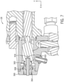
- FIG. 7 shows the mixing chamber assembly 362 when the trigger 316 is pressed. More specifically, FIG. 7 is a schematic side view of a front portion of an embodiment of the spray gun system 28 showing the mix chamber assembly 362 in a "spray" position. In the depicted embodiment, the trigger 316 has been pressed to cause a movement rearward of the mix chamber assembly 362 and interconnected mix tip retainer member 364 and mix tip 360. The mix tip retainer guide assembly 366 remains in place. As the mix chamber assembly 362 moves rearward away from the mix tip retainer guide assembly 366, two fluids enter into the mix chamber assembly 362 via the hose couplers 314 and 354.
- the fluids may then mix in the mix chamber assembly 362 via bores such as the bore 400 to be mixed in the chamber 404 and then to be subsequently sprayed outwardly from the mix tip 360.
- a Zerk or grease fitting 380 may be used to insert a grease or other compound into the mix chamber assembly 362, for example, for temporary storage of the spray gun system 28. The grease may subsequently be expelled by adding air into the mix chamber assembly 362, and spray operations may then resume.
- FIG. 8 is a front view showing an embodiment of the mix chamber assembly 362 showing two lateral bores 400, 402 leading into the chamber 404.
- both of the lateral bores 400, 402 enter the chamber 404 inside of and away from tangent. That is, the lateral bores 400 and 402 enter the chamber 404 inside of tangent lines 406 and 408 respectively.
- Fluid such as compounds A and B, may enter through the lateral bores 400, 402, and then mix inside of the chamber 404.
- pressures of fluid entering the lateral bores 400 and 402 may be equal. That is, if compound A enters via lateral bore 400 and compound B enters via lateral bore 402, pressures at lateral bores 400 and 402 may be the same.
- the fluids may then exit the chamber along the X-axis into the mix tip 360 and out of the spray gun 28 into a desired spray area.
- FIG. 9 is a perspective view depicting an embodiment of a threaded mix chamber assembly 450 and a mix tip 452.
- the threaded mix chamber assembly 450 and a mix tip 452 may not use a mix tip retainer member 364, thus providing for a simpler design with less component parts.
- replacing the mix tip 452 may be more efficiently performed by unscrewing the mix tip 452, for example by using a wrench via a head portion 454 of mix tip 452 to remove the mix tip 452.
- Various mix tips 452 may be provided, for example, having different sizes for an opening 456.
- the opening 456 may be suitable for spraying various types of compound mixes and/or spray patterns.
- the mix tip 452 may be inserted via an opening (e.g., grooved opening) 458 of the threaded mix chamber assembly 450. Threaded portions 460 may then engage grooves in the threaded mix chamber assembly 450 to secure the mix tip 452 in place.
- fluid may enter via bores, such a bore 462, to be mixed in a chamber of the threaded mix chamber assembly 450. Fluid may then exit the chamber into the mix tip 452 to be sprayed outwardly from the opening 456.
Landscapes
- Chemical & Material Sciences (AREA)
- Engineering & Computer Science (AREA)
- Mechanical Engineering (AREA)
- Chemical Kinetics & Catalysis (AREA)
- Physics & Mathematics (AREA)
- Analytical Chemistry (AREA)
- Fluid Mechanics (AREA)
- Electrochemistry (AREA)
- General Chemical & Material Sciences (AREA)
- Materials Engineering (AREA)
- General Physics & Mathematics (AREA)
- Inorganic Chemistry (AREA)
- Automation & Control Theory (AREA)
- Nozzles (AREA)
- Manufacturing & Machinery (AREA)
- Condensed Matter Physics & Semiconductors (AREA)
- Composite Materials (AREA)
- Details Or Accessories Of Spraying Plant Or Apparatus (AREA)
Claims (14)
- Pistolet de pulvérisation (28), comprenant :un ensemble chambre de mélange (362, 450) présentant au moins deux alésages (400, 402) configurés pour recevoir un premier fluide et un second fluide, et une chambre (404) couplée fluidiquement aux au moins deux alésages (400, 402), la chambre (404) étant configurée pour mélanger les premier et second fluides ;une poignée (302) ; etune extension ailée (304) disposée pour entrer en contact avec au moins une partie du dos de la main d'un opérateur lorsque l'opérateur tient le pistolet de pulvérisation par l'intermédiaire de la poignée (302),caractérisé en ce que le pistolet de pulvérisation (28) comprend une sangle (306), dans lequel l'extension ailée (304) comprend une première ouverture (308) configurée pour recevoir une première extrémité de la sangle (306), et dans lequel une seconde extrémité de la sangle (306) s'attache à une partie inférieure de la poignée (302).
- Pistolet de pulvérisation (28) selon la revendication 1, dans lequel l'extension ailée (304) comprend une longueur côte-à-côte faisant entre 5,08 cm et 15,24 cm, ce qui équivaut à entre 2 pouces et 6 pouces.
- Pistolet de pulvérisation (28) selon la revendication 1, dans lequel l'extension ailée (304) comprend une première rainure de dessous configurée pour s'adapter de manière conforme à une partie supérieure du pouce de l'opérateur.
- Pistolet de pulvérisation (28) selon la revendication 3, dans lequel l'extension ailée (304) comprend une seconde rainure de dessous configurée pour s'adapter de manière conforme à une partie supérieure de l'index de l'opérateur.
- Pistolet de pulvérisation (28) selon la revendication 1, dans lequel l'extension ailée (304) comprend une seconde ouverture (310) configurée pour recevoir la première extrémité de la sangle (306), et dans lequel la première extrémité de la sangle peut être insérée dans la première ouverture (308) ou dans la seconde ouverture (310).
- Pistolet de pulvérisation (28) selon la revendication 1, dans lequel le pistolet pulvérisateur (28) comprend un premier raccord de tuyau flexible (314) couplé fluidiquement à un premier alésage inclus dans les au moins deux alésages (400, 402) et configuré pour se coupler à un premier tuyau flexible, et un second raccord de tuyau flexible (354) couplé fluidiquement à un second alésage inclus dans les au moins deux alésages (400, 402) et configuré pour se coupler à un second tuyau flexible.
- Pistolet de pulvérisation (28) selon la revendication 1, comprenant un premier bout de mélange fileté (452), dans lequel l'ensemble chambre de mélange (450) comprend une ouverture rainurée (458) conduisant à la chambre (404), dans lequel l'ouverture rainurée (458) est dimensionnée pour recevoir le premier bout de mélange fileté (452), et dans lequel le premier bout de mélange fileté comprend une première ouverture de pulvérisation destinée à être couplée fluidiquement à la chambre (404) pour pulvériser un fluide mélangé résultant du mélange du premier fluide et du second fluide dans la chambre (404).
- Pistolet de pulvérisation (28) selon la revendication 7, comprenant un second bout de mélange fileté (452) présentant une seconde ouverture de pulvérisation d'une taille différente de celle de la première ouverture de pulvérisation du premier bout de mélange fileté et dans lequel le premier bout de mélange fileté est configuré pour être enlevé de l'ensemble chambre de mélange (450) et remplacé par le second bout de mélange fileté.
- Pistolet de pulvérisation (28) selon la revendication 1, dans lequel le pistolet de pulvérisation (28) n'inclut pas de capuchon d'air.
- Système de distribution de fluide (10), comprenant un pistolet de pulvérisation (28) selon une quelconque revendication précédente,
- Procédé de fabrication d'un pistolet de pulvérisation (28), comprenant :la fabrication d'un ensemble chambre de mélange (362, 450) présentant au moins deux alésages (400, 402) configurés pour recevoir un premier fluide et un second fluide, et une chambre (404) couplée fluidiquement aux au moins deux alésages, la chambre (404) étant configurée pour mélanger les premier et second fluides,la fabrication d'une poignée (302) présentant une extension ailée (304) disposée pour entrer en contact avec au moins une partie du dos de la main d'un opérateur lorsque l'opérateur tient le pistolet de pulvérisation (28) par l'intermédiaire de la poignée (302) ;la fabrication d'un corps de pistolet de pulvérisation (300) ; etla fabrication d'une tête de pistolet de pulvérisation configurée pour recevoir la chambre,caractérisé en ce que l'extension ailée (302) comprend une première et une seconde ouverture (308, 310) configurées pour recevoir une première extrémité d'une sangle, et dans lequel la première extrémité de la sangle peut être insérée dans la première ouverture (308) ou dans la seconde ouverture (310).
- Procédé selon la revendication 11, dans lequel l'extension ailée (304) comprend une longueur côte-à-côte faisant entre 5,08 cm et 15,24 cm, ce qui équivaut à entre 2 pouces et 6 pouces.
- Procédé selon la revendication 11, dans lequel l'extension ailée (304) comprend une première rainure de dessous configurée pour s'adapter de manière conforme à une partie supérieure du pouce de l'opérateur.
- Procédé selon la revendication 13, dans lequel l'extension ailée (304) comprend une seconde rainure de dessous configurée pour s'adapter de manière conforme à une partie supérieure de l'index de l'opérateur.
Applications Claiming Priority (2)
| Application Number | Priority Date | Filing Date | Title |
|---|---|---|---|
| US201962928859P | 2019-10-31 | 2019-10-31 | |
| PCT/US2020/058426 WO2021087410A1 (fr) | 2019-10-31 | 2020-10-30 | Systèmes et procédés pour systèmes de distribution de fluide par pistolet améliorés |
Publications (2)
| Publication Number | Publication Date |
|---|---|
| EP4051438A1 EP4051438A1 (fr) | 2022-09-07 |
| EP4051438B1 true EP4051438B1 (fr) | 2024-10-23 |
Family
ID=73544393
Family Applications (1)
| Application Number | Title | Priority Date | Filing Date |
|---|---|---|---|
| EP20811914.9A Active EP4051438B1 (fr) | 2019-10-31 | 2020-10-30 | Systèmes et procédes pour des systèmes de distribution de produit fluide par pistolet |
Country Status (5)
| Country | Link |
|---|---|
| US (2) | US20240213619A1 (fr) |
| EP (1) | EP4051438B1 (fr) |
| JP (1) | JP7416930B2 (fr) |
| CN (1) | CN114786823B (fr) |
| WO (1) | WO2021087410A1 (fr) |
Families Citing this family (3)
| Publication number | Priority date | Publication date | Assignee | Title |
|---|---|---|---|---|
| US12427488B2 (en) | 2021-07-28 | 2025-09-30 | Philip Zylstra | Multi-component fluid mixing device |
| JP7668527B2 (ja) | 2021-08-18 | 2025-04-25 | 有限会社アスプリ | 拡散及び注入ガンのメンテナンス方法 |
| FR3165321A1 (fr) * | 2024-08-05 | 2026-02-06 | Exel Industries | Méthode de suivi d’une ligne de produit de revêtement, et produit-programme d’ordinateur associé |
Family Cites Families (27)
| Publication number | Priority date | Publication date | Assignee | Title |
|---|---|---|---|---|
| DE1280103B (de) * | 1965-09-18 | 1968-10-10 | Martin Sebastiani | Spritzpistole |
| US3790030A (en) * | 1971-11-08 | 1974-02-05 | F Ives | Liquid resin spray dispensers |
| JPS5837471Y2 (ja) * | 1979-04-25 | 1983-08-24 | 有限会社 立野製作所 | スプレ−ガン用ホ−スの保持バンド |
| EP0127014A3 (fr) * | 1983-05-31 | 1986-02-19 | Lloyd T. Smith | Poignée pour outils à main |
| US5236129A (en) * | 1992-05-27 | 1993-08-17 | Ransburg Corporation | Ergonomic hand held paint spray gun |
| US5639027A (en) * | 1994-12-08 | 1997-06-17 | Ransburg Corporation | Two component external mix spray gun |
| US6158624A (en) * | 1997-08-07 | 2000-12-12 | The Clayton Corporation | Foam dispensing gun |
| US5991956A (en) * | 1998-02-05 | 1999-11-30 | Chapman; John | Paint brush grip |
| US6070809A (en) * | 1998-10-26 | 2000-06-06 | Price; Charles Keith | Spray gun stand and support |
| US7318554B2 (en) * | 2001-10-25 | 2008-01-15 | Langeman Gary D | Third stream automotive color injection |
| US20050035220A1 (en) * | 2003-08-11 | 2005-02-17 | Brown Daniel P. | Multi-component fluid nozzle assembly with detachable nozzle spray tip |
| US20080148523A1 (en) * | 2006-09-28 | 2008-06-26 | Macgregor Shane | Mobile device with handle |
| US20080235912A1 (en) * | 2007-03-27 | 2008-10-02 | Travel Caddy, Inc. D/B/A Travelon | Luggage handle |
| TW201132415A (en) * | 2010-03-17 | 2011-10-01 | Yuan Mei Corp | Switch structure for water outlet of spray gun |
| US20120012677A1 (en) * | 2010-07-16 | 2012-01-19 | Crossley Iii L T Tom | Spray gun handle support and quick release trigger assembly |
| US9931745B2 (en) * | 2011-09-08 | 2018-04-03 | Galaxg, Llc | Ergonomic hand tool holders and systems |
| US20140346257A1 (en) * | 2013-05-23 | 2014-11-27 | Finishing Brands Holdings Inc. | Spray Tool Locking System |
| US20150174598A1 (en) * | 2013-12-20 | 2015-06-25 | Techtronic Outdoor Products Technology Limited | Spray gun for use with a pressure washer |
| US9539718B2 (en) * | 2014-12-19 | 2017-01-10 | Jeffery Hall | Ergonomic handle for a fluid applicator spray gun |
| CA2879311C (fr) * | 2015-01-22 | 2016-10-18 | Mac & Mac Hydrodemolition Inc. | Dispositif de protection destine a un appareil d'hydrodemolition |
| US10324428B2 (en) | 2015-02-12 | 2019-06-18 | Carlisle Fluid Technologies, Inc. | Intra-shop connectivity system |
| US10589308B2 (en) * | 2015-04-30 | 2020-03-17 | Wagner Spray Tech Corporation | Finger rest for a liquid applicator |
| US10702877B2 (en) * | 2016-11-09 | 2020-07-07 | Pedero Pipe Support Systems Usa, Lp | High-volume foam spray gun |
| CN106311515A (zh) * | 2016-11-16 | 2017-01-11 | 天津福禄机电设备有限公司 | 高压水手持喷枪 |
| US10293354B2 (en) * | 2016-12-21 | 2019-05-21 | Misty Mate, Inc. | Handheld misting device with pressure-relieving handle |
| US11213840B2 (en) * | 2017-05-01 | 2022-01-04 | Wagner Spray Tech Corporation | Mixer design for a plural component system |
| CN208873153U (zh) * | 2018-10-22 | 2019-05-17 | 广州艾韦迅信息科技有限公司 | 一种可调节手持终端 |
-
2020
- 2020-10-30 WO PCT/US2020/058426 patent/WO2021087410A1/fr not_active Ceased
- 2020-10-30 JP JP2022525296A patent/JP7416930B2/ja active Active
- 2020-10-30 EP EP20811914.9A patent/EP4051438B1/fr active Active
- 2020-10-30 CN CN202080075584.2A patent/CN114786823B/zh active Active
-
2024
- 2024-03-07 US US18/598,182 patent/US20240213619A1/en active Pending
-
2025
- 2025-11-26 US US19/402,401 patent/US20260077318A1/en active Pending
Also Published As
| Publication number | Publication date |
|---|---|
| EP4051438A1 (fr) | 2022-09-07 |
| US20240213619A1 (en) | 2024-06-27 |
| US20260077318A1 (en) | 2026-03-19 |
| CN114786823A (zh) | 2022-07-22 |
| JP7416930B2 (ja) | 2024-01-17 |
| WO2021087410A1 (fr) | 2021-05-06 |
| JP2022554278A (ja) | 2022-12-28 |
| CN114786823B (zh) | 2024-11-08 |
Similar Documents
| Publication | Publication Date | Title |
|---|---|---|
| US20240213619A1 (en) | Systems and Methods For Improved Fluid Gun Delivery Systems | |
| EP3655168B1 (fr) | Systèmes et méthodes de contrôle amélioré de mélange par impact | |
| JP6989687B2 (ja) | 流体比率制御のためのシステム及び方法 | |
| CN106232240A (zh) | 改进的低压2k手持式喷枪 | |
| EP3463687A1 (fr) | Système de distribution d'un produit expansible pulvérisable | |
| US20080257979A1 (en) | Plural component purging system | |
| WO2012013574A1 (fr) | Appareil de pulvérisation de liquides comportant une télécommande par radio | |
| US20180104854A1 (en) | Flat fan spraying apparatus for the dispensing of ultra-high fast set two component materials | |
| US20240261810A1 (en) | Spray gun applicator | |
| WO2004101167A1 (fr) | Dispositif pour pulveriser une surface | |
| KR101016180B1 (ko) | 히팅부가 구비된 스프레이건 | |
| US20160256880A1 (en) | Pressure washing system with selective fluid injection features | |
| EP2542348B1 (fr) | Procédé et système pour le revêtement d'une surface d'un matériau de revêtement visqueux à un seul composant ou plusieurs composants | |
| US20110274847A1 (en) | Universal actuator for coatings | |
| JP4749031B2 (ja) | 塗料自動供給式刷毛装置 | |
| KR20110115451A (ko) | 이액형 도료공급장치와 혼합장치를 구비한 도장 시스템. | |
| JPH11267554A (ja) | 二液混合式スプレー方法およびその装置 | |
| KR100941500B1 (ko) | 혼합비율 조절형식의 초소형 경량 이액형 수동 도장장치 | |
| JP2022000323A (ja) | 塗膜除去用エア回転工具およびエア回転工具使用方法 | |
| JP2022165511A (ja) | 塗布装置、製造システム、塗布装置の制御方法および塗布装置の調整方法 | |
| WO2001096005A1 (fr) | Melange de liquides sous pression | |
| GB2305472A (en) | Paint dispenser for chipped paintwork | |
| JPH10314687A (ja) | 洗浄方法およびその装置 |
Legal Events
| Date | Code | Title | Description |
|---|---|---|---|
| STAA | Information on the status of an ep patent application or granted ep patent |
Free format text: STATUS: UNKNOWN |
|
| STAA | Information on the status of an ep patent application or granted ep patent |
Free format text: STATUS: THE INTERNATIONAL PUBLICATION HAS BEEN MADE |
|
| PUAI | Public reference made under article 153(3) epc to a published international application that has entered the european phase |
Free format text: ORIGINAL CODE: 0009012 |
|
| STAA | Information on the status of an ep patent application or granted ep patent |
Free format text: STATUS: REQUEST FOR EXAMINATION WAS MADE |
|
| 17P | Request for examination filed |
Effective date: 20220520 |
|
| AK | Designated contracting states |
Kind code of ref document: A1 Designated state(s): AL AT BE BG CH CY CZ DE DK EE ES FI FR GB GR HR HU IE IS IT LI LT LU LV MC MK MT NL NO PL PT RO RS SE SI SK SM TR |
|
| DAV | Request for validation of the european patent (deleted) | ||
| DAX | Request for extension of the european patent (deleted) | ||
| GRAP | Despatch of communication of intention to grant a patent |
Free format text: ORIGINAL CODE: EPIDOSNIGR1 |
|
| STAA | Information on the status of an ep patent application or granted ep patent |
Free format text: STATUS: GRANT OF PATENT IS INTENDED |
|
| RIC1 | Information provided on ipc code assigned before grant |
Ipc: B05B 15/65 20180101ALN20240422BHEP Ipc: B05B 12/14 20060101ALN20240422BHEP Ipc: B05B 12/10 20060101ALN20240422BHEP Ipc: B05B 12/08 20060101ALN20240422BHEP Ipc: B05B 7/24 20060101ALN20240422BHEP Ipc: B05B 7/12 20060101ALN20240422BHEP Ipc: B05B 7/00 20060101ALN20240422BHEP Ipc: B05B 7/16 20060101ALN20240422BHEP Ipc: B05B 7/04 20060101ALN20240422BHEP Ipc: G05D 11/13 20060101ALI20240422BHEP Ipc: B29B 7/82 20060101ALI20240422BHEP Ipc: B29B 7/74 20060101ALI20240422BHEP Ipc: B29B 7/72 20060101ALI20240422BHEP Ipc: B25G 1/10 20060101ALI20240422BHEP Ipc: B05B 12/00 20180101ALI20240422BHEP Ipc: B05B 15/63 20180101AFI20240422BHEP |
|
| RIC1 | Information provided on ipc code assigned before grant |
Ipc: B05B 15/65 20180101ALN20240430BHEP Ipc: B05B 12/14 20060101ALN20240430BHEP Ipc: B05B 12/10 20060101ALN20240430BHEP Ipc: B05B 12/08 20060101ALN20240430BHEP Ipc: B05B 7/24 20060101ALN20240430BHEP Ipc: B05B 7/12 20060101ALN20240430BHEP Ipc: B05B 7/00 20060101ALN20240430BHEP Ipc: B05B 7/16 20060101ALN20240430BHEP Ipc: B05B 7/04 20060101ALN20240430BHEP Ipc: G05D 11/13 20060101ALI20240430BHEP Ipc: B29B 7/82 20060101ALI20240430BHEP Ipc: B29B 7/74 20060101ALI20240430BHEP Ipc: B29B 7/72 20060101ALI20240430BHEP Ipc: B25G 1/10 20060101ALI20240430BHEP Ipc: B05B 12/00 20180101ALI20240430BHEP Ipc: B05B 15/63 20180101AFI20240430BHEP |
|
| INTG | Intention to grant announced |
Effective date: 20240514 |
|
| GRAS | Grant fee paid |
Free format text: ORIGINAL CODE: EPIDOSNIGR3 |
|
| GRAA | (expected) grant |
Free format text: ORIGINAL CODE: 0009210 |
|
| STAA | Information on the status of an ep patent application or granted ep patent |
Free format text: STATUS: THE PATENT HAS BEEN GRANTED |
|
| AK | Designated contracting states |
Kind code of ref document: B1 Designated state(s): AL AT BE BG CH CY CZ DE DK EE ES FI FR GB GR HR HU IE IS IT LI LT LU LV MC MK MT NL NO PL PT RO RS SE SI SK SM TR |
|
| REG | Reference to a national code |
Ref country code: GB Ref legal event code: FG4D |
|
| REG | Reference to a national code |
Ref country code: CH Ref legal event code: EP |
|
| REG | Reference to a national code |
Ref country code: DE Ref legal event code: R096 Ref document number: 602020039989 Country of ref document: DE |
|
| REG | Reference to a national code |
Ref country code: IE Ref legal event code: FG4D |
|
| REG | Reference to a national code |
Ref country code: LT Ref legal event code: MG9D |
|
| REG | Reference to a national code |
Ref country code: NL Ref legal event code: MP Effective date: 20241023 |
|
| REG | Reference to a national code |
Ref country code: AT Ref legal event code: MK05 Ref document number: 1734415 Country of ref document: AT Kind code of ref document: T Effective date: 20241023 |
|
| PG25 | Lapsed in a contracting state [announced via postgrant information from national office to epo] |
Ref country code: NL Free format text: LAPSE BECAUSE OF FAILURE TO SUBMIT A TRANSLATION OF THE DESCRIPTION OR TO PAY THE FEE WITHIN THE PRESCRIBED TIME-LIMIT Effective date: 20241023 |
|
| PG25 | Lapsed in a contracting state [announced via postgrant information from national office to epo] |
Ref country code: NL Free format text: LAPSE BECAUSE OF FAILURE TO SUBMIT A TRANSLATION OF THE DESCRIPTION OR TO PAY THE FEE WITHIN THE PRESCRIBED TIME-LIMIT Effective date: 20241023 |
|
| PG25 | Lapsed in a contracting state [announced via postgrant information from national office to epo] |
Ref country code: PT Free format text: LAPSE BECAUSE OF FAILURE TO SUBMIT A TRANSLATION OF THE DESCRIPTION OR TO PAY THE FEE WITHIN THE PRESCRIBED TIME-LIMIT Effective date: 20250224 Ref country code: IS Free format text: LAPSE BECAUSE OF FAILURE TO SUBMIT A TRANSLATION OF THE DESCRIPTION OR TO PAY THE FEE WITHIN THE PRESCRIBED TIME-LIMIT Effective date: 20250223 Ref country code: HR Free format text: LAPSE BECAUSE OF FAILURE TO SUBMIT A TRANSLATION OF THE DESCRIPTION OR TO PAY THE FEE WITHIN THE PRESCRIBED TIME-LIMIT Effective date: 20241023 |
|
| PG25 | Lapsed in a contracting state [announced via postgrant information from national office to epo] |
Ref country code: FI Free format text: LAPSE BECAUSE OF FAILURE TO SUBMIT A TRANSLATION OF THE DESCRIPTION OR TO PAY THE FEE WITHIN THE PRESCRIBED TIME-LIMIT Effective date: 20241023 |
|
| PG25 | Lapsed in a contracting state [announced via postgrant information from national office to epo] |
Ref country code: BG Free format text: LAPSE BECAUSE OF FAILURE TO SUBMIT A TRANSLATION OF THE DESCRIPTION OR TO PAY THE FEE WITHIN THE PRESCRIBED TIME-LIMIT Effective date: 20241023 |
|
| PG25 | Lapsed in a contracting state [announced via postgrant information from national office to epo] |
Ref country code: ES Free format text: LAPSE BECAUSE OF FAILURE TO SUBMIT A TRANSLATION OF THE DESCRIPTION OR TO PAY THE FEE WITHIN THE PRESCRIBED TIME-LIMIT Effective date: 20241023 |
|
| PG25 | Lapsed in a contracting state [announced via postgrant information from national office to epo] |
Ref country code: NO Free format text: LAPSE BECAUSE OF FAILURE TO SUBMIT A TRANSLATION OF THE DESCRIPTION OR TO PAY THE FEE WITHIN THE PRESCRIBED TIME-LIMIT Effective date: 20250123 |
|
| PG25 | Lapsed in a contracting state [announced via postgrant information from national office to epo] |
Ref country code: LV Free format text: LAPSE BECAUSE OF FAILURE TO SUBMIT A TRANSLATION OF THE DESCRIPTION OR TO PAY THE FEE WITHIN THE PRESCRIBED TIME-LIMIT Effective date: 20241023 Ref country code: AT Free format text: LAPSE BECAUSE OF FAILURE TO SUBMIT A TRANSLATION OF THE DESCRIPTION OR TO PAY THE FEE WITHIN THE PRESCRIBED TIME-LIMIT Effective date: 20241023 Ref country code: GR Free format text: LAPSE BECAUSE OF FAILURE TO SUBMIT A TRANSLATION OF THE DESCRIPTION OR TO PAY THE FEE WITHIN THE PRESCRIBED TIME-LIMIT Effective date: 20250124 |
|
| PG25 | Lapsed in a contracting state [announced via postgrant information from national office to epo] |
Ref country code: PL Free format text: LAPSE BECAUSE OF FAILURE TO SUBMIT A TRANSLATION OF THE DESCRIPTION OR TO PAY THE FEE WITHIN THE PRESCRIBED TIME-LIMIT Effective date: 20241023 |
|
| PG25 | Lapsed in a contracting state [announced via postgrant information from national office to epo] |
Ref country code: RS Free format text: LAPSE BECAUSE OF FAILURE TO SUBMIT A TRANSLATION OF THE DESCRIPTION OR TO PAY THE FEE WITHIN THE PRESCRIBED TIME-LIMIT Effective date: 20250123 |
|
| REG | Reference to a national code |
Ref country code: CH Ref legal event code: PL |
|
| PG25 | Lapsed in a contracting state [announced via postgrant information from national office to epo] |
Ref country code: SM Free format text: LAPSE BECAUSE OF FAILURE TO SUBMIT A TRANSLATION OF THE DESCRIPTION OR TO PAY THE FEE WITHIN THE PRESCRIBED TIME-LIMIT Effective date: 20241023 |
|
| PG25 | Lapsed in a contracting state [announced via postgrant information from national office to epo] |
Ref country code: MC Free format text: LAPSE BECAUSE OF FAILURE TO SUBMIT A TRANSLATION OF THE DESCRIPTION OR TO PAY THE FEE WITHIN THE PRESCRIBED TIME-LIMIT Effective date: 20241023 |
|
| PG25 | Lapsed in a contracting state [announced via postgrant information from national office to epo] |
Ref country code: DK Free format text: LAPSE BECAUSE OF FAILURE TO SUBMIT A TRANSLATION OF THE DESCRIPTION OR TO PAY THE FEE WITHIN THE PRESCRIBED TIME-LIMIT Effective date: 20241023 |
|
| PG25 | Lapsed in a contracting state [announced via postgrant information from national office to epo] |
Ref country code: LU Free format text: LAPSE BECAUSE OF NON-PAYMENT OF DUE FEES Effective date: 20241030 Ref country code: BE Free format text: LAPSE BECAUSE OF NON-PAYMENT OF DUE FEES Effective date: 20241031 |
|
| PG25 | Lapsed in a contracting state [announced via postgrant information from national office to epo] |
Ref country code: EE Free format text: LAPSE BECAUSE OF FAILURE TO SUBMIT A TRANSLATION OF THE DESCRIPTION OR TO PAY THE FEE WITHIN THE PRESCRIBED TIME-LIMIT Effective date: 20241023 |
|
| PG25 | Lapsed in a contracting state [announced via postgrant information from national office to epo] |
Ref country code: CH Free format text: LAPSE BECAUSE OF NON-PAYMENT OF DUE FEES Effective date: 20241031 |
|
| PG25 | Lapsed in a contracting state [announced via postgrant information from national office to epo] |
Ref country code: RO Free format text: LAPSE BECAUSE OF FAILURE TO SUBMIT A TRANSLATION OF THE DESCRIPTION OR TO PAY THE FEE WITHIN THE PRESCRIBED TIME-LIMIT Effective date: 20241023 |
|
| REG | Reference to a national code |
Ref country code: DE Ref legal event code: R097 Ref document number: 602020039989 Country of ref document: DE |
|
| PG25 | Lapsed in a contracting state [announced via postgrant information from national office to epo] |
Ref country code: SK Free format text: LAPSE BECAUSE OF FAILURE TO SUBMIT A TRANSLATION OF THE DESCRIPTION OR TO PAY THE FEE WITHIN THE PRESCRIBED TIME-LIMIT Effective date: 20241023 |
|
| PG25 | Lapsed in a contracting state [announced via postgrant information from national office to epo] |
Ref country code: CZ Free format text: LAPSE BECAUSE OF FAILURE TO SUBMIT A TRANSLATION OF THE DESCRIPTION OR TO PAY THE FEE WITHIN THE PRESCRIBED TIME-LIMIT Effective date: 20241023 |
|
| PG25 | Lapsed in a contracting state [announced via postgrant information from national office to epo] |
Ref country code: IT Free format text: LAPSE BECAUSE OF FAILURE TO SUBMIT A TRANSLATION OF THE DESCRIPTION OR TO PAY THE FEE WITHIN THE PRESCRIBED TIME-LIMIT Effective date: 20241023 |
|
| REG | Reference to a national code |
Ref country code: BE Ref legal event code: MM Effective date: 20241031 |
|
| PLBE | No opposition filed within time limit |
Free format text: ORIGINAL CODE: 0009261 |
|
| STAA | Information on the status of an ep patent application or granted ep patent |
Free format text: STATUS: NO OPPOSITION FILED WITHIN TIME LIMIT |
|
| PG25 | Lapsed in a contracting state [announced via postgrant information from national office to epo] |
Ref country code: SE Free format text: LAPSE BECAUSE OF FAILURE TO SUBMIT A TRANSLATION OF THE DESCRIPTION OR TO PAY THE FEE WITHIN THE PRESCRIBED TIME-LIMIT Effective date: 20241023 |
|
| 26N | No opposition filed |
Effective date: 20250724 |
|
| PG25 | Lapsed in a contracting state [announced via postgrant information from national office to epo] |
Ref country code: FR Free format text: LAPSE BECAUSE OF NON-PAYMENT OF DUE FEES Effective date: 20241223 |
|
| PG25 | Lapsed in a contracting state [announced via postgrant information from national office to epo] |
Ref country code: IE Free format text: LAPSE BECAUSE OF NON-PAYMENT OF DUE FEES Effective date: 20241030 |
|
| PGFP | Annual fee paid to national office [announced via postgrant information from national office to epo] |
Ref country code: DE Payment date: 20251029 Year of fee payment: 6 |
|
| PGFP | Annual fee paid to national office [announced via postgrant information from national office to epo] |
Ref country code: GB Payment date: 20251027 Year of fee payment: 6 |
|
| PG25 | Lapsed in a contracting state [announced via postgrant information from national office to epo] |
Ref country code: HU Free format text: LAPSE BECAUSE OF FAILURE TO SUBMIT A TRANSLATION OF THE DESCRIPTION OR TO PAY THE FEE WITHIN THE PRESCRIBED TIME-LIMIT; INVALID AB INITIO Effective date: 20201030 |
|
| PG25 | Lapsed in a contracting state [announced via postgrant information from national office to epo] |
Ref country code: CY Free format text: LAPSE BECAUSE OF FAILURE TO SUBMIT A TRANSLATION OF THE DESCRIPTION OR TO PAY THE FEE WITHIN THE PRESCRIBED TIME-LIMIT; INVALID AB INITIO Effective date: 20201030 |