EP4051868B1 - Dispositif de séparation et procédé et installation associés - Google Patents
Dispositif de séparation et procédé et installation associés Download PDFInfo
- Publication number
- EP4051868B1 EP4051868B1 EP19870054.4A EP19870054A EP4051868B1 EP 4051868 B1 EP4051868 B1 EP 4051868B1 EP 19870054 A EP19870054 A EP 19870054A EP 4051868 B1 EP4051868 B1 EP 4051868B1
- Authority
- EP
- European Patent Office
- Prior art keywords
- chamber
- diver
- fluid
- phase
- separation device
- Prior art date
- Legal status (The legal status is an assumption and is not a legal conclusion. Google has not performed a legal analysis and makes no representation as to the accuracy of the status listed.)
- Active
Links
Images




Classifications
-
- E—FIXED CONSTRUCTIONS
- E21—EARTH OR ROCK DRILLING; MINING
- E21B—EARTH OR ROCK DRILLING; OBTAINING OIL, GAS, WATER, SOLUBLE OR MELTABLE MATERIALS OR A SLURRY OF MINERALS FROM WELLS
- E21B43/00—Methods or apparatus for obtaining oil, gas, water, soluble or meltable materials or a slurry of minerals from wells
- E21B43/34—Arrangements for separating materials produced by the well
-
- B—PERFORMING OPERATIONS; TRANSPORTING
- B01—PHYSICAL OR CHEMICAL PROCESSES OR APPARATUS IN GENERAL
- B01D—SEPARATION
- B01D17/00—Separation of liquids, not provided for elsewhere, e.g. by thermal diffusion
- B01D17/02—Separation of non-miscible liquids
- B01D17/0208—Separation of non-miscible liquids by sedimentation
- B01D17/0214—Separation of non-miscible liquids by sedimentation with removal of one of the phases
-
- B—PERFORMING OPERATIONS; TRANSPORTING
- B01—PHYSICAL OR CHEMICAL PROCESSES OR APPARATUS IN GENERAL
- B01D—SEPARATION
- B01D17/00—Separation of liquids, not provided for elsewhere, e.g. by thermal diffusion
- B01D17/12—Auxiliary equipment particularly adapted for use with liquid-separating apparatus, e.g. control circuits
Definitions
- the present invention concerns a separation device for extracting a sample from a fluid flow comprising at least three phases including at least a phase of interest to be sampled.
- the invention also concerns a corresponding separation method, and an installation for producing a fluid, comprising the aforementioned separation device.
- Separation devices are commonly used in the oilfield industry, on fluid production installations.
- the produced fluid is extracted from at least one well and usually comprises a mix of oil, water and gas.
- allocation There are several methods for analyzing an oil sample in order to determine the respective proportions of fluid from each reservoir in the sample, usually by comparing one or more of its characteristic features with the corresponding features of purified oil samples from each reservoir. Such a method is referred to as allocation.
- the fluid produced at the wellhead generally comprises at least three different phases, including gas, water and oil.
- the fluid is usually purified through a sampler module, in order to obtain a sample containing a higher proportion of oil and lower proportions of gas and water.
- WO 2012/154971 A2 describes a method and system for metering liquid production at a well.
- US 2019/211662 A1 describes a controlled high pressure separator for production fluids.
- One aim of the invention is thus to provide a separation device able to extract a sample comprising at least a predetermined proportion of a single phase from a multiphase flow, able to safely operate close to a wellhead, and allowing for a fast and reliable obtaining of purified fluid samples for further analysis.
- the subject-matter of the invention is a separation device according to claim 1.
- the separation device according to the invention may comprise one or more of the features of claims 2 to 9.
- the invention also concerns an installation for producing a fluid according to claim 10.
- the installation according to the invention may comprise one or more of the features of claims 11 to 13.
- the invention further concerns a method according to claim 14.
- the method according to the invention may comprise one or more of the features of claims 15 or 16.
- FIG. 10 An installation 10 for producing a fluid is represented on figure 1 .
- the fluid is produced from a plurality of different sources, each source producing a differentiable fluid from the other sources.
- the installation 10 is for example an installation for producing oil and gas, comprising a well 12 and a wellhead 14 at the top of the well 12, the sources being a plurality of reservoirs from which fluid is produced.
- the well 12 advantageously comprises a casing 18 placed in a hole extending through the ground 16.
- the hole crosses the plurality of reservoirs A, B containing the fluid, including hydrocarbons in liquid and gas form, as well as water and other fluids, trapped in rock formations.
- each reservoir A, B is different from the fluid produced from the other reservoirs A, B, notably having different proportions of varied hydrocarbons or other chemical species. Hence, produced fluids exhibit a different chemical signature depending on which reservoir A, B they are produced from.
- the well 12 extends sensibly vertically at least in an upper portion.
- the well 12 further may comprises a deviated lower portion extending at an angle with the vertical upper portion, the angle being comprised between 0° and up to 90° for a horizontal well.
- the well 12 comprises several transverse perforations 20 extending from the casing 18 through the reservoirs A, B, destined to allow fluid from the reservoirs A, B to flow through the rock into the casing 18 and up to the wellhead 14.
- the fluid produced at the wellhead 14 comprises at least one phase, including in particular a water phase, an oil phase and a gas phase.
- the produced fluid comprises only a water phase, only an oil phase or only a gas phase, or only two phases chosen from the above.
- the fluid may also comprise a solid phase, for example sand or sediments.
- the wellhead 14 comprises a filtering assembly, suitable for removing the solid phase from the produced fluid flow.
- the produced fluid comprises several phases
- at least two of the phases are sensibly immiscible with one another.
- miscibility coefficient of the phases is for example lower than 5% at 25°C and under 1013 hPa.
- a fluid analysis system 22 is fluidically connected to the wellhead 14, and able to extract samples of the produced fluid for analysis, in a continuous manner and without altering the production process.
- the fluid analysis system 22 is configured to analyze samples from the fluid produced at the wellhead 14 to determine a relative proportion of fluid extracted from each reservoir A, B among the produced fluid. More specifically, the fluid analysis system 22 is configured to prepare and analyze samples comprising a high proportion of a phase of interest comprised among the phases of the produced fluid, in particular the oil phase.
- the fluid analysis system 22 is configured to extract samples comprising at least 80% of oil in volume, advantageously at least 90% of oil in volume, from the produced fluid, which may originally comprise any proportion of each of the phases.
- the fluid analysis system 22 comprises a sampler module 24, a separation device 26, an analysis module 28, a control module 30 and a pneumatic interface 32.
- the sampler module 24 is configured to extract fluid samples from the fluid produced at the wellhead 14, and to remove at least a part of each phase other than the phase of interest from each fluid sample.
- the detailed features of the sampler module 24 are known to the person skilled in the art and thus are not discussed in details hereinafter. Examples of sampler modules for multi-phasic fluids are sold by Typhonix and Expro, among others.
- the sampler module 24 has an outlet fluidically connected to the separation device 26, which conveys the fluid samples for further improvement of the concentration in the phase of interest.
- the sampler module 24 is fully pneumatically controlled by the control module 30 through the pneumatic interface 32.
- the sampler module 24 is thus devoid of electrically controlled components, and is contained in an enclosure suitable for use in an explosive atmosphere environment, so that the sampler module 24 can be located close to the wellhead 14 with reduced risk.
- the separation device 26 is configured to extract samples from the flow exiting the sampler 24, with an increased relative proportion of the phase of interest, in order to improve the accuracy of the analysis performed by the analysis module 28.
- the separation device 26 is advantageously contained in a portable enclosure, notably together with the analysis module 28, in which a neutral gas flow circulates, for example a nitrogen flow.
- a neutral gas flow circulates, for example a nitrogen flow.
- the nitrogen flow prevents combustion and makes the separation device 26 and analysis device 28 usable in an explosive atmosphere, like close to a wellhead.
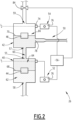
- the separation device 26 is shown in details on figures 2 and 3 .
- the separation device 26 comprises a chamber assembly configured to receive the fluid exiting the sampler module 24, as well as a first diver 44 and a second diver 46.
- the chamber assembly may comprise a single chamber, or a plurality of chambers fluidically connected to each other in succession.
- the chamber assembly comprises a first chamber 40 and a second chamber 42, the first diver 44 and the second diver 46 being respectively located in the first chamber 40 and in the second chamber 42.
- the separation device 26 further comprises an extraction device 50 configured to extract the fluid contained in the chamber assembly to form a sample, as well as a first sensor 52, a second sensor 54 and a control device 56.
- the extraction device 50 is also configured to convey the extracted sample towards the analysis module 28 to implement the analysis.
- the first chamber 40 comprises an inlet 58 fluidically connected to the sampler module 24, through which the fluid enters the first chamber 40, and an outlet 55 opening in the first chamber 40 preferably opposite the inlet 58.
- the second chamber presents an inlet 57 opening in the second chamber 42 and an outlet 59 opposite the inlet 57, through which the fluid exits the second chamber 42.
- the outlet 55 of the first chamber 40 and the inlet 57 of the second chamber 42 are fluidically connected to each other through a conduit 60.
- the fist chamber 40 and the second chamber 42 are for example sensibly cylindrical in shape, with the inlet 58 and the outlet 55 of the first chamber 40, as well as the inlet 57 and the outlet 59 of the second chamber 42 sensibly aligned on their respective axis.
- the fist chamber 40 and the second chamber 42 may have in particular identical height and diameter, and the conduit 60 has a diameter preferentially smaller than the diameter of the first chamber 40 and the second chamber 42.
- the inlets 57, 58, the outlets 55, 59 and the conduit 60 are aligned on a single vertical axis, so that the different phases are arranged in the first chamber 40 and second chamber 42 relatively to their respective densities, with denser phases closer to the inlet 58 of the first chamber 40 and lighter phases closer to the outlet 59 of the second chamber 42.
- the inlet 58 opens in the top wall of the chamber assembly, or in a side wall.
- inlets 57, 58 and outlets 55, 59 are not aligned. This is particularly relevant if the conduit 60 is flexible and the first chamber 40 and second chamber 42 are separate, or even remote from each other.
- the first chamber 40 and the second chamber 42 receive the multi-phase fluid from the sampler module 24.
- the fluid received in the first chamber 40 and in the second chamber 42 comprises at least a first phase 62, for example a water phase, a second phase 64, for example an oil phase, and a third phase 66, for example a gas phase.
- the three phases present different respective densities, with the first phase being the densest and the third phase the least dense.
- the three phases are arranged in the first chamber 40 and second chamber 42 relative to each other with respect to their relative densities, with a first interface 68 separating the first phase 62 and the second phase 64, and a second interface 70 separating the second phase 64 and the third phase 66.
- the first diver 44 is located in the first chamber 40.
- the first diver 44 presents a first density greater that the density of the phase of interest, so that the first diver 44 sinks when placed in the phase of interest.
- the first density is smaller than the density of at least one of the phases of the multi-phase fluid apart from the phase of interest.
- the first density of the first diver 44 is smaller than the density of the first phase 62 and greater than the respective densities of the second phase 64 and the third phase 66. This way, the first diver 44 float on the first phase 62 and sinks in the second and/or third phase 64, 66, so that the first diver 44 follows the first interface 68.
- the second diver 46 is located in the second chamber 42.
- the second diver 46 presents a second density smaller that the density of the phase of interest, so that the second diver 46 floats when placed in the phase of interest.
- the second density is greater than the density of at least one of the phases of the multi-phase fluid apart from the phase of interest.
- the second density of the second diver 46 is smaller than the respective densities of the first phase 62 and the second phase 64 and greater than the density of the third phase 66. This way, the second diver 46 floats on the first phase 62 and/or the second phase 64 and sinks in the third phase 66, so that the second diver 46 follows the second interface 70.
- first diver 44 is denser than oil but less dense than water and the second diver 46 is denser than gas but less dense than oil, so that the first diver 44 and the second diver 46 follow the interfaces of the oil phase in a three-phase fluid.
- the first diver 44 and the second diver 46 are for example substantially cylindrical in shape, with diameters smaller than the diameters of the first chamber 40 and second chamber 42, so as to not block the fluid flow, and greater than the diameters of the inlet 58, outlet 59 and conduit 60, so as to remain in their respective chamber 40, 42.
- the fluid circulates in the first chamber 40 and in the second chamber 42 under an injection pressure resulting from the pressure differential between the fluid exiting the wellhead 14 and the atmospheric pressure.
- the fluid enters the chamber assembly with a pressure lower than the pressure at the wellhead by 3 to 4 bar, but sufficient for circulation the fluid through the chamber assembly.
- the injection pressure is for example greater than 6 bar and advantageously comprised between 20 bar and 60 bar relative to the atmospheric pressure. This ensures that the volume occupied by gaseous phases of the fluid remains low.
- the chamber assembly comprises a pressure sensor (not represented), configured to measure a pressure in the first chamber 40 and/or in the second chamber 42.
- the pressure sensor allows checking the presence of pressurized gas in the chamber assembly.
- the first sensor 52 and the second sensor 54 are respectively arranged in the first chamber 40 and in the second chamber 42.
- the first sensor 52 is configured to detect the first diver 44 reaching a predetermined first level l 1 in the first chamber 40
- the second sensor 54 is configured to detect the second diver 46 reaching a predetermined second level l 2 in the second chamber 42.
- the first level l 1 is predetermined close to the outlet 55, in an upper part of the first chamber 40, while the second level l 2 is predetermined close to the outlet 59, in an upper part of the second chamber 42.
- the first sensor 52 and the second sensor 54 comprise each a magnetic sensor 74, disposed at the first outlet 55 and second outlet 59 respectively.
- the first diver 44 and the second diver 46 each comprise at least a magnetic part, able to be detected by the magnetic sensors 74 without requiring direct contact.
- the magnetic sensor is configured to detect a magnetic field perturbation caused by proximity of the first diver 44 or second diver 46.
- the first sensor 52 and the second sensor 54 also comprise signaling modules 76 connected to their respective magnetic sensor 74 and configured to signal proximity between the first diver 44 or second diver 46 respectively and the magnetic sensor 74.
- the first level l 1 and the second level l 2 thus respectively correspond to the position in which the first diver 44 and the second diver 46 are in proximity with the respective magnetic sensors 74, as visible on figure 3 .
- proximity it is meant that the distance between the first diver 44 or second diver 46 and the magnetic sensor 74 is low enough to allow detection without error. For example, such a distance is lower than 2 mm.
- the first diver 44 reaching the first level l 1 is representative of the second chamber 42 containing only phases 64 and/or 66 of the fluid that are less dense than the first diver 44.
- the first diver 44 reaching the first level l 1 signals that the interface separating the water phase 62 and the oil phase 64 has reached the first level l 1 , the first chamber 40 containing the water phase.
- the second chamber 42 thus contains mostly the oil phase 64 and the gas phase 66, or only the gas phase or the oil phase.
- the first diver 44 not being detected by the first sensor 52 signifies that the second chamber 42 contains the oil phase 64 and eventually the gas phase 66.
- the second diver 46 reaching the second level l 2 is representative of the first chamber 40 and second chamber 42 containing only phases 62 and/or 64 of the fluid that are denser than the second diver 46.
- the second diver 46 reaching the second level l 2 signals that the interface separating the oil phase 64 and the gas phase 66 has reached the second level l 2 , the first chamber 40 and second chamber 42 containing mostly the water phase 62 and the oil phase 64, or only the water phase or the oil phase.
- the first diver 44 not reaching the first level l 1 and the second diver 46 simultaneously reaching the second level l 2 signals that the second chamber 42 mostly contains phases whose densities are comprised between the first density and the second density.
- first level l 1 and the second level l 2 are adjustable in the first chamber 40 and in the second chamber 42 respectively.
- the magnetic sensors 74 are movable along the walls of the first chamber 40 and the second chamber 42 respectively, so as to modify the positions detection of the first diver 44 and second diver 46 respectively.
- Adjusting the first level l 1 varies the proportion of denser phases that are considered admissible in a purified sample, while adjusting the second level l 2 varies the admissible proportion of lighter phases.
- a moderate proportion, for example 5% in volume, of gas phase is admissible without sensibly affecting the measurement process, while the water phase proportion has to be kept minimal.
- the first level l 1 can thus advantageously be kept close to the outlet 55, while the second level l 2 can be slightly lowered to speed up the sample separation process.
- the extraction device 50 is configured to extract the fluid contained in the first chamber 40 and/or in the second chamber 42 on command.
- the extraction device 50 comprises an extraction port 78 opening in the first chamber 40 or in the second chamber 42 or in the conduit 60 and an, an outlet valve 84 fitted to outlet 59.
- the extraction port 78 may present an inner diameter lower than an inner diameter of the outlet 59, for example twice lower. Thus, the fluid flows preferentially through the outlet 59 when the outlet valve 84 is open, and is only redirected through the extraction port 78 when the outlet valve 84 is closed.
- the outlet valve 84 is advantageously a pneumatically controlled valve.
- the control device 56 is configured to receive signals from the first sensor 52 and from the second sensor 54 and to pilot the extraction device 50.
- the control device 56 is programmed to trigger the extraction of a sample when the first diver 44 and the second diver 46 occupy predetermined positions relative to the first level l 1 and the second level l 2 respectively.
- the predetermined position of the first diver 44 is within proximity of the first level l 1
- the predetermined position of the second diver 46 is away from proximity of the second level l 2 , as described above. This corresponds to the detection of the first diver 44 reaching the first level l 1 by the first sensor 52, while the second diver does not reach the second level l 2 and is thus not detected by the second sensor 54.
- the first level l 1 is located in a lower part of the first chamber 40.
- the predetermined positions of the first diver 44 and second diver 46 are within proximity of the first level l 1 and second level l 2 respectively. This corresponds to detection of the first diver 44 and the second diver 46 simultaneously reaching the first level l 1 and the second level l 2 respectively.
- the control device 56 advantageously comprises a pneumatic control module and is adapted to pilot the outlet valve 84 pneumatically. This decreases the risk of a spark close to flammable fluids and improves the safety of the device.
- the control device 56 is programmed to extract the sample by shutting the outlet valve 84 to redirect the fluid circulating in the first chamber 40 and in the second chamber 42 through the extraction port 78, to form a sample.
- the sample is further enriched in the phase of interest compared to the fluid exiting the sampler module 24.
- the analysis module 28 is configured to analyze the sample extracted by the extraction device 50, in order to determine a relative proportion of fluid extracted from each reservoir A, B among the produced fluid. To that end, the analysis module implements a measurement on the sample enriched in the phase of interest, and compares the measurement results to data obtained from pure samples obtained from each of the reservoirs A, B.
- the implemented measurement is gel permeation chromatography coupled to an ultraviolet light analysis (shortened to GPC-UV).
- the control module 30 is configured to control the sampler module 24, the separation device 26 and the analysis module 28, through a direct electronic connection or through the pneumatic interface 32.
- the pneumatic interface 32 is electronically connected to the control module 30 and is configured to convert electronic commands destined to the sampler module 24 into pneumatic commands that can be safely transmitted to the sampler module 24 located in the explosive atmosphere area close to the wellhead 14.
- a method for separating at least one sample from a fluid flow will now be described, implementing the separation device described above.
- the fluid comprises at least three phases including a phase of interest to be sampled, as described above.
- the method comprising a step of filling the first chamber 40 and the second chamber 42 with fluid from the fluid flow.
- the fluid is injected in the chamber assembly, notably from the fluid flow obtained from the sampler device 24.
- the first diver 44 and the second diver 46 move in the chamber assembly, respectively following the first interface 68 and the second interface 70, without interfering with each other.
- the method comprises a step of extracting the fluid from the first chamber 40 and/or from the second chamber 42 and/or from the conduit 60 with the sample extraction device 50, to obtain a fluid sample.
- the method comprises a step of purging the fluids from the first chamber 40 and the second chamber 42.
- the fluid circulates through for instance the outlet 59 and is sent to a container tank for further processing, for example to be passed through the sampler module 24 one more time.
- the first chamber 40 and the second chamber 42 are then refilled with fluid, and the method can be repeated until the desired number of purified samples have been obtained.
- the method comprises a preliminary step of adjusting the first level l 1 and the second level l 2 , notably by moving magnetic sensors 72 along side walls of the chamber assembly.
- the described separation device and process allows extracting a sample comprising at least a predetermined proportion of a single phase from a multiphase fluid in a fast and reliable manner, for further analysis.
- the extracted sample are enriched in the phase of interest, usually the oil phase, which allows for more accurate allocation measurement in an oil and gas production installation.
- the extraction and measurements can be made on site, in a continuous manner, to maintain a high efficiency and to minimize well immobilization.
- sampling module 24 and the extraction device are compatible for use in an explosive atmosphere environment, close to the wellhead.
- the first diver 44 is configured to seal the outlet 55 of the first chamber 40 when it reaches the first level l 1
- the second diver 46 is configured to seal the outlet 59 of the second chamber when it reaches the second level l 2 .
- the first diver 44 presents a shape complementary to the outlet 55 while the second diver 46 presents a shape complementary to the outlet 59.
- the outlet valve 84 is not necessary, the closing of the outlet 59 being obtained through the second diver 46.
- the first diver 44 reaching the first level l 1 comprises a sealing of the outlet 55 by the first diver 44 and the second diver 46 reaching the second level l 2 comprises a sealing of the outlet 59 by the second diver 46.
- the separation device 26 further comprises a purging system, configured to inject pressurized gas, notably a neutral gas (like nitrogen) in the chamber assembly during extraction of the sample.
- pressurized gas notably a neutral gas (like nitrogen)
- the first sensor 52 and the second sensor 54 comprise magnetic contact sensors arranged to detect the contact between the outlet 55 and the first diver 44 and between the outlet 59 and the second diver 46 respectively.
- the first level l 1 and the second level l 2 are thus positioned in a close proximity to the outlet 55 and to the outlet 59 respectively.
- sensors can be envisioned, including optical sensors, mechanical sensors, and piezoelectric sensors, among others.
- the separation device 26 comprises an injection pump 48, fluidically connected to the inlet 58.
- the injection pump 48 is controlled by the control device 56 and configured to inject the multi-phase fluid through the inlet 58 under a controlled injection pressure and to circulate the fluid through the chamber assembly.
- the extraction device 50 comprises an extraction valve 86 fitted to the extraction port 78.
- the extraction valve 86 is advantageously a pneumatically controlled valve, and is piloted by the control module 56.
- the extraction valve 86 is closed during circulation of the fluid through the chamber assembly, and opened by the control device 56 to extract a sample, simultaneously to the closing of the outlet valve 84.
- the extraction valve 86 may be used as an alternative to the difference in inner diameter between the outlet 59 and the extraction port 78.
- the chamber assembly comprises a single chamber 40 receiving both the first diver 44 and the second diver 46.
- the first diver 44 and the second diver 46 are arranged in the chamber assembly to not cross or interfere with one another or disturb the fluid flowing through the chamber assembly.
- the divers 44, 46 are located in respective separate cages extending along two side walls of the chamber 40, as shown on figure 5 . This allows for the divers 44, 46 to move alongside each other without interfering with each other or blocking the fluid flow.
- the divers 44, 46 are mounted sliding on respective rails or in compartments extending through the chamber 40.
- the single chamber 40 has an inlet 58 and an extraction port 78, each opening in a respective side wall of the chamber 40, along a sensibly horizontal direction.
- the inlet 58 and the extraction port 78 are respectively fitted with an inlet valve 82 and an extraction valve 86.
- the chamber 40 also has a water outlet 100 and a gas outlet 102, fitted with respectively a water outlet valve 104 and a gas outlet valve 106.
- the water outlet 100 opens in the bottom of the chamber 40 and the gas outlet 102 in the top of the chamber 40, so that they are facing the water phase 62 and the gas phase 66 in the chamber 40 respectively.
- the four valves 82, 86, 104, 106 are controlled by the command module 56, similarly as described above.
- each of the outlets 78, 100, 102 is fitted with a respective independent extraction pump. This allows for sampling each of the phases independently. When combined with the divers 44, 46 configured to seal the outlets 100, 102, as represented on figure 4 , this allows for improved accuracy when sampling the different phases.
- the chamber assembly comprises three or more successive chambers through which the fluid circulates.
- the extraction device 50 comprises an extraction pump, arranged to extract the fluid contained in the chamber assembly through the extraction port 78.
- valves 82, 84, 86, 104, 106 are safety electric valves, able to be safely operated in an explosive atmosphere environment, instead of pneumatically controlled valves.
- the separation device 24 comprises three or more sensors, configured to detect the presence of the divers 44, 46 on at least three different levels in the chamber assembly.
- the chamber assembly comprises several extraction ports, opening between the different levels. This variant allows for sampling different phases in a multiphasic flow, and/or gather samples from interfacial regions separating the phases.
- the enclosure containing the separation device 26 and the analysis device 28 is airtight and suitable for safe use in an explosive atmosphere environment, such as close to a wellhead.
Landscapes
- Physics & Mathematics (AREA)
- Mining & Mineral Resources (AREA)
- Chemical & Material Sciences (AREA)
- Chemical Kinetics & Catalysis (AREA)
- Life Sciences & Earth Sciences (AREA)
- Engineering & Computer Science (AREA)
- Geology (AREA)
- Thermal Sciences (AREA)
- Environmental & Geological Engineering (AREA)
- Fluid Mechanics (AREA)
- General Life Sciences & Earth Sciences (AREA)
- Geochemistry & Mineralogy (AREA)
- Sampling And Sample Adjustment (AREA)
- Treatment Of Liquids With Adsorbents In General (AREA)
Claims (16)
- Dispositif de séparation (26) pour extraire au moins un échantillon d'un écoulement de fluide comprenant au moins deux phases, de préférence trois phases (62, 64, 66), comprenant au moins une phase d'intérêt (64) à échantillonner, le dispositif de séparation (26) comprenant :- un ensemble chambre ayant une entrée (58) et une sortie (59),- un dispositif d'extraction d'échantillon (50) comprenant un orifice d'extraction (78) s'ouvrant dans l'ensemble chambre,- un premier plongeur (44) et un second plongeur (46), respectivement situés dans l'ensemble chambre et ayant respectivement une première masse volumique et une seconde masse volumique, la première masse volumique étant supérieure ou égale à la masse volumique de la phase d'intérêt (64) et la seconde masse volumique étant inférieure ou égale à la masse volumique de la phase d'intérêt (64),- un premier capteur (52) agencé dans l'ensemble chambre, configuré pour détecter le premier plongeur (44) atteignant un premier niveau ( l1) prédéterminé dans l'ensemble chambre, et- un second capteur (54) agencé dans l'ensemble chambre, configuré pour détecter le second plongeur (46) atteignant un second niveau (l2) prédéterminé dans l'ensemble chambre,le dispositif d'extraction d'échantillon (50) ayant un dispositif de commande (56) configuré pour extraire l'échantillon de l'ensemble chambre lorsque le premier plongeur (44) et le second plongeur (46) occupent des positions prédéterminées par rapport au premier niveau (l1) et au second niveau (l2) respectivement.
- Dispositif de séparation (26) selon la revendication 1, dans lequel le premier capteur (52) et le second capteur (54) comprennent des capteurs de proximité magnétiques (72) agencés dans ou sur l'ensemble chambre,
les capteurs magnétiques (72) étant mobiles le long de l'ensemble chambre, de façon à modifier respectivement le premier niveau (l1) et/ou le second niveau (l2). - Dispositif de séparation (26) selon la revendication 1 ou 2, dans lequel l'ensemble chambre comprend une première chambre (40) ayant une entrée (58) et une sortie (55), et une seconde chambre (42) ayant une entrée (57) et la sortie (59), la sortie (55) de la première chambre (40) étant reliée de manière fluide à l'entrée (56) de la seconde chambre (42).
- Dispositif de séparation (26) selon la revendication 3, dans lequel le dispositif de séparation (26) comprend une pompe d'injection (48) agencée pour faire circuler le fluide à travers la première chambre (40) et la deuxième chambre (42), le fluide étant pressurisé avec une pression d'injection supérieure à 6 bar et avantageusement comprise entre 20 bar et 100 bar par rapport à la pression atmosphérique.
- Dispositif de séparation selon la revendication 3 ou 4, dans lequel l'entrée (58) et la sortie (55) de la première chambre (40) sont sensiblement alignées le long d'une direction verticale par rapport à la gravité, et l'entrée (57) et la sortie (59) de la seconde chambre (42) sont sensiblement alignées le long de la direction verticale.
- Dispositif de séparation (26) selon l'une quelconque des revendications 3 à 5, dans lequel le premier plongeur (44) est configuré pour fermer hermétiquement la sortie (55) de la première chambre (40) lorsqu'il atteint le premier niveau (l1), et le second plongeur (46) est configuré pour fermer hermétiquement la sortie (59) de la seconde chambre (42) lorsqu'il atteint le second niveau (l2).
- Dispositif de séparation (26) selon l'une quelconque des revendications 3 à 6, dans lequel l'entrée (58) de la première chambre (40) est équipée d'une vanne d'entrée (82) et/ou la sortie (59) de la seconde chambre est équipée d'une vanne de sortie (84) et/ou l'orifice d'extraction (78) est équipé d'une vanne d'échantillonnage (86),
la soupape d'entrée (82), la soupape de sortie (84) et la soupape d'échantillonnage (86) étant des soupapes à commande pneumatique ou des soupapes électriques de sécurité. - Dispositif de séparation (26) selon l'une quelconque des revendications 1 à 7, dans lequel le dispositif de séparation (26) est configuré pour être connecté de manière fluide à un module d'échantillonnage (24), le module d'échantillonnage (24) étant configuré pour éliminer au moins une partie de chaque phase (62, 66) autre que la phase d'intérêt (64) du fluide entrant dans le dispositif de séparation (26).
- Dispositif de séparation (26) selon la revendication 1 ou 2, dans lequel l'ensemble chambre comprend une seule chambre (40), le premier plongeur (44) et le second plongeur (46) étant tous deux contenus dans la chambre (40) et étant agencés pour se déplacer dans la chambre (40) sans interférer l'un avec l'autre.
- installation (10) pour la production d'un fluide, comprenant :- un système de production de fluide (12, 14), agencé pour produire un fluide à partir d'une pluralité de sources (A, B), le fluide comprenant au moins trois phases (62, 64, 66) dont une phase d'intérêt (64),- un dispositif de séparation (26) selon l'une quelconque des revendications 1 à 9, configuré pour extraire des échantillons du fluide à partir du système de production (12, 14), et- un module d'analyse (28) connecté au dispositif de séparation des échantillons (26) et configuré pour analyser les échantillons de fluide afin de déduire une proportion de fluide extrait de chaque source (A, B) dans chaque échantillon.
- Installation (10) selon la revendication 10, dans laquelle l'installation (10) comprend en outre un module d'échantillonnage (24) relié de manière fluide au système de production de fluide (12) et au dispositif de séparation (26), le module d'échantillonnage (24) étant configuré pour éliminer au moins une partie de chaque phase (62, 66) autre que la phase d'intérêt (64) du fluide entrant dans le dispositif de séparation (26).
- Installation (10) selon la revendication 10 ou 11, dans laquelle le système de production de fluide (12, 14) comprend un puits de production de pétrole et de gaz (12) et la pluralité de sources (A, B) est une pluralité de réservoirs, le fluide produit comprenant une phase aqueuse (62), une phase gazeuse (66) et une phase pétrolière (64), la phase pétrolière (64) étant la phase d'intérêt.
- Installation (10) selon l'une quelconque des revendications 10 à 12, dans laquelle le module d'analyse (28) comprend un chromatographe à perméation sur gel couplé à un détecteur de lumière ultraviolette.
- Procédé de séparation d'au moins un échantillon à partir d'un écoulement de fluide comprenant au moins trois phases (62, 64, 66) dont une phase d'intérêt (64) à échantillonner, le procédé comprenant les étapes suivantes :(a) fournir un dispositif de séparation (26) selon l'une quelconque des revendications 1 à 9,(b) remplir l'ensemble chambre avec du fluide provenant de l'écoulement de fluide,(c) lorsque le premier capteur (52) et le second capteur (54) indiquent que le premier plongeur (44) et le second plongeur (46) occupent simultanément les positions prédéterminées par rapport au premier niveau l1 et au second niveau l2 respectivement, extraire le fluide de l'ensemble chambre à l'aide du dispositif d'extraction d'échantillon (50), afin d'obtenir un échantillon de fluide,(d) lorsque le premier plongeur (44) et/ou le second plongeur (46) n'occupent pas leurs positions prédéterminées respectives, purger le fluide de l'ensemble chambre, et(e) répéter les étapes (b) à (d) jusqu'à ce qu'un nombre suffisant d'échantillons ait été extrait.
- Procédé selon la revendication 14, dans lequel l'ensemble chambres comprend une première chambre (40) contenant le premier plongeur (44) et une seconde chambre (42) contenant le second plongeur (46), le procédé comprenant la fermeture hermétique de la sortie (55) de la première chambre (40) par le premier plongeur (44) lorsque le premier plongeur (44) atteint le premier niveau (l1) et le procédé comprenant la fermeture hermétique de la sortie (59) de la seconde chambre (42) par le second plongeur (46) lorsque le second plongeur (46) atteint le second niveau (l2).
- Procédé selon la revendication 14, dans lequel l'ensemble chambre comprend une seule chambre (40) contenant à la fois le premier plongeur (44) et le second plongeur (46), le premier plongeur (44) et le second plongeur (46) se déplaçant séparément dans la chambre (40) sans interférer l'un avec l'autre.
Applications Claiming Priority (1)
| Application Number | Priority Date | Filing Date | Title |
|---|---|---|---|
| PCT/IB2019/001210 WO2021084290A1 (fr) | 2019-10-28 | 2019-10-28 | Dispositif de séparation et procédé et installation associés |
Publications (2)
| Publication Number | Publication Date |
|---|---|
| EP4051868A1 EP4051868A1 (fr) | 2022-09-07 |
| EP4051868B1 true EP4051868B1 (fr) | 2023-07-26 |
Family
ID=70154835
Family Applications (1)
| Application Number | Title | Priority Date | Filing Date |
|---|---|---|---|
| EP19870054.4A Active EP4051868B1 (fr) | 2019-10-28 | 2019-10-28 | Dispositif de séparation et procédé et installation associés |
Country Status (2)
| Country | Link |
|---|---|
| EP (1) | EP4051868B1 (fr) |
| WO (1) | WO2021084290A1 (fr) |
Family Cites Families (6)
| Publication number | Priority date | Publication date | Assignee | Title |
|---|---|---|---|---|
| US4616700A (en) * | 1984-09-18 | 1986-10-14 | Hydril Company | Automatic well test system and method |
| US20120285896A1 (en) * | 2011-05-12 | 2012-11-15 | Crossstream Energy, Llc | System and method to measure hydrocarbons produced from a well |
| CN104806223B (zh) * | 2014-01-23 | 2017-10-03 | 振华石油控股有限公司 | 一种三相分离装置 |
| BR112017000444B1 (pt) * | 2014-07-11 | 2022-02-08 | Kuraray Co., Ltd | Composição de resina, filme, filme depositado por vapor, estrutura de multicamadas, recipiente termoformado, produto moldado por sopro, e recipiente de combustível |
| US10895141B2 (en) * | 2018-01-11 | 2021-01-19 | Encline Artificial Lift Technologies LLC | Controlled high pressure separator for production fluids |
| US10514476B2 (en) * | 2018-08-22 | 2019-12-24 | Christopher James Hahn | Adjustable sensitivity magnet sensor |
-
2019
- 2019-10-28 EP EP19870054.4A patent/EP4051868B1/fr active Active
- 2019-10-28 WO PCT/IB2019/001210 patent/WO2021084290A1/fr not_active Ceased
Also Published As
| Publication number | Publication date |
|---|---|
| BR112022008080A2 (pt) | 2022-07-12 |
| WO2021084290A1 (fr) | 2021-05-06 |
| EP4051868A1 (fr) | 2022-09-07 |
Similar Documents
| Publication | Publication Date | Title |
|---|---|---|
| EP2720769B1 (fr) | Procédés et dispositifs destinés à la collecte atmosphérique à lit ouvert en chromatographie à phase fluide supercritique | |
| EP2673466B1 (fr) | Appareil et procédé de production et de test de puits | |
| US20050241382A1 (en) | System for detecting gas in a wellbore during drilling | |
| US20130025874A1 (en) | System and method for sampling multiphase fluid at a production wellsite | |
| US9863926B2 (en) | Condensate-gas ratios of hydrocarbon-containing fluids | |
| US20120267115A1 (en) | Subsea sampling system and method | |
| US20100089569A1 (en) | Separator for downhole measuring and method therefor | |
| NO312689B1 (no) | Fremgangsmåte og anordning for brönntesting | |
| BRPI0903331A2 (pt) | aparelho para caracterização de fluidos de interior de poço configurado para operação em interior de poço, ferramenta configurada para ser localizada no interior de um poço para realização de amostragem e caracterização de fluidos de formação localizados no interior do poço em uma jazida de um campo petrolìfero, sistema de controle de fluxo de fluidos estruturado para controle de fluxo de fluidos de interior de poço através de um módulo de amostragem e análise de fluidos configurado para operação em interior de poço, e método para caracterização em interior de poço de fluidos de formação utilizando uma ferramenta de interior de poço compreendendo um módulo de amostragem e análise de fluidos possuindo uma linha de fluxo primária | |
| US10100637B2 (en) | Device for automatically calibrating an analyzer used for mud gas or fluid logging, associated analysis system and drilling rig | |
| US5251488A (en) | Multiphase volume and flow test instrument | |
| US11035231B2 (en) | Apparatus and methods for tools for collecting high quality reservoir samples | |
| US20200209212A1 (en) | Mobile facility for analysing a fluid | |
| EP4051868B1 (fr) | Dispositif de séparation et procédé et installation associés | |
| US3681028A (en) | Underwater gas detection system | |
| US11156085B2 (en) | System and method for sampling formation fluid | |
| CN105300913B (zh) | 海底冷泉溶解气体原位测量装置 | |
| US20090178797A1 (en) | Groundwater monitoring technologies applied to carbon dioxide sequestration | |
| US12038418B2 (en) | System for flushing a gas-measurement device for analyzing gas from a well, and related methods | |
| BR112022008080B1 (pt) | Dispositivo de separação, instalação para produzir um fluido e método para separar pelo menos uma amostra de um fluxo de fluido | |
| US7523680B2 (en) | Gas membrane sampling device and gas sensor device for geological investigations | |
| EP3052757B1 (fr) | Récipient pour échantillons avec séparation de fluide intégrée | |
| WO2012116072A9 (fr) | Procédé et appareil d'analyse de régions polyphasée | |
| NO335176B1 (no) | Anordning og framgangsmåte for brønntesting | |
| CN205175906U (zh) | 一种海底冷泉溶解气体原位测量装置 |
Legal Events
| Date | Code | Title | Description |
|---|---|---|---|
| STAA | Information on the status of an ep patent application or granted ep patent |
Free format text: STATUS: UNKNOWN |
|
| STAA | Information on the status of an ep patent application or granted ep patent |
Free format text: STATUS: THE INTERNATIONAL PUBLICATION HAS BEEN MADE |
|
| PUAI | Public reference made under article 153(3) epc to a published international application that has entered the european phase |
Free format text: ORIGINAL CODE: 0009012 |
|
| STAA | Information on the status of an ep patent application or granted ep patent |
Free format text: STATUS: REQUEST FOR EXAMINATION WAS MADE |
|
| 17P | Request for examination filed |
Effective date: 20220428 |
|
| AK | Designated contracting states |
Kind code of ref document: A1 Designated state(s): AL AT BE BG CH CY CZ DE DK EE ES FI FR GB GR HR HU IE IS IT LI LT LU LV MC MK MT NL NO PL PT RO RS SE SI SK SM TR |
|
| DAV | Request for validation of the european patent (deleted) | ||
| DAX | Request for extension of the european patent (deleted) | ||
| GRAP | Despatch of communication of intention to grant a patent |
Free format text: ORIGINAL CODE: EPIDOSNIGR1 |
|
| STAA | Information on the status of an ep patent application or granted ep patent |
Free format text: STATUS: GRANT OF PATENT IS INTENDED |
|
| INTG | Intention to grant announced |
Effective date: 20230227 |
|
| GRAS | Grant fee paid |
Free format text: ORIGINAL CODE: EPIDOSNIGR3 |
|
| GRAA | (expected) grant |
Free format text: ORIGINAL CODE: 0009210 |
|
| STAA | Information on the status of an ep patent application or granted ep patent |
Free format text: STATUS: THE PATENT HAS BEEN GRANTED |
|
| AK | Designated contracting states |
Kind code of ref document: B1 Designated state(s): AL AT BE BG CH CY CZ DE DK EE ES FI FR GB GR HR HU IE IS IT LI LT LU LV MC MK MT NL NO PL PT RO RS SE SI SK SM TR |
|
| REG | Reference to a national code |
Ref country code: CH Ref legal event code: EP |
|
| REG | Reference to a national code |
Ref country code: IE Ref legal event code: FG4D |
|
| REG | Reference to a national code |
Ref country code: DE Ref legal event code: R096 Ref document number: 602019033766 Country of ref document: DE |
|
| P01 | Opt-out of the competence of the unified patent court (upc) registered |
Effective date: 20230917 |
|
| REG | Reference to a national code |
Ref country code: LT Ref legal event code: MG9D |
|
| REG | Reference to a national code |
Ref country code: NO Ref legal event code: T2 Effective date: 20230726 |
|
| REG | Reference to a national code |
Ref country code: NL Ref legal event code: MP Effective date: 20230726 |
|
| REG | Reference to a national code |
Ref country code: AT Ref legal event code: MK05 Ref document number: 1592116 Country of ref document: AT Kind code of ref document: T Effective date: 20230726 |
|
| PG25 | Lapsed in a contracting state [announced via postgrant information from national office to epo] |
Ref country code: NL Free format text: LAPSE BECAUSE OF FAILURE TO SUBMIT A TRANSLATION OF THE DESCRIPTION OR TO PAY THE FEE WITHIN THE PRESCRIBED TIME-LIMIT Effective date: 20230726 |
|
| PG25 | Lapsed in a contracting state [announced via postgrant information from national office to epo] |
Ref country code: GR Free format text: LAPSE BECAUSE OF FAILURE TO SUBMIT A TRANSLATION OF THE DESCRIPTION OR TO PAY THE FEE WITHIN THE PRESCRIBED TIME-LIMIT Effective date: 20231027 |
|
| PG25 | Lapsed in a contracting state [announced via postgrant information from national office to epo] |
Ref country code: IS Free format text: LAPSE BECAUSE OF FAILURE TO SUBMIT A TRANSLATION OF THE DESCRIPTION OR TO PAY THE FEE WITHIN THE PRESCRIBED TIME-LIMIT Effective date: 20231126 |
|
| PG25 | Lapsed in a contracting state [announced via postgrant information from national office to epo] |
Ref country code: SE Free format text: LAPSE BECAUSE OF FAILURE TO SUBMIT A TRANSLATION OF THE DESCRIPTION OR TO PAY THE FEE WITHIN THE PRESCRIBED TIME-LIMIT Effective date: 20230726 Ref country code: RS Free format text: LAPSE BECAUSE OF FAILURE TO SUBMIT A TRANSLATION OF THE DESCRIPTION OR TO PAY THE FEE WITHIN THE PRESCRIBED TIME-LIMIT Effective date: 20230726 Ref country code: PT Free format text: LAPSE BECAUSE OF FAILURE TO SUBMIT A TRANSLATION OF THE DESCRIPTION OR TO PAY THE FEE WITHIN THE PRESCRIBED TIME-LIMIT Effective date: 20231127 Ref country code: LV Free format text: LAPSE BECAUSE OF FAILURE TO SUBMIT A TRANSLATION OF THE DESCRIPTION OR TO PAY THE FEE WITHIN THE PRESCRIBED TIME-LIMIT Effective date: 20230726 Ref country code: LT Free format text: LAPSE BECAUSE OF FAILURE TO SUBMIT A TRANSLATION OF THE DESCRIPTION OR TO PAY THE FEE WITHIN THE PRESCRIBED TIME-LIMIT Effective date: 20230726 Ref country code: IS Free format text: LAPSE BECAUSE OF FAILURE TO SUBMIT A TRANSLATION OF THE DESCRIPTION OR TO PAY THE FEE WITHIN THE PRESCRIBED TIME-LIMIT Effective date: 20231126 Ref country code: HR Free format text: LAPSE BECAUSE OF FAILURE TO SUBMIT A TRANSLATION OF THE DESCRIPTION OR TO PAY THE FEE WITHIN THE PRESCRIBED TIME-LIMIT Effective date: 20230726 Ref country code: GR Free format text: LAPSE BECAUSE OF FAILURE TO SUBMIT A TRANSLATION OF THE DESCRIPTION OR TO PAY THE FEE WITHIN THE PRESCRIBED TIME-LIMIT Effective date: 20231027 Ref country code: FI Free format text: LAPSE BECAUSE OF FAILURE TO SUBMIT A TRANSLATION OF THE DESCRIPTION OR TO PAY THE FEE WITHIN THE PRESCRIBED TIME-LIMIT Effective date: 20230726 Ref country code: AT Free format text: LAPSE BECAUSE OF FAILURE TO SUBMIT A TRANSLATION OF THE DESCRIPTION OR TO PAY THE FEE WITHIN THE PRESCRIBED TIME-LIMIT Effective date: 20230726 |
|
| PG25 | Lapsed in a contracting state [announced via postgrant information from national office to epo] |
Ref country code: PL Free format text: LAPSE BECAUSE OF FAILURE TO SUBMIT A TRANSLATION OF THE DESCRIPTION OR TO PAY THE FEE WITHIN THE PRESCRIBED TIME-LIMIT Effective date: 20230726 |
|
| PG25 | Lapsed in a contracting state [announced via postgrant information from national office to epo] |
Ref country code: ES Free format text: LAPSE BECAUSE OF FAILURE TO SUBMIT A TRANSLATION OF THE DESCRIPTION OR TO PAY THE FEE WITHIN THE PRESCRIBED TIME-LIMIT Effective date: 20230726 |
|
| REG | Reference to a national code |
Ref country code: DE Ref legal event code: R097 Ref document number: 602019033766 Country of ref document: DE |
|
| PG25 | Lapsed in a contracting state [announced via postgrant information from national office to epo] |
Ref country code: SM Free format text: LAPSE BECAUSE OF FAILURE TO SUBMIT A TRANSLATION OF THE DESCRIPTION OR TO PAY THE FEE WITHIN THE PRESCRIBED TIME-LIMIT Effective date: 20230726 Ref country code: RO Free format text: LAPSE BECAUSE OF FAILURE TO SUBMIT A TRANSLATION OF THE DESCRIPTION OR TO PAY THE FEE WITHIN THE PRESCRIBED TIME-LIMIT Effective date: 20230726 Ref country code: ES Free format text: LAPSE BECAUSE OF FAILURE TO SUBMIT A TRANSLATION OF THE DESCRIPTION OR TO PAY THE FEE WITHIN THE PRESCRIBED TIME-LIMIT Effective date: 20230726 Ref country code: EE Free format text: LAPSE BECAUSE OF FAILURE TO SUBMIT A TRANSLATION OF THE DESCRIPTION OR TO PAY THE FEE WITHIN THE PRESCRIBED TIME-LIMIT Effective date: 20230726 Ref country code: DK Free format text: LAPSE BECAUSE OF FAILURE TO SUBMIT A TRANSLATION OF THE DESCRIPTION OR TO PAY THE FEE WITHIN THE PRESCRIBED TIME-LIMIT Effective date: 20230726 Ref country code: CZ Free format text: LAPSE BECAUSE OF FAILURE TO SUBMIT A TRANSLATION OF THE DESCRIPTION OR TO PAY THE FEE WITHIN THE PRESCRIBED TIME-LIMIT Effective date: 20230726 Ref country code: SK Free format text: LAPSE BECAUSE OF FAILURE TO SUBMIT A TRANSLATION OF THE DESCRIPTION OR TO PAY THE FEE WITHIN THE PRESCRIBED TIME-LIMIT Effective date: 20230726 |
|
| REG | Reference to a national code |
Ref country code: DE Ref legal event code: R119 Ref document number: 602019033766 Country of ref document: DE |
|
| PG25 | Lapsed in a contracting state [announced via postgrant information from national office to epo] |
Ref country code: MC Free format text: LAPSE BECAUSE OF FAILURE TO SUBMIT A TRANSLATION OF THE DESCRIPTION OR TO PAY THE FEE WITHIN THE PRESCRIBED TIME-LIMIT Effective date: 20230726 |
|
| PLBE | No opposition filed within time limit |
Free format text: ORIGINAL CODE: 0009261 |
|
| REG | Reference to a national code |
Ref country code: CH Ref legal event code: PL |
|
| STAA | Information on the status of an ep patent application or granted ep patent |
Free format text: STATUS: NO OPPOSITION FILED WITHIN TIME LIMIT |
|
| REG | Reference to a national code |
Ref country code: BE Ref legal event code: MM Effective date: 20231031 |
|
| PG25 | Lapsed in a contracting state [announced via postgrant information from national office to epo] |
Ref country code: LU Free format text: LAPSE BECAUSE OF NON-PAYMENT OF DUE FEES Effective date: 20231028 |
|
| PG25 | Lapsed in a contracting state [announced via postgrant information from national office to epo] |
Ref country code: LU Free format text: LAPSE BECAUSE OF NON-PAYMENT OF DUE FEES Effective date: 20231028 |
|
| 26N | No opposition filed |
Effective date: 20240429 |
|
| PG25 | Lapsed in a contracting state [announced via postgrant information from national office to epo] |
Ref country code: CH Free format text: LAPSE BECAUSE OF NON-PAYMENT OF DUE FEES Effective date: 20231031 |
|
| PG25 | Lapsed in a contracting state [announced via postgrant information from national office to epo] |
Ref country code: DE Free format text: LAPSE BECAUSE OF NON-PAYMENT OF DUE FEES Effective date: 20240501 Ref country code: CH Free format text: LAPSE BECAUSE OF NON-PAYMENT OF DUE FEES Effective date: 20231031 Ref country code: SI Free format text: LAPSE BECAUSE OF FAILURE TO SUBMIT A TRANSLATION OF THE DESCRIPTION OR TO PAY THE FEE WITHIN THE PRESCRIBED TIME-LIMIT Effective date: 20230726 |
|
| PG25 | Lapsed in a contracting state [announced via postgrant information from national office to epo] |
Ref country code: BE Free format text: LAPSE BECAUSE OF NON-PAYMENT OF DUE FEES Effective date: 20231031 |
|
| PG25 | Lapsed in a contracting state [announced via postgrant information from national office to epo] |
Ref country code: IE Free format text: LAPSE BECAUSE OF NON-PAYMENT OF DUE FEES Effective date: 20231028 |
|
| PG25 | Lapsed in a contracting state [announced via postgrant information from national office to epo] |
Ref country code: IE Free format text: LAPSE BECAUSE OF NON-PAYMENT OF DUE FEES Effective date: 20231028 |
|
| PG25 | Lapsed in a contracting state [announced via postgrant information from national office to epo] |
Ref country code: BG Free format text: LAPSE BECAUSE OF FAILURE TO SUBMIT A TRANSLATION OF THE DESCRIPTION OR TO PAY THE FEE WITHIN THE PRESCRIBED TIME-LIMIT Effective date: 20230726 |
|
| PG25 | Lapsed in a contracting state [announced via postgrant information from national office to epo] |
Ref country code: BG Free format text: LAPSE BECAUSE OF FAILURE TO SUBMIT A TRANSLATION OF THE DESCRIPTION OR TO PAY THE FEE WITHIN THE PRESCRIBED TIME-LIMIT Effective date: 20230726 |
|
| PG25 | Lapsed in a contracting state [announced via postgrant information from national office to epo] |
Ref country code: IT Free format text: LAPSE BECAUSE OF NON-PAYMENT OF DUE FEES Effective date: 20231028 |
|
| PG25 | Lapsed in a contracting state [announced via postgrant information from national office to epo] |
Ref country code: IT Free format text: LAPSE BECAUSE OF NON-PAYMENT OF DUE FEES Effective date: 20231028 |
|
| PG25 | Lapsed in a contracting state [announced via postgrant information from national office to epo] |
Ref country code: CY Free format text: LAPSE BECAUSE OF FAILURE TO SUBMIT A TRANSLATION OF THE DESCRIPTION OR TO PAY THE FEE WITHIN THE PRESCRIBED TIME-LIMIT; INVALID AB INITIO Effective date: 20191028 |
|
| PG25 | Lapsed in a contracting state [announced via postgrant information from national office to epo] |
Ref country code: HU Free format text: LAPSE BECAUSE OF FAILURE TO SUBMIT A TRANSLATION OF THE DESCRIPTION OR TO PAY THE FEE WITHIN THE PRESCRIBED TIME-LIMIT; INVALID AB INITIO Effective date: 20191028 |
|
| PG25 | Lapsed in a contracting state [announced via postgrant information from national office to epo] |
Ref country code: TR Free format text: LAPSE BECAUSE OF FAILURE TO SUBMIT A TRANSLATION OF THE DESCRIPTION OR TO PAY THE FEE WITHIN THE PRESCRIBED TIME-LIMIT Effective date: 20230726 |
|
| PGFP | Annual fee paid to national office [announced via postgrant information from national office to epo] |
Ref country code: GB Payment date: 20251022 Year of fee payment: 7 |
|
| PGFP | Annual fee paid to national office [announced via postgrant information from national office to epo] |
Ref country code: NO Payment date: 20251024 Year of fee payment: 7 |
|
| PGFP | Annual fee paid to national office [announced via postgrant information from national office to epo] |
Ref country code: FR Payment date: 20251030 Year of fee payment: 7 |