EP4052871A2 - Appareil de coupe permettant de découper des tubes ou des manchons - Google Patents
Appareil de coupe permettant de découper des tubes ou des manchons Download PDFInfo
- Publication number
- EP4052871A2 EP4052871A2 EP22159651.3A EP22159651A EP4052871A2 EP 4052871 A2 EP4052871 A2 EP 4052871A2 EP 22159651 A EP22159651 A EP 22159651A EP 4052871 A2 EP4052871 A2 EP 4052871A2
- Authority
- EP
- European Patent Office
- Prior art keywords
- shell
- cutting
- shell part
- cutting device
- receptacle
- Prior art date
- Legal status (The legal status is an assumption and is not a legal conclusion. Google has not performed a legal analysis and makes no representation as to the accuracy of the status listed.)
- Granted
Links
Images


Classifications
-
- B—PERFORMING OPERATIONS; TRANSPORTING
- B26—HAND CUTTING TOOLS; CUTTING; SEVERING
- B26D—CUTTING; DETAILS COMMON TO MACHINES FOR PERFORATING, PUNCHING, CUTTING-OUT, STAMPING-OUT OR SEVERING
- B26D3/00—Cutting work characterised by the nature of the cut made; Apparatus therefor
- B26D3/16—Cutting rods or tubes transversely
- B26D3/169—Hand held tube cutters
-
- B—PERFORMING OPERATIONS; TRANSPORTING
- B23—MACHINE TOOLS; METAL-WORKING NOT OTHERWISE PROVIDED FOR
- B23D—PLANING; SLOTTING; SHEARING; BROACHING; SAWING; FILING; SCRAPING; LIKE OPERATIONS FOR WORKING METAL BY REMOVING MATERIAL, NOT OTHERWISE PROVIDED FOR
- B23D79/00—Methods, machines, or devices not covered elsewhere, for working metal by removal of material
-
- B—PERFORMING OPERATIONS; TRANSPORTING
- B23—MACHINE TOOLS; METAL-WORKING NOT OTHERWISE PROVIDED FOR
- B23D—PLANING; SLOTTING; SHEARING; BROACHING; SAWING; FILING; SCRAPING; LIKE OPERATIONS FOR WORKING METAL BY REMOVING MATERIAL, NOT OTHERWISE PROVIDED FOR
- B23D21/00—Machines or devices for shearing or cutting tubes
- B23D21/06—Hand-operated tube-cutters
- B23D21/10—Hand-operated tube-cutters with other cutting blades or tools
-
- B—PERFORMING OPERATIONS; TRANSPORTING
- B23—MACHINE TOOLS; METAL-WORKING NOT OTHERWISE PROVIDED FOR
- B23Q—DETAILS, COMPONENTS, OR ACCESSORIES FOR MACHINE TOOLS, e.g. ARRANGEMENTS FOR COPYING OR CONTROLLING; MACHINE TOOLS IN GENERAL CHARACTERISED BY THE CONSTRUCTION OF PARTICULAR DETAILS OR COMPONENTS; COMBINATIONS OR ASSOCIATIONS OF METAL-WORKING MACHINES, NOT DIRECTED TO A PARTICULAR RESULT
- B23Q11/00—Accessories fitted to machine tools for keeping tools or parts of the machine in good working condition or for cooling work; Safety devices specially combined with or arranged in, or specially adapted for use in connection with, machine tools
- B23Q11/08—Protective coverings for parts of machine tools; Splash guards
-
- B—PERFORMING OPERATIONS; TRANSPORTING
- B23—MACHINE TOOLS; METAL-WORKING NOT OTHERWISE PROVIDED FOR
- B23Q—DETAILS, COMPONENTS, OR ACCESSORIES FOR MACHINE TOOLS, e.g. ARRANGEMENTS FOR COPYING OR CONTROLLING; MACHINE TOOLS IN GENERAL CHARACTERISED BY THE CONSTRUCTION OF PARTICULAR DETAILS OR COMPONENTS; COMBINATIONS OR ASSOCIATIONS OF METAL-WORKING MACHINES, NOT DIRECTED TO A PARTICULAR RESULT
- B23Q3/00—Devices holding, supporting, or positioning work or tools, of a kind normally removable from the machine
-
- B—PERFORMING OPERATIONS; TRANSPORTING
- B26—HAND CUTTING TOOLS; CUTTING; SEVERING
- B26D—CUTTING; DETAILS COMMON TO MACHINES FOR PERFORATING, PUNCHING, CUTTING-OUT, STAMPING-OUT OR SEVERING
- B26D5/00—Arrangements for operating and controlling machines or devices for cutting, cutting-out, stamping-out, punching, perforating, or severing by means other than cutting
- B26D5/08—Means for actuating the cutting member to effect the cut
- B26D5/10—Hand or foot actuated means
-
- B—PERFORMING OPERATIONS; TRANSPORTING
- B26—HAND CUTTING TOOLS; CUTTING; SEVERING
- B26D—CUTTING; DETAILS COMMON TO MACHINES FOR PERFORATING, PUNCHING, CUTTING-OUT, STAMPING-OUT OR SEVERING
- B26D7/00—Details of apparatus for cutting, cutting-out, stamping-out, punching, perforating, or severing by means other than cutting
- B26D7/26—Means for mounting or adjusting the cutting member; Means for adjusting the stroke of the cutting member
- B26D7/2614—Means for mounting the cutting member
-
- B—PERFORMING OPERATIONS; TRANSPORTING
- B23—MACHINE TOOLS; METAL-WORKING NOT OTHERWISE PROVIDED FOR
- B23D—PLANING; SLOTTING; SHEARING; BROACHING; SAWING; FILING; SCRAPING; LIKE OPERATIONS FOR WORKING METAL BY REMOVING MATERIAL, NOT OTHERWISE PROVIDED FOR
- B23D35/00—Tools for shearing machines or shearing devices; Holders or chucks for shearing tools
- B23D35/002—Means for mounting the cutting members
Definitions
- the invention relates to a cutting device for cutting pipes or sleeves to length, with a cutting mouth consisting of two shell parts, a first and a second shell part, each with a shell receptacle, the shell parts being pivotable relative to one another about a pivot axis.
- the invention also relates to a cutting device for cutting pipes or sleeves to length, with a cutting mouth, consisting of two shell parts, a first and a second shell part, each with a shell receptacle, the shell parts being pivotable relative to one another about a pivot axis, with at least one shell part Cutting blade is arranged.
- the invention also relates to a cutting device for cutting pipes or sleeves to length, with a cutting mouth, consisting of two shell parts, a first and a second shell part, each with a shell receptacle, the shell parts being pivotable relative to one another about a pivot axis and one shell part having a V-shape Has shell recording.
- Cutting devices of the type in question are known, in particular for cutting pipes, more particularly plastic pipes.
- Such pipes, in particular plastic pipes can serve as water inlet and/or water outlet pipes in the sanitary sector, for example, and they can also be used in electrical installations, in particular for the protective accommodation of one or more cables.
- high-temperature sewage pipes can also be cut by means of such cutting devices or electrical conduits are cut.
- Cutting devices of this type are also known, by means of which sleeves, further, for example, so-called drip sleeves, can be cut to length.
- Known designs of such cutting devices preferably have two shell parts connected to one another in an articulated manner, which can be pivoted relative to one another about a pivot axis aligned overall in the longitudinal direction of the cutting device from an open position into a working position and back.
- a pivot axis aligned overall in the longitudinal direction of the cutting device from an open position into a working position and back.
- one object of the invention is to design a cutting device of the type in question that is improved in particular in terms of handling and/or ergonomics.
- a possible solution to the problem is given in a cutting device, in which the aim is that radially outer ends of the shell parts can be moved on different radii with respect to the pivot axis, that a radially shorter first shell part overlaps the Shell receptacle of the second shell part is movable and that when the shell parts are fully retracted, the radially outer free end of the second shell part is free in a pivoting direction from being overlapped by the first shell part.
- the cutting device As a result of the proposed configuration of the shell parts that essentially form the cutting device, ergonomic handling results while enabling a comparatively large area of use of the cutter.
- the cutting device proves to be compact in the working position, but also in a possible storage position.
- the cutting device can be operated with one hand during a cutting process over a comparatively large diameter range of the pipe to be cut or the sleeve to be cut, for example 10 mm to 80 mm, further for example 20 mm to 50 mm.
- the radially outer end of the shorter first shell part can move around the geometric pivot axis on a radius which is, for example, approximately 0.5 to 0.85 times, further approximately 0.65 to 0.75 times the radius of the outer end of the second longer shell part.
- the radially shorter first shell part can be overlapped at least in sections, especially in the area of the free end reach the second shell part in a direction that is radial with respect to the pivot axis, as a result of which a compact design of the cutting device can be achieved with an ergonomically favorable configuration.
- the overlap can be provided in the radial direction, in particular viewed in one direction along the pivot axis.
- the shorter first shell part can be partially boxed into the second shell part, at least in one pivoted position. This results in particular in the fully retracted position of the shell parts nesting in which the free end of the longer second shell part in extension of the curvature of this second shell part not from the first shell part or sections of the first Shell part is covered.
- This relates in particular to an end face of the longer second shell part. A face of the first shell portion moves at radii that are within radii of the face of the second shell portion.
- the object can be achieved in that the shell parts have a plurality of spaced rib formations on the outside, which extend transversely to the pivot axis.
- the rib formations protruding in the radial direction leave, viewed in the direction of the pivot axis, preferably channel-shaped depressions between them.
- Such an indentation is more preferably formed in an ergonomically favorable manner in the manner of a groove in which the finger can lie, preferably guided laterally on both sides by the rib formation.
- a shell part can have three or more, for example up to five, such rib formations on the outside, which more preferably can be evenly spaced from one another in the direction of the pivot axis.
- Such rib formations and the resulting indentations can be provided on the outside of both shell parts, which is favorable for handling and is also preferred.
- the object can also be achieved in that the cutting blade is arranged in an exchangeable blade carrier.
- the blade can be removed from the cutting device together with the blade carrier, for example to replace the cutting blade alone or together with the blade carrier when it has become worn.
- the cutting blade can also be exchanged for an alternative cutting blade alone or together with the blade carrier, for example for specific applications.
- the positioning of the cutting blade within the cutting device, in particular within the shell part carrying the cutting blade with the blade carrier, can also be changed if necessary.
- the cutting blade is detachably held on the blade carrier.
- the relevant connection can, as is also preferred, be canceled or made with a conventional tool. In this respect, a screw fastening is preferred.
- a further possible solution to the problem can be given in a cutting device in that an opening angle of the V-shaped receptacle is between 80 and 100 degrees.
- the advantageous opening angle of the V-legs of the V-cup receptacle offers favorable circumferential support of the pipe to be cut or the sleeve to be cut over a comparatively large diameter range, with further V-shaped employment of the Recording edges at the same time a centered alignment of the workpiece to be cut can be reached.
- a relevant opening angle of between approximately 85 and approximately 95 degrees is preferred, more preferably approximately 90 degrees.
- a surface of the second shell part forming the shell receptacle is penetrated by the radially outer end of the first shell part.
- the first shell part can penetrate the surface of the second shell part with an end area, i.e. facing away from the pivot axis. which end region can extend, for example, over approximately one eighth to one quarter, more preferably approximately one sixth of the length of the first shell part, viewed transversely to the orientation of the pivot axis, starting from the pivot axis.
- the first shell part can preferably still pivot by a pivoting angle of, for example, about 15 degrees while preferably maintaining the overlap with the second shell part in the direction of the retracted position.
- the surface of the shell receptacle of the second shell part can be formed partly as a real surface and partly as an enveloping surface.
- the imaginary enveloping surface preferably results from a surface that connects the real surfaces in their surface extent.
- a circular and/or planar enveloping surface preferably results at least in sections. In this case, the enveloping surface can further arise between the real surfaces, in particular when viewed in the direction of extension of the pivot axis.
- the enforcement is preferably achieved in the area of the enveloping surface. In this way, it is preferably possible to pass through between the areas of the real surfaces of the shell receptacle, for example by designing the shell receptacle in the form of a slot or by forming openings that can be reached through.
- ribs protruding in the direction of the cutting mouth can form a surface, in particular the real surface.
- a rib formation of one shell part continues flush with the other shell part with an interruption caused by the pivot axis.
- Such a continuation of the rib formations and thus also resulting therefrom a continuation of the, for example, throat-like finger formations beyond the connecting region of the two shell parts proves to be particularly advantageous in terms of handling and ergonomics.
- the cutting device is securely gripped even if it is grasped with one hand beyond the connection or pivoting area.
- the blade carrier is arranged in a reversible manner in the shell part.
- the blade carrier can also have a longitudinal extent directed essentially in the direction of extent of the pivot axis in the arrangement position.
- the blade carrier can further preferably be turned substantially about a body axis running perpendicularly to the geometric pivot axis, so that after turning, one end of the blade carrier preferably points 180 degrees in the opposite direction as before.
- the positioning of the cutting knife can be changed and/or the cutting edge of the cutting knife that is effective in the course of the cutting process can be changed.
- turning the knife carrier can result in a straight line effective cutting edge can be exchanged for a concave or convex effective cutting edge.
- the cutting depth of the cutting blade can also be changed, for example by turning the blade carrier.
- the blade carrier can be arranged essentially in the middle with respect to the longitudinal extension of the cutting device, in particular with regard to the longitudinal extension of the shell part carrying the knife carrier.
- the positioning of the cutting blade can be changed in such a way that the cutting blade is arranged eccentrically with respect to the longitudinal extent of the cutting device.
- the cutting knife in this knife carrier orientation, can be positioned, for example, near the edge of the shell part holding the knife carrier, further, for example, for using the cutting device for cutting so-called drip sleeves to length.
- the blade carrier can be arranged in the shell part so that it can move in the direction of the pivot axis, according to one possible embodiment.
- displaceability can result within the shell part, optionally, as is also preferred, after a configuration that fixes the knife carrier in the shell part has been removed.
- a guide that enables the sliding displaceability can also be provided, for example in the form of a rail-like guide.
- several guide receptacles can be provided for the knife carrier, which (also) have a different arrangement of the height Can allow knife carrier in the shell part.
- the cutting edge can project in different positions beyond the surface of the cutting mount in the direction of the cutting mouth.
- two guide receptacles are preferably provided for the different arrangement of the knife carrier at two different heights. More than two, for example three or four, such guide receptacles can also be formed in the shell part.
- the knife carrier can be fixed in the shell part, for example by means of a screw. Using, for example, such a screw, the knife carrier can preferably be fixed in both turning positions in the shell part.
- the guide receptacles more preferably have a rotation-preventing effect.
- a receptacle for the screw in the knife carrier, as well as the receptacle in the shell part that interacts with the screw, preferably extends transversely to a displacement direction of the knife carrier.
- the direction of displacement is more preferably in the same direction as the direction in which the pivot axis extends.
- the shell receptacle can also be formed in the shape of a segment of a circle.
- the shell part is thus formed as a pie shape.
- a circular shape with a constant radius or a composite circular shape with different radii can result.
- This segment of a circle shape also results of the shell part, in particular in the sectional plane that results transversely to the pivot axis.
- This circular section shape can be interrupted by the cutting blade that protrudes in relation to the shell receptacle.
- at least a partial area of the cutting blade protrudes beyond the shell receptacle, with this protruding area of the cutting blade preferably being formed in an angle.
- This board area is therefore an angular board area.
- a projection area can result with two edges enclosing one another at an angle of preferably 75 to 115 degrees, more preferably about 90 degrees, with at least one edge forming a cutting edge. At least one of these edges can be presented as an imaginary line connecting straight ends, for example, of the cutting edge.
- the angled projection area of the cutting blade can accordingly be further formed by a short leg and a long leg.
- the long leg can also, as is also preferred, be a section of the cutting edge of the cutting blade or also a section of the imaginary straight line described above.
- a V-leg of the shell receptacle of the one (second) shell part can change at the end into an inward curvature in the direction of the cutting mouth.
- each V leg can (initially) run at least approximately in a straight line in the plane transverse to the pivot axis.
- the rectilinear course of the V-leg which preferably faces away from the pivot axis, goes in the direction of its radially outer free end in the above curvature.
- the above-described curvature of the V-leg can, as is also preferred, be essentially in the form of a segment of a circle.
- the ranges or value ranges or multiple ranges specified above and below also include all intermediate values with regard to the disclosure, in particular in steps of 1/10 of the respective dimension, ie possibly also dimensionless.
- the statement 80 to 100° also includes the revelation of 80.1 to 100 degrees, 80 to 99.9 degrees, 80.1 to 99.9 degrees, etc., the revelation of 0.5 to 0.85 degrees.
- Subject also the disclosure of 0.6 to 0.85 times, 0.5 to 0.75 times, 0.6 to 0.75 times, etc.
- this disclosure can be used to delimit a specified range limit from below and/or above, alternatively or additionally, serve to disclose one or more singular values from a respectively specified range.
- a cutting device 1 for cutting pipes 2 and/or sleeves 3 to length.
- the cutting device 1 is designed and configured to be operated with just one hand, and is also composed essentially of a first shell part 4 and a second shell part 5, which shell parts 4 and 5 are produced in a preferred embodiment using the plastic injection molding process and a illustrated embodiment in the first shell part 4 mounted cutting knife 26.
- the shell parts 4 and 5 are connected to one another in a hinge-like manner, resulting in a geometric pivot axis x.
- a longitudinal extension L of the cutting device 1 results overall.
- a connection area V results, in which the pivot axis x runs.
- the two shell parts 4 and 5 form shell receptacles 8 and 9 pointing towards one another, with the surfaces 13 and 14 forming the shell receptacles 8 and 9 for the pipe 2 to be cut or the sleeve 3 to be cut essentially and preferably extending in the direction of the between the shell receptacles 8 and 9 resulting cutting mouth 10 pointing end faces 11 are formed in the respective shell part 4 and 5 formed ribs 12.
- these surfaces 13 and 14 of the shell parts 4 and 5 are partially also formed by a geometric envelope surface H essentially connecting the end surfaces 11.
- the shell parts 4 and 5 can each have a cross-sectional design that remains essentially the same throughout, in particular with regard to the respective shell receptacle 8 and 9, and also more preferably with regard to the outer contour.
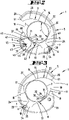
- the shell receptacle 8 or the surface 13 of the first shell part 4 that essentially forms the receptacle extends with reference to a side view according to FIG figure 2 or with reference to a cross-section according to FIG figure 5 along a concave circular arc line viewed from the outside in the direction of the cutting mouth 10 .
- the shell receptacle 9 of the second shell part 5 is also essentially V-shaped with respect to a side view or a cross section transverse to the pivot axis x, having two V-legs 15 and 16 that enclose an angle ⁇ of preferably about 90 degrees to one another , where the V-opening of this shell receptacle 9 faces the shell receptacle 8 of the first shell part 4 running in the shape of a circular arc.
- the cutting mouth 10 results between these shell receptacles 8 and 9.
- the two V-legs 15 and 16 are connected to one another in the area of a V-tip via a circular arc section 17 .
- This arcuate section 17 preferably has a radius r which can correspond to approximately 0.2 to 0.4 times, further approximately 0.25 to 0.3 times the radius r' of the shell receptacle 8 in the form of an arc of a circle.
- the V-legs 15 and 16 which preferably run in a straight line starting from the circular arc section 17 in the side view or in the cross section, can, as also more preferably, extend over approximately the same extent, with the V-leg 15 preferably being in the longitudinal edge 7 close to the axis of the second shell part 5 having the V-shaped shell receptacle 9 .
- the other V-leg 16 is the end, d. H. away from the circular arc section 17, via a curve 23 facing inwards and thus essentially in the direction of the cutting mouth 10.
- This curve 23 can be formed essentially in the form of a section of a circle with reference to the side view or the cross section, more preferably with a radius r ", which can correspond to about 0.5 to 0.75 times, more preferably about 0.6 to 0.7 times the radius r' of the circular shell receptacle 8 of the first shell part 4.
- the geometry of the shell receptacle 9 of the second shell part 5 can also be chosen such that a perpendicular to an angle bisector w of the V-shaped shell receptacle 9 running and the pivot axis x intersects Line u on the one hand intersects the shell receptacle 9 approximately in the transition area from the V-leg 16 into the curvature 23 at point P and on the other hand the V-leg 15 running into the longitudinal edge 7 at a point P'.
- a support section 24 with a triangular cross-section which is delimited on the one hand by an end section of the V-leg 15, with an extension length of about a quarter or a fifth of the total length of the V-leg 16, as well as by the adjoining longitudinal edge 7 and by the geometric line u.
- a plane containing the line u and the pivot axis x is correspondingly penetrated by the area of the shell part 5 that forms the support section 24, as well as by the free end section with the curvature 23.
- the above-described vertical can also have a depression 25 that is essentially triangular in cross section in the first shell part 4 limit which indentation 25 can be adapted in cross-section to the contour of the support section 24 of the second shell part 5.
- the indentation 25 can also offer support for the support section 24, for example to form a limit stop in the inward pivoting direction of the first shell part 4.
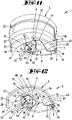
- the ratio of the pivot radii t a and t a ′ relating to the pivot axis x can essentially correspond to the above-described ratio of the lengths a and b of the shell parts 4 and 5 .
- first shorter shell part 4 is formed by individual rib-like projections 21 spaced apart from one another in the direction of the pivot axis x, which projections 21 engage in depressions 22 formed in regions between the ribs 12 of the second shell part 5 .
- the end face 60 of the first shell part 4 pointing in the pivot direction c moves within the relevant outer pivot radius t a and an inner pivot radius t i .
- These pivoting radii t a and t i correspondingly substantially delimit the end face 60 radially on the outside and radially on the inside.
- the radially outer pivoting radius t a of the first shell part 4 is preferably chosen to be smaller than the radially inner pivoting radius t i ' of the second shell part 5 0.5 to 0.9 times, more preferably about 0.7 to 0.8 times the size of the inner pivoting radius t i ' of the second shell part 5 correspond.
- a limit stop in the closed position of the shell parts 4 and 5 can also be achieved in that in the root region of the projections 21 adjacent regions that space the projections 21 from one another come against the end faces 11 of the ribs 12 of the second shell part 5 .
- the outer wall 26 of the first shell part 4 can overlap the contour of the shell receptacle 9 approximately at the above-described point P of the second shell part 5 cut.
- the shell parts 4 and 5 can have a plurality of rib formations 27, preferably spaced apart from one another in the direction of the pivot axis x. These rib formations 27 accordingly extend transversely to the pivot axis x, and according to the representation in FIG. 11 the rib formations 27 can extend across the entire extent of the second, longer shell part 5 transversely to the pivot axis x. Furthermore, these rib formations 27 of the second shell part 5 can continue in the first shell part 4 at least over a partial section with an interruption caused by the gap 28 resulting in the connection area V between the shell parts 4 and 5 .
- the cutting blade 26 held in the first shell part 4 protrudes in particular with its linear blade in the exemplary embodiment shown Cutting edge 29 at least partially beyond the surface 13 of the associated shell receptacle 8 into the cutting mouth 10.
- the circular section shape of the shell receptacle 8 can accordingly be interrupted by the protruding cutting blade 26, with the projecting area 30 of the cutting blade 26 being depicted as an angle in cross section.
- the cutting blade 26 extends in particular in the area of the cutting edge 29 in a cutting plane S directed transversely to the pivot axis x, in which the above-described contours of the shell receptacles 8 and 9 also result.
- the projecting area of the cutting knife 26 can, as preferred, be formed by a short leg 31 and a long leg 32 , with the long leg 32 being able to be given by a section of the cutting edge 29 .
- the length of the long leg 32 can correspond to approximately half the total length of the cutting edge 29 .
- the long leg 32 and the short leg 31 are preferably aligned at a 90-degree angle to one another, with the long leg 32 formed by a section of the cutting edge 29 in particular also having an acute angle ⁇ of approximately 30 to 45 degrees to a tangent T of the circular arc of the shell receptacle 8 may include.
- the cutting edge 29, starting from the surface 13 of the shell receptacle 8 is inclined away from the pivot axis x in the direction of the free radial end 19.
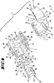
- the cutting blade 26 is more preferably arranged in an exchangeable blade carrier 33 . Preference is given to an essentially end-side arrangement of the cutting blade 26 in relation to the longitudinal extension L in the area of a front side of the blade carrier 33, with the cutting blade 26 being clamped between the block-like blade carrier 33 and a cover plate 34 at the end.
- the mounting of the cutting blade 26 is preferably achieved as a result of a screw connection, with the relevant screw 35 passing through the cover plate 34 and the cutting blade 26 in the area of a bore 36, for threaded engagement in a threaded bore in the blade carrier 33.
- the screw axis is preferably aligned with the pivot axis x .
- the cover plate 34 can have pin-like projections 50 adjacent to a bore 53 for the screw 35, for passing through openings 51 on the blade side and for engaging in cup-like depressions 52 in the blade carrier 30 (compare figures 4 and 15 ).
- the surface of the knife carrier 33 facing the cutting mouth 10 as well as the cover plate 34 is adapted to the circular segment shape of the shell receptacle 8 with reference to a cross section through the cutting device 1, or with reference to a plane running parallel to the cutting plane S, so that the , the shell receptacle 8 forming surface 13 continues in the area of the blade carrier 33 substantially. This results in a surface 37 or 38 curved in the shape of a segment of a circle on the upper side of the knife carrier 33 or the cover plate 34.
- the knife carrier 33 is also arranged in the first shell part 4 in the direction of the pivot axis x so that it can be moved, in particular slidably.
- the arrangement position is also preferably secured by a screw 39 that penetrates the shell part 4 perpendicularly to the direction of displacement f of the blade carrier 33 and is accessible from the outside.
- the receptacle 40 in the blade carrier 33 for the screw 39 extends correspondingly transversely to the direction of displacement f or to the pivot axis x.
- the knife carrier 33 can be guided in the shell part 4 in the manner of rails, for which purpose groove-like guide receptacles 41 and 42 are provided in the shell part 4 and extend in the direction of the pivot axis x.
- These guide receptacles 41 and 42 are preferably provided on both sides with respect to a cross section, but at different heights in a direction perpendicular to the displacement direction f.
- the blade carrier 33 has a guide projection 43 on the side. This engages in an orientation of the knife carrier 33 according to the illustrations in FIG Figures 1 to 8 into the lower guide receptacle 41 spaced farther from the surface 13 of the shell receptacle 8, while a base-side support section 44 with an approximately triangular cross-section is guided in a depression 46 formed on the bottom side of the carrier receptacle 45.
- the cutting knife 26 is preferably arranged essentially in the center of the longitudinal extent L of the shell part 4, with the surface 37 of the knife carrier 33 supplementing the surface 13 of the first shell part 4 forming the shell receptacle 8.
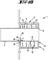
- the blade carrier 33 can essentially be turned around an axis directed in the direction of the screw 39 so that the cutting blade 26 is then arranged close to the edge of the shell part 4 . It results hereafter only a distance to the shell edge 49 depending on the thickness of the cover plate 34 holding the cutting blade 26. There can be a distance d between the bowl edge 49 and the cutting edge 29 of, for example, 2 to 5 mm, further for example about 3 mm (cf figure 10 ). In this constellation, the cutting device 1 can be used in particular to cut sleeves 3, further, for example, so-called drip sleeves, to length.
- the guide projection 43 engages in the other guide seat 42, which is at a smaller distance from the surface 13 of the shell seat 8, while the support section 44 is supported on the tip side in a further depression 47 of the carrier seat 45, which is triangular in cross section.
- the projection of the cutting blade 26, in particular the cutting edge 29, is greater than the central arrangement of the cutting blade 26, with the further surface 38 of the blade carrier 33 supplementing the surface 13 of the shell receptacle 8.
- a dimension e between the transition area of the V-legs 15 and 16 and the intersection point of a bisecting line between the legs 15 and 16 and the surface of the shell receptacle 8 corresponds to approximately 1.3 to 2 times, further about 1.5 times the dimension e in the central and lower arrangement of the cutting blade 26 in relation to the carrier receptacle 45 (cf figure 15 ).
- the surfaces 37 and 38 of the knife carrier 33 extend in cross section or in the side view in a crescent-like or roof-like manner.
- the figures 9 and 10 show the use of the cutting device 1 with a central arrangement of the cutting blade 26 for cutting pipes 2 to length in the course of processing pipes 2 of different diameters.
- the cutting direction g in which the cutting device 1 is rotated around the pipe 2 or the sleeve 3 in the direction of the cutting mouth 10 under the action of external force on the shell parts 4, 5, can be specified on the outside of the cutting device 1 by symbols 48.
- the bolt 18 securing the storage position can be penetrated by the axis body 54 forming the geometric pivot axis x in the area of a slot opening 55 running perpendicularly to the pivot axis x, this preferably in the case of lateral guidance through sections of the second shell part 5 close to the connection area V.
- the bolt 18 is accommodated in a pocket-like, open-edged recess 56 of the second shell part 5 .
- a latching projection 57 that protrudes into this recess 56 in the direction of the latch 18 and can be walked over allows two latching positions of the latch 18 in cooperation with two latching recesses 58 that are spaced apart in the direction of extension of the elongated hole opening 55 .
- a cutting device which is characterized in that the radially outer ends 19, 20 of the shell parts 4, 5 with respect to the pivot axis x can be moved on different radii t a , t a ' , that a radially shorter first shell part 4 up to an overlap to the shell receptacle 9 of the second shell part 5 and that when the shell parts 4, 5 are fully retracted, the radially outer free end 20 of the second shell part 9 is free from overlapping by the first shell part 4 in a pivoting direction c.
- a cutting device which is characterized in that a surface 14 of the second shell part 5 forming the shell receptacle 9 can be pushed through by the radially outer end 19 of the first shell part 4 .
- a cutting device characterized in that the surface 14 of the bowl seat 9 is formed partly as a real surface and partly as an enveloping surface H.
- a cutting device which is characterized in that the penetration in the area of the enveloping surface H can be reached.
- a cutting device which is characterized in that the end faces 11 of inwardly projecting ribs 12 on the second shell part 5 form a surface 14 of the shell receptacle 9 .
- a cutting device which is characterized in that the shell parts 4, 5 have a plurality of spaced rib formations 27 on the outside, which extend transversely to the pivot axis x.
- a cutting device which is characterized in that a rib formation 27 of one shell part 5 continues in alignment in the other shell part 4 with an interruption through the pivot axis x.
- a cutting device which is characterized in that the cutting blade 26 is arranged in an exchangeable blade carrier 33 .
- a cutting device which is characterized in that the knife carrier 33 is arranged in the shell part 4 so that it can be turned.
- a cutting device which is characterized in that the cutting blade 26 is arranged eccentrically with respect to a longitudinal extension L of the cutting device 1 .
- a cutting device which is characterized in that the knife holder 33 is arranged in the shell part 4 so that it can be moved in the direction of the pivot axis x in order to replace the knife holder 33 .
- a cutting device which is characterized in that several guide receptacles 41, 42 are provided for the knife carrier 33, for arranging the knife carrier 33 at different heights in the shell part 4.
- a cutting device which is characterized in that the knife carrier 33 can be fixed in the shell part 4 by means of a screw 39 .
- a cutting device which is characterized in that a receptacle 40 for the screw 39 in the knife carrier 33 extends transversely to a displacement direction f of the knife carrier 33.
- a cutting device characterized in that an opening angle ⁇ of the V-cup seat 9 is between 80 and 100 degrees.
- a cutting device which is characterized in that, with the exception of a cutting blade 26, the shell receptacle 8 of the further shell part 4 is formed in the shape of a segment of a circle.
- a cutting device characterized in that the circular section shape is interrupted by the cutting blade 26 protruding from the shell receptacle 8 and that the protruding portion 30 of the cutting blade 26 is formed in an angle.
- a cutting device which is characterized in that a V-leg 15 of the shell receptacle 9 transitions into an inward-facing curve 23 at the end.
- a cutting device which is characterized in that the curvature 23 is formed in the shape of a segment of a circle.
Landscapes
- Engineering & Computer Science (AREA)
- Mechanical Engineering (AREA)
- Life Sciences & Earth Sciences (AREA)
- Forests & Forestry (AREA)
- Physics & Mathematics (AREA)
- Optics & Photonics (AREA)
- Knives (AREA)
- Sawing (AREA)
- Details Of Cutting Devices (AREA)
Priority Applications (1)
| Application Number | Priority Date | Filing Date | Title |
|---|---|---|---|
| EP24189624.0A EP4424481A3 (fr) | 2021-03-05 | 2022-03-02 | Appareil de coupe permettant de découper des tubes ou des manchons |
Applications Claiming Priority (1)
| Application Number | Priority Date | Filing Date | Title |
|---|---|---|---|
| DE102021105343.9A DE102021105343A1 (de) | 2021-03-05 | 2021-03-05 | Schneidgerät zum Ablängen von Rohren oder Hülsen |
Related Child Applications (2)
| Application Number | Title | Priority Date | Filing Date |
|---|---|---|---|
| EP24189624.0A Division-Into EP4424481A3 (fr) | 2021-03-05 | 2022-03-02 | Appareil de coupe permettant de découper des tubes ou des manchons |
| EP24189624.0A Division EP4424481A3 (fr) | 2021-03-05 | 2022-03-02 | Appareil de coupe permettant de découper des tubes ou des manchons |
Publications (3)
| Publication Number | Publication Date |
|---|---|
| EP4052871A2 true EP4052871A2 (fr) | 2022-09-07 |
| EP4052871A3 EP4052871A3 (fr) | 2022-12-07 |
| EP4052871B1 EP4052871B1 (fr) | 2024-08-28 |
Family
ID=80735590
Family Applications (2)
| Application Number | Title | Priority Date | Filing Date |
|---|---|---|---|
| EP24189624.0A Pending EP4424481A3 (fr) | 2021-03-05 | 2022-03-02 | Appareil de coupe permettant de découper des tubes ou des manchons |
| EP22159651.3A Active EP4052871B1 (fr) | 2021-03-05 | 2022-03-02 | Appareil de coupe permettant de découper des tubes ou des manchons |
Family Applications Before (1)
| Application Number | Title | Priority Date | Filing Date |
|---|---|---|---|
| EP24189624.0A Pending EP4424481A3 (fr) | 2021-03-05 | 2022-03-02 | Appareil de coupe permettant de découper des tubes ou des manchons |
Country Status (6)
| Country | Link |
|---|---|
| EP (2) | EP4424481A3 (fr) |
| CN (1) | CN115007945A (fr) |
| DE (2) | DE102021105343A1 (fr) |
| ES (1) | ES2989037T3 (fr) |
| PL (1) | PL4052871T3 (fr) |
| TW (1) | TWI909007B (fr) |
Cited By (1)
| Publication number | Priority date | Publication date | Assignee | Title |
|---|---|---|---|---|
| CN117862915A (zh) * | 2024-02-22 | 2024-04-12 | 江西东驰新能源产业有限公司 | 钠电池生产用定位设备及定位方法 |
Families Citing this family (1)
| Publication number | Priority date | Publication date | Assignee | Title |
|---|---|---|---|---|
| DE102022003899A1 (de) | 2022-10-21 | 2024-05-02 | Ralf Plonski | Schneidegerät für Kartuschen (Silikon, Acryl usw.) damit diese in Verbindung mit neuem Auspressvorsatz immer wieder auch nach Teileintrocknung/Erhärten entleert werden können so erlangt man auch völlig Restenleerte Kartuschen/Recycling Materalinhalt kann völlig verarbeitet werden |
Citations (2)
| Publication number | Priority date | Publication date | Assignee | Title |
|---|---|---|---|---|
| DE202014101596U1 (de) | 2014-04-04 | 2014-04-29 | Klaus Knipping Gmbh | Vorrichtung zum Abisolieren von Koaxialkabeln |
| DE102017129725A1 (de) | 2017-12-13 | 2019-06-13 | Knipex-Werk C. Gustav Putsch Kg | Schneidgerät zum Ablängen von Wellrohren sowie Führungsvorsprünge in einem solchen Schneidgerät |
Family Cites Families (15)
| Publication number | Priority date | Publication date | Assignee | Title |
|---|---|---|---|---|
| DE2849733A1 (de) * | 1978-11-16 | 1980-05-29 | Horst Hartmann | Schneidgeraet zum zerkleinern von nahrungsmitteln wie fleisch, zwiebel, gemuese o.dgl. |
| CH662082A5 (en) * | 1984-02-15 | 1987-09-15 | Fischer Ag Georg | Cutting device for cutting to length a protective pipe surrounding a conduit |
| ES295257Y (es) | 1986-06-25 | 1987-08-16 | Diaz De Guerenu Aguirrebeitia Pablo | Aparato perfeccionado, para el pelado de cables electricos y similares |
| US5956853A (en) * | 1997-06-10 | 1999-09-28 | Watamura; Abe | Pipe cutting tool for plastic pipe |
| DE29810244U1 (de) * | 1998-06-10 | 1999-05-20 | Mehnert, Erich, 66399 Mandelbachtal | Kunststoffrohrschneider für Normrohrgrößen |
| US6427331B1 (en) | 2000-11-28 | 2002-08-06 | Capewell Components Company, Llc | Slitting and shaving tool for messengered cable |
| US20090158597A1 (en) | 2007-12-20 | 2009-06-25 | Tyco Healthcare Group Lp | Medical Tubing Cutter |
| JP5366656B2 (ja) * | 2009-05-22 | 2013-12-11 | 株式会社松阪鉄工所 | パイプ切断具 |
| US9089958B2 (en) * | 2011-07-01 | 2015-07-28 | Mil3 Inc. | Multi-functional tool for flexible pipe and related methods |
| DE102015011394B4 (de) * | 2015-08-31 | 2018-11-15 | Sks Welding Systems Gmbh | Vorrichtung und Verfahren zum Schneiden von Kunststoffrohren |
| CN110505950A (zh) * | 2017-04-20 | 2019-11-26 | 默克专利股份公司 | 用于无菌测试的人体工程学用后即丢切割工具 |
| DE102017109629A1 (de) | 2017-05-04 | 2018-11-08 | Siang Syuan Fu Enterprise Co., Ltd. | Schneidgerät |
| NL1042524B1 (en) | 2017-08-31 | 2019-03-11 | Wavin Bv | Handheld pipe cutter comprising a securer and a method of cutting a pipe |
| GB2583554A (en) * | 2019-04-30 | 2020-11-04 | Monument Tools Ltd | Pipe cutter |
| CN111014806B (zh) * | 2020-01-03 | 2025-03-18 | 深圳市燃气集团股份有限公司 | 一种自动切管装置 |
-
2021
- 2021-03-05 DE DE102021105343.9A patent/DE102021105343A1/de active Pending
-
2022
- 2022-03-02 EP EP24189624.0A patent/EP4424481A3/fr active Pending
- 2022-03-02 TW TW111107446A patent/TWI909007B/zh active
- 2022-03-02 DE DE202022105079.1U patent/DE202022105079U1/de active Active
- 2022-03-02 ES ES22159651T patent/ES2989037T3/es active Active
- 2022-03-02 PL PL22159651.3T patent/PL4052871T3/pl unknown
- 2022-03-02 CN CN202210197829.XA patent/CN115007945A/zh active Pending
- 2022-03-02 EP EP22159651.3A patent/EP4052871B1/fr active Active
Patent Citations (2)
| Publication number | Priority date | Publication date | Assignee | Title |
|---|---|---|---|---|
| DE202014101596U1 (de) | 2014-04-04 | 2014-04-29 | Klaus Knipping Gmbh | Vorrichtung zum Abisolieren von Koaxialkabeln |
| DE102017129725A1 (de) | 2017-12-13 | 2019-06-13 | Knipex-Werk C. Gustav Putsch Kg | Schneidgerät zum Ablängen von Wellrohren sowie Führungsvorsprünge in einem solchen Schneidgerät |
Cited By (1)
| Publication number | Priority date | Publication date | Assignee | Title |
|---|---|---|---|---|
| CN117862915A (zh) * | 2024-02-22 | 2024-04-12 | 江西东驰新能源产业有限公司 | 钠电池生产用定位设备及定位方法 |
Also Published As
| Publication number | Publication date |
|---|---|
| DE202022105079U1 (de) | 2022-09-19 |
| CN115007945A (zh) | 2022-09-06 |
| PL4052871T3 (pl) | 2025-01-13 |
| ES2989037T3 (es) | 2024-11-25 |
| EP4052871A3 (fr) | 2022-12-07 |
| EP4052871B1 (fr) | 2024-08-28 |
| EP4424481A3 (fr) | 2024-12-11 |
| TWI909007B (zh) | 2025-12-21 |
| TW202235240A (zh) | 2022-09-16 |
| EP4424481A2 (fr) | 2024-09-04 |
| DE102021105343A1 (de) | 2022-09-08 |
Similar Documents
| Publication | Publication Date | Title |
|---|---|---|
| EP2664426B1 (fr) | Protection de chaîne et système de scie à chaîne | |
| EP0250726A2 (fr) | Appareil pour découper des éléments essentiellement cylindriques | |
| EP3138674B1 (fr) | Dispositif de coupe en onglet | |
| EP3655189A2 (fr) | Dispositif de travail pour couper une piece | |
| DE10040612A1 (de) | Schneidplatte für drehende Werkzeuge | |
| EP3326251B1 (fr) | Outil de dénudage | |
| EP4052871B1 (fr) | Appareil de coupe permettant de découper des tubes ou des manchons | |
| EP1754561B1 (fr) | Dispositif de coupe | |
| EP3784438A1 (fr) | Pince | |
| WO2005100748A1 (fr) | Dispositif pour maintenir un trepan a tige | |
| EP2512744B1 (fr) | Pince | |
| EP4104263B1 (fr) | Outil de coupe de type pince | |
| EP0305414B1 (fr) | Couteau | |
| EP3723928B1 (fr) | Dispositif de coupe pour couper des tubes ondulés à longueur et guidage des saillies dans un tel dispositif de coupe | |
| EP1816716B1 (fr) | Outil à dénuder | |
| WO1999012680A1 (fr) | Outil d'usinage | |
| EP1295688B1 (fr) | Dispositif ainsi que procédé pour couper des tuyaux | |
| EP3932253B1 (fr) | Brosse destinée à l'utilisation avec une motofaucheuse | |
| EP3702100B1 (fr) | Dispositif de butée | |
| EP2275282A1 (fr) | Appareil de décollement de tapisserie | |
| DE102024102186A1 (de) | Entgratwerkzeug für rohrförmige Werkstücke | |
| DE102016117972A1 (de) | Fräswerkzeug, Schneidplattenhalter und Schneidplatte | |
| EP0442004B1 (fr) | Couteau à lames interchangeables | |
| DE9102122U1 (de) | Energieführungskette | |
| DE102024206798A1 (de) | Auswechselbarer Messerträger |
Legal Events
| Date | Code | Title | Description |
|---|---|---|---|
| REG | Reference to a national code |
Ref country code: DE Ref legal event code: R138 Ref document number: 202022105079 Country of ref document: DE Free format text: GERMAN DOCUMENT NUMBER IS 502022001533 |
|
| PUAI | Public reference made under article 153(3) epc to a published international application that has entered the european phase |
Free format text: ORIGINAL CODE: 0009012 |
|
| STAA | Information on the status of an ep patent application or granted ep patent |
Free format text: STATUS: THE APPLICATION HAS BEEN PUBLISHED |
|
| AK | Designated contracting states |
Kind code of ref document: A2 Designated state(s): AL AT BE BG CH CY CZ DE DK EE ES FI FR GB GR HR HU IE IS IT LI LT LU LV MC MK MT NL NO PL PT RO RS SE SI SK SM TR |
|
| PUAL | Search report despatched |
Free format text: ORIGINAL CODE: 0009013 |
|
| AK | Designated contracting states |
Kind code of ref document: A3 Designated state(s): AL AT BE BG CH CY CZ DE DK EE ES FI FR GB GR HR HU IE IS IT LI LT LU LV MC MK MT NL NO PL PT RO RS SE SI SK SM TR |
|
| RIC1 | Information provided on ipc code assigned before grant |
Ipc: B26D 5/10 20060101ALI20221102BHEP Ipc: B23D 21/06 20060101ALI20221102BHEP Ipc: B26D 7/26 20060101ALI20221102BHEP Ipc: B26D 3/16 20060101AFI20221102BHEP |
|
| STAA | Information on the status of an ep patent application or granted ep patent |
Free format text: STATUS: REQUEST FOR EXAMINATION WAS MADE |
|
| 17P | Request for examination filed |
Effective date: 20230330 |
|
| RBV | Designated contracting states (corrected) |
Designated state(s): AL AT BE BG CH CY CZ DE DK EE ES FI FR GB GR HR HU IE IS IT LI LT LU LV MC MK MT NL NO PL PT RO RS SE SI SK SM TR |
|
| GRAP | Despatch of communication of intention to grant a patent |
Free format text: ORIGINAL CODE: EPIDOSNIGR1 |
|
| STAA | Information on the status of an ep patent application or granted ep patent |
Free format text: STATUS: GRANT OF PATENT IS INTENDED |
|
| INTG | Intention to grant announced |
Effective date: 20240425 |
|
| GRAS | Grant fee paid |
Free format text: ORIGINAL CODE: EPIDOSNIGR3 |
|
| GRAA | (expected) grant |
Free format text: ORIGINAL CODE: 0009210 |
|
| STAA | Information on the status of an ep patent application or granted ep patent |
Free format text: STATUS: THE PATENT HAS BEEN GRANTED |
|
| AK | Designated contracting states |
Kind code of ref document: B1 Designated state(s): AL AT BE BG CH CY CZ DE DK EE ES FI FR GB GR HR HU IE IS IT LI LT LU LV MC MK MT NL NO PL PT RO RS SE SI SK SM TR |
|
| REG | Reference to a national code |
Ref country code: CH Ref legal event code: EP |
|
| REG | Reference to a national code |
Ref country code: DE Ref legal event code: R096 Ref document number: 502022001533 Country of ref document: DE |
|
| REG | Reference to a national code |
Ref country code: IE Ref legal event code: FG4D Free format text: LANGUAGE OF EP DOCUMENT: GERMAN |
|
| REG | Reference to a national code |
Ref country code: ES Ref legal event code: FG2A Ref document number: 2989037 Country of ref document: ES Kind code of ref document: T3 Effective date: 20241125 |
|
| REG | Reference to a national code |
Ref country code: LT Ref legal event code: MG9D |
|
| PG25 | Lapsed in a contracting state [announced via postgrant information from national office to epo] |
Ref country code: NO Free format text: LAPSE BECAUSE OF FAILURE TO SUBMIT A TRANSLATION OF THE DESCRIPTION OR TO PAY THE FEE WITHIN THE PRESCRIBED TIME-LIMIT Effective date: 20241128 |
|
| PG25 | Lapsed in a contracting state [announced via postgrant information from national office to epo] |
Ref country code: FI Free format text: LAPSE BECAUSE OF FAILURE TO SUBMIT A TRANSLATION OF THE DESCRIPTION OR TO PAY THE FEE WITHIN THE PRESCRIBED TIME-LIMIT Effective date: 20240828 Ref country code: NL Free format text: LAPSE BECAUSE OF FAILURE TO SUBMIT A TRANSLATION OF THE DESCRIPTION OR TO PAY THE FEE WITHIN THE PRESCRIBED TIME-LIMIT Effective date: 20240828 Ref country code: PT Free format text: LAPSE BECAUSE OF FAILURE TO SUBMIT A TRANSLATION OF THE DESCRIPTION OR TO PAY THE FEE WITHIN THE PRESCRIBED TIME-LIMIT Effective date: 20241230 Ref country code: GR Free format text: LAPSE BECAUSE OF FAILURE TO SUBMIT A TRANSLATION OF THE DESCRIPTION OR TO PAY THE FEE WITHIN THE PRESCRIBED TIME-LIMIT Effective date: 20241129 |
|
| PG25 | Lapsed in a contracting state [announced via postgrant information from national office to epo] |
Ref country code: BG Free format text: LAPSE BECAUSE OF FAILURE TO SUBMIT A TRANSLATION OF THE DESCRIPTION OR TO PAY THE FEE WITHIN THE PRESCRIBED TIME-LIMIT Effective date: 20240828 |
|
| PG25 | Lapsed in a contracting state [announced via postgrant information from national office to epo] |
Ref country code: LV Free format text: LAPSE BECAUSE OF FAILURE TO SUBMIT A TRANSLATION OF THE DESCRIPTION OR TO PAY THE FEE WITHIN THE PRESCRIBED TIME-LIMIT Effective date: 20240828 |
|
| REG | Reference to a national code |
Ref country code: NL Ref legal event code: MP Effective date: 20240828 |
|
| PG25 | Lapsed in a contracting state [announced via postgrant information from national office to epo] |
Ref country code: IS Free format text: LAPSE BECAUSE OF FAILURE TO SUBMIT A TRANSLATION OF THE DESCRIPTION OR TO PAY THE FEE WITHIN THE PRESCRIBED TIME-LIMIT Effective date: 20241228 |
|
| PG25 | Lapsed in a contracting state [announced via postgrant information from national office to epo] |
Ref country code: HR Free format text: LAPSE BECAUSE OF FAILURE TO SUBMIT A TRANSLATION OF THE DESCRIPTION OR TO PAY THE FEE WITHIN THE PRESCRIBED TIME-LIMIT Effective date: 20240828 |
|
| PG25 | Lapsed in a contracting state [announced via postgrant information from national office to epo] |
Ref country code: RS Free format text: LAPSE BECAUSE OF FAILURE TO SUBMIT A TRANSLATION OF THE DESCRIPTION OR TO PAY THE FEE WITHIN THE PRESCRIBED TIME-LIMIT Effective date: 20241128 |
|
| PG25 | Lapsed in a contracting state [announced via postgrant information from national office to epo] |
Ref country code: RS Free format text: LAPSE BECAUSE OF FAILURE TO SUBMIT A TRANSLATION OF THE DESCRIPTION OR TO PAY THE FEE WITHIN THE PRESCRIBED TIME-LIMIT Effective date: 20241128 Ref country code: PT Free format text: LAPSE BECAUSE OF FAILURE TO SUBMIT A TRANSLATION OF THE DESCRIPTION OR TO PAY THE FEE WITHIN THE PRESCRIBED TIME-LIMIT Effective date: 20241230 Ref country code: NO Free format text: LAPSE BECAUSE OF FAILURE TO SUBMIT A TRANSLATION OF THE DESCRIPTION OR TO PAY THE FEE WITHIN THE PRESCRIBED TIME-LIMIT Effective date: 20241128 Ref country code: NL Free format text: LAPSE BECAUSE OF FAILURE TO SUBMIT A TRANSLATION OF THE DESCRIPTION OR TO PAY THE FEE WITHIN THE PRESCRIBED TIME-LIMIT Effective date: 20240828 Ref country code: LV Free format text: LAPSE BECAUSE OF FAILURE TO SUBMIT A TRANSLATION OF THE DESCRIPTION OR TO PAY THE FEE WITHIN THE PRESCRIBED TIME-LIMIT Effective date: 20240828 Ref country code: IS Free format text: LAPSE BECAUSE OF FAILURE TO SUBMIT A TRANSLATION OF THE DESCRIPTION OR TO PAY THE FEE WITHIN THE PRESCRIBED TIME-LIMIT Effective date: 20241228 Ref country code: HR Free format text: LAPSE BECAUSE OF FAILURE TO SUBMIT A TRANSLATION OF THE DESCRIPTION OR TO PAY THE FEE WITHIN THE PRESCRIBED TIME-LIMIT Effective date: 20240828 Ref country code: GR Free format text: LAPSE BECAUSE OF FAILURE TO SUBMIT A TRANSLATION OF THE DESCRIPTION OR TO PAY THE FEE WITHIN THE PRESCRIBED TIME-LIMIT Effective date: 20241129 Ref country code: FI Free format text: LAPSE BECAUSE OF FAILURE TO SUBMIT A TRANSLATION OF THE DESCRIPTION OR TO PAY THE FEE WITHIN THE PRESCRIBED TIME-LIMIT Effective date: 20240828 Ref country code: BG Free format text: LAPSE BECAUSE OF FAILURE TO SUBMIT A TRANSLATION OF THE DESCRIPTION OR TO PAY THE FEE WITHIN THE PRESCRIBED TIME-LIMIT Effective date: 20240828 |
|
| PGFP | Annual fee paid to national office [announced via postgrant information from national office to epo] |
Ref country code: DE Payment date: 20250319 Year of fee payment: 4 |
|
| PG25 | Lapsed in a contracting state [announced via postgrant information from national office to epo] |
Ref country code: RO Free format text: LAPSE BECAUSE OF FAILURE TO SUBMIT A TRANSLATION OF THE DESCRIPTION OR TO PAY THE FEE WITHIN THE PRESCRIBED TIME-LIMIT Effective date: 20240828 Ref country code: DK Free format text: LAPSE BECAUSE OF FAILURE TO SUBMIT A TRANSLATION OF THE DESCRIPTION OR TO PAY THE FEE WITHIN THE PRESCRIBED TIME-LIMIT Effective date: 20240828 Ref country code: SM Free format text: LAPSE BECAUSE OF FAILURE TO SUBMIT A TRANSLATION OF THE DESCRIPTION OR TO PAY THE FEE WITHIN THE PRESCRIBED TIME-LIMIT Effective date: 20240828 |
|
| PG25 | Lapsed in a contracting state [announced via postgrant information from national office to epo] |
Ref country code: EE Free format text: LAPSE BECAUSE OF FAILURE TO SUBMIT A TRANSLATION OF THE DESCRIPTION OR TO PAY THE FEE WITHIN THE PRESCRIBED TIME-LIMIT Effective date: 20240828 |
|
| PG25 | Lapsed in a contracting state [announced via postgrant information from national office to epo] |
Ref country code: CZ Free format text: LAPSE BECAUSE OF FAILURE TO SUBMIT A TRANSLATION OF THE DESCRIPTION OR TO PAY THE FEE WITHIN THE PRESCRIBED TIME-LIMIT Effective date: 20240828 |
|
| PG25 | Lapsed in a contracting state [announced via postgrant information from national office to epo] |
Ref country code: SK Free format text: LAPSE BECAUSE OF FAILURE TO SUBMIT A TRANSLATION OF THE DESCRIPTION OR TO PAY THE FEE WITHIN THE PRESCRIBED TIME-LIMIT Effective date: 20240828 |
|
| REG | Reference to a national code |
Ref country code: DE Ref legal event code: R097 Ref document number: 502022001533 Country of ref document: DE |
|
| PLBE | No opposition filed within time limit |
Free format text: ORIGINAL CODE: 0009261 |
|
| STAA | Information on the status of an ep patent application or granted ep patent |
Free format text: STATUS: NO OPPOSITION FILED WITHIN TIME LIMIT |
|
| PGFP | Annual fee paid to national office [announced via postgrant information from national office to epo] |
Ref country code: ES Payment date: 20250416 Year of fee payment: 4 |
|
| 26N | No opposition filed |
Effective date: 20250530 |
|
| PG25 | Lapsed in a contracting state [announced via postgrant information from national office to epo] |
Ref country code: SE Free format text: LAPSE BECAUSE OF FAILURE TO SUBMIT A TRANSLATION OF THE DESCRIPTION OR TO PAY THE FEE WITHIN THE PRESCRIBED TIME-LIMIT Effective date: 20240828 |
|
| PG25 | Lapsed in a contracting state [announced via postgrant information from national office to epo] |
Ref country code: MC Free format text: LAPSE BECAUSE OF FAILURE TO SUBMIT A TRANSLATION OF THE DESCRIPTION OR TO PAY THE FEE WITHIN THE PRESCRIBED TIME-LIMIT Effective date: 20240828 |
|
| REG | Reference to a national code |
Ref country code: CH Ref legal event code: H13 Free format text: ST27 STATUS EVENT CODE: U-0-0-H10-H13 (AS PROVIDED BY THE NATIONAL OFFICE) Effective date: 20251023 |
|
| PG25 | Lapsed in a contracting state [announced via postgrant information from national office to epo] |
Ref country code: LU Free format text: LAPSE BECAUSE OF NON-PAYMENT OF DUE FEES Effective date: 20250302 |
|
| REG | Reference to a national code |
Ref country code: BE Ref legal event code: MM Effective date: 20250331 |
|
| PG25 | Lapsed in a contracting state [announced via postgrant information from national office to epo] |
Ref country code: BE Free format text: LAPSE BECAUSE OF NON-PAYMENT OF DUE FEES Effective date: 20250331 |
|
| PG25 | Lapsed in a contracting state [announced via postgrant information from national office to epo] |
Ref country code: CH Free format text: LAPSE BECAUSE OF NON-PAYMENT OF DUE FEES Effective date: 20250331 |
|
| PG25 | Lapsed in a contracting state [announced via postgrant information from national office to epo] |
Ref country code: IE Free format text: LAPSE BECAUSE OF NON-PAYMENT OF DUE FEES Effective date: 20250302 |
|
| PGFP | Annual fee paid to national office [announced via postgrant information from national office to epo] |
Ref country code: GB Payment date: 20260309 Year of fee payment: 5 |
|
| PGFP | Annual fee paid to national office [announced via postgrant information from national office to epo] |
Ref country code: AT Payment date: 20260301 Year of fee payment: 5 |
|
| PGFP | Annual fee paid to national office [announced via postgrant information from national office to epo] |
Ref country code: IT Payment date: 20260324 Year of fee payment: 5 |
|
| PGFP | Annual fee paid to national office [announced via postgrant information from national office to epo] |
Ref country code: FR Payment date: 20260309 Year of fee payment: 5 |
|
| PGFP | Annual fee paid to national office [announced via postgrant information from national office to epo] |
Ref country code: PL Payment date: 20260226 Year of fee payment: 5 |