EP3326251B1 - Outil de dénudage - Google Patents
Outil de dénudage Download PDFInfo
- Publication number
- EP3326251B1 EP3326251B1 EP16738708.3A EP16738708A EP3326251B1 EP 3326251 B1 EP3326251 B1 EP 3326251B1 EP 16738708 A EP16738708 A EP 16738708A EP 3326251 B1 EP3326251 B1 EP 3326251B1
- Authority
- EP
- European Patent Office
- Prior art keywords
- hollow body
- stripping tool
- cable
- shell
- shells
- Prior art date
- Legal status (The legal status is an assumption and is not a legal conclusion. Google has not performed a legal analysis and makes no representation as to the accuracy of the status listed.)
- Active
Links
Images


Classifications
-
- H—ELECTRICITY
- H02—GENERATION; CONVERSION OR DISTRIBUTION OF ELECTRIC POWER
- H02G—INSTALLATION OF ELECTRIC CABLES OR LINES, OR OF COMBINED OPTICAL AND ELECTRIC CABLES OR LINES
- H02G1/00—Methods or apparatus specially adapted for installing, maintaining, repairing or dismantling electric cables or lines
- H02G1/12—Methods or apparatus specially adapted for installing, maintaining, repairing or dismantling electric cables or lines for removing insulation or armouring from cables, e.g. from the end thereof
- H02G1/1202—Methods or apparatus specially adapted for installing, maintaining, repairing or dismantling electric cables or lines for removing insulation or armouring from cables, e.g. from the end thereof by cutting and withdrawing insulation
- H02G1/1204—Hand-held tools
- H02G1/1207—Hand-held tools the cutting element not rotating about the wire or cable
- H02G1/1209—Hand-held tools the cutting element not rotating about the wire or cable making a transverse cut
- H02G1/1212—Hand-held tools the cutting element not rotating about the wire or cable making a transverse cut using wire or cable clamping means
Definitions
- the invention relates to a stripping tool for removing an outer sheath and / or a wire insulation of an electrical single or multi-core cable, the stripping tool having hollow body partial shells connected to one another by means of a common pivot axis, which are pivotable towards one another to form a hollow body that at least partially accommodates a cable, wherein the hollow body part shells have at least one cutting element.
- the publication WO 2005/025023 A1 discloses, for example, a stripping tool which can be used both for removing an outer jacket of a multi-core cable and for wire insulation of a single cable.
- the stripping tool consists of two pivotable half shells connected to a shell edge, which have several cutting elements transverse to the longitudinal direction of the half shells.
- the cable is inserted through an opening in a cutting element.
- the stripping tool is gripped in the circumferential direction, the hand of a user encompassing almost the entire stripping tool and the thumb and index finger compressing gripping surfaces arranged in the region of the end face.
- the stripping tool has at least two hollow body partial areas arranged at an angle between approximately 90 ° and 170 °, in particular between 110 ° and 150 °, at least one first hollow body partial area having two hollow body partial shells which can be pivoted relative to one another, at least of which a hollow body part shell can be pivoted without moving a second hollow body part region.
- a first hollow body part region and a second hollow body part region are now arranged at an obtuse angle between 90 ° and 170 ° to one another, as a result of which an angled shape of the Stripping tool results.
- This angled shape enables ergonomic use by the user, so that a tensile force of at least the same magnitude can be applied to a cable without simultaneously putting greater strain on the forearm and / or the hand of the user.
- at least a first hollow body partial area has a cutting element for removing the sheath or the wire insulation, while a second partial area serves as a handle for guiding the stripping tool.
- the two hollow body partial regions particularly advantageously form a pistol-like shape of the stripping tool.
- the pistol-like shape corresponds to the natural posture of one Wrist while applying traction. This prevents excessive stress on the wrist.
- first hollow body part region has two hollow body part shells which can be pivoted relative to one another about a pivot axis
- second hollow body part region is an immovable handle part and thus has no pivotable hollow body part shells.
- the two hollow body part regions have hollow body part shells which can be pivoted relative to one another, that is to say each of the hollow body part regions has a pivot axis.
- each of the hollow body sections can be used both for stripping and as a handle part.
- two hollow body part regions each have two pivotable hollow body part shells, one possible hollow body part region being designed to receive a cable with a first diameter, and a second hollow body part region being designed to receive a cable with a second diameter differs from the first diameter.
- the stripping tool is optimized at least for stripping two cables of different diameters.
- a cable with a larger diameter such as a multi-core round and moisture-proof cable (for example NYM cable) with a diameter of 8 mm to 13 mm, can be stripped in the first hollow part area, while in the second hollow part area a coax cable and / or Data cables with a diameter of 4.5 mm to 10 mm can be stripped.
- the stripping tool have at least two pivot axes, which are arranged on the one hand on a common first hollow part shell and on the other hand on separate second hollow part shells.
- the stripping tool thus has an angled first hollow body part shell which carries two or more pivot axes which are arranged at an angle to one another which corresponds to the angle between the hollow body part regions.
- a separate second hollow body part shell is arranged on each of these pivot axes and can be pivoted independently of a movement of the other second hollow body part shells.
- the first and second pivot axes arranged on separate second hollow body partial shells can either be arranged on the same shell edge of the hollow body or the first hollow body partial shell, on opposite shell edges or also offset by an angular range between 0 ° and 180 ° (in the circumferential direction).
- the hollow body always has the cable, for example, from the left-hand side between each time the user attacks one of the hollow-body partial regions Hollow body part shells must lead.
- the hollow body partial shells of a hollow body region of the stripping tool can, as is also preferred, be locked in a closed position. This can apply to both second hollow body part shells, alternatively, as also preferred, only for one of the two second hollow body part shells.
- the possible interlocking further simplifies the handling of the stripping tool.
- the locking can relate to the hollow body area used for stripping or stripping. The locking can also prove to be favorable in the region of the hollow body section that can be used as a handle.
- the stripping tool can preferably be used both in a locked and in an unlocked position.
- the hollow body part shells can be pivotable by means of an axle body extending in the longitudinal direction of the hollow body part shell.
- This can be an axle body separate from the hollow body part shells that interact with one another, for example an inserted metal axle.
- Both second hollow body part shells are preferably pivotally connected to the first, angled hollow body part shell via such an axle body.
- the axle body can push through a locking part.
- a locking part can be secured fixing serve a second hollow part shell.
- the axle body passing through the locking part can moreover serve the preferably captive fastening of the locking part to one of the hollow body part shells, as well as a possible guidance of the locking part when the locking part is displaced from a locking position into an unlocking position and vice versa.
- the locking part can be moved transversely to the longitudinal direction of the axle body into a locking and unlocking position. This also results in favorable handling, for example a thumb-actuated handling of the locking part in order to shift it from one end position to the other. It can, at least approximately, result in a displacement direction of the locking part that is tangential in cross section with respect to one of the hollow body part shells.
- At least the locking position is locked.
- such a latching occurs both in the locking position and in the unlocking position, which latching can also take place on the same hollow body part shell. In one possible embodiment, this is the first hollow part shell.
- the latching is preferably one which can be canceled by the user simply by introducing a pushing force acting on the locking part, furthermore, for example, due to the overrun of a provided latching projection.
- a first hollow body part region has gripping tabs projecting beyond a peripheral surface for pressing together the hollow body part shells forming the hollow body by means of a thumb and an index finger of a hand, and a second Hollow body part area has a grip surface for simultaneous application of a palm of the hand.
- the attack tabs of the first hollow body part area are gripped and pressed together while a cable is being stripped, while the second hollow body part area is guided through essentially the ball of the hand.
- both the first hollow body part area and the second hollow body part area have grip tabs, so that both hollow body part areas can be used equally for stripping.
- the two engagement tabs be arranged perpendicular to the plane spanned by the two hollow body partial areas. This corresponds to a natural posture of a user's hand while stripping a cable.
- the hollow body formed by the two hollow body partial shells can have a cone, at least with respect to an end region, which widens in the direction of a gripping surface of the stripping tool.
- the stripping tool thus has a conical outer contour on one or both end regions, which serves for better accessibility of the insulating tool in narrow cable junction boxes, electrical boxes or the like. This is particularly advantageous where several cables are close together. To strip one of several cables lying close together, the cable to be stripped is spread apart from the other cables, creating an angle between the cables. The conical end area of the stripping tool is pushed as deep as possible into this angular area, until the conical circumferential surface is pushed as far as possible to the apex.
- the cutting element arranged within the hollow body can advantageously be arranged within the conical end region.
- a circumferential surface of the cone has an angle of approximately 30 ° to 60 ° to an end surface of the end region. This corresponds to the usual spreading apart of a cable to be stripped from several cables lying next to one another.
- the stripping tool can therefore be used optimally.
- the cone be designed starting from an end face of the end region over a length of 5 mm to 20 mm. This provides a sufficiently large outer surface of the stripping tool for spreading a cable, while - in the sense of a handy tool - the smallest possible diameter of the stripping tool is maintained at the same time.
- the hollow body which is at least designed to partially accommodate a cable and has hollow body partial shells to be pivoted toward one another, has an indentation on a shell edge, on which the hollow body partial shells can be pivoted toward one another, for indenting a cable into the hollow body, which indentation in particular has an opening angle ⁇ 180 °.
- This configuration makes it possible to press on the stripping tool with a cable, so that it is not necessary to have a hand for pivoting a hollow part shell to use.
- a cable to be inserted into the hollow body is pressed against the inclined surfaces of the indentation, as a result of which the two hollow body part shells can be separated from one another so that the cable can be inserted.
- the indentation has an opening angle of less than 180 °, so that the indentation does not form a flat surface, but rather the edge areas of the indentation (similar to an overhang) reach over the cable inserted therein. This creates an area of attack on which the cable can engage and the stripping tool can open.
- the user can hold the stripping tool in a first hand on a gripping surface of, for example, a second hollow body part area and press a cable with a second hand against the indentation formed on a first hollow body part area.
- the indentation is also advantageously located in the vicinity of an end region of the stripping tool, in particular an end region which has an opening for gripping through a cable.
- the indentation is particularly advantageously located in an area whose outer contour has a cone that widens in the direction of a gripping surface of the stripping tool.
- the stripping tool is thus particularly easy to reveal by means of the pressure of a cable against the indentation.
- the indentation can also be formed on projecting attack tabs.
- the opening angle of the indentation corresponds to an opening width of 1 mm to 20 mm, in particular corresponds to a diameter of a cable to be accommodated in the hollow body.
- the indentation is thus large enough that even a multi-core cable, such as an NYM cable, can grip an edge of the indentation to open the stripping tool.
- the circumferential section of the indentation be approximately one diameter in diameter Corresponds to the hollow body to be introduced cable, so that slipping of the cable from the stripping tool is reliably prevented.
- the indentation particularly advantageously has an opening angle of 150 ° or less.
- a spring is assigned to the pivot axis, by means of the restoring force of which the hollow body partial shells can be pivoted towards one another to form a hollow body or can be pivoted away from one another to open the hollow body.
- the stripping tool that is to say to insert a cable between the hollow body part shells
- the restoring force of the spring should be such that it is easily possible to open the hollow body part shell by means of a cable engaging the indentation.
- the restoring force swivels the hollow body part shell back into the closed position.
- the cable is already held securely between the hollow body shell parts without the user having to do anything.
- the user then only has to press together the two hollow body part shells, advantageously attack tabs formed on the corresponding hollow body part region.
- the hollow body partial shells can be pivoted away from one another by means of the restoring force of the spring for opening the hollow body, that is to say the restoring force works in the direction of the swung-open position of the hollow body.
- a stripping tool has a first hollow body part region with a spring, the restoring force of which is directed in a closing direction of the hollow body, a second hollow body part region having a spring, the restoring force of which is directed in the opening direction of the hollow body.
- the hollow body part shells on a shell edge on which the hollow body part shells can be pivoted toward one another, have cutting elements arranged next to one another in the direction of the shell edge, the cutting elements being assigned a guide link which has at least one web formed laterally to form a cutting element for aligning a cutting element Has cable on a cutting element, wherein in the case of several webs these are formed in the direction of the shell edge on opposite sides of two cutting elements, in particular two cutting elements lying next to each other.
- the stripping tool is advantageously designed to remove both an outer jacket from a multi-core cable and a core insulation of a single-core cable. While an outer sheath is advantageously removed, for example, via an end face of the stripping tool, a core insulation can be removed, for example, in a direction perpendicular thereto, that is to say on a shell edge of the hollow body.
- the cutting elements are arranged on the shell edge which is essentially opposite the pivot axis and on which the hollow body partial shells can be connected.
- Each hollow part shell carries a cutting element, which corresponds to a cutting element of the opposite hollow body part shell.
- the two hollow body part shells are pivoted away from one another, so that the opposite cutting elements are separated from one another and a cable can be placed between a pair of cutting elements.
- adjacent cutting elements are usually arranged directly next to one another in a direction parallel to the pivot axis, it being possible for these to be arranged next to one another with increasing size.
- the increasing size of the cutting elements corresponds to different cable diameters.
- the size difference between the cutting elements is often not easy to recognize, so that in the case of a large number, for example ten, cutting elements arranged next to one another, a user cannot immediately recognize which cutting element is the most suitable or which cutting element he has used in a previous stripping process.
- the cutting elements are now assigned a guide link, which serves on the one hand for aligning a cable on a cutting element and on the other hand for orienting a user within the plurality of cutting elements arranged next to one another.
- the guide link has only one web, which, for example, divides a row of cutting elements into two halves and thus provides assistance in recognizing or recognizing the suitable cutting element. If, for example, four cutting elements are arranged next to one another on the shell edge, the web of the guide link can be arranged centrally between the second and third cutting element, so that the user can easily and quickly recognize all four cutting elements both tactilely and visually.
- the guide link has a plurality of webs, which are then formed in a longitudinal direction on opposite sides of two cutting elements, in particular on opposite sides of two adjacent cutting elements.
- Two cutting elements are particularly advantageously arranged between two webs of the guide link that follow one another along the shell edge, the user being able to orientate himself on the webs when selecting a suitable cutting element.
- two or even three cutting elements can be arranged between the successive webs of the guide link, so that the user first orientates himself on the webs, for example selects a section between a first and a second web, and then covers the cable, for example is placed on the section between the two webs on the left web and lowered onto the cutting element.
- This handle can then be carried out by the user several times without the need to count cutting elements or the like again and again.
- the cutting elements are arranged at different distances from one another, for example combined in pairs and spaced relative to an adjacent pair. This makes the use of the stripping tool particularly convenient.
- the guide link is advantageously arranged only on one of the two hollow body part shells, the webs of a first hollow body part shell extending in the direction of the second hollow body part shell and projecting in size beyond the cutting elements.
- the webs In a closed state of the stripping tool, the webs can rest on the outside on a peripheral surface of the opposite hollow body partial shell.
- the guide link In addition to orientation, the guide link also supports the alignment of the cable relative to the cutting elements. Otherwise, a cable is centered on one Cutting element in the course of collapsing the stripping tool and thus the meeting of the two cutting elements of a pair of cutting elements.
- the guide link two on opposite sides in a direction perpendicular to the shell edge of the cutting elements arranged part guide links.
- the cutting elements, which are arranged along the shell edge of the stripping tool, are therefore flanked on both sides, i.e. both in a direction radially outward and in a direction radially inward, by a partial guide link of the guide link, the partial guide links advantageously being parallel are arranged to the edge of the shell.
- the guide link forms a three-dimensional guide for a cable to be stripped. Since the cable is guided both before and after the cutting element in question when it is inserted into the stripping tool, the cable is prevented from tilting relative to the cutting element. An optimal stripping result can thus be achieved.
- At least one hollow body partial shell has a marking formed in the insertion direction of a cable behind a cutting element, which enables a user to measure an insertion length to be stripped analogously.
- the marking advantageously has a plurality of lines arranged parallel to the cutting elements, to which a millimeter specification, for example “4”, “8”, “12”, “16”, is also particularly advantageously assigned.
- the marking is physically shaped three-dimensionally.
- this shape can be a bar that stands out from the inner wall of the hollow part shell in question. This makes it easier for a user of the stripping tool to measure a corresponding length.
- a first hollow body part area can have functional tabs projecting beyond a circumferential surface, at least one functional tab having a cutting element with a cutting edge extending in the direction of the pivot axis.
- the at least one functional tab can, as is also preferred, protrude over the circumferential surface of the hollow body shell, on which the functional tab is preferably formed in one piece and of the same material, that there is at least approximately a radial alignment of the functional tab with respect to a longitudinal axis extending through the hollow part area in question in a corresponding cross section.
- the functional tab offers a cutting element, for example for cutting a cable sheathing along its longitudinal extent.
- a cutting edge arranged in a functional tab is preferably used outside of the area encompassed by the hollow body partial shells, further correspondingly in an area peripheral to this.
- Two functional tabs are preferably provided, each assigned to the hollow body partial shells that interact with one another. Furthermore, the functional tabs can overlap each other at least in the area of the cutting edge when the hollow body shell parts are closed. In this case, both functional tabs can have a cutting edge pointing in the direction of the other functional tab, alternatively only one of the two functional tabs, and in this case in particular the cuttingless functional tab can offer a support area for the cable to be cut in on the jacket side.
- the functional tabs which can be made to overlap at least in the area of the cutting edge, in the use position, which preferably corresponds to the shell closed position, leave a through-opening with a diameter that corresponds to the usual diameter of electrical cables to be machined.
- the throughput opening is preferably circular in cross section, possibly elliptical.
- the cutting edge plunges radially inward into the cross-sectional area of the opening, for the corresponding cutting engagement in the sheathing of the lead-through cable.
- a guide for the cable which is also passed through the throughflow opening can be formed on the housing, for example in the form of a system groove.
- attack tabs are designed as attack tabs, in particular those as already described, has proven to be particularly user-friendly. Accordingly, the attack tabs pressure in the direction of a closed position can be reached in the course of the stripping process, correspondingly further pressure on the cutting edge immersed in the sheathing.
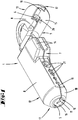
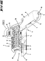
- the Figures 1 to 6 show a first side of an exemplary stripping tool 1 for removing an outer jacket 2 and / or a wire insulation 3 of an electrical single or multi-core cable 4.
- the stripping tool 1 has two hollow body partial areas 12, 13 forming a hollow body 9, which by an angle ⁇ (see Figure 2 ) are arranged to each other. The angle ⁇ is approximately 135 ° here.
- the two hollow body part regions 12, 13 have a common first hollow body part shell 7, on which two pivot axes 5, 6 are arranged.
- a first pivot axis 5 is assigned to the first hollow body portion 12, while a second pivot axis 6 is assigned to the second hollow body portion 13.
- a second hollow part shell 8 is arranged on the pivot axes 5, 6, which can be pivoted about the respective pivot axis 5, 6 relative to the first hollow part shell 7.
- the pivot axes 5, 6 are arranged on opposite shell edges 19 of the first hollow body shell 7.
- a cutting element 10 is located in the hollow body 9 both on the first hollow body part region 12 and on the second hollow body part region 13 (see Figure 4 ), in particular a pair of cutting elements, the cutting edge 11 of which runs perpendicular to the pivot axes 5, 6.
- This cutting element 10 is used in particular to remove an outer jacket 2 of a multi-core cable 4.
- the hollow body 9 has an opening 16 through which a cable 4 to be stripped can be guided.
- the end region 17 of the hollow body part region 12 that supports the opening 16 also has a cone 18 in its outer contour that widens in one direction away from the opening 16.
- the cone 18 points here an angle ⁇ of approximately 45 ° relative to the plane of the opening 16 (see Figure 2 ).
- first hollow body part region 12 and the second hollow body part region 13 of the stripping tool 1 form a pistol-like shape, so that a user of the stripping tool 1 uses a gripping surface 15 of the hollow body part regions 12, 13 as a handle part and the other hollow body part region 13, 12 as the actual tool for stripping a cable 4th
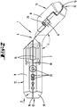
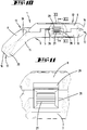
- the stripping tool 1 has a plurality of cutting elements 21, in particular cutting element pairs, here six cutting elements 21, on a shell edge 19. These are arranged in such a way that corresponding cutting elements 21 of a pair are arranged on the first hollow body shell 7 and the second hollow body shell 8.
- a guide link 22 is formed which has a plurality of webs 23 for guiding a cable 4 into the hollow body 9 (see Figures 5 and 6 ).
- the webs 23 are divided into two partial guide slots 24 of the guide slot 22, the partial guide slots 24 extending parallel to and on opposite sides of the shell edge 19 having the cutting elements 21.
- Figure 4 shows the stripping tool 1 in an open state, the two second hollow body shell parts 8 being pivoted about the pivot axes 5, 6.
- a marking 25 formed on the first hollow body partial shell 7 can be seen, which indicates a distance from a cutting element 21 to a line of the marking 25.
- a length to be stripped from a cable 4 can thereby be measured.
- the individual lines of the marking 25 are assigned millimeter specifications, here "8", "12", "16".
- attack flaps 14 are formed on the hollow body part shells 7, 8, which serve to compress the two hollow body part shells 7, 8 during the stripping process.
- the attack tabs 14 extend from the circumferential surface of the hollow body 9 in a direction which is arranged perpendicular to a plane spanned by the hollow body partial areas 12, 13.
- Figure 5 shows the stripping tool 1 with two cables 4 inserted into the hollow body 9.
- the cables 4 have different diameters from one another, the cable 4 inserted into the first hollow body part region 12 having a larger diameter than the cable 4 inserted into the second hollow body part region 13 during the stripping process, however, only one cable is located in either the first hollow body part region 12 or the second hollow body part region 13.
- the respective hollow body part region 12, 13 is optimized for specific diameters of a cable 4.
- the first hollow body part area 12 can be designed for round and damp room cables with a diameter of 8 mm to 13 mm
- the second hollow body part area 13 is optimized for data cables with a diameter of 4 mm to 8 mm.
- the cutting element 10, the opening 16 or the inner diameter of the hollow body partial areas 12, 13 can be formed.
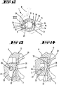
- the Figures 7 to 9 show a back of the (in the Figures 1 - 6 shown) stripping tool 1, which has an indentation 20 on the peripheral surface of the second hollow body partial region 13, which recesses a peripheral partial region.
- the indentation 20 cuts out approximately an angular partial region of 130 ° from the circumference of the hollow body partial region 13.
- a cable 4 to be inserted into the hollow body 9 can be introduced into this indentation 20 and pressed transversely against the shell edge 19, until the hollow body part shells 7, 8 pivot away from one another.
- the restoring force of a spring (not shown) is to be overcome, which is arranged on the pivot axis 6 and tries to close the hollow body 9.
- Figure 7 shows the state in which a cable 4 lies in the indentation 20 and presses against the hollow body shell parts 7, 8.
- the cable 4 is supported against the inclined flanks of the recess 20.
- the cable 4 is already guided between the two hollow body shell parts 7, 8. Due to its restoring force, the spring closes the hollow body 9 immediately after the open shell edge 19 has been overcome by the cable 4.
- Figure 9 finally shows a cross section through the second hollow body part region 13 in the region of the indentation 20.
- the indentation 20 with an opening angle ⁇ of approximately 130 ° can be seen here from the otherwise circular circumference of the hollow body part region 13.
- the invention now functions, for example, in such a way that a user selects a hollow body partial region 12, 13 of the stripping tool 1 for stripping an outer jacket 2 from a cable 4, which part corresponds best to the diameter of the cable 4. If, for example, a cable 4 with a diameter of, for example, 6 mm is concerned, the second hollow body part area 13 is particularly suitable here.
- the user therefore grips the stripping tool 1 on the first hollow body part area 12, which is connected to the second hollow body part area 13 in a manner similar to a pistol .
- the gripping surface 15 of the first hollow body part area 12 serves to rest the hand of the user, in particular the ball of the hand and the ring and middle finger.
- the user grips the cable 4 to be stripped and presses it inside the indentation 20 against the hollow body part shells 7, 8 of the second hollow body partial area 13 (see Figures 7 and 9 ). If the user expends a force that is greater than the restoring force of the spring, which is assigned to the pivot axis 6, the second hollow part shell 8 pivots so that the cable 4 can be inserted into the hollow body 9. If necessary, the user now guides the stripping tool 1 along the outer jacket 2 of the cable 4 until a desired length of the cable 4 intended for stripping is reached. If the stripping tool 1 is carried out in a box that is difficult to access or in a cramped electrical box, the stripping tool 1 can be brought as close as possible to the desired place of use due to the cone 18 of the end region 17.
- the user For stripping, the user then grips the second hollow body part region 13 with the thumb and the index finger and presses the hollow body part shells 7, 8 against one another. As a result, the cable 4 is pressed onto the cutting element 10, so that when the cutting element 10 rotates around the cable 4, a corresponding cut is made which allows the outer jacket 2 to be removed.
- the user performs the rotation of the stripping tool 1 around the cable 4 in a conventional manner by rotating the wrist.
- stripping of a cable 4 can also be carried out in the first hollow body part region 12, wherein the engagement tabs 14 can be used there for pressing the hollow body part shells 7, 8 against one another.
- the user can still use the stripping tool 1 to remove a wire insulation 3 from a single-core cable 4.
- the user opens the first hollow body partial area 12 of the stripping tool 1 manually by pivoting the second hollow body shell 8 of the first hollow body region 12 relative to the first hollow body shell 7.
- the user selects a corresponding cutting element 21, which the user recognizes particularly advantageously by orientation on the irregularly arranged webs 23 of the guide link 22.
- the user can remember the web 23 closest to the desired cutting element 21 and quickly insert the cable 4 into the stripping tool 1.
- the user advantageously supports the cable 4 on the adjacent web 23, as a result of which the cable 4 is essentially aligned relative to the cutting element 21.
- the user can measure a desired length of the cable 4 to be stripped using the marking 25. If, for example, a length of twelve millimeters of the cable 4 is to be stripped, the user inserts the cable 4 into the stripping tool 1 up to the graduation with the millimeter specification "12".
- FIGS 10 to 18 show a second embodiment of a stripping tool 1, which essentially on the in the Figures 1 to 9 illustrated embodiment is based.
- a second hollow body shell 8 can be locked on the first hollow body shell 7, in particular in the shell closed position.
- Such a lock is shown in connection with the hollow body part region 12.
- such a lock is additionally or alternatively possible in the hollow body part region 13.
- Each second hollow body part shell 8 can be pivoted about an axle body 26 which extends in the longitudinal direction of the respective hollow body part region 12 or 13.
- This axle body 26 is preferably held in each case forming the pivot axis 5 or 6 on the edge side of the first hollow body partial shell 7, preference being given to an arrangement of the axle bodies 26 or the pivot axes 5 and 6 that is overall opposite with respect to the longitudinal extent of the stripping tool 1.
- the edge regions of the first and second hollow body partial shells 7 and 8, which are to be pointed towards one another in the joint region, are alternately nested within one another across the longitudinal extent, viewed over the longitudinal extent.
- a locking part 27 which can be displaced by sliding. This is positioned approximately in the middle of the longitudinal extent of the hollow body portion 13 on the hinge side of the arrangement.
- the locking part 27 is initially in a wall-side recess 28 of the fixed hollow body shell 7. This depression 28 is open towards the parting plane between the first hollow part shell 7 and the pivotable second hollow part shell 8.
- a locking recess 29 is formed on the outside of the wall thereof, which is also open in the direction of the parting plane.
- the locking part 27 is in the region of an elongated hole-like recess oriented perpendicular to the extension of the geometric pivot axis 30 penetrated by the associated axle body 26. As a result, the locking part 27 is guided perpendicularly to the axis alignment with essentially approximately tangential displaceability relative to the pivot axis on the bottom surface of the depression 28 and, moreover, is held captively on the stripping tool 1.
- the actuation or displacement of the locking part 27 can, as is also preferred, take place with one hand, for example due to the application of the thumb.
- Both bar end positions can, as preferred and also shown, be locked. As shown, such a latching takes place between the locking part 27 and the first hollow part shell 7.
- the latter has the corresponding surface of the locking part 27 in the region of the recess 28 a locking projection 31 which can be run over and which, in the locking and unlocking position, has locking recesses spaced apart from one another in the direction of displacement 32 of the locking member 27 is immersed.
- the outward surface of the locking part 27 can be ergonomically shaped, for example by a shell-like configuration.
- the surface can be a Have profiling for cheap power transmission.
- the surface can also be made at least partially more secure, for example by soft plastic components introduced in the two-component injection molding process.
- Such a configuration of the surface that is favorable with regard to the transmission of force can also be provided in the region of one or both engagement tabs 14 (cf. for example Figure 15 ).
- attack tabs 14 as shown in the Figures 15 to 18 not only and only serve to load the assigned shells in the direction of the closed position, but can also have a cutting function.
- the attack tabs 14 are formed as functional tabs 33. Starting from the first hollow body shell 7 and the second hollow body shell 8, these also each project freely beyond the circumferential surface, away from the pivot axis.
- the functional tabs 33 are formed in the hollow body portion 12 in the exemplary embodiment shown.
- the functional tabs 33 are with closed hollow body part shells 7 and 8 (as in Figure 15 shown) in overlap with one another, a preferably round through-opening 34 being formed in this closed position.
- This through-opening 34 is preferably formed in half by a corresponding recess in the area of the surfaces of the functional tabs 33 to be facing one another.
- the throughput opening 34 When the shell position is closed, the throughput opening 34 preferably extends in parallel alignment with the geometric pivot axis of the assigned hollow body part region. Furthermore, the throughput opening 34 is positioned between the functional tabs 33 in such a way that with reference to a cross section transverse to the longitudinal extent of the hollow body part region 12 as shown in FIG Figure 12 the through opening 34 extends to the side of the shell wall.
- At least one functional tab 33 has a cutting element, preferably the functional tab 33 assigned to the pivotable second hollow body partial shell 8.
- the cutting edge 35 of the cutting element projects into the free cross-sectional area of the through-opening 34 and extends here essentially in an alignment according to the geometric pivot axis of the same hollow body part region.
- the throughput opening 34 with the cutting element having the cutting edge 35 is preferably used for cutting the sheathing of a cable along the longitudinal orientation, in order to facilitate the sheathing, in particular over longer cable lengths. In such a cutting process, the cable is pulled through the through opening 34.
- the cable can result in an axial extension of the throughput opening in the hollow body part region 13, in particular in a corresponding section of the hollow body part shell 8 in question.
- a guide 36 in the form of a system groove which can be accessed from the outside and proves to be formed on the hollow body part shell 8 of the hollow body part area 13, has proven particularly favorable.
- both the first hollow body portion 12 and the second hollow body portion 13 can carry cutting elements 21.
- the orientation of the pivot axis 5, 6 relative to the shell edges 19 is also variable.
- the stripping tool can carry both an indentation 20 and cutting elements 21 on the shell edge 19 of a hollow body partial region 12, 13.
- a conical end region 17 can of course also be combined.
- the stripping tool 1 can be designed as a right-handed or left-handed tool, with the pivot axes 5, 6 optionally being moved to an opposite shell edge 19 between the two hollow body shell parts 7, 8. Further combinations of features are conceivable.
- a stripping tool which is characterized in that the stripping tool 1 has at least two hollow body partial areas 12, 13 arranged at an angle ⁇ between approximately 90 ° and 170 °, in particular between 110 ° and 150 °, at least one first hollow body partial area 12, 13 has two hollow body partial shells 7, 8 which are pivotable relative to one another, of which at least one hollow body partial shell 7, 8 can be pivoted without displacement of a second hollow body partial region 13, 12.
- a stripping tool which is characterized in that the two hollow body sections 12, 13 form a pistol-like shape of the stripping tool 1.
- a stripping tool which is characterized in that two hollow body partial areas 12, 13 each have two pivotable hollow body partial shells 7, 8.
- a stripping tool which is characterized in that a first hollow body portion 12 is designed to receive a cable 4 with a first diameter, and a second hollow body portion 13 is designed to receive a cable 4 with a second diameter that differs from the first diameter .
- a stripping tool which is characterized by at least two pivot axes 5, 6, which are arranged on the one hand on a common first hollow part shell 7 and on the other hand on separate second hollow part shells 8.
- a stripping tool which is characterized in that a first and a second pivot axis 5, 6 of the second hollow body shell parts 8 are arranged opposite one another.
- a stripping tool which is characterized in that a hollow body shell 8 of a hollow body region 12, 13 can be locked in a closed position.
- a stripping tool which is characterized in that a hollow body shell 8 is pivotable by means of an axis body 26 extending in the longitudinal direction of the hollow body shell 8.
- a stripping tool which is characterized in that the axle body 26 passes through a locking part 27.
- a stripping tool which is characterized in that the locking part 27 is movable transversely to the longitudinal direction of the axle body 26 in a locking and unlocking position.
- a stripping tool which is characterized in that the locking part 27 is locked both in the locking and unlocking position on the same hollow body part shell 7.
- a stripping tool which is characterized in that a first hollow body partial area 12 has gripping tabs 14 projecting beyond a peripheral surface for pressing together the hollow body partial shells 7, 8 forming the hollow body 9 by means of a thumb and an index finger of a hand, and wherein a second hollow body partial area 13 has a gripping surface 15 simultaneous application of a ball of the hand.
- a stripping tool which is characterized in that the hollow body 9 formed by the two hollow body partial shells 7, 8 has, at least with respect to an end region 17 in its outer contour, a cone 18 which widens in the direction of a gripping surface 15 of the stripping tool 1.
- a stripping tool which is characterized in that a circumferential surface of the cone 18 has an angle ⁇ of approximately 30 ° to 60 ° to an end surface of the end region 17.
- a stripping tool which is characterized in that the cone 18 is formed starting from an end face of the end region 17 over a length of 5 mm to 20 mm.
- a stripping tool which is characterized in that the hollow body 9 has an indentation 20 for pressing a cable 4 into the hollow body 9 on a shell edge 19, on which the hollow body partial shells 7, 8 can be pivoted toward one another, which indentation 20 in particular has an opening angle ⁇ has less than 180 °.
- a stripping tool which is characterized in that the opening angle ⁇ of the indentation 20 corresponds to an opening width of 1 mm to 20 mm, in particular corresponds to a diameter of a cable 4 to be accommodated in the hollow body 9.
- a stripping tool which is characterized in that the pivot axis 5, 6 is assigned a spring, by means of the restoring force of which the hollow body partial shells 7, 8 can be pivoted towards one another to form a hollow body 9 or can be pivoted away from one another to open the hollow body 9.
- a stripping tool which is characterized in that the cutting elements 21 are assigned a guide link 22, which has at least one web 23 formed laterally to a cutting element 21 for aligning a cable 4 on a cutting element 21, in which case of a plurality of webs 23 which are formed in the direction of the shell edge 19 on opposite sides of two cutting elements 21, in particular two cutting elements 21 lying next to one another.
- a stripping tool which is characterized in that the guide link 22 has two partial guide links 24 arranged on sides of the cutting elements 21 opposite in a direction perpendicular to the shell edge 19.
- a stripping tool which is characterized in that at least one hollow body partial shell 7, 8 has a marking 25 formed in the insertion direction of a cable 4 behind a cutting element 21, which enables a user to measure an insertion length to be stripped analogously.
- a stripping tool which is characterized in that the marking 25 is three-dimensionally physically shaped.
- a stripping tool which is characterized in that a first hollow body partial region 12, 13 has functional tabs 33 projecting beyond a circumferential surface, at least one functional tab 33 having a cutting element with a cutting edge 35 extending in the direction of the pivot axis 5, 6.
- a stripping tool which is characterized in that the functional tabs 33 are at least in overlap with one another at least in the area of the cutting edge 35 when the hollow body partial shells 7, 8 are closed.
- both the first hollow body portion 12 and the second hollow body portion 13 can carry cutting elements 21.
- the orientation of the pivot axis 5, 6 relative to the shell edges 19 is also variable.
- the stripping tool can carry both an indentation 20 and cutting elements 21 on the shell edge 19 of a hollow body partial region 12, 13.
- a conical end region 17 can of course also be combined.
- the stripping tool 1 can be designed as a right-handed or left-handed tool, with the pivot axes 5, 6 optionally being moved to an opposite shell edge 19 between the two hollow body shell parts 7, 8. Further combinations of features are conceivable.
Landscapes
- Knives (AREA)
- Removal Of Insulation Or Armoring From Wires Or Cables (AREA)
Claims (15)
- Outil de dénudage (1) pour enlever une gaine extérieure (2) et/ou une isolation de conducteur (3) d'un câble électrique (4) à un ou plusieurs conducteurs, dans lequel l'outil de dénudage (1) présente des coques partielles de corps creux (7, 8) qui sont reliées entre elles par un axe de pivotement commun (5, 6) et qui peuvent pivoter l'une/les unes vers l'autre/les autres pour former un corps creux (9) de réception au moins partielle d'un câble (4), dans lequel les coques partielles de corps creux (7, 8) présentent au moins un élément de coupe (10, 21), caractérisé en ce que l'outil de dénudage (1) présente au moins deux régions partielles de corps creux (12, 13) agencées l'une par rapport à l'autre avec un angle (α) compris entre environ 90° et 170°, en particulier entre 110° et 150°, dans lequel au moins une première région partielle de corps creux (12, 13) présente deux coques partielles de corps creux (7, 8) pouvant pivoter l'une par rapport à l'autre dont au moins une coque partielle de corps creux (7, 8) peut pivoter sans déplacement d'une deuxième région partielle de corps creux (13, 12).
- Outil de dénudage (1) selon la revendication 1, caractérisé en ce que les deux régions partielles du corps creux (12, 13) forment une forme de pistolet de l'outil de dénudage (1).
- Outil de dénudage selon l'une des revendications précédentes, caractérisé en ce que deux régions partielles de corps creux (12, 13) présentent chacune deux coques partielles de corps creux (7, 8) mobiles de manière pivotante.
- Outil de dénudage (1) selon l'une des revendications précédentes, caractérisé en ce que la première région partielle de corps creux (12) est formée pour recevoir un câble (4) ayant un premier diamètre et que la deuxième région partielle de corps creux (13) est formée pour recevoir un câble (4) ayant un deuxième diamètre.
- Outil de dénudage (1) selon l'une des revendications précédentes, caractérisé par au moins deux axes de pivotement (5, 6) qui sont associés, d'une part, à une première coque partielle de corps creux (7) commune et, d'autre part, à des deuxièmes coques partielles de corps creux (8) mutuellement séparées.
- Outil de dénudage (1) selon la revendication 5, caractérisé en ce qu'un premier et un deuxième axe de pivotement (5, 6) des deuxièmes coquilles partielles de corps creux (8) sont agencés en face l'un de l'autre.
- Outil de dénudage (1) selon l'une des revendications précédentes, caractérisé en ce qu'une coque partielle de corps creux (8) d'une région partielle de corps creux (12, 13) est verrouillable en position fermée.
- Outil de dénudage (1) selon l'une des revendications précédentes, caractérisé en ce qu'une coque partielle de corps creux (8) peut pivoter au moyen d'un élément formant axe (26) s'étendant dans la direction longitudinale des coques partielles de corps creux (8).
- Outil de dénudage (1) selon la revendication 8, caractérisé en ce que l'élément formant axe (26) passe à travers une pièce de verrouillage (27).
- Outil de dénudage (1) selon la revendication 9, caractérisé en ce que la pièce de verrouillage (27) est mobile dans une position de verrouillage et de déverrouillage transversalement à la direction longitudinale de l'élément formant axe (26).
- Outil de dénudage (1) selon l'une des revendications 9 ou 10, caractérisé en ce que la pièce de verrouillage (27) est jointe par encliquetage/interverrouillage à la même coque partielle de corps creux (7) à la fois en position verrouillée et déverrouillée.
- Outil de dénudage (1) selon l'une des revendications précédentes, caractérisé en ce que la première région partielle de corps creux (12) présente des languettes d'actionnement (14) faisant saillie sur une surface périphérique pour presser ensemble les coques partielles de corps creux (7, 8) formant le corps creux (9) au moyen du pouce et de l'index d'une main, et la deuxième région partielle de corps creux (13) présente une surface de préhension (15) pour l'application simultané d'une paume de la main.
- Outil de dénudage (1) selon l'une des revendications précédentes, caractérisé en ce que le corps creux (9) formé par les deux coques partielles de corps creux (7, 8) présente dans son contour extérieur, au moins par rapport à une zone d'extrémité (17), un cône (18) qui s'élargit en direction d'une surface de préhension (15) de l'outil de dénudage (1).
- Outil de dénudage (1) selon la revendication 13, caractérisé en ce qu'une surface périphérique du cône (18) présente un angle (β) d'environ 30° à 60° par rapport à une face frontale de la zone d'extrémité (17).
- Outil de dénudage selon l'une des revendications 13 ou 14, caractérisé en ce que le cône (18) est formé à partir d'une face frontale de la zone d'extrémité (17) sur une longueur de 5 mm à 20 mm.
Priority Applications (3)
| Application Number | Priority Date | Filing Date | Title |
|---|---|---|---|
| EP20160300.8A EP3680999B1 (fr) | 2015-07-17 | 2016-07-05 | Outil de dénudage |
| PL20160300T PL3680999T3 (pl) | 2015-07-17 | 2016-07-05 | Przyrząd do usuwania izolacji |
| PL16738708T PL3326251T3 (pl) | 2015-07-17 | 2016-07-05 | Przyrząd do usuwania izolacji |
Applications Claiming Priority (3)
| Application Number | Priority Date | Filing Date | Title |
|---|---|---|---|
| DE102015111693 | 2015-07-17 | ||
| DE102016101940.2A DE102016101940B4 (de) | 2015-07-17 | 2016-02-04 | Abisolierwerkzeug |
| PCT/EP2016/065830 WO2017012858A2 (fr) | 2015-07-17 | 2016-07-05 | Outil de dénudage |
Related Child Applications (2)
| Application Number | Title | Priority Date | Filing Date |
|---|---|---|---|
| EP20160300.8A Division EP3680999B1 (fr) | 2015-07-17 | 2016-07-05 | Outil de dénudage |
| EP20160300.8A Division-Into EP3680999B1 (fr) | 2015-07-17 | 2016-07-05 | Outil de dénudage |
Publications (2)
| Publication Number | Publication Date |
|---|---|
| EP3326251A2 EP3326251A2 (fr) | 2018-05-30 |
| EP3326251B1 true EP3326251B1 (fr) | 2020-04-15 |
Family
ID=57630380
Family Applications (2)
| Application Number | Title | Priority Date | Filing Date |
|---|---|---|---|
| EP16738708.3A Active EP3326251B1 (fr) | 2015-07-17 | 2016-07-05 | Outil de dénudage |
| EP20160300.8A Active EP3680999B1 (fr) | 2015-07-17 | 2016-07-05 | Outil de dénudage |
Family Applications After (1)
| Application Number | Title | Priority Date | Filing Date |
|---|---|---|---|
| EP20160300.8A Active EP3680999B1 (fr) | 2015-07-17 | 2016-07-05 | Outil de dénudage |
Country Status (7)
| Country | Link |
|---|---|
| EP (2) | EP3326251B1 (fr) |
| CN (1) | CN107851979B (fr) |
| DE (3) | DE102016101940B4 (fr) |
| ES (1) | ES2797807T3 (fr) |
| PL (2) | PL3680999T3 (fr) |
| TW (1) | TWI710188B (fr) |
| WO (1) | WO2017012858A2 (fr) |
Families Citing this family (7)
| Publication number | Priority date | Publication date | Assignee | Title |
|---|---|---|---|---|
| DE202017107094U1 (de) * | 2017-11-23 | 2018-01-02 | Weicon Gmbh & Co Kg | Coaxialkabel-Abisolierwerkzeug |
| DE112020002278A5 (de) * | 2019-05-06 | 2022-01-20 | Rennsteig Werkzeuge Gmbh | Zangenartiges Werkzeug |
| DE112020002275A5 (de) * | 2019-05-06 | 2022-04-07 | Rennsteig Werkzeuge Gmbh | Als Handwerkzeug ausgebildetes Abisolierwerkzeug, Schneidenteil für ein Abisolierwerkzeug sowie Verfahren zum Abisolieren eines Kabels |
| JP7088887B2 (ja) | 2019-08-29 | 2022-06-21 | 矢崎総業株式会社 | ケーブルの被覆除去方法およびケーブルの被覆除去装置 |
| MX2023011396A (es) * | 2021-03-31 | 2023-11-28 | Ppc Broadband Fiber Ltd | Herramienta de corte de ventana en cable multifibra. |
| CN113328323B (zh) * | 2021-07-06 | 2024-09-17 | 昆山频谱电子科技有限公司 | 一种便携式柔性电缆剥线装置 |
| DE102023210532A1 (de) | 2023-10-25 | 2025-04-30 | Robert Bosch Gesellschaft mit beschränkter Haftung | Werkzeug, Werkzeugmaschinensystem und Verfahren zu einem Betrieb des Werkzeugs |
Family Cites Families (12)
| Publication number | Priority date | Publication date | Assignee | Title |
|---|---|---|---|---|
| CH496343A (de) * | 1967-03-15 | 1970-09-15 | Standard Telephon & Radio Ag | Abisoliervorrichtung |
| DE3844278A1 (de) | 1988-03-17 | 1990-07-05 | Josef Krampe | Abmantelungswerkzeug zur entfernung der isolierung ein- oder mehradriger kabel |
| DE3904323A1 (de) * | 1989-02-14 | 1990-08-16 | P W Weidling & Sohn Gmbh & Co | Geraet zur entfernung der aeusseren isolierung von mehradrigen kabeln |
| DE29814771U1 (de) * | 1998-08-18 | 1998-11-19 | Krampe, Josef, 59387 Ascheberg | Abmantelungswerkzeug |
| CN2506398Y (zh) * | 2001-09-26 | 2002-08-21 | 陈纯琼 | 组合式套筒棘轮扳手 |
| DE50303961D1 (de) | 2003-08-14 | 2006-08-03 | Krampe Kg | Abisolierwerkzeug Uniplus |
| US7171712B2 (en) * | 2004-07-07 | 2007-02-06 | Ideal Industries, Inc. | Wire stripper with strip length scale |
| US8151670B2 (en) * | 2008-08-01 | 2012-04-10 | Nelson James M | Sheath and conductor strippers |
| DE202009000142U1 (de) | 2009-01-05 | 2009-04-09 | KAUW YEHI INDUSTRIAL CO., LTD., Tucheng City | Handwerkzeug |
| CN202142814U (zh) * | 2011-06-30 | 2012-02-08 | 山东省电力学校 | 电工导线去皮工具 |
| CN203826859U (zh) * | 2014-04-30 | 2014-09-10 | 国家电网公司 | 绝缘导线专用剥线器 |
| DE202014106142U1 (de) | 2014-12-18 | 2015-01-15 | Krampe Immobilien Gmbh & Co. Kg | Abmantelungswerkzeug für Rundkabel mit dünner Isolierung |
-
2016
- 2016-02-04 DE DE102016101940.2A patent/DE102016101940B4/de active Active
- 2016-07-05 WO PCT/EP2016/065830 patent/WO2017012858A2/fr not_active Ceased
- 2016-07-05 EP EP16738708.3A patent/EP3326251B1/fr active Active
- 2016-07-05 DE DE202016008391.1U patent/DE202016008391U1/de not_active Expired - Lifetime
- 2016-07-05 DE DE202016008354.7U patent/DE202016008354U1/de not_active Withdrawn - After Issue
- 2016-07-05 ES ES16738708T patent/ES2797807T3/es active Active
- 2016-07-05 PL PL20160300T patent/PL3680999T3/pl unknown
- 2016-07-05 CN CN201680041891.2A patent/CN107851979B/zh active Active
- 2016-07-05 EP EP20160300.8A patent/EP3680999B1/fr active Active
- 2016-07-05 PL PL16738708T patent/PL3326251T3/pl unknown
- 2016-07-15 TW TW105122386A patent/TWI710188B/zh active
Non-Patent Citations (1)
| Title |
|---|
| None * |
Also Published As
| Publication number | Publication date |
|---|---|
| PL3326251T3 (pl) | 2020-09-21 |
| EP3326251A2 (fr) | 2018-05-30 |
| TWI710188B (zh) | 2020-11-11 |
| HK1255031A1 (zh) | 2019-08-02 |
| DE102016101940B4 (de) | 2026-03-19 |
| WO2017012858A3 (fr) | 2017-03-16 |
| EP3680999A1 (fr) | 2020-07-15 |
| WO2017012858A2 (fr) | 2017-01-26 |
| TW201712983A (zh) | 2017-04-01 |
| CN107851979B (zh) | 2020-02-14 |
| EP3680999B1 (fr) | 2022-01-12 |
| DE202016008354U1 (de) | 2017-08-21 |
| ES2797807T3 (es) | 2020-12-03 |
| PL3680999T3 (pl) | 2022-05-02 |
| DE202016008391U1 (de) | 2017-10-10 |
| CN107851979A (zh) | 2018-03-27 |
| DE102016101940A1 (de) | 2017-01-19 |
Similar Documents
| Publication | Publication Date | Title |
|---|---|---|
| EP3326251B1 (fr) | Outil de dénudage | |
| EP4311627B1 (fr) | Mâchoires de pressage ainsi que pince de pressage avec deux mâchoires de serrage | |
| DE69831996T2 (de) | Handwerkzeug | |
| DE2162818B2 (de) | Mehrzweckzange fuer elektriker | |
| EP3718184B1 (fr) | Mâchoires de serrage pour une pince à dénuder et pince à dénuder | |
| EP3784438A1 (fr) | Pince | |
| CH678906A5 (fr) | ||
| EP3302886B1 (fr) | Outil de sertissage, de pressage ou de façonnage d'une pièce | |
| EP3723928B1 (fr) | Dispositif de coupe pour couper des tubes ondulés à longueur et guidage des saillies dans un tel dispositif de coupe | |
| DE69801155T2 (de) | Werkzeug und verfahren zum umhüllen von kabeln | |
| DE19607949C1 (de) | Abisoliervorrichtung | |
| EP4052871B1 (fr) | Appareil de coupe permettant de découper des tubes ou des manchons | |
| EP0802590A2 (fr) | Outil de connexion | |
| WO2022135917A1 (fr) | Bouchon destiné à être fixé sur des conduites et d'autres éléments allongés | |
| EP1816716A2 (fr) | Outil à dénuder | |
| WO2021043807A1 (fr) | Insert de sertissage et pince de sertissage | |
| EP1507324B1 (fr) | Dispositif de dénudage Uniplus | |
| DE3512065C1 (de) | Vorrichtung zum Entfernen eines Abschnittes einer Ummantelung von im wesentlichen stangenförmigen Gegenständen, insbesondere elektrischen Kabeln | |
| DE102016103972A1 (de) | Kabelmesser | |
| DE10110869C2 (de) | Abisolierzange | |
| DE202024101563U1 (de) | Zange | |
| DE2911374C2 (de) | Spannvorrichtung | |
| WO2024188853A1 (fr) | Appareil tenu à la main muni d'une lame | |
| EP4229721A1 (fr) | Capuchon protecteur |
Legal Events
| Date | Code | Title | Description |
|---|---|---|---|
| STAA | Information on the status of an ep patent application or granted ep patent |
Free format text: STATUS: THE INTERNATIONAL PUBLICATION HAS BEEN MADE |
|
| PUAI | Public reference made under article 153(3) epc to a published international application that has entered the european phase |
Free format text: ORIGINAL CODE: 0009012 |
|
| STAA | Information on the status of an ep patent application or granted ep patent |
Free format text: STATUS: REQUEST FOR EXAMINATION WAS MADE |
|
| 17P | Request for examination filed |
Effective date: 20180201 |
|
| AK | Designated contracting states |
Kind code of ref document: A2 Designated state(s): AL AT BE BG CH CY CZ DE DK EE ES FI FR GB GR HR HU IE IS IT LI LT LU LV MC MK MT NL NO PL PT RO RS SE SI SK SM TR |
|
| AX | Request for extension of the european patent |
Extension state: BA ME |
|
| RIN1 | Information on inventor provided before grant (corrected) |
Inventor name: RIEPE, BERND Inventor name: PECH, MARTIN Inventor name: MAROVIC, FILIP Inventor name: SCHLEIMINGER, JAN |
|
| DAV | Request for validation of the european patent (deleted) | ||
| DAX | Request for extension of the european patent (deleted) | ||
| REG | Reference to a national code |
Ref country code: HK Ref legal event code: DE Ref document number: 1255031 Country of ref document: HK |
|
| GRAP | Despatch of communication of intention to grant a patent |
Free format text: ORIGINAL CODE: EPIDOSNIGR1 |
|
| STAA | Information on the status of an ep patent application or granted ep patent |
Free format text: STATUS: GRANT OF PATENT IS INTENDED |
|
| INTG | Intention to grant announced |
Effective date: 20191104 |
|
| GRAS | Grant fee paid |
Free format text: ORIGINAL CODE: EPIDOSNIGR3 |
|
| GRAA | (expected) grant |
Free format text: ORIGINAL CODE: 0009210 |
|
| STAA | Information on the status of an ep patent application or granted ep patent |
Free format text: STATUS: THE PATENT HAS BEEN GRANTED |
|
| AK | Designated contracting states |
Kind code of ref document: B1 Designated state(s): AL AT BE BG CH CY CZ DE DK EE ES FI FR GB GR HR HU IE IS IT LI LT LU LV MC MK MT NL NO PL PT RO RS SE SI SK SM TR |
|
| REG | Reference to a national code |
Ref country code: CH Ref legal event code: EP |
|
| REG | Reference to a national code |
Ref country code: DE Ref legal event code: R096 Ref document number: 502016009559 Country of ref document: DE |
|
| REG | Reference to a national code |
Ref country code: IE Ref legal event code: FG4D Free format text: LANGUAGE OF EP DOCUMENT: GERMAN |
|
| REG | Reference to a national code |
Ref country code: AT Ref legal event code: REF Ref document number: 1258404 Country of ref document: AT Kind code of ref document: T Effective date: 20200515 |
|
| REG | Reference to a national code |
Ref country code: NL Ref legal event code: MP Effective date: 20200415 |
|
| REG | Reference to a national code |
Ref country code: LT Ref legal event code: MG4D |
|
| PG25 | Lapsed in a contracting state [announced via postgrant information from national office to epo] |
Ref country code: NL Free format text: LAPSE BECAUSE OF FAILURE TO SUBMIT A TRANSLATION OF THE DESCRIPTION OR TO PAY THE FEE WITHIN THE PRESCRIBED TIME-LIMIT Effective date: 20200415 Ref country code: SE Free format text: LAPSE BECAUSE OF FAILURE TO SUBMIT A TRANSLATION OF THE DESCRIPTION OR TO PAY THE FEE WITHIN THE PRESCRIBED TIME-LIMIT Effective date: 20200415 Ref country code: LT Free format text: LAPSE BECAUSE OF FAILURE TO SUBMIT A TRANSLATION OF THE DESCRIPTION OR TO PAY THE FEE WITHIN THE PRESCRIBED TIME-LIMIT Effective date: 20200415 Ref country code: PT Free format text: LAPSE BECAUSE OF FAILURE TO SUBMIT A TRANSLATION OF THE DESCRIPTION OR TO PAY THE FEE WITHIN THE PRESCRIBED TIME-LIMIT Effective date: 20200817 Ref country code: IS Free format text: LAPSE BECAUSE OF FAILURE TO SUBMIT A TRANSLATION OF THE DESCRIPTION OR TO PAY THE FEE WITHIN THE PRESCRIBED TIME-LIMIT Effective date: 20200815 Ref country code: FI Free format text: LAPSE BECAUSE OF FAILURE TO SUBMIT A TRANSLATION OF THE DESCRIPTION OR TO PAY THE FEE WITHIN THE PRESCRIBED TIME-LIMIT Effective date: 20200415 Ref country code: GR Free format text: LAPSE BECAUSE OF FAILURE TO SUBMIT A TRANSLATION OF THE DESCRIPTION OR TO PAY THE FEE WITHIN THE PRESCRIBED TIME-LIMIT Effective date: 20200716 Ref country code: NO Free format text: LAPSE BECAUSE OF FAILURE TO SUBMIT A TRANSLATION OF THE DESCRIPTION OR TO PAY THE FEE WITHIN THE PRESCRIBED TIME-LIMIT Effective date: 20200715 |
|
| PG25 | Lapsed in a contracting state [announced via postgrant information from national office to epo] |
Ref country code: RS Free format text: LAPSE BECAUSE OF FAILURE TO SUBMIT A TRANSLATION OF THE DESCRIPTION OR TO PAY THE FEE WITHIN THE PRESCRIBED TIME-LIMIT Effective date: 20200415 Ref country code: BG Free format text: LAPSE BECAUSE OF FAILURE TO SUBMIT A TRANSLATION OF THE DESCRIPTION OR TO PAY THE FEE WITHIN THE PRESCRIBED TIME-LIMIT Effective date: 20200715 Ref country code: HR Free format text: LAPSE BECAUSE OF FAILURE TO SUBMIT A TRANSLATION OF THE DESCRIPTION OR TO PAY THE FEE WITHIN THE PRESCRIBED TIME-LIMIT Effective date: 20200415 Ref country code: LV Free format text: LAPSE BECAUSE OF FAILURE TO SUBMIT A TRANSLATION OF THE DESCRIPTION OR TO PAY THE FEE WITHIN THE PRESCRIBED TIME-LIMIT Effective date: 20200415 |
|
| REG | Reference to a national code |
Ref country code: ES Ref legal event code: FG2A Ref document number: 2797807 Country of ref document: ES Kind code of ref document: T3 Effective date: 20201203 |
|
| PG25 | Lapsed in a contracting state [announced via postgrant information from national office to epo] |
Ref country code: AL Free format text: LAPSE BECAUSE OF FAILURE TO SUBMIT A TRANSLATION OF THE DESCRIPTION OR TO PAY THE FEE WITHIN THE PRESCRIBED TIME-LIMIT Effective date: 20200415 |
|
| REG | Reference to a national code |
Ref country code: DE Ref legal event code: R097 Ref document number: 502016009559 Country of ref document: DE |
|
| PG25 | Lapsed in a contracting state [announced via postgrant information from national office to epo] |
Ref country code: CZ Free format text: LAPSE BECAUSE OF FAILURE TO SUBMIT A TRANSLATION OF THE DESCRIPTION OR TO PAY THE FEE WITHIN THE PRESCRIBED TIME-LIMIT Effective date: 20200415 Ref country code: RO Free format text: LAPSE BECAUSE OF FAILURE TO SUBMIT A TRANSLATION OF THE DESCRIPTION OR TO PAY THE FEE WITHIN THE PRESCRIBED TIME-LIMIT Effective date: 20200415 Ref country code: DK Free format text: LAPSE BECAUSE OF FAILURE TO SUBMIT A TRANSLATION OF THE DESCRIPTION OR TO PAY THE FEE WITHIN THE PRESCRIBED TIME-LIMIT Effective date: 20200415 Ref country code: EE Free format text: LAPSE BECAUSE OF FAILURE TO SUBMIT A TRANSLATION OF THE DESCRIPTION OR TO PAY THE FEE WITHIN THE PRESCRIBED TIME-LIMIT Effective date: 20200415 Ref country code: SM Free format text: LAPSE BECAUSE OF FAILURE TO SUBMIT A TRANSLATION OF THE DESCRIPTION OR TO PAY THE FEE WITHIN THE PRESCRIBED TIME-LIMIT Effective date: 20200415 |
|
| PLBE | No opposition filed within time limit |
Free format text: ORIGINAL CODE: 0009261 |
|
| STAA | Information on the status of an ep patent application or granted ep patent |
Free format text: STATUS: NO OPPOSITION FILED WITHIN TIME LIMIT |
|
| PG25 | Lapsed in a contracting state [announced via postgrant information from national office to epo] |
Ref country code: SK Free format text: LAPSE BECAUSE OF FAILURE TO SUBMIT A TRANSLATION OF THE DESCRIPTION OR TO PAY THE FEE WITHIN THE PRESCRIBED TIME-LIMIT Effective date: 20200415 Ref country code: MC Free format text: LAPSE BECAUSE OF FAILURE TO SUBMIT A TRANSLATION OF THE DESCRIPTION OR TO PAY THE FEE WITHIN THE PRESCRIBED TIME-LIMIT Effective date: 20200415 |
|
| REG | Reference to a national code |
Ref country code: CH Ref legal event code: PL |
|
| 26N | No opposition filed |
Effective date: 20210118 |
|
| REG | Reference to a national code |
Ref country code: BE Ref legal event code: MM Effective date: 20200731 |
|
| PG25 | Lapsed in a contracting state [announced via postgrant information from national office to epo] |
Ref country code: IE Free format text: LAPSE BECAUSE OF NON-PAYMENT OF DUE FEES Effective date: 20200705 Ref country code: LI Free format text: LAPSE BECAUSE OF NON-PAYMENT OF DUE FEES Effective date: 20200731 Ref country code: LU Free format text: LAPSE BECAUSE OF NON-PAYMENT OF DUE FEES Effective date: 20200705 Ref country code: CH Free format text: LAPSE BECAUSE OF NON-PAYMENT OF DUE FEES Effective date: 20200731 |
|
| PG25 | Lapsed in a contracting state [announced via postgrant information from national office to epo] |
Ref country code: BE Free format text: LAPSE BECAUSE OF NON-PAYMENT OF DUE FEES Effective date: 20200731 Ref country code: SI Free format text: LAPSE BECAUSE OF FAILURE TO SUBMIT A TRANSLATION OF THE DESCRIPTION OR TO PAY THE FEE WITHIN THE PRESCRIBED TIME-LIMIT Effective date: 20200415 |
|
| PG25 | Lapsed in a contracting state [announced via postgrant information from national office to epo] |
Ref country code: MT Free format text: LAPSE BECAUSE OF FAILURE TO SUBMIT A TRANSLATION OF THE DESCRIPTION OR TO PAY THE FEE WITHIN THE PRESCRIBED TIME-LIMIT Effective date: 20200415 Ref country code: CY Free format text: LAPSE BECAUSE OF FAILURE TO SUBMIT A TRANSLATION OF THE DESCRIPTION OR TO PAY THE FEE WITHIN THE PRESCRIBED TIME-LIMIT Effective date: 20200415 |
|
| PG25 | Lapsed in a contracting state [announced via postgrant information from national office to epo] |
Ref country code: MK Free format text: LAPSE BECAUSE OF FAILURE TO SUBMIT A TRANSLATION OF THE DESCRIPTION OR TO PAY THE FEE WITHIN THE PRESCRIBED TIME-LIMIT Effective date: 20200415 |
|
| REG | Reference to a national code |
Ref country code: AT Ref legal event code: MM01 Ref document number: 1258404 Country of ref document: AT Kind code of ref document: T Effective date: 20210705 |
|
| PG25 | Lapsed in a contracting state [announced via postgrant information from national office to epo] |
Ref country code: AT Free format text: LAPSE BECAUSE OF NON-PAYMENT OF DUE FEES Effective date: 20210705 |
|
| P01 | Opt-out of the competence of the unified patent court (upc) registered |
Effective date: 20230528 |
|
| PGFP | Annual fee paid to national office [announced via postgrant information from national office to epo] |
Ref country code: PL Payment date: 20250618 Year of fee payment: 10 |
|
| PGFP | Annual fee paid to national office [announced via postgrant information from national office to epo] |
Ref country code: TR Payment date: 20250619 Year of fee payment: 10 |
|
| PGFP | Annual fee paid to national office [announced via postgrant information from national office to epo] |
Ref country code: ES Payment date: 20250820 Year of fee payment: 10 |
|
| PGFP | Annual fee paid to national office [announced via postgrant information from national office to epo] |
Ref country code: DE Payment date: 20250704 Year of fee payment: 10 |
|
| PGFP | Annual fee paid to national office [announced via postgrant information from national office to epo] |
Ref country code: IT Payment date: 20250718 Year of fee payment: 10 |
|
| PGFP | Annual fee paid to national office [announced via postgrant information from national office to epo] |
Ref country code: GB Payment date: 20250703 Year of fee payment: 10 |
|
| PGFP | Annual fee paid to national office [announced via postgrant information from national office to epo] |
Ref country code: FR Payment date: 20250703 Year of fee payment: 10 |