EP4052959B1 - Unité de réglage de la longueur du siège, agencement de siège et véhicule automobile - Google Patents
Unité de réglage de la longueur du siège, agencement de siège et véhicule automobile Download PDFInfo
- Publication number
- EP4052959B1 EP4052959B1 EP21160795.7A EP21160795A EP4052959B1 EP 4052959 B1 EP4052959 B1 EP 4052959B1 EP 21160795 A EP21160795 A EP 21160795A EP 4052959 B1 EP4052959 B1 EP 4052959B1
- Authority
- EP
- European Patent Office
- Prior art keywords
- accordance
- adjustment unit
- shaft
- seat
- longitudinal adjustment
- Prior art date
- Legal status (The legal status is an assumption and is not a legal conclusion. Google has not performed a legal analysis and makes no representation as to the accuracy of the status listed.)
- Active
Links
Images

Classifications
-
- B—PERFORMING OPERATIONS; TRANSPORTING
- B60—VEHICLES IN GENERAL
- B60N—SEATS SPECIALLY ADAPTED FOR VEHICLES; VEHICLE PASSENGER ACCOMMODATION NOT OTHERWISE PROVIDED FOR
- B60N2/00—Seats specially adapted for vehicles; Arrangement or mounting of seats in vehicles
- B60N2/02—Seats specially adapted for vehicles; Arrangement or mounting of seats in vehicles the seat or part thereof being movable, e.g. adjustable
- B60N2/04—Seats specially adapted for vehicles; Arrangement or mounting of seats in vehicles the seat or part thereof being movable, e.g. adjustable the whole seat being movable
- B60N2/06—Seats specially adapted for vehicles; Arrangement or mounting of seats in vehicles the seat or part thereof being movable, e.g. adjustable the whole seat being movable slidable
- B60N2/07—Slide construction
- B60N2/0735—Position and orientation of the slide as a whole
-
- B—PERFORMING OPERATIONS; TRANSPORTING
- B60—VEHICLES IN GENERAL
- B60N—SEATS SPECIALLY ADAPTED FOR VEHICLES; VEHICLE PASSENGER ACCOMMODATION NOT OTHERWISE PROVIDED FOR
- B60N2/00—Seats specially adapted for vehicles; Arrangement or mounting of seats in vehicles
- B60N2/02—Seats specially adapted for vehicles; Arrangement or mounting of seats in vehicles the seat or part thereof being movable, e.g. adjustable
- B60N2/04—Seats specially adapted for vehicles; Arrangement or mounting of seats in vehicles the seat or part thereof being movable, e.g. adjustable the whole seat being movable
- B60N2/06—Seats specially adapted for vehicles; Arrangement or mounting of seats in vehicles the seat or part thereof being movable, e.g. adjustable the whole seat being movable slidable
- B60N2/067—Seats specially adapted for vehicles; Arrangement or mounting of seats in vehicles the seat or part thereof being movable, e.g. adjustable the whole seat being movable slidable by linear actuators, e.g. linear screw mechanisms
-
- B—PERFORMING OPERATIONS; TRANSPORTING
- B60—VEHICLES IN GENERAL
- B60N—SEATS SPECIALLY ADAPTED FOR VEHICLES; VEHICLE PASSENGER ACCOMMODATION NOT OTHERWISE PROVIDED FOR
- B60N2/00—Seats specially adapted for vehicles; Arrangement or mounting of seats in vehicles
- B60N2/02—Seats specially adapted for vehicles; Arrangement or mounting of seats in vehicles the seat or part thereof being movable, e.g. adjustable
- B60N2/0224—Non-manual adjustments, e.g. with electrical operation
- B60N2/02246—Electric motors therefor
-
- B—PERFORMING OPERATIONS; TRANSPORTING
- B60—VEHICLES IN GENERAL
- B60N—SEATS SPECIALLY ADAPTED FOR VEHICLES; VEHICLE PASSENGER ACCOMMODATION NOT OTHERWISE PROVIDED FOR
- B60N2/00—Seats specially adapted for vehicles; Arrangement or mounting of seats in vehicles
- B60N2/02—Seats specially adapted for vehicles; Arrangement or mounting of seats in vehicles the seat or part thereof being movable, e.g. adjustable
- B60N2/0224—Non-manual adjustments, e.g. with electrical operation
- B60N2/02246—Electric motors therefor
- B60N2/02253—Electric motors therefor characterised by the transmission between the electric motor and the seat or seat parts
-
- B—PERFORMING OPERATIONS; TRANSPORTING
- B60—VEHICLES IN GENERAL
- B60N—SEATS SPECIALLY ADAPTED FOR VEHICLES; VEHICLE PASSENGER ACCOMMODATION NOT OTHERWISE PROVIDED FOR
- B60N2/00—Seats specially adapted for vehicles; Arrangement or mounting of seats in vehicles
- B60N2/02—Seats specially adapted for vehicles; Arrangement or mounting of seats in vehicles the seat or part thereof being movable, e.g. adjustable
- B60N2/04—Seats specially adapted for vehicles; Arrangement or mounting of seats in vehicles the seat or part thereof being movable, e.g. adjustable the whole seat being movable
- B60N2/06—Seats specially adapted for vehicles; Arrangement or mounting of seats in vehicles the seat or part thereof being movable, e.g. adjustable the whole seat being movable slidable
- B60N2/07—Slide construction
Definitions
- the present invention relates to a seat longitudinal adjustment unit for a motor vehicle, a seat arrangement with such a seat longitudinal adjustment unit with the features of patent claim 16, and a motor vehicle with a seat longitudinal adjustment unit with the features of patent claim 19.
- Seat longitudinal adjustment units are known from the prior art in various designs and are used to adjust the position of a seat in a longitudinal axis of a vehicle.
- Seat longitudinal adjustment units typically work together with a lower rail fixed to a vehicle floor of a chassis and an upper rail arranged within this, whereby the upper rail can be moved by motor through the seat longitudinal adjustment unit.
- the upper rail is adjusted by the seat longitudinal adjustment unit by means of a spindle which is arranged on a lower rail, hereinafter referred to as a rail, and is supported at its respective first end and second end.
- the rail is attached to the chassis.
- the lower rail is arranged on the side of the vehicle floor facing the vehicle interior or the passenger compartment of the vehicle, wherein the lower rail is held at a distance from the vehicle floor by a supporting structure so that, on the one hand, the seat is held at a distance from the vehicle floor so that a safe and ergonomic sitting position can be assumed.
- Examples of seat length adjustment units are for example in EN 36 40 197 A1 , DE 42 08 948 C2 , DE 196 42 655 C2 , EN 198 15 283 A1 , EN 10 2004 013 009 A1 , US 7 389 967 B2 and EN 10 2006 052 936 A1 described.
- the present invention is dedicated to the task of proposing an improved seat longitudinal adjustment unit which expediently eliminates the disadvantages known from the prior art.
- the seat longitudinal adjustment unit should make it possible to adjust a seat in a longitudinal direction of a vehicle using electricity, whereby long travel distances and a flat vehicle floor which does not represent any sources of danger and/or obstacles should be realized.
- the seat longitudinal adjustment unit should preferably have a high level of crash resistance and preferably be suitable for integral belt seats.
- the seat longitudinal adjustment unit according to the invention with the features of claim 1 has a drive device, two rails, each with at least one spindle, which are arranged parallel to a longitudinal axis and spaced apart from one another, and two drive trains that can be driven by the drive device.
- each of the drive trains has a first gear unit and a second gear unit, and the second gear unit is driven by the drive device via the first gear unit.
- the second gear unit of the respective drive train is coupled to or engages a spindle of the respective rail in order to generate propulsion in the longitudinal axis.
- the present invention is based on the idea of using two drive trains driven by a common electric drive device to interact with the spindle via two gear units arranged at a distance from one another and connected in series in order to generate propulsion in the longitudinal axis.
- the seat length adjustment unit should preferably be able to be used for two different drive concepts, namely with a fixed spindle and with a rotating spindle.
- a spindle nut is rotated by the second gear unit on the spindle to generate propulsion and follows the forced guidance through the spindle.
- the second gear unit drives the spindle in rotation and a non-rotating spindle nut converts the rotation of the spindle into a lateral movement along the longitudinal axis.
- the drive train according to the present invention refers to the components of the seat longitudinal adjustment unit which apply or transmit the power of the drive device to the spindle to generate propulsion in the longitudinal axis.
- the first transmission unit and the second transmission unit of at least one of the two drive trains are arranged at a distance from one another in such a way that the first transmission unit and the second transmission unit can be arranged on opposite sides in the direction of the longitudinal axis of at least one seat and the respective drive train passes through the vehicle floor.
- the first gear unit and/or the second gear unit of at least one of the two drive trains comprise or comprises a worm gear.
- Worm gears have a high gear ratio. Therefore, with the required power of the drive device, the power can be fed to the second gear unit, in particular through a high speed.
- the dimensioning of the drive train enables a compact design and a space-saving arrangement in the limited available installation space.
- the respective worm gear has a self-locking mechanism, whereby an undesirable displacement of the seat can be prevented, for example due to vibrations.
- the first gear unit and the second gear unit of at least one of the two drive trains has the same gear ratio and the same gearing. Due to the essentially identical design of the first gear unit and the second gear unit, as many identical parts as possible can be used, which can reduce manufacturing costs.
- the first gear unit can be connected to the drive device via a first shaft and/or the second gear unit can be connected to the first gear unit via a second shaft.
- the shafts make it possible to arrange the first gear unit and the second gear unit and/or the first gear unit and the drive device at a distance, whereby the respective distance can be configured as desired in order to adapt the seat length adjustment unit to the circumstances.
- first shaft is arranged at an angle and offset from the second shaft, and/or if the first shaft and the second shaft are arranged transversely to the longitudinal axis.
- the angle between the first shaft and the second shaft makes it possible to penetrate the opening in the interior floor preferably perpendicular to a plane of the interior floor, while the first shafts of the drive trains converge in a direction towards one another, preferably parallel to the interior floor at the common drive device.
- the angle between the first shaft and the second shaft is 90° ⁇ 15°, further preferably 90 ⁇ 10°, more preferably 90° ⁇ 5°, and most preferably approximately 90°.
- the first shaft of the two drive trains is one piece.
- the first gear units of the two drive trains are thus connected to one another by a common first shaft. This has the advantage that the two drive trains are synchronized.
- the drive device is arranged between the two drive trains.
- a common drive device is arranged centrally between the two drive trains, whereby a symmetrical power distribution can be achieved.
- the first shaft and/or the second shaft are a flexible shaft.
- Flexible shafts are characterized by the fact that they can easily and variably bridge a distance, whereby tolerances between the drive trains and the common drive device, as well as tolerances within the respective drive train, in particular between the first gear unit and the second gear unit, can be compensated.
- flexible shafts dampen the transmission of vibrations.
- a further development of the present invention provides that the second gear unit of at least one drive train is coupled to the spindle via a spindle nut.
- the spindle nut engages in the at least one spindle of the rail, whereby, depending on the drive concept, the spindle nut is preferably either arranged on the spindle so as to be rotatable or connected to the spindle in a rotationally fixed manner.
- the spindle nut can preferably be formed on the worm of the worm gear of the second gear unit.
- a further development of the present invention provides that the first transmission unit and the second transmission unit of at least one drive train are arranged in a support part.
- the support part can be, for example, a bracket that carries the at least one seat of the vehicle and is supported on the rail.
- the support part preferably has a carriage that is guided through the rail, with the carriage being even more preferably movable in the longitudinal axis and otherwise being held on the rail by a positive fit.
- the support part can have at least a first section and a second section, wherein the first gear unit is arranged in the first section and the second gear unit is arranged in the second section.
- the first section and the second section can also be detachably coupled via connecting means, whereby it is possible, for example, to release the seat from the rail and remove it from the vehicle by releasing the connecting means.
- the second shaft of at least one of the two drive trains has a first shaft section and a second shaft section, and if the connecting means can detachably connect the first shaft section and the second shaft section.
- the connecting means When the connecting means are released, not only the two sections of the support part are separated, but also the respective drive train, which allows a particularly easy disassembly to realize individual seating concepts in the interior of the vehicle.
- the respective rail comprises two spindles.
- the two spindles of the respective rail are arranged parallel and spaced apart from one another and are each coupled to one of the second gear units of the respective drive train for generating propulsion in the longitudinal axis.
- the two spindles are arranged mirror-symmetrically to the second gear unit, with the two spindles even more preferably lying in a plane that is preferably arranged perpendicular to the second shaft and/or preferably parallel to the first shaft and/or parallel to the interior floor.
- a seat with one or more seat surfaces and integrated belts has a special crash resistance requirement.
- the forces that occur must be absorbed primarily by the spindle, so the spindle diameter must be adjusted accordingly.
- the two spindles make it possible to minimize the height of the seat length adjustment unit by using smaller spindle diameters, whereby the height is a valuable asset with regard to the electrification of vehicles.
- a power storage unit can be provided adjacent to the interior floor on the side facing away from the passenger compartment.
- the two spindles rotate in opposite directions, which results in a particularly simple and compact design of the second gear unit.
- a further aspect of the present invention relates to a seat arrangement, in particular a seat arrangement for a motor vehicle, having an interior floor with a passenger compartment side and a bottom side, and a previously described seat longitudinal adjustment unit, wherein the interior floor has at least two parallel and spaced-apart openings in a longitudinal axis that connect the passenger compartment side and the bottom side, wherein the rails and the second gear units are arranged on the bottom side, and wherein the first gear units and the drive device are arranged on the passenger compartment side.
- the propulsion of the seat arrangement is thus generated on the bottom side of the interior floor facing away from the passenger compartment side, whereby the rail is arranged concealed from the passenger compartment, and a flat passenger compartment floor can be realized that enables any arrangement of the seats in the motor vehicle without components protruding from the interior floor into the passenger compartment.
- the seat arrangement has a seat with at least one seat surface, which is held by the support part at a distance from the rail.
- the seat is preferably an integral belt seat, which is characterized in that a belt is preferably integrated on or in the seat for each seat surface and all the forces of the belt are introduced into the support part via the seat.
- the seat can be a row of seats with two or preferably three seats.
- the support part extends through the opening and can furthermore - as already described above - have at least a first partial section and a second partial section, wherein preferably the first partial section of the passenger compartment side protrudes into the respective opening.
- the second partial section remains recessed in the opening, whereby no component of the seat longitudinal adjustment unit protrudes into the passenger compartment.
- Figure 1 shows a front view of the height structure of a seating arrangement 1 with a seat 5 with a seat surface 6 of a only partially shown interior 4 of a motor vehicle with a seat longitudinal adjustment unit 2.
- the seat arrangement 1 comprises an interior floor 10 and the seat longitudinal adjustment unit 2.
- the interior floor 10 has, as shown in Figure 2 shown, a passenger compartment side 12 and a bottom side 11, wherein the passenger compartment side 12 faces the passenger compartment 4 and the seat 5 and the bottom side 11 is arranged on the side facing away from the passenger compartment 4 and the seat 5.
- the interior floor 10 has an opening 15 for each drive train 24, in which Figure 2 an opening 15 of a drive train 24 is shown.
- the two openings 15 are arranged parallel and spaced apart from one another in a longitudinal axis X.
- the longitudinal axis X is preferably predetermined by the vehicle's longitudinal axis.
- the seat arrangement 1 can have a seat 5 with a seat surface 6, wherein it is noted that the seat 5 of the seat arrangement 1 can also comprise a plurality of seat surfaces 6 which form a row of seats.
- the seat longitudinal adjustment unit 2 comprises an electric drive device 22, two drive trains 24 and two rails 40, wherein the respective drive train 24 has a first gear unit 31 and a second gear unit 32.
- the second gear unit 32 of each drive train 24 is connected to the common drive device 22 via the first gear unit 31 of each drive train 24, whereby a drive power of the drive device 22 is the drive trains 24 are evenly divided and transmitted via the first transmission unit 31 to the second transmission unit 32.
- the first gear unit 31 is connected to the drive device 22 by means of a first shaft 33 and the second gear unit 32 is connected to the first gear unit 31 via a second shaft 34.
- the first shaft 33 and/or the second shaft 34 enable the drive device 22 to be arranged at a distance from the first gear unit 31 or the first gear unit 31 to the second gear unit 32, wherein more preferably the first shaft 33 and/or the second shaft 34 are formed from a flexible shaft, whereby the respective shaft can compensate for tolerances by elastic deformations and, moreover, the transmission of vibrations can be reduced.
- the first gear units 31 of the two drive trains 24 and the drive device 22 are arranged on a side of the seat 5 facing the interior floor 10 on the passenger compartment side 12 of the interior floor, wherein the first gear units 31 can be arranged transversely to the longitudinal axis X, preferably in opposite end regions of the seat 5.
- the second gear units 32 are arranged on the underside 11 of the interior floor 10 or at least in the opening 15 such that the second gear units 32 do not protrude from the opening 15 in the direction of the passenger compartment. Accordingly, the second shaft 34 of the respective drive train 24 protrudes into the opening 24, to connect the first gear unit 31 with the second gear unit 32.
- the respective first gear unit 31 and the respective second gear unit 32 can each comprise a worm gear with a worm 37 and a worm wheel 38, wherein preferably the first gear unit 31 and the second gear unit 32 are constructed substantially identically.
- the first shaft 33 and the second shaft 34 are arranged at an angle ⁇ and offset from one another, wherein the angle ⁇ in the illustrated embodiment is approximately 90° and thus the second shaft 34 runs perpendicular to a plane of the interior floor 10.
- the first shafts 33 of the two drive trains 24 can form a common first shaft 33, whereby the two drive trains 24 are driven by a common shaft 33 from the drive device 22.
- the rail 40 is arranged on the underside 11 of the interior floor 10 and is accessible from the passenger compartment through the opening 15.
- the rail 40 comprises a spindle 42 which, according to the Figure 1 can be arranged offset from the opening 15 in the plane of the interior floor.
- the spindle 42 is arranged parallel to the longitudinal axis X.
- the seat arrangement 2 comprises a support part 45.
- the support part 45 can support the seat 5 on the rail 40 and the seat longitudinal adjustment unit 2, in particular the drive trains 24, as well as the drive device 22.
- the support part 45 can comprise a carriage (not shown) which is guided on the rail 40 in the longitudinal axis X, preferably in a form-fitting manner.
- the support part 45 can be designed in the manner of a U-shaped support bracket and can also have a first section 46 and a second section 47.
- the first section 46 preferably accommodates the drive device 22 and the respective first gear unit 31 of the two drive trains 24, while the second section 47 accommodates the second gear unit 32.
- the second partial section 47 is designed in such a way that it does not protrude beyond the interior floor 10 on the passenger compartment side 12, but rather that the second partial section 47 is either arranged completely on the underside 11 or protrudes into the opening 15 without protruding through it.
- the second partial section 47 is preferably arranged so as to be set back in the opening.
- the second gear unit 32 is arranged on the underside 11 of the interior floor 10 and can be connected to the first section 46 by Figure 2 indicated connecting means 48 can be detachably connected.
- the second shaft 34 may have a first shaft portion and a second shaft portion, wherein the first shaft portion and the second shaft portion can be detachably connected by the connecting means 34.
- the seat length adjustment unit 2 can be divided to remove the seat 5 from the passenger compartment 4 of the vehicle, whereby the connecting means 48 separates the connection between the sections 46, 47 of the supporting part 45 and between the two shaft sections of the second shaft 34.
- the rail 40 is arranged on the underside 11 of the interior floor 10 and is accessible from the passenger compartment through the opening 15.
- the rail 40 comprises a spindle 42 which, according to the Figure 1 can be arranged offset from the opening 15 in the plane of the interior floor.
- the spindle 42 is drivingly coupled to the second gear unit 32 in a known manner such that when the drive device 22 is actuated, the rotational movement transmitted by the respective drive train 24 is converted into a lateral movement in the longitudinal axis X.
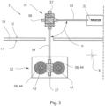
- Figure 3 shows a further development of the previously described embodiment according to the Figures 1 and 2 , whereby the two versions differ in the design of the rail 40.
- the respective rail 40 has two spindles 42, wherein the spindles 42 are arranged on both sides of the respective second gear unit 32 with respect to the longitudinal axis X.
- the two spindles 42 of the respective rail are designed to run in opposite directions and each have a spindle nut 44, wherein both spindle nuts 44 are in direct operative contact with a component of the second gear part 32.
Landscapes
- Engineering & Computer Science (AREA)
- Aviation & Aerospace Engineering (AREA)
- Transportation (AREA)
- Mechanical Engineering (AREA)
- Seats For Vehicles (AREA)
Claims (19)
- Unité de réglage longitudinal de siège (2) comprenant :- une installation d'entrainement (22),- deux rails (40) ayant respectivement au moins une broche (42) et parallèles à l'axe longitudinal (X) en étant écartés l'un de l'autre et,- deux lignes d'entrainement (24), entrainées par l'installation d'entrainement (22),* chacune des lignes d'entrainement (24) a respectivement une première unité de transmission (31) et une seconde unité de transmission (32), la seconde unité de transmission (32) étant couplée par la première unité de transmission (31) à l'installation d'entrainement (22),* la seconde unité de transmission (32) de la ligne d'entrainement avant (24) respective pour générer un entrainement vers l'avant selon l'axe longitudinal (X) est couplée avec l'un des rails (40) unité caractérisée en ce que- la première unité de transmission (31) est reliée à l'installation d'entrainement (22) par un premier arbre (33) et la seconde unité de transmission (32) est reliée à la première unité de transmission (31) par un second arbre (34).
- Unité de réglage longitudinal de siège (2) selon la revendication 1, caractérisée en ce que
la première unité de transmission (31) et/ou la seconde unité de transmission (32) ont une transmission à vis. - Unité de réglage longitudinal de siège (2) selon la revendication 1 ou 2,
caractérisée en ce que
la première unité de transmission (31) et la seconde unité de transmission (32) ont le même rapport de démultiplication et la même denture. - Unité de réglage longitudinal de siège (2) selon l'une des revendications précédentes,
caractérisée en ce quele premier arbre (33) fait un angle (α) par rapport au second arbre (34) en étant décalé et,le premier arbre (33) et le second arbre (34) sont transversaux à l'axe longitudinal (X). - Unité de réglage longitudinal de siège (2) selon la revendication 4, caractérisée en ce que
l'angle (α) est de 90° ± 15°. - Unité de réglage longitudinal de siège (2) selon l'une des revendications précédentes,
caractérisée en ce que
le premier arbre (33) des deux lignes d'entrainement (24) est en une seule pièce. - Unité de réglage longitudinal de siège (2) selon l'une des revendications précédentes,
caractérisée en ce que
l'installation d'entrainement (22) est entre les deux lignes d'entrainement (24). - Unité de réglage longitudinal de siège (2) selon l'une des revendications précédentes,
caractérisée en ce que
le premier arbre (33) et/ou le second arbre (34) sont des arbres flexibles. - Unité de réglage longitudinal de siège (2) selon l'une des revendications précédentes,
caractérisée en ce que
la seconde unité de transmission (32) est couplée à la broche (42) chaque fois par un écrou de broche (44). - Unité de réglage longitudinal de siège (2) selon l'une des revendications précédentes,
caractérisée en ce que
la première unité de transmission (31) et la seconde unité de transmission (32) d'au moins une ligne d'entrainement avant (24) sont dans une pièce de support (45). - Unité de réglage longitudinal de siège (2) selon la revendication 10, caractérisée en ce que
la pièce de support (45) a au moins un premier segment partiel (46) et un second segment partiel (47),
* la première unité de transmission (31) étant dans le premier segment partiel (46) et la seconde unité de transmission (32) étant dans le second segment partiel (47). - Unité de réglage longitudinal de siège (2) selon l'une des revendications précédentes,
caractérisée en ce que
le premier segment partiel (46) et le second segment partiel (47) sont couplés de manière amovible par des moyens de liaison (48). - Unité de réglage longitudinal de siège (2) selon l'une des revendications précédentes,
caractérisée en ce que
le second arbre (34) est en deux parties et les moyens de liaison (48) peuvent coupler les deux segments d'arbre. - Unité de réglage longitudinal de siège (2) selon l'une des revendications précédentes,
caractérisée en ce que
le rail respectif (40) comprend deux broches (42). - Unité de réglage longitudinal de siège (2) selon la revendication 14, caractérisée en ce que
les deux broches (42) sont de part et d'autre de la seconde unité de transmission (32) respective et les broches (42) sont en sens opposé. - Dispositif de siège (1), notamment dispositif de siège (1) de véhicule automobile comprenant :- un fond de cabine (10) avec un côté passager (12) et un dessous (11), et- une unité de réglage longitudinal de siège (2), selon l'une des revendications précédentes,- le plancher (10) ayant dans l'axe longitudinal (X) au moins deux passages (15) parallèles et écartés reliant le côté passager (12) et le dessous (11) et,- les rails (40) et les secondes unités de transmission (32) sont sur le dessous (11) et,- le côté passager (12) porte les premières unités de transmission (31) et installation d'entrainement (22).
- Dispositif de siège (1) selon la revendication 16,
caractérisé en ce que
la pièce de support (45) traverse les passages (15). - Dispositif de siège (1) selon l'une des revendications précédentes, caractérisé en ce que
le premier segment partiel (46) vient du côté passager (12) dans le passage respectif (15). - Véhicule automobile équipé d'une unité de réglage longitudinal de siège (2) selon l'une des revendications 1 à 15 ou d'un dispositif de siège (1) selon l'une des revendications 16 à 18.
Priority Applications (5)
| Application Number | Priority Date | Filing Date | Title |
|---|---|---|---|
| EP21160795.7A EP4052959B1 (fr) | 2021-03-04 | 2021-03-04 | Unité de réglage de la longueur du siège, agencement de siège et véhicule automobile |
| ES21160795T ES2997975T3 (en) | 2021-03-04 | 2021-03-04 | Seat length adjustment unit, seat assembly and motor vehicle |
| CN202210206060.3A CN115009115B (zh) | 2021-03-04 | 2022-02-28 | 座椅纵向调节单元、座椅装置和机动车辆 |
| KR1020220026887A KR102738962B1 (ko) | 2021-03-04 | 2022-03-02 | 시트 조절 유닛, 시트 배열체 및 자동차 |
| US17/685,801 US12240359B2 (en) | 2021-03-04 | 2022-03-03 | Longitudinal seat adjustment unit, seat arrangement, and motor vehicle |
Applications Claiming Priority (1)
| Application Number | Priority Date | Filing Date | Title |
|---|---|---|---|
| EP21160795.7A EP4052959B1 (fr) | 2021-03-04 | 2021-03-04 | Unité de réglage de la longueur du siège, agencement de siège et véhicule automobile |
Publications (2)
| Publication Number | Publication Date |
|---|---|
| EP4052959A1 EP4052959A1 (fr) | 2022-09-07 |
| EP4052959B1 true EP4052959B1 (fr) | 2024-09-25 |
Family
ID=74859197
Family Applications (1)
| Application Number | Title | Priority Date | Filing Date |
|---|---|---|---|
| EP21160795.7A Active EP4052959B1 (fr) | 2021-03-04 | 2021-03-04 | Unité de réglage de la longueur du siège, agencement de siège et véhicule automobile |
Country Status (5)
| Country | Link |
|---|---|
| US (1) | US12240359B2 (fr) |
| EP (1) | EP4052959B1 (fr) |
| KR (1) | KR102738962B1 (fr) |
| CN (1) | CN115009115B (fr) |
| ES (1) | ES2997975T3 (fr) |
Families Citing this family (6)
| Publication number | Priority date | Publication date | Assignee | Title |
|---|---|---|---|---|
| KR102497964B1 (ko) * | 2021-06-21 | 2023-02-10 | 대원산업 주식회사 | 차동 동력 수평 수직 전환형 액츄에이터 모듈 |
| KR102571433B1 (ko) | 2021-07-13 | 2023-08-28 | 현대트랜시스 주식회사 | 전동식 시트레일 이송장치 |
| WO2024072111A1 (fr) | 2022-09-30 | 2024-04-04 | (주)옵토레인 | Procédé d'analyse pcr en temps réel numérique |
| US20260098292A1 (en) | 2022-09-30 | 2026-04-09 | Optolane Technologies Inc. | Digital real-time pcr analysis method |
| US12022949B2 (en) * | 2022-10-13 | 2024-07-02 | Hidden Lake 822, Llc | Drive motor-linear actuator system for powered lift or powered reclining chairs |
| CN116279005A (zh) * | 2023-04-06 | 2023-06-23 | 无锡威孚智行座椅有限公司 | 汽车滑轨结构 |
Family Cites Families (26)
| Publication number | Priority date | Publication date | Assignee | Title |
|---|---|---|---|---|
| US1806014A (en) * | 1929-01-07 | 1931-05-19 | Flintermann Gerhard | Adjustable seat for vehicles |
| JPS62127545A (ja) | 1985-11-26 | 1987-06-09 | Aisin Seiki Co Ltd | パワ−シ−ト用駆動装置 |
| JP3089680B2 (ja) | 1991-03-20 | 2000-09-18 | アイシン精機株式会社 | 車両用シートスライド装置 |
| US6105920A (en) * | 1996-06-06 | 2000-08-22 | Lear Corporation | Vehicle power seat adjuster with hidden floor mount |
| US5791622A (en) * | 1996-07-02 | 1998-08-11 | Lear Corporation | Vehicle power seat adjuster with flex cable guides |
| DE19642655C1 (de) | 1996-10-16 | 1998-06-10 | Continental Ag | Verstärkungslage für den Gürtel eines Fahrzeugreifens |
| JPH10138805A (ja) * | 1996-11-12 | 1998-05-26 | Ikeda Bussan Co Ltd | 自動車用シートのパワースライド装置 |
| JP3131394B2 (ja) * | 1996-11-12 | 2001-01-31 | 池田物産株式会社 | 自動車用シートのパワースライド装置 |
| JP3202633B2 (ja) * | 1997-02-07 | 2001-08-27 | ジョンソン コントロールズ オートモーティブ システムズ株式会社 | 自動車シートのパワースライド装置 |
| DE19815283C2 (de) | 1998-04-06 | 2000-07-13 | Brose Fahrzeugteile | Spindelantrieb für Verstelleinrichtungen in Kraftfahrzeugen |
| DE19956614A1 (de) * | 1999-11-25 | 2001-05-31 | Hammerstein Gmbh C Rob | Verstellvorrichtung für einen Fahrzeugsitz mit einer spindel und einer zugeordneten Spindelmutter |
| JP2005059771A (ja) * | 2003-08-18 | 2005-03-10 | Honda Motor Co Ltd | 車両用シートおよび車両 |
| EP1571034B1 (fr) * | 2004-03-04 | 2007-10-17 | KEIPER GmbH & Co. KG | Dispositif de réglage longitudinal pour un siège de véhicule |
| DE102004013009B4 (de) | 2004-03-16 | 2008-03-20 | Ims Gear Gmbh | Antrieb für eine Verstelleinrichtung innerhalb eines Fahrzeuges, insbesondere eine Sitzverstelleinrichtung innerhalb eines Kraftfahrzeuges und Verfahren zur Herstellung eines solchen Antriebs |
| KR100803305B1 (ko) * | 2006-10-31 | 2008-02-13 | 현대자동차주식회사 | 차량의 시트 슬라이딩 장치 |
| DE102006052936A1 (de) | 2006-11-08 | 2008-05-15 | Ims Gear Gmbh | Längsverstelleinheit für Sitze, insbesondere in Kraftfahrzeugen |
| JP5337709B2 (ja) * | 2007-01-04 | 2013-11-06 | ジョンソン コントロールズ テクノロジー カンパニー | 動力化されたトラックシステム用のトランスミッション |
| JP5446373B2 (ja) * | 2009-03-27 | 2014-03-19 | アイシン精機株式会社 | 駆動伝達装置及び車両用シートスライド装置 |
| JP5348069B2 (ja) * | 2010-05-21 | 2013-11-20 | トヨタ車体株式会社 | デッキボードの支持構造 |
| US9688164B2 (en) * | 2015-08-25 | 2017-06-27 | Tesla, Inc. | Movable vehicle seat with monopost |
| DE102016225053B4 (de) * | 2016-12-14 | 2025-07-10 | Brose Fahrzeugteile SE & Co. Kommanditgesellschaft, Coburg | Verstelleinrichtung für die Längsverstellung eines Fahrzeugsitzes |
| DE102017117534A1 (de) * | 2017-08-02 | 2019-02-07 | Brose Fahrzeugteile Gmbh & Co. Kg, Coburg | Sitzschienenmodul für einen Fahrzeugsitz zur Fahrzeugsitzverzögerung im Crashfall |
| JP2019192157A (ja) | 2018-04-27 | 2019-10-31 | 株式会社ブリヂストン | 車両の運行管理装置 |
| CN115158117B (zh) * | 2018-09-14 | 2024-03-15 | 丰田纺织精工株式会社 | 座椅滑动装置 |
| US11760233B2 (en) * | 2019-02-20 | 2023-09-19 | Fisher & Company, Incorporated | Ultra-compact power length adjuster with anti-back drive capability and pinion-rack output for a vehicle seat |
| DE102020130226B4 (de) * | 2020-09-11 | 2024-08-08 | Adient Us Llc | Längseinsteller, Fahrzeugsitz |
-
2021
- 2021-03-04 EP EP21160795.7A patent/EP4052959B1/fr active Active
- 2021-03-04 ES ES21160795T patent/ES2997975T3/es active Active
-
2022
- 2022-02-28 CN CN202210206060.3A patent/CN115009115B/zh active Active
- 2022-03-02 KR KR1020220026887A patent/KR102738962B1/ko active Active
- 2022-03-03 US US17/685,801 patent/US12240359B2/en active Active
Also Published As
| Publication number | Publication date |
|---|---|
| CN115009115A (zh) | 2022-09-06 |
| KR102738962B1 (ko) | 2024-12-05 |
| KR20220125179A (ko) | 2022-09-14 |
| US20220281357A1 (en) | 2022-09-08 |
| CN115009115B (zh) | 2024-05-03 |
| EP4052959A1 (fr) | 2022-09-07 |
| US12240359B2 (en) | 2025-03-04 |
| ES2997975T3 (en) | 2025-02-18 |
Similar Documents
| Publication | Publication Date | Title |
|---|---|---|
| EP4052959A1 (fr) | Unité de réglage de la longueur du siège, agencement de siège et véhicule automobile | |
| EP1365939B1 (fr) | Dispositif de reglage longitudinal d'un siege, en particulier dans une automobile | |
| EP1791717B1 (fr) | Dispositif de reglage, en particulier pour le siege d'un vehicule a moteur | |
| DE102015223485B4 (de) | Höheneinsteller für einen fahrzeugsitz, fahrzeugsitz | |
| WO2003004304A1 (fr) | Systeme destine au deplacement et au blocage d'une unite modulaire pouvant etre reliee a une structure, par ex. au fond d'un moyen de circulation ou de transport | |
| EP4100279B1 (fr) | Dispositif de réglage longitudinal et siège de véhicule | |
| DE19836425A1 (de) | Sitzgestell eines verstellbaren Fahrzeugsitzes | |
| DE2844647C2 (de) | Längsverstellvorrichtung für einen Fahrzeugsitz, insbesondere einen Kraftfahrzeugsitz | |
| DE102018214546A1 (de) | Elektrisch verstellbare Steer-by-Wire Lenksäule und Kraftfahrzeug | |
| WO2013017632A2 (fr) | Mécanisme de commande pour une glissière d'un système de réglage longitudinal d'un siège de véhicule automobile | |
| DE102019122928B3 (de) | Längseinsteller und fahrzeugsitz | |
| DE102019125196A1 (de) | Längseinsteller, fahrzeugsitz | |
| DE102021100886B4 (de) | Längseinsteller und fahrzeugsitz | |
| DE102019206543A1 (de) | Kopfstützenanordnung mit einem Antrieb zur horizontalen Verstellung eines Kopfstützenkastens für einen Kraftfahrzeugsitz | |
| DE102012203553A1 (de) | Übersetzungsgetriebe | |
| WO2018068778A1 (fr) | Transmission ainsi qu'appuie-tête pourvu d'au moins un entraînement électrique, comprenant une transmission | |
| DE102018216770B4 (de) | Baugruppe mit einer mit einer Bodenbaugruppe zu verbindenden Führungsschiene | |
| DE102020202523A1 (de) | Verstelleinrichtung für einen Fahrzeugsitz | |
| EP4204255B1 (fr) | Système de réglage en longueur, procédé de montage d'un système de réglage en longueur et siège de véhicule | |
| EP1571034A2 (fr) | Dispositif de réglage longitudinal pour un siège de véhicule | |
| EP0128111B1 (fr) | Mécanisme de déplacement longitudinal pour sièges de véhicules ayant un dispositif de déplacement actionné par moteur et un guidage longitudinal | |
| DE10045806B4 (de) | Sitzlängsverstellung für einen Kraftfahrzeugsitz | |
| DE102010038009A1 (de) | Sitzgestell, Sitz und Kraftfahrzeug | |
| DE102021207990A1 (de) | Lenksäule mit einer schwenkbaren Aufnahme für eine Lenkhandhabe | |
| DE102017102294B4 (de) | Verstellvorrichtung für einen Fahrzeugsitz sowie Fahrzeugsitz mit der Verstellvorrichtung |
Legal Events
| Date | Code | Title | Description |
|---|---|---|---|
| PUAI | Public reference made under article 153(3) epc to a published international application that has entered the european phase |
Free format text: ORIGINAL CODE: 0009012 |
|
| STAA | Information on the status of an ep patent application or granted ep patent |
Free format text: STATUS: THE APPLICATION HAS BEEN PUBLISHED |
|
| AK | Designated contracting states |
Kind code of ref document: A1 Designated state(s): AL AT BE BG CH CY CZ DE DK EE ES FI FR GB GR HR HU IE IS IT LI LT LU LV MC MK MT NL NO PL PT RO RS SE SI SK SM TR |
|
| STAA | Information on the status of an ep patent application or granted ep patent |
Free format text: STATUS: REQUEST FOR EXAMINATION WAS MADE |
|
| 17P | Request for examination filed |
Effective date: 20230302 |
|
| RBV | Designated contracting states (corrected) |
Designated state(s): AL AT BE BG CH CY CZ DE DK EE ES FI FR GB GR HR HU IE IS IT LI LT LU LV MC MK MT NL NO PL PT RO RS SE SI SK SM TR |
|
| P01 | Opt-out of the competence of the unified patent court (upc) registered |
Effective date: 20230323 |
|
| RIC1 | Information provided on ipc code assigned before grant |
Ipc: B60N 2/06 20060101AFI20240327BHEP |
|
| GRAP | Despatch of communication of intention to grant a patent |
Free format text: ORIGINAL CODE: EPIDOSNIGR1 |
|
| STAA | Information on the status of an ep patent application or granted ep patent |
Free format text: STATUS: GRANT OF PATENT IS INTENDED |
|
| INTG | Intention to grant announced |
Effective date: 20240627 |
|
| GRAS | Grant fee paid |
Free format text: ORIGINAL CODE: EPIDOSNIGR3 |
|
| GRAA | (expected) grant |
Free format text: ORIGINAL CODE: 0009210 |
|
| STAA | Information on the status of an ep patent application or granted ep patent |
Free format text: STATUS: THE PATENT HAS BEEN GRANTED |
|
| AK | Designated contracting states |
Kind code of ref document: B1 Designated state(s): AL AT BE BG CH CY CZ DE DK EE ES FI FR GB GR HR HU IE IS IT LI LT LU LV MC MK MT NL NO PL PT RO RS SE SI SK SM TR |
|
| REG | Reference to a national code |
Ref country code: GB Ref legal event code: FG4D Free format text: NOT ENGLISH |
|
| REG | Reference to a national code |
Ref country code: CH Ref legal event code: EP |
|
| REG | Reference to a national code |
Ref country code: DE Ref legal event code: R096 Ref document number: 502021005220 Country of ref document: DE |
|
| REG | Reference to a national code |
Ref country code: IE Ref legal event code: FG4D Free format text: LANGUAGE OF EP DOCUMENT: GERMAN |
|
| REG | Reference to a national code |
Ref country code: LT Ref legal event code: MG9D |
|
| PG25 | Lapsed in a contracting state [announced via postgrant information from national office to epo] |
Ref country code: NO Free format text: LAPSE BECAUSE OF FAILURE TO SUBMIT A TRANSLATION OF THE DESCRIPTION OR TO PAY THE FEE WITHIN THE PRESCRIBED TIME-LIMIT Effective date: 20241225 |
|
| PG25 | Lapsed in a contracting state [announced via postgrant information from national office to epo] |
Ref country code: GR Free format text: LAPSE BECAUSE OF FAILURE TO SUBMIT A TRANSLATION OF THE DESCRIPTION OR TO PAY THE FEE WITHIN THE PRESCRIBED TIME-LIMIT Effective date: 20241226 Ref country code: FI Free format text: LAPSE BECAUSE OF FAILURE TO SUBMIT A TRANSLATION OF THE DESCRIPTION OR TO PAY THE FEE WITHIN THE PRESCRIBED TIME-LIMIT Effective date: 20240925 |
|
| PG25 | Lapsed in a contracting state [announced via postgrant information from national office to epo] |
Ref country code: BG Free format text: LAPSE BECAUSE OF FAILURE TO SUBMIT A TRANSLATION OF THE DESCRIPTION OR TO PAY THE FEE WITHIN THE PRESCRIBED TIME-LIMIT Effective date: 20240925 |
|
| PG25 | Lapsed in a contracting state [announced via postgrant information from national office to epo] |
Ref country code: LV Free format text: LAPSE BECAUSE OF FAILURE TO SUBMIT A TRANSLATION OF THE DESCRIPTION OR TO PAY THE FEE WITHIN THE PRESCRIBED TIME-LIMIT Effective date: 20240925 |
|
| PG25 | Lapsed in a contracting state [announced via postgrant information from national office to epo] |
Ref country code: RS Free format text: LAPSE BECAUSE OF FAILURE TO SUBMIT A TRANSLATION OF THE DESCRIPTION OR TO PAY THE FEE WITHIN THE PRESCRIBED TIME-LIMIT Effective date: 20241225 |
|
| REG | Reference to a national code |
Ref country code: NL Ref legal event code: MP Effective date: 20240925 |
|
| PG25 | Lapsed in a contracting state [announced via postgrant information from national office to epo] |
Ref country code: RS Free format text: LAPSE BECAUSE OF FAILURE TO SUBMIT A TRANSLATION OF THE DESCRIPTION OR TO PAY THE FEE WITHIN THE PRESCRIBED TIME-LIMIT Effective date: 20241225 Ref country code: NO Free format text: LAPSE BECAUSE OF FAILURE TO SUBMIT A TRANSLATION OF THE DESCRIPTION OR TO PAY THE FEE WITHIN THE PRESCRIBED TIME-LIMIT Effective date: 20241225 Ref country code: LV Free format text: LAPSE BECAUSE OF FAILURE TO SUBMIT A TRANSLATION OF THE DESCRIPTION OR TO PAY THE FEE WITHIN THE PRESCRIBED TIME-LIMIT Effective date: 20240925 Ref country code: GR Free format text: LAPSE BECAUSE OF FAILURE TO SUBMIT A TRANSLATION OF THE DESCRIPTION OR TO PAY THE FEE WITHIN THE PRESCRIBED TIME-LIMIT Effective date: 20241226 Ref country code: FI Free format text: LAPSE BECAUSE OF FAILURE TO SUBMIT A TRANSLATION OF THE DESCRIPTION OR TO PAY THE FEE WITHIN THE PRESCRIBED TIME-LIMIT Effective date: 20240925 Ref country code: BG Free format text: LAPSE BECAUSE OF FAILURE TO SUBMIT A TRANSLATION OF THE DESCRIPTION OR TO PAY THE FEE WITHIN THE PRESCRIBED TIME-LIMIT Effective date: 20240925 |
|
| PG25 | Lapsed in a contracting state [announced via postgrant information from national office to epo] |
Ref country code: NL Free format text: LAPSE BECAUSE OF FAILURE TO SUBMIT A TRANSLATION OF THE DESCRIPTION OR TO PAY THE FEE WITHIN THE PRESCRIBED TIME-LIMIT Effective date: 20240925 |
|
| REG | Reference to a national code |
Ref country code: ES Ref legal event code: FG2A Ref document number: 2997975 Country of ref document: ES Kind code of ref document: T3 Effective date: 20250218 |
|
| PG25 | Lapsed in a contracting state [announced via postgrant information from national office to epo] |
Ref country code: IS Free format text: LAPSE BECAUSE OF FAILURE TO SUBMIT A TRANSLATION OF THE DESCRIPTION OR TO PAY THE FEE WITHIN THE PRESCRIBED TIME-LIMIT Effective date: 20250125 Ref country code: PT Free format text: LAPSE BECAUSE OF FAILURE TO SUBMIT A TRANSLATION OF THE DESCRIPTION OR TO PAY THE FEE WITHIN THE PRESCRIBED TIME-LIMIT Effective date: 20250127 |
|
| PG25 | Lapsed in a contracting state [announced via postgrant information from national office to epo] |
Ref country code: RO Free format text: LAPSE BECAUSE OF FAILURE TO SUBMIT A TRANSLATION OF THE DESCRIPTION OR TO PAY THE FEE WITHIN THE PRESCRIBED TIME-LIMIT Effective date: 20240925 Ref country code: SM Free format text: LAPSE BECAUSE OF FAILURE TO SUBMIT A TRANSLATION OF THE DESCRIPTION OR TO PAY THE FEE WITHIN THE PRESCRIBED TIME-LIMIT Effective date: 20240925 |
|
| PG25 | Lapsed in a contracting state [announced via postgrant information from national office to epo] |
Ref country code: EE Free format text: LAPSE BECAUSE OF FAILURE TO SUBMIT A TRANSLATION OF THE DESCRIPTION OR TO PAY THE FEE WITHIN THE PRESCRIBED TIME-LIMIT Effective date: 20240925 |
|
| PGFP | Annual fee paid to national office [announced via postgrant information from national office to epo] |
Ref country code: AT Payment date: 20250417 Year of fee payment: 5 |
|
| PG25 | Lapsed in a contracting state [announced via postgrant information from national office to epo] |
Ref country code: PL Free format text: LAPSE BECAUSE OF FAILURE TO SUBMIT A TRANSLATION OF THE DESCRIPTION OR TO PAY THE FEE WITHIN THE PRESCRIBED TIME-LIMIT Effective date: 20240925 Ref country code: CZ Free format text: LAPSE BECAUSE OF FAILURE TO SUBMIT A TRANSLATION OF THE DESCRIPTION OR TO PAY THE FEE WITHIN THE PRESCRIBED TIME-LIMIT Effective date: 20240925 |
|
| PG25 | Lapsed in a contracting state [announced via postgrant information from national office to epo] |
Ref country code: SK Free format text: LAPSE BECAUSE OF FAILURE TO SUBMIT A TRANSLATION OF THE DESCRIPTION OR TO PAY THE FEE WITHIN THE PRESCRIBED TIME-LIMIT Effective date: 20240925 |
|
| REG | Reference to a national code |
Ref country code: DE Ref legal event code: R097 Ref document number: 502021005220 Country of ref document: DE |
|
| PGFP | Annual fee paid to national office [announced via postgrant information from national office to epo] |
Ref country code: DE Payment date: 20250429 Year of fee payment: 5 |
|
| PG25 | Lapsed in a contracting state [announced via postgrant information from national office to epo] |
Ref country code: DK Free format text: LAPSE BECAUSE OF FAILURE TO SUBMIT A TRANSLATION OF THE DESCRIPTION OR TO PAY THE FEE WITHIN THE PRESCRIBED TIME-LIMIT Effective date: 20240925 |
|
| PGFP | Annual fee paid to national office [announced via postgrant information from national office to epo] |
Ref country code: ES Payment date: 20250416 Year of fee payment: 5 |
|
| PGFP | Annual fee paid to national office [announced via postgrant information from national office to epo] |
Ref country code: IT Payment date: 20250331 Year of fee payment: 5 |
|
| PLBE | No opposition filed within time limit |
Free format text: ORIGINAL CODE: 0009261 |
|
| STAA | Information on the status of an ep patent application or granted ep patent |
Free format text: STATUS: NO OPPOSITION FILED WITHIN TIME LIMIT |
|
| 26N | No opposition filed |
Effective date: 20250626 |
|
| PG25 | Lapsed in a contracting state [announced via postgrant information from national office to epo] |
Ref country code: SE Free format text: LAPSE BECAUSE OF FAILURE TO SUBMIT A TRANSLATION OF THE DESCRIPTION OR TO PAY THE FEE WITHIN THE PRESCRIBED TIME-LIMIT Effective date: 20240925 |
|
| PG25 | Lapsed in a contracting state [announced via postgrant information from national office to epo] |
Ref country code: MC Free format text: LAPSE BECAUSE OF FAILURE TO SUBMIT A TRANSLATION OF THE DESCRIPTION OR TO PAY THE FEE WITHIN THE PRESCRIBED TIME-LIMIT Effective date: 20240925 |
|
| REG | Reference to a national code |
Ref country code: CH Ref legal event code: H13 Free format text: ST27 STATUS EVENT CODE: U-0-0-H10-H13 (AS PROVIDED BY THE NATIONAL OFFICE) Effective date: 20251023 |
|
| PG25 | Lapsed in a contracting state [announced via postgrant information from national office to epo] |
Ref country code: LU Free format text: LAPSE BECAUSE OF NON-PAYMENT OF DUE FEES Effective date: 20250304 |
|
| GBPC | Gb: european patent ceased through non-payment of renewal fee |
Effective date: 20250304 |
|
| REG | Reference to a national code |
Ref country code: BE Ref legal event code: MM Effective date: 20250331 |
|
| PG25 | Lapsed in a contracting state [announced via postgrant information from national office to epo] |
Ref country code: GB Free format text: LAPSE BECAUSE OF NON-PAYMENT OF DUE FEES Effective date: 20250304 |
|
| PG25 | Lapsed in a contracting state [announced via postgrant information from national office to epo] |
Ref country code: HR Free format text: LAPSE BECAUSE OF FAILURE TO SUBMIT A TRANSLATION OF THE DESCRIPTION OR TO PAY THE FEE WITHIN THE PRESCRIBED TIME-LIMIT Effective date: 20240925 |
|
| PG25 | Lapsed in a contracting state [announced via postgrant information from national office to epo] |
Ref country code: BE Free format text: LAPSE BECAUSE OF NON-PAYMENT OF DUE FEES Effective date: 20250331 |
|
| PG25 | Lapsed in a contracting state [announced via postgrant information from national office to epo] |
Ref country code: CH Free format text: LAPSE BECAUSE OF NON-PAYMENT OF DUE FEES Effective date: 20250331 |
|
| PG25 | Lapsed in a contracting state [announced via postgrant information from national office to epo] |
Ref country code: IE Free format text: LAPSE BECAUSE OF NON-PAYMENT OF DUE FEES Effective date: 20250304 |
|
| PGFP | Annual fee paid to national office [announced via postgrant information from national office to epo] |
Ref country code: FR Payment date: 20260324 Year of fee payment: 6 |