EP4204255B1 - Système de réglage en longueur, procédé de montage d'un système de réglage en longueur et siège de véhicule - Google Patents
Système de réglage en longueur, procédé de montage d'un système de réglage en longueur et siège de véhicule Download PDFInfo
- Publication number
- EP4204255B1 EP4204255B1 EP21801998.2A EP21801998A EP4204255B1 EP 4204255 B1 EP4204255 B1 EP 4204255B1 EP 21801998 A EP21801998 A EP 21801998A EP 4204255 B1 EP4204255 B1 EP 4204255B1
- Authority
- EP
- European Patent Office
- Prior art keywords
- rail
- opening
- fixing element
- spindle
- longitudinal
- Prior art date
- Legal status (The legal status is an assumption and is not a legal conclusion. Google has not performed a legal analysis and makes no representation as to the accuracy of the status listed.)
- Active
Links
Images

Classifications
-
- B—PERFORMING OPERATIONS; TRANSPORTING
- B60—VEHICLES IN GENERAL
- B60N—SEATS SPECIALLY ADAPTED FOR VEHICLES; VEHICLE PASSENGER ACCOMMODATION NOT OTHERWISE PROVIDED FOR
- B60N2/00—Seats specially adapted for vehicles; Arrangement or mounting of seats in vehicles
- B60N2/02—Seats specially adapted for vehicles; Arrangement or mounting of seats in vehicles the seat or part thereof being movable, e.g. adjustable
- B60N2/0224—Non-manual adjustments, e.g. with electrical operation
- B60N2/02246—Electric motors therefor
-
- B—PERFORMING OPERATIONS; TRANSPORTING
- B60—VEHICLES IN GENERAL
- B60N—SEATS SPECIALLY ADAPTED FOR VEHICLES; VEHICLE PASSENGER ACCOMMODATION NOT OTHERWISE PROVIDED FOR
- B60N2/00—Seats specially adapted for vehicles; Arrangement or mounting of seats in vehicles
- B60N2/02—Seats specially adapted for vehicles; Arrangement or mounting of seats in vehicles the seat or part thereof being movable, e.g. adjustable
- B60N2/04—Seats specially adapted for vehicles; Arrangement or mounting of seats in vehicles the seat or part thereof being movable, e.g. adjustable the whole seat being movable
- B60N2/06—Seats specially adapted for vehicles; Arrangement or mounting of seats in vehicles the seat or part thereof being movable, e.g. adjustable the whole seat being movable slidable
- B60N2/067—Seats specially adapted for vehicles; Arrangement or mounting of seats in vehicles the seat or part thereof being movable, e.g. adjustable the whole seat being movable slidable by linear actuators, e.g. linear screw mechanisms
-
- B—PERFORMING OPERATIONS; TRANSPORTING
- B60—VEHICLES IN GENERAL
- B60N—SEATS SPECIALLY ADAPTED FOR VEHICLES; VEHICLE PASSENGER ACCOMMODATION NOT OTHERWISE PROVIDED FOR
- B60N2/00—Seats specially adapted for vehicles; Arrangement or mounting of seats in vehicles
- B60N2/68—Seat frames
- B60N2/682—Joining means
-
- F—MECHANICAL ENGINEERING; LIGHTING; HEATING; WEAPONS; BLASTING
- F16—ENGINEERING ELEMENTS AND UNITS; GENERAL MEASURES FOR PRODUCING AND MAINTAINING EFFECTIVE FUNCTIONING OF MACHINES OR INSTALLATIONS; THERMAL INSULATION IN GENERAL
- F16B—DEVICES FOR FASTENING OR SECURING CONSTRUCTIONAL ELEMENTS OR MACHINE PARTS TOGETHER, e.g. NAILS, BOLTS, CIRCLIPS, CLAMPS, CLIPS OR WEDGES; JOINTS OR JOINTING
- F16B35/00—Screw-bolts; Stay-bolts; Screw-threaded studs; Screws; Set screws
- F16B35/04—Screw-bolts; Stay-bolts; Screw-threaded studs; Screws; Set screws with specially-shaped head or shaft in order to fix the bolt on or in an object
- F16B35/041—Specially-shaped shafts
- F16B35/048—Specially-shaped necks
-
- B—PERFORMING OPERATIONS; TRANSPORTING
- B60—VEHICLES IN GENERAL
- B60Y—INDEXING SCHEME RELATING TO ASPECTS CROSS-CUTTING VEHICLE TECHNOLOGY
- B60Y2304/00—Optimising design; Manufacturing; Testing
- B60Y2304/07—Facilitating assembling or mounting
- B60Y2304/074—Facilitating assembling or mounting by improved accessibility
-
- F—MECHANICAL ENGINEERING; LIGHTING; HEATING; WEAPONS; BLASTING
- F16—ENGINEERING ELEMENTS AND UNITS; GENERAL MEASURES FOR PRODUCING AND MAINTAINING EFFECTIVE FUNCTIONING OF MACHINES OR INSTALLATIONS; THERMAL INSULATION IN GENERAL
- F16B—DEVICES FOR FASTENING OR SECURING CONSTRUCTIONAL ELEMENTS OR MACHINE PARTS TOGETHER, e.g. NAILS, BOLTS, CIRCLIPS, CLAMPS, CLIPS OR WEDGES; JOINTS OR JOINTING
- F16B37/00—Nuts or like thread-engaging members
- F16B37/04—Devices for fastening nuts to surfaces, e.g. sheets, plates
- F16B37/06—Devices for fastening nuts to surfaces, e.g. sheets, plates by means of welding or riveting
- F16B37/062—Devices for fastening nuts to surfaces, e.g. sheets, plates by means of welding or riveting by means of riveting
- F16B37/068—Devices for fastening nuts to surfaces, e.g. sheets, plates by means of welding or riveting by means of riveting by deforming the material of the support, e.g. the sheet or plate
-
- F—MECHANICAL ENGINEERING; LIGHTING; HEATING; WEAPONS; BLASTING
- F16—ENGINEERING ELEMENTS AND UNITS; GENERAL MEASURES FOR PRODUCING AND MAINTAINING EFFECTIVE FUNCTIONING OF MACHINES OR INSTALLATIONS; THERMAL INSULATION IN GENERAL
- F16B—DEVICES FOR FASTENING OR SECURING CONSTRUCTIONAL ELEMENTS OR MACHINE PARTS TOGETHER, e.g. NAILS, BOLTS, CIRCLIPS, CLAMPS, CLIPS OR WEDGES; JOINTS OR JOINTING
- F16B7/00—Connections of rods or tubes, e.g. of non-circular section, mutually, including resilient connections
- F16B7/10—Telescoping systems
Definitions
- the invention relates to a longitudinal adjuster, having at least one pair of rails, which is formed from a first rail and a second rail, wherein the first rail and the second rail are displaceable relative to one another, in particular in a longitudinal direction, wherein the first rail and the second rail mutually engage around one another to form an inner channel, wherein a spindle nut connected to the second rail and a spindle operatively connected to the spindle nut are arranged in the inner channel, wherein a spindle gear that can be driven by means of a motor and interacts with the spindle is arranged on the first rail, wherein the spindle nut is fixed to the second rail by means of a first fixing element and a second fixing element.
- the invention further relates to a method for assembling such a longitudinal adjuster and to a vehicle seat.
- a generic longitudinal adjuster for a vehicle seat having at least one pair of rails, which is formed from a first seat rail and a second seat rail which is displaceable in the longitudinal direction relative to the first seat rail, wherein the seat rails alternately engage around one another to form an inner channel, wherein a spindle nut mounted on the second seat rail and a spindle operatively connected to the spindle nut are arranged in the inner channel, wherein a gear which can be driven by a motor and interacts with the spindle is arranged at a front end of the first seat rail, wherein the spindle at a front end portion of the spindle in the gear and at a rear end portion of the spindle in a pivot bearing of the first seat rail.
- the spindle nut is fixed to the second rail by means of second fixing elements.
- the drive device for use with a motor vehicle seat sliding device comprises mating fixed and movable rail parts which can be moved between a forward position and a rearward position.
- the drive device comprises an elongated spindle, a spindle nut, a gear and a mounting device.
- the spindle defines a spindle axis and has a longitudinally extending spindle thread.
- the spindle nut can be securely fastened to a first rail part and has an internal thread which can engage the spindle thread.
- the gear can be mounted to a respective other rail part and selectively rotates the spindle about the spindle axis.
- the spindle of the drive device is provided with a spindle wheel which, when the drive device is mounted, extends outwards through spindle wheel openings in the movable rail part.
- a seat sliding device which has a system with a floating lead screw and a fixed nut.
- the nut is attached to the lower rail while the lead screw rotates through it so that the upper structure can move forward and backward.
- the nut is attached to the lower rail.
- a longitudinal adjuster comprising at least one pair of rails, which is formed from a second rail and a first rail which is displaceable in the longitudinal direction relative to the second rail, wherein the rails alternately engage around one another to form an inner channel, wherein a spindle nut mounted on the second rail and a spindle operatively connected to the spindle nut are arranged in the inner channel, wherein at one end of the first rail a driveable by means of a motor and a gear interacting with the spindle is arranged.
- the spindle nut is connected to the second rail by means of two crash bolts, with a circumferential gap being provided between each crash bolt and the second rail.
- an electric seat sliding device comprising a lower rail and an upper rail, the upper rail being displaceable relative to the lower rail, a spindle which is rotatably mounted on an inner side of the upper rail, and a nut element which is screwed onto the spindle and fixed to the lower rail by two bolts.
- the two bolts are arranged in two through holes formed in the lower rail, a movement clearance of the bolts being formed between the bolts and a respective inner peripheral surface of the through hole.
- a spindle bearing arrangement for a seat longitudinal adjustment mechanism which has a housing that can be fastened to a vehicle-side component or to a seat-side component using a fastening arrangement, wherein a spindle opening for passing a spindle through the housing along a spindle opening axis and wherein an internal thread in the housing in the region of its spindle opening is designed to engage in a spindle passed through in this way for adjusting the housing and the spindle relative to one another along the spindle opening axis.
- the spindle bearing arrangement provides that the internal thread is formed in a spindle nut and the spindle nut is adjustably mounted in the housing relative to the spindle opening axis.
- the invention is based on the object of improving a longitudinal adjuster of the type mentioned above, in particular to provide a longitudinal adjuster whose spindle nut can be easily positioned in the longitudinal adjuster and is easy to install. Furthermore, an underlying object is to provide a to provide a corresponding method for mounting a longitudinal adjuster and a corresponding vehicle seat.
- the longitudinal extension of the second rail preferably runs parallel to a longitudinal direction.
- the spindle nut is centered in a transverse direction by means of the two fixing elements.
- the spindle nut is centered in a transverse direction by means of the two Fixing elements preferably centered horizontally.
- the transverse direction is preferably in a horizontal plane, provided the vehicle is moving on a horizontal roadway.
- the first rail is preferably a seat rail that can be connected to a vehicle seat.
- the second rail is preferably a floor rail that can be connected to a vehicle structure.
- a possible structure of the spindle gear and its function are known, for example, from DE 10 2013 207 665 A1 known.
- the spindle can be mounted at a front end portion of the spindle in the spindle gear and/or at a rear end portion of the spindle in a pivot bearing of the first rail.
- the spindle nut can have a base body.
- the spindle nut can have a continuous threaded bore with an internal thread, in particular parallel to the longitudinal direction.
- the internal thread of the spindle nut can be operatively connected to an external thread of the spindle.
- the spindle is preferably screwed into the spindle nut.
- the spindle nut is preferably designed as a single piece.
- the two fixing elements can each have a shaft with an external thread and a head section.
- the two fixing elements preferably have a cone between the shaft and the head section in a transition region between the shaft and the head section.
- the first through-opening can have a substantially square cross-section with rounded corners.
- substantially square in the sense of the invention means that there is a slight difference of up to 1 millimeter in addition to a manufacturing tolerance, in particular up to 0.5 millimeters in addition to a manufacturing tolerances are possible.
- the length is preferably measured in the longitudinal direction and the width is preferably measured in the transverse direction.
- the second through-opening can have a substantially rectangular cross-section with rounded corners.
- substantially rectangular in the sense of the invention means that there is a difference of at least 1 millimeter in addition to a manufacturing tolerance, in particular of at least 1.5 millimeters in addition to a manufacturing tolerance, between a length and a width of the cross-section.
- the length is preferably measured in the longitudinal direction and the width is preferably measured in the transverse direction.
- the two through openings can have the same dimensions perpendicular to the longitudinal extension of the second rail, in particular in the transverse direction.
- a dimension of the first through opening parallel to the longitudinal extension of the second rail can be designed differently from a dimension of the second through opening parallel to the longitudinal extension of the second rail.
- Parallel to the longitudinal extension is to be understood in particular as in the direction of the longitudinal extension.
- the cone of the respective fixing element can have a diameter, in particular a maximum diameter, in a region adjacent to the respective head section, which is slightly larger than the dimension of the respective through opening perpendicular to the longitudinal extension, in particular in the transverse direction, of the second rail.
- the dimension of the second through-opening in the direction of the longitudinal extension of the second rail can be larger than a diameter, in particular a maximum diameter, of the cone of the second fixing element.
- a gap can be present in the longitudinal extension of the second rail in front of and/or behind the fixing element between the cone of the second fixing element and at least one edge section of the second through-opening.
- the second fixing element can have a clearance in the second through-opening parallel to the longitudinal extension of the second rail.
- the spindle nut can have a fixing opening for connection to the fixing elements.
- An inner diameter of the fixing opening is preferably adapted to an outer diameter of the fixing means.
- the fixing means can be a screw.
- the fixing means can be a bolt, in particular a threaded bolt.
- a buffer can be arranged between the spindle nut, in particular the base body of the spindle nut, and the second rail.
- the buffer is preferably flat.
- the buffer can be made of a plastic, in particular a rubber.
- the buffer can be made of metal.
- the buffer can be made of metal on the one hand and plastic or rubber on the other.
- One side of the buffer can be made of metal and the other side of the buffer can be made of plastic and/or rubber.
- the object is further achieved according to the invention by a method for assembling a longitudinal adjuster, in particular a longitudinal adjuster according to the above description, according to the features of claim 11.
- each of the two fixing elements has a cone in a transition region between a shaft and a head section.
- the two fixing elements can be designed identically.
- the spindle nut can be arranged on the second rail with a buffer in between.
- the buffer is preferably flat.
- the buffer can be made of a plastic, in particular a rubber.
- the buffer can be made of metal.
- the buffer can be made of metal on the one hand and plastic or rubber on the other.
- One side of the buffer can be made of metal and the other side of the buffer can be made of plastic and/or rubber.
- the first fixing element When the first fixing element is inserted into the first through-opening, the first fixing element can center itself in the first through-opening by means of the cone both parallel to a longitudinal extension of the second rail and perpendicular thereto, in particular in the transverse direction.
- the second fixing element When the second fixing element is inserted into the second through-opening, the second fixing element can center itself in the second through-opening by means of the cone, preferably exclusively perpendicular to the longitudinal extension of the second rail, in particular in the transverse direction.
- the object is further achieved according to the invention by a vehicle seat with a previously described longitudinal adjuster.
- the fastening of the spindle nut to the lower rail in the prior art is typically carried out with two to three screws.
- the mounting holes in the bottom rail for these screws are larger in diameter than the shaft of the screw in order to compensate for tolerances and to ensure that the screw head rests cleanly on the screw head.
- this requires active alignment of the spindle nut within the bottom rail using additional receptacles during the screwing process.
- the screws for fastening the spindle nut can have a cone between the screw head and the shaft of the respective screw.
- This cone is preferably designed in such a way that it achieves a centering of the screw in the transverse direction to a corresponding through-opening in the lower rail over all tolerances.
- the through-hole can be designed in such a way that the cone is only in contact with an edge area of the through-hole in the lower rail over a small contact area, in particular in a narrow section.
- This can be done using a rectangular hole which has approximately the same dimensions in the transverse direction of the lower rail as it does in the longitudinal direction.
- a second rectangular hole has a narrower dimension in the transverse direction of the lower rail and slightly larger in the longitudinal direction of the lower rail. This means that the second rectangular hole has play in the longitudinal direction in order to compensate for longitudinal tolerances.
- the small contact area means that the cone of the screw can deform the contact edge in the through-hole and the head surface of the screw comes into contact securely.
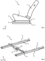
- a in Figure 1 A schematically illustrated vehicle seat 1 is described below using three spatial directions running perpendicular to one another.
- a longitudinal direction x runs largely horizontally in a vehicle seat 1 installed in the vehicle and preferably parallel to a vehicle longitudinal direction that corresponds to the usual direction of travel of the vehicle.
- a transverse direction y running perpendicular to the longitudinal direction x is also horizontally aligned in the vehicle and runs parallel to a vehicle transverse direction.
- a vertical direction z runs perpendicular to the longitudinal direction x and perpendicular to the transverse direction y.
- the vertical direction z runs parallel to the vehicle's vertical axis.
- the longitudinal direction x and the transverse direction y can define a horizontal plane.
- the position and direction information used refer to the viewing direction of an occupant sitting in the vehicle seat 1 in a normal sitting position, with the vehicle seat 1 installed in the vehicle, in a position of use suitable for transporting people with the backrest 4 upright and aligned in the direction of travel as usual.
- the vehicle seat 1 can, however, also be installed in a different orientation, for example transversely to the direction of travel.
- the in Fig. 1 The vehicle seat 1 shown for a motor vehicle has a seat part 2 and a backrest 4 whose inclination can be adjusted relative to the seat part 2.
- the inclination of the backrest 4 can be adjusted, for example, by means of a locking fitting or a gear fitting.
- the vehicle seat 1 is mounted on a longitudinal adjuster 10 for setting a longitudinal seat position.
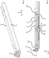
- Fig. 2 shows the longitudinal adjuster 10 according to the invention of the vehicle seat 1.
- the longitudinal adjuster 10 has at least one pair of rails, in this case two pairs of rails.
- Fig. 3 shows one of the rail pairs of the longitudinal adjuster 10.
- the rail pairs are each formed from a first rail 12, in particular for connection to a seat structure of the vehicle seat 1, and a second rail 14, in particular for connection to a vehicle structure.
- the rails 12, 14 of the rail pair are displaceable relative to one another in the longitudinal direction x and alternately engage around one another to form an inner channel 16.
- a spindle nut 30 mounted on the second rail 14, in this case arranged in a rotationally fixed manner, and a spindle 20 operatively connected to the spindle nut 30 are arranged in the inner channel 16.
- the spindle 20 extends along a spindle axis S parallel to the longitudinal direction x.
- a spindle gear 70 which can be driven by a motor 80 and drives the spindle 20 is arranged at a front end of the first rail 12.
- the motor 80 is mounted on a
- the motor carrier 90 is mounted on the spindle gears 70 of the respective rail pairs and drives by means of a Fig. 2
- the two spindle gears 70 are connected to
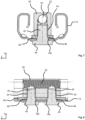
- Fig. 4 shows a longitudinal section of the rail pair of Fig. 3 .
- the spindle gear 70 supports a front end section 20a of the spindle 20.
- the spindle nut 30 is arranged centrally along the length of the spindle 20 in the state shown here.
- the spindle nut 30 screws itself along an external thread of the spindle 20 in or against the longitudinal direction x, depending on the direction of rotation, and thereby moves the first rail 12 relative to the second rail 14.
- a relative position between the spindle 10 and the spindle nut 30 also shifts accordingly.
- the spindle nut 30 has a continuous threaded bore with an internal thread 32 parallel to the longitudinal direction x.
- the internal thread 32 of the spindle nut 30 can be operatively connected to an external thread of the spindle 20.
- the spindle nut 30 is designed in one piece.
- FIGS. 5 to 8 show different views of a second rail 14 with a buffer 60, the spindle nut 30 and two fixing elements 40a, 40b.
- the spindle nut 30 is designed in one piece.
- the spindle nut 30 is attached to the second rail 14 by means of the two fixing elements 40a, 40b.
- the spindle nut 30 is centered by means of the two fixing elements 40a, 40b perpendicular to a longitudinal extension of the second rail 14 relative to a respective through opening 14a, 14b of the second rail 14, in particular a first through opening 14a and a second through opening 14b.
- the spindle nut 30 is centered horizontally by means of the two fixing elements 40a, 40b if the longitudinal extension of the second rail 14 runs parallel to the longitudinal direction x.
- the spindle nut 30 is centered by means of the two fixing elements 40a, 40b, in particular in the transverse direction y.
- the spindle nut 30 has a fixing opening 34 for each of the fixing elements 40a, 40b. Between the second rail 14 and the spindle nut 30 there is a buffer 60 The buffer 60 has a through hole for each of the two fixing elements 40a, 40b. Edge areas of the through holes of the buffer 60 are not necessarily in contact with the fixing elements 40a, 40b in the assembled state.
- the first fixing element 40a and the second fixing element 40b are screws in the present case.
- the first fixing element 40a and the second fixing element 40b are identical parts.
- the two fixing elements 40a, 40b each have a cone 46 in a transition area between a shaft 42 and a head section 44.
- the shaft 42 of each fixing element 40a, 40b has an external thread.
- the first through-opening 14a has, in particular before the spindle nut 30 and the first fixing element 40a are mounted, a substantially square cross-section with rounded corners.
- the first fixing element 40a is arranged in the first through-opening 14a.
- the dimension of the first through-opening 14a perpendicular to the longitudinal extension of the second rail 14, in particular in the transverse direction y is slightly smaller than the largest diameter of the cone 46 of the first fixing element 40a in an area adjacent to the head section 44 of the first fixing element 40a.
- the dimension of the first through-opening 14a parallel to the longitudinal extension of the second rail 14 is equal to the dimension of the first through-opening 14a perpendicular to the longitudinal extension of the second rail 14, in particular in the transverse direction y.
- the cone 46 of the first fixing element 40a causes a slight deformation of the edge regions of the first through-opening 14a contacted by the cone 46.
- the edge regions of the first through-opening 14a contacted by the cone 46 are deformed in the assembled state of the first fixing element 40a by displacement by the cone 46 in such a way that the cone 46 of the first fixing element 40a is evenly aligned with the edge regions of the first through-opening 14a and the head portion 44 of the first fixing element 40a securely comes into contact with the second rail 14.
- the second through-opening 14b has a substantially rectangular cross-section with rounded corners.
- the second fixing element 40b is arranged in the second through-opening 14b.
- the dimension of the second through-opening 14b perpendicular to the longitudinal extension of the second rail 14, in particular in the transverse direction y is slightly smaller than the largest diameter of the cone 46 of the second fixing element 40b in an area adjacent to the head section 44 of the second fixing element 40b.
- the dimension of the second through-opening 14b parallel to the longitudinal extension of the second rail 14 is larger than the largest diameter of the cone 46 of the second fixing element 40b.
- the cone 46 of the second fixing element 40b causes a slight deformation of the edge regions of the second through-opening 14b contacted by the cone 46, in particular the edge regions of the second through-opening 14b arranged laterally parallel to the longitudinal extension of the second rail 14.
- the edge regions of the second through-opening 14b contacted by the cone 46 are deformed in the assembled state of the second fixing element 40b by displacement by the cone 46 in such a way that the cone 46 of the second fixing element 40b is aligned centrally between the contacted opposite edge regions of the second through-opening 14b and the head section 44 of the second fixing element 40b comes into secure contact with the second rail 14.
Landscapes
- Engineering & Computer Science (AREA)
- Mechanical Engineering (AREA)
- Aviation & Aerospace Engineering (AREA)
- Transportation (AREA)
- General Engineering & Computer Science (AREA)
- Seats For Vehicles (AREA)
Claims (14)
- Système (10) de réglage longitudinal, présentant au moins une paire de rails, qui est formée par un premier rail (12) et par un deuxième rail (14), le premier rail (12) et le deuxième rail (14) étant aptes à être déplacés l'un par rapport à l'autre, en particulier dans une direction longitudinale (x), le premier rail (12) et le deuxième rail (14) s'entourant mutuellement en formant un canal intérieur (16), un écrou de broche (30) relié au deuxième rail (14) et une broche (20) en liaison fonctionnelle avec l'écrou de broche (30) étant agencés dans le canal intérieur (16), une transmission de broche (70), apte à être entraînée au moyen d'un moteur (80) et coopérant avec la broche (20), étant agencée sur le premier rail (12), l'écrou de broche (30) étant fixé sur le deuxième rail (14) au moyen d'un premier élément de fixation (40a) et d'un deuxième élément de fixation (40b),
caractérisé en ce que
l'écrou de broche (30) est centré au moyen des deux éléments de fixation (40a, 40b) perpendiculairement à une extension longitudinale du deuxième rail (14) dans une direction transversale (y), en ce que le premier élément de fixation (40a) est fixé par rapport à une première ouverture de passage (14a) et le deuxième élément de fixation (40b) est fixé par rapport à une deuxième ouverture de passage (14b), le premier élément de fixation (40a) étant centré par rapport à la première ouverture de passage (14a) et le deuxième élément de fixation (40b) étant centré par rapport à la deuxième ouverture de passage (14b) perpendiculairement à l'extension longitudinale du deuxième rail (14) dans la direction transversale (y). - Système (10) de réglage longitudinal selon la revendication 1, dans lequel le premier élément de fixation (40a), lors de son insertion dans la première ouverture de passage (14a), s'auto-centre au moyen d'un cône (46) aussi bien dans la direction longitudinale (x) du deuxième rail (14) que perpendiculairement à celle-ci dans la direction transversale (y).
- Système (10) de réglage longitudinal selon la revendication 1 ou la revendication 2, dans lequel les deux éléments de fixation (40a, 40b) comprennent chacun une tige (42) présentant un filetage extérieur et une section de tête (44), une zone de transition entre la tige (42) et la section de tête (44) comprenant un cône (46) respectif.
- Système (10) de réglage longitudinal selon l'une des revendications 1 à 3, dans lequel la première ouverture de passage (14a) présente une section transversale sensiblement carrée avec des coins arrondis.
- Système (10) de réglage longitudinal selon l'une des revendications 1 à 4, dans lequel la deuxième ouverture de passage (14b) présente une section transversale sensiblement rectangulaire avec des coins arrondis.
- Système (10) de réglage longitudinal selon l'une des revendications 1 à 5, les dimensions des deux ouvertures de passage (14a, 14b) étant identiques perpendiculairement à l'extension longitudinale du deuxième rail (14) dans la direction transversale (y).
- Système (10) de réglage longitudinal selon l'une des revendications 3 à 6, dans lequel le cône (46) de l'élément de fixation respectif (40a, 40b) présente un diamètre dans une zone adjacente à la section de tête respective (44), la dimension de l'ouverture de passage respective (14a, 14b) perpendiculaire à l'extension longitudinale du deuxième rail (14) dans la direction transversale (y) étant, avant le montage de l'élément de fixation (40a, 40b), légèrement inférieure au diamètre du cône (46).
- Système (10) de réglage longitudinal selon l'une des revendications 3 à 7, dans lequel la dimension de la deuxième ouverture de passage (14b) dans la direction de l'extension longitudinale du deuxième rail (14) est supérieure au diamètre du cône (46) du deuxième élément de fixation (40b).
- Système (10) de réglage longitudinal selon l'une des revendications 1 à 8, dans lequel le deuxième élément de fixation (40b) présente un jeu dans la deuxième ouverture de passage (14b) dans la direction de l'extension longitudinale du deuxième rail (14).
- Système (10) de réglage longitudinal selon l'une des revendications 1 à 9, dans lequel un tampon (60) est agencé entre le deuxième rail (14) et l'écrou de broche (30).
- Procédé de montage d'un système (10) de réglage longitudinal, le procédé présentant les étapes de procédé suivantes :a) préparation d'un deuxième rail (14), le deuxième rail (14) présentant une première ouverture de passage (14a) et une deuxième ouverture de passage (14b) pour la fixation d'un écrou de broche (30),b) mise en place de l'écrou de broche (30) sur le deuxième rail (14),c) insertion d'un premier élément de fixation (40a) dans l'écrou de broche (30) à partir d'un côté du deuxième rail (14) opposé à l'écrou de broche (30), à travers la première ouverture de passage (14a),d) insertion d'un deuxième élément de fixation (40b) dans l'écrou de broche (30) à partir d'un côté du deuxième rail (14) opposé à l'écrou de broche (30), à travers la deuxième ouverture de passage (14b),caractérisé en ce que
au moins l'un des deux éléments de fixation (40a, 40b) présente un cône (46) dans une zone de transition entre une tige (42) et une section de tête (44), ledit au moins un élément de fixation (40a, 40b) s'autocentrant lors de l'insertion de l'élément de fixation (40a, 40b) dans l'ouverture de passage (14a, 14b) associée au moyen du cône (46), et le cône (46) de l'élément de fixation (40a, 40b) déforme un bord de contact d'une zone de bordure de l'ouverture de passage (14a, 14b) associée. - Procédé selon la revendication 11, dans lequel la mise en place du premier élément de fixation (40a) et/ou du deuxième élément de fixation (40b) comprend un vissage dans l'écrou de broche (30).
- Siège de véhicule (1) comportant un système (10) de réglage longitudinal selon l'une des revendications 1 à 10.
- Siège de véhicule (1) selon la revendication 13, dans lequel le système (10) de réglage longitudinal est monté selon un procédé selon l'une des revendications 11 ou 12.
Applications Claiming Priority (3)
| Application Number | Priority Date | Filing Date | Title |
|---|---|---|---|
| DE102020127390 | 2020-10-16 | ||
| DE102021100601.5A DE102021100601B4 (de) | 2020-10-16 | 2021-01-14 | Längseinsteller, verfahren zur montage eines längseinstellers und fahrzeugsitz |
| PCT/IB2021/059515 WO2022079685A1 (fr) | 2020-10-16 | 2021-10-15 | Système de réglage en longueur, procédé de montage d'un système de réglage en longueur et siège de véhicule |
Publications (2)
| Publication Number | Publication Date |
|---|---|
| EP4204255A1 EP4204255A1 (fr) | 2023-07-05 |
| EP4204255B1 true EP4204255B1 (fr) | 2025-02-26 |
Family
ID=80929508
Family Applications (1)
| Application Number | Title | Priority Date | Filing Date |
|---|---|---|---|
| EP21801998.2A Active EP4204255B1 (fr) | 2020-10-16 | 2021-10-15 | Système de réglage en longueur, procédé de montage d'un système de réglage en longueur et siège de véhicule |
Country Status (6)
| Country | Link |
|---|---|
| US (1) | US12145475B2 (fr) |
| EP (1) | EP4204255B1 (fr) |
| JP (1) | JP7549141B2 (fr) |
| CN (1) | CN116368032A (fr) |
| DE (1) | DE102021100601B4 (fr) |
| WO (1) | WO2022079685A1 (fr) |
Families Citing this family (1)
| Publication number | Priority date | Publication date | Assignee | Title |
|---|---|---|---|---|
| DE102022210865A1 (de) * | 2022-10-14 | 2024-04-25 | Adient Us Llc | Längseinsteller, Fahrzeugsitz |
Family Cites Families (20)
| Publication number | Priority date | Publication date | Assignee | Title |
|---|---|---|---|---|
| GB8810854D0 (en) * | 1988-05-07 | 1988-06-08 | Barton Eng Ltd | Bush particularly for electrical enclosures |
| US5193868A (en) * | 1992-06-25 | 1993-03-16 | O'toole John T | Floating tapping plate assembly |
| JPH08188072A (ja) * | 1995-01-09 | 1996-07-23 | Jidosha Denki Kogyo Co Ltd | シートスライド装置 |
| DE19644419C1 (de) * | 1996-10-25 | 1997-11-27 | Schroff Gmbh | Baugruppenträger |
| JP2002144931A (ja) * | 2000-11-16 | 2002-05-22 | Johnson Controls Automotive Systems Corp | シートスライド装置 |
| FR2837148B1 (fr) | 2002-03-18 | 2004-07-02 | Faurecia Sieges Automobile | Mecanisme de reglage pour glissiere de siege de vehicule automobile ainsi que glissiere et siege equipes d'un tel mecanisme |
| FR2860457B1 (fr) * | 2003-10-02 | 2006-03-03 | Faurecia Sieges Automobile | Dispositif de reglage a vis sans fin, glissiere comportant un tel reglage et siege comportant une telle glissiere. |
| US20050214099A1 (en) * | 2004-03-29 | 2005-09-29 | Emc Corporation | Fastener for use in securing side rails to round-hole and square-hole mounting rails of cabinet racks |
| CA2505207A1 (fr) | 2004-05-13 | 2005-11-13 | Faurecia Automotive Seating Canada Limited | Appareil d'entrainement horizontal pour utilisation avec une glissiere de siege de vehicule |
| FR2882975B1 (fr) | 2005-03-14 | 2008-10-10 | Faurecia Sieges Automobile | Glissiere pour siege de vehicule et siege comportant une telle glissiere |
| JP4428282B2 (ja) | 2005-04-22 | 2010-03-10 | アイシン精機株式会社 | 車両用パワーシートスライド装置 |
| JP2008056003A (ja) | 2006-08-30 | 2008-03-13 | Fuji Kiko Co Ltd | 電動シートスライド装置 |
| DE102008024141A1 (de) * | 2008-05-19 | 2009-11-26 | Ims Gear Gmbh | Spindel-Lageranordnung für ein Sitzlängsverstellgetriebe |
| DE102013207665A1 (de) | 2013-01-30 | 2014-07-31 | C. Rob. Hammerstein Gmbh & Co. Kg | Spindelgetriebe für eine Verstellvorrichtung in einem Kraftfahrzeug sowie Fahrzeugsitz |
| DE102013224459A1 (de) | 2013-11-28 | 2015-05-28 | Schaeffler Technologies AG & Co. KG | Verbindungseinrichtung umfassend eine Abstandsbuchse und eine Schraube |
| SG11201803296UA (en) * | 2015-10-22 | 2018-05-30 | Penn Eng & Mfg Corp | Thin-sheet clinch fastener |
| US20180304777A1 (en) * | 2017-04-25 | 2018-10-25 | Toyota Boshoku Kabushiki Kaisha | Sliding device |
| DE102017218492B4 (de) | 2017-08-08 | 2022-12-22 | Keiper Seating Mechanisms Co., Ltd. | Längseinsteller und fahrzeugsitz |
| DE102019122928B3 (de) | 2019-06-14 | 2020-10-15 | Adient Engineering and IP GmbH | Längseinsteller und fahrzeugsitz |
| WO2021041908A1 (fr) * | 2019-08-30 | 2021-03-04 | Pollywog Toys, Llc | Meubles et structures de jeu à grande échelle présentant une modularité idéale |
-
2021
- 2021-01-14 DE DE102021100601.5A patent/DE102021100601B4/de active Active
- 2021-10-15 JP JP2023522768A patent/JP7549141B2/ja active Active
- 2021-10-15 WO PCT/IB2021/059515 patent/WO2022079685A1/fr not_active Ceased
- 2021-10-15 EP EP21801998.2A patent/EP4204255B1/fr active Active
- 2021-10-15 CN CN202180068500.7A patent/CN116368032A/zh active Pending
- 2021-10-15 US US18/247,667 patent/US12145475B2/en active Active
Also Published As
| Publication number | Publication date |
|---|---|
| JP2023545460A (ja) | 2023-10-30 |
| DE102021100601A1 (de) | 2022-04-21 |
| WO2022079685A1 (fr) | 2022-04-21 |
| JP7549141B2 (ja) | 2024-09-10 |
| EP4204255A1 (fr) | 2023-07-05 |
| DE102021100601B4 (de) | 2022-10-06 |
| US12145475B2 (en) | 2024-11-19 |
| CN116368032A (zh) | 2023-06-30 |
| US20240017642A1 (en) | 2024-01-18 |
Similar Documents
| Publication | Publication Date | Title |
|---|---|---|
| EP0694465B1 (fr) | Carrosserie de véhicule automobile comportant une traverse structurelle | |
| DE102017218492B4 (de) | Längseinsteller und fahrzeugsitz | |
| EP1590226B1 (fr) | Dispositif de serrage pour colonne de direction | |
| DE102015223485B4 (de) | Höheneinsteller für einen fahrzeugsitz, fahrzeugsitz | |
| EP1493634A1 (fr) | Module de coussin gonflable avec un boítiér recevant au moins un générateur de gaz et au moins un coussin gonflable | |
| DE69620623T2 (de) | Kardanischer antriebsblock zum einstellen eines fahrzeugsitzes | |
| EP2133233A2 (fr) | Agencement de palier de broche pour un mécanisme de réglage de longueur de siège | |
| EP4100279A1 (fr) | Dispositif de réglage longitudinal et siège de véhicule | |
| EP3983260B1 (fr) | Réglage longitudinal et siège de véhicule | |
| DE10254153B4 (de) | Klemmmechanismus für eine einstellbare Lenksäule | |
| DE102021100601B4 (de) | Längseinsteller, verfahren zur montage eines längseinstellers und fahrzeugsitz | |
| EP1382509B1 (fr) | Colonne de direction | |
| WO2022074028A1 (fr) | Dispositif de réglage longitudinal et siège de véhicule | |
| DE3111466A1 (de) | Verstellvorrichtung zum verstellen eines sitzes, insbesondere eines kraftfahrzeugsitzes | |
| DE102018216770B4 (de) | Baugruppe mit einer mit einer Bodenbaugruppe zu verbindenden Führungsschiene | |
| DE102020130226B4 (de) | Längseinsteller, Fahrzeugsitz | |
| EP4103428B1 (fr) | Dispositif de réglage avant-arrière de siège pour un siège, en particulier pour un siège de véhicule et siège de véhicule | |
| EP3825175B1 (fr) | Siège de véhicule | |
| EP3983261B1 (fr) | Réglage longitudinal, siège de véhicule | |
| EP1033278A2 (fr) | Procédé de fixation d'une glissière de siège | |
| EP0128111B1 (fr) | Mécanisme de déplacement longitudinal pour sièges de véhicules ayant un dispositif de déplacement actionné par moteur et un guidage longitudinal | |
| EP3366509B1 (fr) | Système de rail pour un dispositif de réglage en longueur et siège de véhicule | |
| DE102022208885A1 (de) | Längseinsteller für einen Fahrzeugsitz sowie Fahrzeugsitz | |
| DE10318153A1 (de) | Längseinsteller für einen Fahrzeugsitz | |
| DE4322353C2 (de) | Vorrichtung zum flächigen Befestigen eines Stoßfängerträgers an einer Kraftfahrzeugkarosserie |
Legal Events
| Date | Code | Title | Description |
|---|---|---|---|
| STAA | Information on the status of an ep patent application or granted ep patent |
Free format text: STATUS: UNKNOWN |
|
| STAA | Information on the status of an ep patent application or granted ep patent |
Free format text: STATUS: THE INTERNATIONAL PUBLICATION HAS BEEN MADE |
|
| PUAI | Public reference made under article 153(3) epc to a published international application that has entered the european phase |
Free format text: ORIGINAL CODE: 0009012 |
|
| STAA | Information on the status of an ep patent application or granted ep patent |
Free format text: STATUS: REQUEST FOR EXAMINATION WAS MADE |
|
| 17P | Request for examination filed |
Effective date: 20230331 |
|
| AK | Designated contracting states |
Kind code of ref document: A1 Designated state(s): AL AT BE BG CH CY CZ DE DK EE ES FI FR GB GR HR HU IE IS IT LI LT LU LV MC MK MT NL NO PL PT RO RS SE SI SK SM TR |
|
| DAV | Request for validation of the european patent (deleted) | ||
| DAX | Request for extension of the european patent (deleted) | ||
| GRAP | Despatch of communication of intention to grant a patent |
Free format text: ORIGINAL CODE: EPIDOSNIGR1 |
|
| STAA | Information on the status of an ep patent application or granted ep patent |
Free format text: STATUS: GRANT OF PATENT IS INTENDED |
|
| RIC1 | Information provided on ipc code assigned before grant |
Ipc: F16B 37/06 20060101ALN20240904BHEP Ipc: F16B 7/10 20060101ALN20240904BHEP Ipc: F16B 35/04 20060101ALI20240904BHEP Ipc: B60N 2/68 20060101ALI20240904BHEP Ipc: B60N 2/06 20060101AFI20240904BHEP |
|
| INTG | Intention to grant announced |
Effective date: 20240923 |
|
| GRAS | Grant fee paid |
Free format text: ORIGINAL CODE: EPIDOSNIGR3 |
|
| GRAA | (expected) grant |
Free format text: ORIGINAL CODE: 0009210 |
|
| STAA | Information on the status of an ep patent application or granted ep patent |
Free format text: STATUS: THE PATENT HAS BEEN GRANTED |
|
| AK | Designated contracting states |
Kind code of ref document: B1 Designated state(s): AL AT BE BG CH CY CZ DE DK EE ES FI FR GB GR HR HU IE IS IT LI LT LU LV MC MK MT NL NO PL PT RO RS SE SI SK SM TR |
|
| REG | Reference to a national code |
Ref country code: GB Ref legal event code: FG4D Free format text: NOT ENGLISH |
|
| REG | Reference to a national code |
Ref country code: CH Ref legal event code: EP |
|
| REG | Reference to a national code |
Ref country code: DE Ref legal event code: R096 Ref document number: 502021006808 Country of ref document: DE |
|
| REG | Reference to a national code |
Ref country code: IE Ref legal event code: FG4D Free format text: LANGUAGE OF EP DOCUMENT: GERMAN |
|
| REG | Reference to a national code |
Ref country code: DE Ref legal event code: R082 Ref document number: 502021006808 Country of ref document: DE Representative=s name: LIEDTKE & PARTNER PATENTANWAELTE, DE |
|
| REG | Reference to a national code |
Ref country code: NL Ref legal event code: MP Effective date: 20250226 |
|
| PG25 | Lapsed in a contracting state [announced via postgrant information from national office to epo] |
Ref country code: RS Free format text: LAPSE BECAUSE OF FAILURE TO SUBMIT A TRANSLATION OF THE DESCRIPTION OR TO PAY THE FEE WITHIN THE PRESCRIBED TIME-LIMIT Effective date: 20250526 |
|
| PG25 | Lapsed in a contracting state [announced via postgrant information from national office to epo] |
Ref country code: FI Free format text: LAPSE BECAUSE OF FAILURE TO SUBMIT A TRANSLATION OF THE DESCRIPTION OR TO PAY THE FEE WITHIN THE PRESCRIBED TIME-LIMIT Effective date: 20250226 |
|
| PG25 | Lapsed in a contracting state [announced via postgrant information from national office to epo] |
Ref country code: PL Free format text: LAPSE BECAUSE OF FAILURE TO SUBMIT A TRANSLATION OF THE DESCRIPTION OR TO PAY THE FEE WITHIN THE PRESCRIBED TIME-LIMIT Effective date: 20250226 |
|
| PG25 | Lapsed in a contracting state [announced via postgrant information from national office to epo] |
Ref country code: ES Free format text: LAPSE BECAUSE OF FAILURE TO SUBMIT A TRANSLATION OF THE DESCRIPTION OR TO PAY THE FEE WITHIN THE PRESCRIBED TIME-LIMIT Effective date: 20250226 |
|
| REG | Reference to a national code |
Ref country code: LT Ref legal event code: MG9D |
|
| PG25 | Lapsed in a contracting state [announced via postgrant information from national office to epo] |
Ref country code: IS Free format text: LAPSE BECAUSE OF FAILURE TO SUBMIT A TRANSLATION OF THE DESCRIPTION OR TO PAY THE FEE WITHIN THE PRESCRIBED TIME-LIMIT Effective date: 20250626 Ref country code: NO Free format text: LAPSE BECAUSE OF FAILURE TO SUBMIT A TRANSLATION OF THE DESCRIPTION OR TO PAY THE FEE WITHIN THE PRESCRIBED TIME-LIMIT Effective date: 20250526 |
|
| PG25 | Lapsed in a contracting state [announced via postgrant information from national office to epo] |
Ref country code: NL Free format text: LAPSE BECAUSE OF FAILURE TO SUBMIT A TRANSLATION OF THE DESCRIPTION OR TO PAY THE FEE WITHIN THE PRESCRIBED TIME-LIMIT Effective date: 20250226 |
|
| PG25 | Lapsed in a contracting state [announced via postgrant information from national office to epo] |
Ref country code: HR Free format text: LAPSE BECAUSE OF FAILURE TO SUBMIT A TRANSLATION OF THE DESCRIPTION OR TO PAY THE FEE WITHIN THE PRESCRIBED TIME-LIMIT Effective date: 20250226 |
|
| PG25 | Lapsed in a contracting state [announced via postgrant information from national office to epo] |
Ref country code: PT Free format text: LAPSE BECAUSE OF FAILURE TO SUBMIT A TRANSLATION OF THE DESCRIPTION OR TO PAY THE FEE WITHIN THE PRESCRIBED TIME-LIMIT Effective date: 20250626 Ref country code: LV Free format text: LAPSE BECAUSE OF FAILURE TO SUBMIT A TRANSLATION OF THE DESCRIPTION OR TO PAY THE FEE WITHIN THE PRESCRIBED TIME-LIMIT Effective date: 20250226 |
|
| PG25 | Lapsed in a contracting state [announced via postgrant information from national office to epo] |
Ref country code: GR Free format text: LAPSE BECAUSE OF FAILURE TO SUBMIT A TRANSLATION OF THE DESCRIPTION OR TO PAY THE FEE WITHIN THE PRESCRIBED TIME-LIMIT Effective date: 20250527 Ref country code: BG Free format text: LAPSE BECAUSE OF FAILURE TO SUBMIT A TRANSLATION OF THE DESCRIPTION OR TO PAY THE FEE WITHIN THE PRESCRIBED TIME-LIMIT Effective date: 20250226 |
|
| PG25 | Lapsed in a contracting state [announced via postgrant information from national office to epo] |
Ref country code: SE Free format text: LAPSE BECAUSE OF FAILURE TO SUBMIT A TRANSLATION OF THE DESCRIPTION OR TO PAY THE FEE WITHIN THE PRESCRIBED TIME-LIMIT Effective date: 20250226 |
|
| PG25 | Lapsed in a contracting state [announced via postgrant information from national office to epo] |
Ref country code: SM Free format text: LAPSE BECAUSE OF FAILURE TO SUBMIT A TRANSLATION OF THE DESCRIPTION OR TO PAY THE FEE WITHIN THE PRESCRIBED TIME-LIMIT Effective date: 20250226 |
|
| PG25 | Lapsed in a contracting state [announced via postgrant information from national office to epo] |
Ref country code: DK Free format text: LAPSE BECAUSE OF FAILURE TO SUBMIT A TRANSLATION OF THE DESCRIPTION OR TO PAY THE FEE WITHIN THE PRESCRIBED TIME-LIMIT Effective date: 20250226 |
|
| PG25 | Lapsed in a contracting state [announced via postgrant information from national office to epo] |
Ref country code: IT Free format text: LAPSE BECAUSE OF FAILURE TO SUBMIT A TRANSLATION OF THE DESCRIPTION OR TO PAY THE FEE WITHIN THE PRESCRIBED TIME-LIMIT Effective date: 20250226 |
|
| PG25 | Lapsed in a contracting state [announced via postgrant information from national office to epo] |
Ref country code: EE Free format text: LAPSE BECAUSE OF FAILURE TO SUBMIT A TRANSLATION OF THE DESCRIPTION OR TO PAY THE FEE WITHIN THE PRESCRIBED TIME-LIMIT Effective date: 20250226 Ref country code: CZ Free format text: LAPSE BECAUSE OF FAILURE TO SUBMIT A TRANSLATION OF THE DESCRIPTION OR TO PAY THE FEE WITHIN THE PRESCRIBED TIME-LIMIT Effective date: 20250226 |
|
| PG25 | Lapsed in a contracting state [announced via postgrant information from national office to epo] |
Ref country code: RO Free format text: LAPSE BECAUSE OF FAILURE TO SUBMIT A TRANSLATION OF THE DESCRIPTION OR TO PAY THE FEE WITHIN THE PRESCRIBED TIME-LIMIT Effective date: 20250226 |
|
| PG25 | Lapsed in a contracting state [announced via postgrant information from national office to epo] |
Ref country code: SK Free format text: LAPSE BECAUSE OF FAILURE TO SUBMIT A TRANSLATION OF THE DESCRIPTION OR TO PAY THE FEE WITHIN THE PRESCRIBED TIME-LIMIT Effective date: 20250226 |
|
| REG | Reference to a national code |
Ref country code: DE Ref legal event code: R097 Ref document number: 502021006808 Country of ref document: DE |
|
| PLBE | No opposition filed within time limit |
Free format text: ORIGINAL CODE: 0009261 |
|
| STAA | Information on the status of an ep patent application or granted ep patent |
Free format text: STATUS: NO OPPOSITION FILED WITHIN TIME LIMIT |
|
| PGFP | Annual fee paid to national office [announced via postgrant information from national office to epo] |
Ref country code: DE Payment date: 20251029 Year of fee payment: 5 |
|
| PGFP | Annual fee paid to national office [announced via postgrant information from national office to epo] |
Ref country code: AT Payment date: 20260113 Year of fee payment: 5 |
|
| PGFP | Annual fee paid to national office [announced via postgrant information from national office to epo] |
Ref country code: FR Payment date: 20251027 Year of fee payment: 5 |
|
| 26N | No opposition filed |
Effective date: 20251127 |