EP4053035B1 - Angebundenes verschlusssystem - Google Patents
Angebundenes verschlusssystem Download PDFInfo
- Publication number
- EP4053035B1 EP4053035B1 EP21382177.0A EP21382177A EP4053035B1 EP 4053035 B1 EP4053035 B1 EP 4053035B1 EP 21382177 A EP21382177 A EP 21382177A EP 4053035 B1 EP4053035 B1 EP 4053035B1
- Authority
- EP
- European Patent Office
- Prior art keywords
- closure
- neck portion
- tether
- lead
- container
- Prior art date
- Legal status (The legal status is an assumption and is not a legal conclusion. Google has not performed a legal analysis and makes no representation as to the accuracy of the status listed.)
- Active
Links
Images


Classifications
-
- B—PERFORMING OPERATIONS; TRANSPORTING
- B65—CONVEYING; PACKING; STORING; HANDLING THIN OR FILAMENTARY MATERIAL
- B65D—CONTAINERS FOR STORAGE OR TRANSPORT OF ARTICLES OR MATERIALS, e.g. BAGS, BARRELS, BOTTLES, BOXES, CANS, CARTONS, CRATES, DRUMS, JARS, TANKS, HOPPERS, FORWARDING CONTAINERS; ACCESSORIES, CLOSURES, OR FITTINGS THEREFOR; PACKAGING ELEMENTS; PACKAGES
- B65D55/00—Accessories for container closures not otherwise provided for
- B65D55/16—Devices preventing loss of removable closure members
-
- B—PERFORMING OPERATIONS; TRANSPORTING
- B65—CONVEYING; PACKING; STORING; HANDLING THIN OR FILAMENTARY MATERIAL
- B65D—CONTAINERS FOR STORAGE OR TRANSPORT OF ARTICLES OR MATERIALS, e.g. BAGS, BARRELS, BOTTLES, BOXES, CANS, CARTONS, CRATES, DRUMS, JARS, TANKS, HOPPERS, FORWARDING CONTAINERS; ACCESSORIES, CLOSURES, OR FITTINGS THEREFOR; PACKAGING ELEMENTS; PACKAGES
- B65D51/00—Closures not otherwise provided for
- B65D51/24—Closures not otherwise provided for combined or co-operating with auxiliary devices for non-closing purposes
- B65D51/242—Closures not otherwise provided for combined or co-operating with auxiliary devices for non-closing purposes provided with means for facilitating lifting or suspending of the container
-
- B—PERFORMING OPERATIONS; TRANSPORTING
- B65—CONVEYING; PACKING; STORING; HANDLING THIN OR FILAMENTARY MATERIAL
- B65D—CONTAINERS FOR STORAGE OR TRANSPORT OF ARTICLES OR MATERIALS, e.g. BAGS, BARRELS, BOTTLES, BOXES, CANS, CARTONS, CRATES, DRUMS, JARS, TANKS, HOPPERS, FORWARDING CONTAINERS; ACCESSORIES, CLOSURES, OR FITTINGS THEREFOR; PACKAGING ELEMENTS; PACKAGES
- B65D1/00—Rigid or semi-rigid containers having bodies formed in one piece, e.g. by casting metallic material, by moulding plastics, by blowing vitreous material, by throwing ceramic material, by moulding pulped fibrous material or by deep-drawing operations performed on sheet material
- B65D1/02—Bottles or similar containers with necks or like restricted apertures, designed for pouring contents
- B65D1/0223—Bottles or similar containers with necks or like restricted apertures, designed for pouring contents characterised by shape
- B65D1/023—Neck construction
- B65D1/0246—Closure retaining means, e.g. beads, screw-threads
-
- B—PERFORMING OPERATIONS; TRANSPORTING
- B65—CONVEYING; PACKING; STORING; HANDLING THIN OR FILAMENTARY MATERIAL
- B65D—CONTAINERS FOR STORAGE OR TRANSPORT OF ARTICLES OR MATERIALS, e.g. BAGS, BARRELS, BOTTLES, BOXES, CANS, CARTONS, CRATES, DRUMS, JARS, TANKS, HOPPERS, FORWARDING CONTAINERS; ACCESSORIES, CLOSURES, OR FITTINGS THEREFOR; PACKAGING ELEMENTS; PACKAGES
- B65D41/00—Caps, e.g. crown caps or crown seals, i.e. members having parts arranged for engagement with the external periphery of a neck or wall defining a pouring opening or discharge aperture; Protective cap-like covers for closure members, e.g. decorative covers of metal foil or paper
- B65D41/32—Caps or cap-like covers with lines of weakness, tearing-strips, tags, or like opening or removal devices, e.g. to facilitate formation of pouring openings
- B65D41/34—Threaded or like caps or cap-like covers provided with tamper elements formed in, or attached to, the closure skirt
- B65D41/3442—Threaded or like caps or cap-like covers provided with tamper elements formed in, or attached to, the closure skirt with rigid bead or projections formed on the tamper element and coacting with bead or projections on the container
- B65D41/3447—Threaded or like caps or cap-like covers provided with tamper elements formed in, or attached to, the closure skirt with rigid bead or projections formed on the tamper element and coacting with bead or projections on the container the tamper element being integrally connected to the closure by means of bridges
-
- B—PERFORMING OPERATIONS; TRANSPORTING
- B65—CONVEYING; PACKING; STORING; HANDLING THIN OR FILAMENTARY MATERIAL
- B65D—CONTAINERS FOR STORAGE OR TRANSPORT OF ARTICLES OR MATERIALS, e.g. BAGS, BARRELS, BOTTLES, BOXES, CANS, CARTONS, CRATES, DRUMS, JARS, TANKS, HOPPERS, FORWARDING CONTAINERS; ACCESSORIES, CLOSURES, OR FITTINGS THEREFOR; PACKAGING ELEMENTS; PACKAGES
- B65D2401/00—Tamper-indicating means
- B65D2401/15—Tearable part of the closure
- B65D2401/30—Tamper-ring remaining connected to closure after initial removal
Definitions
- the invention relates to a closing system combining a threaded closure and a matching container threaded neck portion, defining a container opening, to reversibly close the said container opening.
- the closure is of the type having a bottom tamper-evident band originally linked to a closure shell of the closure through frangible connections.
- frangible connections break forming an unattached tether preventing the closure shell and the tamper-evident band to form two separated individual components.
- the patent document US3904062 describes a closure system consisting of a screw closure provided with a tamper-evident band that remains axially retained in a container neck portion when the closure is unscrewed from the said container neck portion.
- the tamper-evident band is originally connected to the main body of the closure along frangible connections that are broken during a first opening operation of the container determining a tether that links the unscrewed main body of the closure to the tamper-evident band, which remains anchored to the container neck portion.
- the rupture of the frangible connections indicates to a user that the contents of the container may have been accessed.
- the tether prevents the unscrewed closure main body and the tamper-evident band, and therefore the container, to form two separated individual components. In other words, it prevents or inhibits the closure shell main body from being separated from the container. This favours the recycling of the container along with the complete closure parts.
- EP3584190 describes a closure system with some common features with that described in the previous reference. More specifically, the closure of EP3584190 comprises a closure shell having an annular skirt portion with first and second frangible connections that partially detachably connect the annular skirt portion with a tamper-evident band. When the frangible connections are broken a tether is exposed with one end attached to the annular skirt portion and with its opposite end attached to the tamper-evident band. In the system of EP3584190 the frangible connections are configured for the tether to extend greater than about 300 degrees around the circumference of the closure.
- EP3584190 by having the unattached portion of the tether extending greater than about 300 degrees, the distance of the closure shell from the container neck portion to which the tamper-evident band is anchored is increased, eliminating or reducing the chances of the closure shell from interfering with a user while drinking or pouring the content of the container.
- a long tether connecting in captive fashion the closure shell of the closure to the tamper-evident band would favor positioning the unscrewed closure shell of the closure moved away from the container opening region without the risk of the said closure shell accidentally reaching across the cross-section of the container opening, for example, when the container is tilted.
- the exposed tether is affected by a memory effect that makes it to naturally adopt a curved shape (due to the original circumferential arch shape that the strip of material, that later will determine the tether, has in the manufactured closure).
- the tether conventionally made of plastic, performs like a sort of a spring slightly biasing the closure shell towards the container opening.
- the patent document CN 208264903 U describes two embodiments of a tethered closure system wherein a tether can be pulled to adopt an exposed state when a cap is reclosed.
- a long tether may be manually folded outwards so as not to surround the bottle mouth to form a lifting ring of the bottle cap, so that a user can conveniently lift the plastic bottle.
- a short tether is pulled outwards, approaching their connecting portions with the cap and the safety ring, and the tether extends in a ring shape outside the bottle cap to form a lifting ring of the bottle cap. In both cases, if the tether is not manually pulled outwards it will surround the bottle mouth located between the cap body and the safety ring without protruding when the bottle is re-closed.
- the patent document CN1631740 which accords with the preamble of claim 1, relates to a safety bottle cap including the cap body and a safety ring linked under the body. It is of interest that there is a flexible permanent tether linking the cap body with the safety ring, this tether being over dimensioned to form a carrying handle, at least for the fingers to insert and pick up.
- This cap has advantages such as providing a safe seal, convenient environmental protection and in this case also easy carrying features.
- the proposed closure system combines a pair of a closure and a container neck portion with mating threaded formations offering multiple angular distributed engagement options with a tamper-evident band prevented from rotating around a lodging section of the said neck portion, whereby an optimal sizing of the tether will offer the user different closing options, at least one of which will force the tether to adopt an exposed state determining a protruding handle.
- the container neck portion defining a container opening with a central axis, is provided with an external thread formation including a reference finish lead and at least a first and a second auxiliar finish leads in a counterclockwise order, and an external shoulder beneath said external threaded formation.
- the closure comprises a closure shell with a top wall portion and an annular skirt portion provided with an internal thread formation mating with the external thread formation of the neck portion and including a reference closure lead and at least a first and a second auxiliar closure leads in a counterclockwise order.
- the closure shell further comprises an annular tamper-evident band dimensioned to remain engaged beneath the external shoulder and around a lodging section of the neck portion, and
- this closure system is characterized in that D1 is from 150 to 350; in that the length of the unattached tether is from 37 mm to 125 mm, and in that the tamper-evident band and the lodging section of the neck portion are configured to provide for a strong grip between them so as to impede the free rotation of the tamper-evident band during the first and subsequent opening operations of the container opening, such that when the closure shell is screwed on to the container neck portion during a re-closing operation of the container's opening by engaging the reference closure lead of the closure shell with the first auxiliary finish lead, instead of engaging it with the reference finish lead of the container neck portion, the tether adopts an exposed state B1 determining a protruding handle.
- the same tether that prevents the closure shell from being separated from the container offers for a protruding handle in case the user be in necessity thereof.
- the system always offers a coupling option to re-close the container wherein the tether will adopt its initial form adjacent and encircling the closure shell without protruding.
- a long tether can offer when combined with a pair of a closure shell and a container neck portion with mating threaded formations offering multiple angular distributed engagement options.
- the inventors have also revealed that by making use of the tether as a handle, the tether adopts a different shape when the closure shell is completely unscrewed from the container neck portion in a subsequent opening operation. Having the tether previously been subjected to pulling forces in a direction with a strong axial component when used as a handle, in the subsequent opening operation the tether adopts a shape that favors the arrangement of the closure shell outside the projection of the container opening, which is desirable and advantageous.
- D1 is selected enough to provide for at least two re-closing options wherein the tether adopts respective different exposed states, specifically enabling a re-closing operation of the container opening by engaging the reference closure lead of the closure shell with any of the first and the second auxiliary finish leads of the container neck portion, the tether transversally protruding more in the latter case.
- the invention envisages that the closure shell and the tamper-evidence band incorporate visual indications to provide the user with visual references
- D1 is approximately equal than R1.
- the invention envisages that in a set formed by the reference closure lead and the auxiliar closure leads, all the leads are regularly phased shifted with respect to the central axis.
- the internal thread formation has a number of three leads regularly phased shifted with respect to the central axis: the reference closure lead, a first auxiliar closure lead and second auxiliar closure lead.
- D1 is equal or greater than R1, being D1 also greater than 240.
- This closure system 100 comprises a polymeric closure 2 and a container neck portion 1 mutually engageable.
- the container neck portion 1 that defines a container opening 11 with a central axis 12, is provided with external threaded coupling means 13 and with an external shoulder 14 beneath said external threaded coupling means 13.
- the container can be made of a polymeric material and shaped as a bottle, such as a typical portable bottle storing a liquid product with a capacity of 1 liter.
- the closure 2 is of the type made of one-piece of polymeric material and is generally cylindrically shaped.
- the closure 2 has a closure shell 20, having a top wall portion 21 and an annular skirt portion 22 provided with internal threated coupling means 23 mating with the external threaded coupling means 13 of the neck portion 1; and a bottom annular tamper-evident band 24.
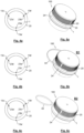
- Fig. 1a shows the closure system 100 in a manufactured closed state A of the container opening.
- the Fig. 1a is complemented with the detailed cross-sectional view of the Fig. 1b .
- the annular tamper-evident band 24 is dimensioned to be anchored beneath the shoulder 14 and around a lodging section 15 of the neck portion 1. This measure provides for a future axial retention of the tamper-evidence band 24 towards the container opening.
- the tamper-evident band 24 may have an internal profile with a continuous flange 24a or with discrete protrusions that, when the closure is first screwed on to close the container opening a snap engagement is established between the flange, or protrusions, of the annular tamper-evident band 24 and the shoulder 14 of the container neck portion 1.
- flange or protrusions may offer, for example, an introducing cam surface terminating in a flat engagement surface preferably perpendicular or essentially perpendicular to the central axis 12.
- the cam surface can be provided in an elastically deformable portion of the tamper-evident band 24. This is the case of the continuous flange 24 in the exemplary embodiment of the Fig. 2b .
- the annular skirt portion 22 of the closure shell 20 has, in a manufactured closed state A of the container opening, a connecting strip 3 encircling the closure shell 20 between the annular skirt portion 22 and the tamper-evident band 24, the strip 3 having an upper edge 31 attached to the annular skirt portion along an upper frangible connection 31a and a lower edge 32 attached to the tamper-evident band along a lower frangible connection 32a.
- frangible connections are intended to be broken when the closure shell 20 is unscrewed for the first time.
- the unscrew of the closure shell 20 during a first opening operation of the container opening starting from the manufactured closed state A displaces the annular skirt portion 22 upwards while the tamper-evident band 24 is axially retained in the container neck portion 1 and this results in rupture of the upper and the lower frangible connections 31a, 31b, the connecting strip 3 forming then the unattached tether 33.
- This tether 33 is showed in the Figs. 3a and 3b .
- the upper and the lower frangible connections 31a, 31b can be implemented by way of scoring lines, notches, leaders, lines of weaknesses, rows of pins, etc, formed (for example, moulded by sliders) or practiced (for example, laser scored) in the material conforming the closure shell 20, which can be selected, for example, from high density polyethylene (HDPE), polyethylene (PE), polypropylene (PP), Polyethylene terephthalate (PET) or blends thereof.
- HDPE high density polyethylene
- PE polyethylene
- PP polypropylene
- PET Polyethylene terephthalate
- the Fig. 3b particularly shows how the practical length L of the tether 33 is determined by the overlapping length of the upper and the lower frangible connections 31a, 32a.
- This length L will be conditional to the distance between the proximal end 31a' of the upper frangible connection 31a, adjacent to the permanent connection of the tether 33 with the annular skirt portion 22, and the proximal end 32a' of the lower frangible connection 32a, adjacent to the permanent connection of the tether 33 with the tamper-evidence band 24, as illustrated in the Fig. 3b .
- the invention envisages dimensioning D1 to be greater than 150.
- the closure system 100 deploys its potential when they include at least three leads each, in combination to a specific engagement of the tamper-evident band 24 in the lodging section 15 of the neck portion 1 and a proper selection of D1, preferably for a specific range of diameter dimensions of the closure 2, which in turn give rise to specific lengths L for the tether 33.
- the external thread formation 13 has a number of three finish leads having respective beginning points, in the proximity of the opening edge of the container opening neck 1, located roughly 120 degrees apart from each other: a reference finish lead 13a with a beginning point 13a', a first auxiliar finish lead 13b with a beginning point 13b' and a second auxiliar finish lead 13cwith a beginning point 13c', beginning points identified and properly labelled in the schemes of the Figs. 4a to 4c .
- the internal thread formation 23 of the annular skirt portion 22 of the closure shell 20 includes a reference closure lead 23a and at least a first and a second auxiliar closure leads 23b, 23c in the counterclockwise order.
- the internal thread formation 23 has a number of three closure leads having respective beginning points, in the proximity of the strip 3, also located roughly 120 degrees apart from each other: a reference closure lead 23a with a beginning point 23a', a first auxiliar closure lead 23b with a beginning point 23b' and a second auxiliar closure lead 23c with a beginning point 23c', beginning points identified and properly labelled as well in the schemes of the Figs. 4a to 4c .
- the tamper-evident band 24 and the lodging section 15 of the neck portion 1 are configured to provide for a strong grip between them so as to impede the free rotation of the tamper-evident band 24 during the first and subsequent opening operations of the container opening. That is, not only the shoulder 14 of the container neck portion 1 provides for an axial retention of the tamper-evident band 24 but also the said tamper-evident band 24 and the lodging section 15 of the container neck portion 1, which includes the above-mentioned shoulder 14, mechanically interfere each other to impede the free rotation of the tamper-evident band 24 relative to the container neck portion 1.
- This anti-rotation effect can be achieved simply by friction. It is also envisaged to provide the lodging section 15, including the shoulder 14, and/or the tamper-evident band 24 with anchoring means or anti-return means, stoppers, or the like, blocking the movement of the tamper-evident band 24 al least in the counterclockwise direction.
- Dimensioning the inner cross section of the annular tamper-evident band 24 to be less than that of the outer cross section of the lodging section 15 may be sufficient, taking advantage of the elastic properties offered by the candidate materials to manufacture the closure, which can be elastically deformed during a first coupling of the closure to the container neck portion, so that the tamper-evident band 24 be pressed tightly around the said lodging section 15 through restoring forces.
- This tightly adjustment is provided, in the exemplary embodiment of the invention, by the elastically deformable continuous flange 24a formed in the tamper-evident band 24.
- D1 is 270; the length L of the tether 33 is 94 mm (corresponding to a closure 2 of about 38 mm diameter); and the set of leads, either of the external thread formation 13 or of the internal thread formation 23, extend in a helical fashion and are configured to have to rotate the closure shell 20 R1 degrees about the central axis 12, to unscrew or screw it completely, wherein R1 is 200.
- Table 1 gives further examples to put into practice a closure system according to the invention. These examples are based on a closure obtained from polyolefins and following a conventional process of compression molding or injection molding with molded bridges or slitting operations.
- Table 1 Further exemplary embodiments of the closure system according to the invention D1 L (mm) R1 Number of leads per thread formation Appropriate for 150 37 180 ⁇ 25 3 Plastic bottles with a capacity from about 0,2L till 5 L (liters) 150 52 200 ⁇ 25 200 49 180 ⁇ 25 200 70 200 ⁇ 25 250 61 180 ⁇ 25 250 87 200 ⁇ 25 250 87 250 ⁇ 25 300 74 180 ⁇ 25 300 105 200 ⁇ 25 300 105 250 ⁇ 25 350 86 180 ⁇ 25 350 126 200 ⁇ 25
- the strip 3, subsequently determining the tether 33 preferably have a minimum cross section of 1,5 mm 2 , and more preferably of 2 mm 2 .
- the set of leads, for both the external thread formation 13 and the internal thread formation 23, extend in a helical fashion but, as indicated above, they can be configured to have to rotate the closure shell 20 different R1 degrees about the central axis 12 to be fully unscrewed or screwed on.
- D1 is always below 351.
- the upper and the lower frangible connections 31a and 32a cannot overlap along the entire circumference of the closure shell 20, specifically along the entire circumference of the annular skirt portion 22.
- the upper frangible connection 31a will extend around the circumference of the closure shell 20 except in the area that eventually forms the permanent attachment of the tether 33 to the closure shell 20; and the lower frangible connection 32a will extend around the circumference of the closure shell 20 except in the area that eventually forms the permanent attachment of the tether 33 to the tamper-evidence band 24.
- these permanent attachments extend at least along 5 degrees each about the central axis 12. Most preferably these permanent attachments extend at least along 10 degrees each about the central axis 12. It is not necessary that these permanent attachments to the closure shell 20 and to the tamper-evident band 24 extend each along the same degrees.
- the upper and the lower frangible connections 31a and 32a are parallel each other, determining a strip 3 and a subsequent unattached tether 33 of a constant width along its length L.
- D1 is approximately equal the R1 degrees the closure shell 20 has to be rotated about the central axis 12 to be fully unscrewed and screwed on, because this gives the user a visual indication to engage again the reference finish lead 13a with the reference closure lead 23a, opting for re-closing according to the i) option, previously described.
- This visual indication it is no other than the coincidence of the two opposing ends of the tether 33.
- D1 is greater than R1 and D1>240 degrees when the number of leads per thread formation is three, distributed 120 degrees from form each other.
- These visual indicators may be simple reliefs formed on the body of the closure shell 20 and the tamper-evidence band 24. This reliefs may include numbers, strips, dots, geometric shapes, arrows, etc. or a combination thereof.
Landscapes
- Engineering & Computer Science (AREA)
- Mechanical Engineering (AREA)
- Ceramic Engineering (AREA)
- Closures For Containers (AREA)
- Details Of Rigid Or Semi-Rigid Containers (AREA)
Claims (10)
- Verschlusssystem (100) umfassend einen Behälterhalsteil (1) und einen Verschluss (2) beide mit Gewindeausbildungen, welche mehrere winkelige verteilte gegenseitige Eingriffsmöglichkeiten anbieten, um den Behälterhalsteil (1) zu verschließen, wobei der Verschluss (2) eine Verschlusshülse (20) und eine manipulationssicheres Band (24) aufweist, welche durch zerbrechliche Verbindungen (31a, 32a) verbunden sind, welche brechen, wenn die Verschlusshülse (20) und der Behälterhalsteil (1) zum ersten Mal vollständig lose sind, unter Bildung eine ungebundene Anbindung (33), dadurch gekennzeichnet, dassmit dem manipulationssicheren Band (24) an einem Unterbringungsabschnitt (15) des Behälterhalsteils (1) verankert, das manipulationssichere Band (24) und der genannte Unterbringungsabschnitt (15) zusätzlich dazu ausgebildet sind, einen starken Griff zwischen denselben bereitzustellen, um die freie Rotation des manipulationssicheren Bandes (24) während des ersten und der nachfolgenden Lösevorgänge der Verschlusshülse (20) und des Behälterhalsteils (1) zu verhindern, und dassdie Länge der Anbindung (33) derart ist, dass das Verschlusssystem dem Benutzer unterschiedliche Wiederverschlussmöglichkeiten anbietet, eine, in welcher die Anbindung (33) eine Stellung einnimmt, sodass der benachbarte Behälterhalsteil (1) umgeben wird, ohne herauszuragen; und mindestens eine weitere Möglichkeit, in welcher die Anbindung (33) einen ausgesetzten Zustand einnimmt, unter Bestimmung eines herausragenden Haltegriffs.
- Verschlusssystem (100) nach Anspruch 1, dadurch gekennzeichnet, dass der Behälterhalsteil (1) eine Behälteröffnung (11), mit einer Mittelachse (12), definiert und mit Folgenden versehen ist- eine äußere Gewindeausbildung (13) beinhaltend eine Referenzschlussführung (13a) und mindestens eine erste und eine zweite Hilfsschlussführung (13b, 13c) entgegen der Uhrzeigerrichtung, und- eine äußere Schulter (14) unter der genannten äußeren Gewindeausbildung (13), der Verschluss (2), zum Verschließen der Behälteröffnung (11), Folgendes umfasst- eine Verschlusshülse (20) mit einem oberen Wandteil (21) und einem ringförmigen Schürzenteil (22) mit einer inneren Gewindeausbildung (23), welche mit der äußeren Gewindeausbildung (13) des Halsteils (1) zusammenpasst, und beinhaltend eine Referenzverschlussführung (23a) und mindestens eine erste und eine zweite Hilfsverschlussführung (23b, 23c) entgegen der Uhrzeigerrichtung,- das ringförmige manipulationssichere Band (24), welche derart dimensioniert ist, dass er unter der äußeren Schulter (14) und um den Unterbringungsabschnitt (15) des Behälterhalsteils (1) herum im Eingriff bleibt, und- einen Verbindungsstreifen (3), welcher die Verschlusshülse (20) zwischen dem ringförmigen Schürzenteil (22) und dem manipulationssicheren Band (24) umgibt, aufweisend einen oberen Rand (31), welcher am ringförmigen Schürzenteil (22) befestigt ist, und einen unteren Rand (32), welcher am manipulationssicheren Band (24) entlang einer jeweiligen oberen und einer jeweiligen unteren zerbrechlichen Verbindung (31a, 32a) befestigt ist, welche sich entlang mindestens D1-Grad um die Verschlusshülse (20) herum in einem gefertigten verschossenen Zustand (A) der Behälteröffnung (11) überlappen, in welchem die Referenzschlussführung (13a) und die Referenzverschlussführung (23a) miteinander im Eingriff sind,wodurch das vollständige Aufschrauben der Verschlusshülse (20) während des ersten Öffnungsvorgangs der Behälteröffnung (11), beginnend vom genannten gefertigten verschlossenen Zustand (A), das Brechen oder das Reißen der oberen und der unteren zerbrechlichen Verbindung (31a, 31b) ergibt, wobei der Verbindungsstreifen (3) dann die ungebundene Anbindung (33) bildet, welche die aufgeschraubte Verschlusshülse mit dem Behälterhalsteil (1) verknüpft, undwobeiD1 von 150 bis 350 ist,die Länge der Anbindung (33) von 37 mm bis 125 mm ist, sodass, wenn die Verschlusshülse (20) auf dem Behälterhalsteil (1) während eines Wiederverschlussvorgangs der Behälteröffnung (11) aufgeschraubt wird, indem die Referenzverschlussführung (23a) der Verschlusshülse (20) mit der ersten Hilfsschlussführung (13b) in Eingriff gebracht wird, statt sie mit der Referenzschlussführung (13a) des Behälterhalsteils (1) im Eingriff zu bringen, die Anbindung (33) einen ausgesetzten Zustand (B1) einnimmt, welcher einen herausragenden Haltegriff bestimmt.
- Verschlusssystem (100) nach Anspruch 2, dadurch gekennzeichnet, dass D1 genug ist, um mindestens zwei Wiederverschlussmöglichkeiten bereitzustellen, in welchen die Anbindung (33) jeweilige unterschiedliche ausgesetzte Zustände (B1, B2) einnimmt, spezifisch um einen Wiederverschlussvorgang der Behälteröffnung (11) zu ermöglichen, indem die Referenzverschlussführung (23a) der Verschlusshülse (20) mit einer der ersten und zweiten Hilfsschlussführungen (13b, 13c) des Behälterhalsteils (1) in Eingriff gebracht wird, wobei die Anbindung (33) im letzteren Fall quer mehr herausragt.
- Verschlusssystem nach einem der Ansprüche 2 oder 3, dadurch gekennzeichnet, dass die Verschlusshülse (20) und das manipulationssichere Band (24) visuelle Anweisungen integriert, um dem Benutzer visuelle Referenzen bereitzustellen,- um die Verschlusshülse (20) und den Behälterhalsteil (1) zum Aufschrauben der Verschlusshülse (20) während eines Wiederverschlussvorgangs der Behälteröffnung (11) gegenüberzustellen, indem die Referenzverschlussführung und die Schlussführung (23a, 13a) gegenseitig im Eingriff gebracht werden, und- um die Verschlusshülse (20) und den Behälterhalsteil (1) zum Aufschrauben der Verschlusshülse (20) während eines Wiederverschlussvorgangs der Behälteröffnung (11) gegenüberzustellen, indem die Referenzverschlussführung (23a) mit mindestens einer der ersten oder der zweiten Hilfsschlussführungen (13b, 13c) gegenseitig im Eingriff gebracht werden.
- Verschlusssystem nach einem der Ansprüche 2 bis 4, dadurch gekennzeichnet, dass, mit den zusammenpassenden äußeren und inneren Gewindeausbildungen (13, 23) so ausgebildet, dass die Verschlusshülse (20) R1-Grad rotiert werden muss, um die genannte Verschlusshülse (20) am Behälterhalsteil (1) vollständig aufzuschrauben, D1 etwa gleich R1 ist.
- Verschlusssystem nach einem der Ansprüche 2 bis 5, dadurch gekennzeichnet, dass in einem Satz gebildet aus der Referenzverschlussführung (23a) und den Hilfsverschlussführungen (23b, 23c), die genannten Führungen in Bezug auf die Mittelachse (12) regelmäßig phasenverschoben sind.
- Verschlusssystem nach einem der Ansprüche 2 bis 6, dadurch gekennzeichnet, dass die innere Gewindeausbildung (23) eine Anzahl von drei Führungen aufweist, welche in Bezug auf die Mittelachse (12) regelmäßig phasenverschoben sind: die Referenzverschlussführung (23a), eine erste Hilfsverschlussführung (23b) und eine zweite Hilfsverschlussführung (23c).
- Verschlusssystem nach dem vorhergehenden Anspruch, dadurch gekennzeichnet, dass D1 größer als 240 ist.
- Verschlusssystem nach einem der Ansprüche 2 bis 4, dadurch gekennzeichnet, dass- mit den zusammenpassenden äußeren und inneren Gewindeausbildungen (13, 23) so ausgebildet, dass die Verschlusshülse (20) R1-Grad rotiert werden muss, um die genannte Verschlusshülse (20) am Behälterhalsteil (1) vollständig aufzuschrauben, D1 größer als R1 ist; und dass- mit der inneren Gewindeausbildung (23) aufweisend eine Anzahl von drei Führungen, welche in Bezug auf die Mittelachse (12) regelmäßig phasenverschoben sind: die Referenzverschlussführung (23a), eine erste Hilfsverschlussführung (23b) und eine zweite Hilfsverschlussführung (23c), D1 größer als 240 ist.
- Verschlusssystem nach einem der Ansprüche 1 bis 9, dadurch gekennzeichnet, dass die Breite der ungebundenen Anbindung (33) an einem Mittelteil derselben erhöht ist.
Priority Applications (7)
| Application Number | Priority Date | Filing Date | Title |
|---|---|---|---|
| EP21382177.0A EP4053035B1 (de) | 2021-03-03 | 2021-03-03 | Angebundenes verschlusssystem |
| ES21382177T ES2987517T3 (es) | 2021-03-03 | 2021-03-03 | Un sistema de cierre con correa de unión |
| PCT/EP2022/054566 WO2022184528A1 (en) | 2021-03-03 | 2022-02-23 | A tethered closure system |
| US18/279,332 US11939125B2 (en) | 2021-03-03 | 2022-02-23 | Tethered closure system |
| BR112023016583A BR112023016583A2 (pt) | 2021-03-03 | 2022-02-23 | Sistema de fechamento provido de fita de amarração |
| PE2023002416A PE20241985A1 (es) | 2021-03-03 | 2022-02-23 | Un sistema de cierre con correa de union |
| CONC2023/0012004A CO2023012004A2 (es) | 2021-03-03 | 2023-09-11 | Un sistema de cierre con correa de unión |
Applications Claiming Priority (1)
| Application Number | Priority Date | Filing Date | Title |
|---|---|---|---|
| EP21382177.0A EP4053035B1 (de) | 2021-03-03 | 2021-03-03 | Angebundenes verschlusssystem |
Publications (3)
| Publication Number | Publication Date |
|---|---|
| EP4053035A1 EP4053035A1 (de) | 2022-09-07 |
| EP4053035B1 true EP4053035B1 (de) | 2024-05-22 |
| EP4053035C0 EP4053035C0 (de) | 2024-05-22 |
Family
ID=75223249
Family Applications (1)
| Application Number | Title | Priority Date | Filing Date |
|---|---|---|---|
| EP21382177.0A Active EP4053035B1 (de) | 2021-03-03 | 2021-03-03 | Angebundenes verschlusssystem |
Country Status (7)
| Country | Link |
|---|---|
| US (1) | US11939125B2 (de) |
| EP (1) | EP4053035B1 (de) |
| BR (1) | BR112023016583A2 (de) |
| CO (1) | CO2023012004A2 (de) |
| ES (1) | ES2987517T3 (de) |
| PE (1) | PE20241985A1 (de) |
| WO (1) | WO2022184528A1 (de) |
Families Citing this family (5)
| Publication number | Priority date | Publication date | Assignee | Title |
|---|---|---|---|---|
| EP4037991A4 (de) | 2019-09-30 | 2023-10-25 | Berry Global, Inc. | Zurückhaltbarer verschluss |
| AU2024251131A1 (en) | 2023-04-05 | 2025-09-25 | Husky Injection Molding Systems Ltd. | Closures with tamper evidence |
| USD1116829S1 (en) | 2023-06-13 | 2026-03-10 | Husky Injection Molding Systems Ltd. | Bottle cap |
| TR2024004647A2 (tr) * | 2024-04-18 | 2025-10-21 | Bericap Kapak Sanayi Anonim Sirketi | Bi̇r kapatma mekani̇zmasi |
| PL132375U1 (pl) * | 2024-09-25 | 2026-03-30 | Wałęsiak Robert | Nakrętka na butelkę paskiem łączącym |
Family Cites Families (11)
| Publication number | Priority date | Publication date | Assignee | Title |
|---|---|---|---|---|
| FR2329536A1 (fr) | 1973-07-02 | 1977-05-27 | Somepla Sa | Nouvelle capsule a vis inviolable et imperdable |
| SI20739A (sl) * | 2000-11-28 | 2002-06-30 | G.Loc, Trgovina In Storitve D.O.O. | Pokrov posode, prednostno steklenice oziroma plastenke |
| CN1631740A (zh) | 2005-01-01 | 2005-06-29 | 郭永军 | 铰接式防盗瓶盖 |
| CN1830730A (zh) | 2005-01-01 | 2006-09-13 | 郭永军 | 铰接式防盗瓶盖 |
| CN208264903U (zh) * | 2018-04-09 | 2018-12-21 | 宏全国际股份有限公司 | 具环带的环保瓶盖 |
| CN215324377U (zh) * | 2018-04-26 | 2021-12-28 | 奥布里斯特封闭瑞士有限公司 | 闭合件 |
| US20190375557A1 (en) | 2018-06-12 | 2019-12-12 | Closure Systems International Inc. | Tethered Closure |
| ES1218754Y (es) * | 2018-08-09 | 2019-01-10 | Betapack S A U | Tapon para botellas |
| CH715478A1 (de) * | 2018-10-29 | 2020-04-30 | Alpla Werke Alwin Lehner Gmbh & Co Kg | Verschlusskappe zum Verschliessen eines Behälters und Behälter mit einer solchen unverlierbar gehaltenen Verschlusskappe. |
| EP3880573B1 (de) | 2018-11-16 | 2023-06-07 | BERICAP Holding GmbH | Unverlierbarer verschluss |
| WO2020182854A1 (de) | 2019-03-11 | 2020-09-17 | Alpla Werke Alwin Lehner Gmbh & Co. Kg | Behälterverschluss und behälter |
-
2021
- 2021-03-03 EP EP21382177.0A patent/EP4053035B1/de active Active
- 2021-03-03 ES ES21382177T patent/ES2987517T3/es active Active
-
2022
- 2022-02-23 WO PCT/EP2022/054566 patent/WO2022184528A1/en not_active Ceased
- 2022-02-23 PE PE2023002416A patent/PE20241985A1/es unknown
- 2022-02-23 US US18/279,332 patent/US11939125B2/en active Active
- 2022-02-23 BR BR112023016583A patent/BR112023016583A2/pt unknown
-
2023
- 2023-09-11 CO CONC2023/0012004A patent/CO2023012004A2/es unknown
Also Published As
| Publication number | Publication date |
|---|---|
| ES2987517T3 (es) | 2024-11-15 |
| EP4053035A1 (de) | 2022-09-07 |
| WO2022184528A1 (en) | 2022-09-09 |
| US20240034527A1 (en) | 2024-02-01 |
| EP4053035C0 (de) | 2024-05-22 |
| PE20241985A1 (es) | 2024-09-26 |
| BR112023016583A2 (pt) | 2023-09-26 |
| CO2023012004A2 (es) | 2023-09-29 |
| US11939125B2 (en) | 2024-03-26 |
Similar Documents
| Publication | Publication Date | Title |
|---|---|---|
| EP4053035B1 (de) | Angebundenes verschlusssystem | |
| EP4140914B1 (de) | Dreh- und klappschlossverschluss | |
| EP3820783B1 (de) | Dreh- und schnappverschluss | |
| CA1199005B (en) | Resealable pour bottle with severing ring | |
| EP3305680B1 (de) | Stopfen für behälter | |
| AU661947B2 (en) | Single walled dispensing closures with positive alignment means | |
| US6821239B2 (en) | Snap-hinge closure with tamper-evident lid and method of making | |
| US10829274B2 (en) | Flip-top closure | |
| US8123056B2 (en) | Closure arrangement with opening indicating (anti-tamper) elements | |
| EP3670377B1 (de) | Am hals eines behälters befestigte verschlussvorrichtung | |
| JP4349698B2 (ja) | プラスチックキャップ | |
| JPH08183547A (ja) | 容器と合成樹脂製容器蓋との連結構造 | |
| EP2943418B1 (de) | Kappe mit originalitätsverschluss für behälter, behälter mit dieser kappe und vorformling zur herstellung des behälters | |
| JPS6111357A (ja) | ピルフア−プル−フ特性を有する容器蓋 | |
| JPS6218420B2 (de) | ||
| EP2045192A1 (de) | Klappverschluss | |
| EP4600172A1 (de) | Lightweight gelenkige kappe | |
| JP2025088336A (ja) | 虫侵入防止キャップ | |
| HK40130218A (en) | Lightweight articulated cap | |
| JPS62122956A (ja) | オレフイン系樹脂製容器蓋 | |
| JP2024173515A (ja) | 合成樹脂製螺子キャップ | |
| BR202022014916U2 (pt) | Disposição introduzida em tampa de garrafão com lacre | |
| JPH0442253B2 (de) | ||
| JPH04128251U (ja) | ピルフアープルーフキヤツプ付容器 | |
| JP2019142554A (ja) | 容器蓋 |
Legal Events
| Date | Code | Title | Description |
|---|---|---|---|
| PUAI | Public reference made under article 153(3) epc to a published international application that has entered the european phase |
Free format text: ORIGINAL CODE: 0009012 |
|
| STAA | Information on the status of an ep patent application or granted ep patent |
Free format text: STATUS: THE APPLICATION HAS BEEN PUBLISHED |
|
| AK | Designated contracting states |
Kind code of ref document: A1 Designated state(s): AL AT BE BG CH CY CZ DE DK EE ES FI FR GB GR HR HU IE IS IT LI LT LU LV MC MK MT NL NO PL PT RO RS SE SI SK SM TR |
|
| TPAC | Observations filed by third parties |
Free format text: ORIGINAL CODE: EPIDOSNTIPA |
|
| STAA | Information on the status of an ep patent application or granted ep patent |
Free format text: STATUS: REQUEST FOR EXAMINATION WAS MADE |
|
| 17P | Request for examination filed |
Effective date: 20230220 |
|
| RAX | Requested extension states of the european patent have changed |
Extension state: ME Payment date: 20230220 Extension state: BA Payment date: 20230220 |
|
| RBV | Designated contracting states (corrected) |
Designated state(s): AL AT BE BG CH CY CZ DE DK EE ES FI FR GB GR HR HU IE IS IT LI LT LU LV MC MK MT NL NO PL PT RO RS SE SI SK SM TR |
|
| GRAP | Despatch of communication of intention to grant a patent |
Free format text: ORIGINAL CODE: EPIDOSNIGR1 |
|
| STAA | Information on the status of an ep patent application or granted ep patent |
Free format text: STATUS: GRANT OF PATENT IS INTENDED |
|
| INTG | Intention to grant announced |
Effective date: 20240108 |
|
| GRAS | Grant fee paid |
Free format text: ORIGINAL CODE: EPIDOSNIGR3 |
|
| RAP3 | Party data changed (applicant data changed or rights of an application transferred) |
Owner name: CAP SUSTAINBLE SOLUTIONS S.L.U. |
|
| GRAA | (expected) grant |
Free format text: ORIGINAL CODE: 0009210 |
|
| STAA | Information on the status of an ep patent application or granted ep patent |
Free format text: STATUS: THE PATENT HAS BEEN GRANTED |
|
| AK | Designated contracting states |
Kind code of ref document: B1 Designated state(s): AL AT BE BG CH CY CZ DE DK EE ES FI FR GB GR HR HU IE IS IT LI LT LU LV MC MK MT NL NO PL PT RO RS SE SI SK SM TR |
|
| REG | Reference to a national code |
Ref country code: GB Ref legal event code: FG4D |
|
| REG | Reference to a national code |
Ref country code: CH Ref legal event code: EP |
|
| REG | Reference to a national code |
Ref country code: DE Ref legal event code: R096 Ref document number: 602021013547 Country of ref document: DE |
|
| REG | Reference to a national code |
Ref country code: IE Ref legal event code: FG4D |
|
| U01 | Request for unitary effect filed |
Effective date: 20240527 |
|
| U07 | Unitary effect registered |
Designated state(s): AT BE BG DE DK EE FI FR IT LT LU LV MT NL PT SE SI Effective date: 20240606 |
|
| PG25 | Lapsed in a contracting state [announced via postgrant information from national office to epo] |
Ref country code: IS Free format text: LAPSE BECAUSE OF FAILURE TO SUBMIT A TRANSLATION OF THE DESCRIPTION OR TO PAY THE FEE WITHIN THE PRESCRIBED TIME-LIMIT Effective date: 20240922 |
|
| PG25 | Lapsed in a contracting state [announced via postgrant information from national office to epo] |
Ref country code: HR Free format text: LAPSE BECAUSE OF FAILURE TO SUBMIT A TRANSLATION OF THE DESCRIPTION OR TO PAY THE FEE WITHIN THE PRESCRIBED TIME-LIMIT Effective date: 20240522 |
|
| PG25 | Lapsed in a contracting state [announced via postgrant information from national office to epo] |
Ref country code: GR Free format text: LAPSE BECAUSE OF FAILURE TO SUBMIT A TRANSLATION OF THE DESCRIPTION OR TO PAY THE FEE WITHIN THE PRESCRIBED TIME-LIMIT Effective date: 20240823 |
|
| PG25 | Lapsed in a contracting state [announced via postgrant information from national office to epo] |
Ref country code: PL Free format text: LAPSE BECAUSE OF FAILURE TO SUBMIT A TRANSLATION OF THE DESCRIPTION OR TO PAY THE FEE WITHIN THE PRESCRIBED TIME-LIMIT Effective date: 20240522 |
|
| PG25 | Lapsed in a contracting state [announced via postgrant information from national office to epo] |
Ref country code: PL Free format text: LAPSE BECAUSE OF FAILURE TO SUBMIT A TRANSLATION OF THE DESCRIPTION OR TO PAY THE FEE WITHIN THE PRESCRIBED TIME-LIMIT Effective date: 20240522 Ref country code: NO Free format text: LAPSE BECAUSE OF FAILURE TO SUBMIT A TRANSLATION OF THE DESCRIPTION OR TO PAY THE FEE WITHIN THE PRESCRIBED TIME-LIMIT Effective date: 20240822 Ref country code: IS Free format text: LAPSE BECAUSE OF FAILURE TO SUBMIT A TRANSLATION OF THE DESCRIPTION OR TO PAY THE FEE WITHIN THE PRESCRIBED TIME-LIMIT Effective date: 20240922 Ref country code: HR Free format text: LAPSE BECAUSE OF FAILURE TO SUBMIT A TRANSLATION OF THE DESCRIPTION OR TO PAY THE FEE WITHIN THE PRESCRIBED TIME-LIMIT Effective date: 20240522 Ref country code: GR Free format text: LAPSE BECAUSE OF FAILURE TO SUBMIT A TRANSLATION OF THE DESCRIPTION OR TO PAY THE FEE WITHIN THE PRESCRIBED TIME-LIMIT Effective date: 20240823 Ref country code: RS Free format text: LAPSE BECAUSE OF FAILURE TO SUBMIT A TRANSLATION OF THE DESCRIPTION OR TO PAY THE FEE WITHIN THE PRESCRIBED TIME-LIMIT Effective date: 20240822 |
|
| REG | Reference to a national code |
Ref country code: ES Ref legal event code: FG2A Ref document number: 2987517 Country of ref document: ES Kind code of ref document: T3 Effective date: 20241115 |
|
| PG25 | Lapsed in a contracting state [announced via postgrant information from national office to epo] |
Ref country code: CZ Free format text: LAPSE BECAUSE OF FAILURE TO SUBMIT A TRANSLATION OF THE DESCRIPTION OR TO PAY THE FEE WITHIN THE PRESCRIBED TIME-LIMIT Effective date: 20240522 |
|
| PG25 | Lapsed in a contracting state [announced via postgrant information from national office to epo] |
Ref country code: SK Free format text: LAPSE BECAUSE OF FAILURE TO SUBMIT A TRANSLATION OF THE DESCRIPTION OR TO PAY THE FEE WITHIN THE PRESCRIBED TIME-LIMIT Effective date: 20240522 Ref country code: RO Free format text: LAPSE BECAUSE OF FAILURE TO SUBMIT A TRANSLATION OF THE DESCRIPTION OR TO PAY THE FEE WITHIN THE PRESCRIBED TIME-LIMIT Effective date: 20240522 |
|
| PG25 | Lapsed in a contracting state [announced via postgrant information from national office to epo] |
Ref country code: SK Free format text: LAPSE BECAUSE OF FAILURE TO SUBMIT A TRANSLATION OF THE DESCRIPTION OR TO PAY THE FEE WITHIN THE PRESCRIBED TIME-LIMIT Effective date: 20240522 Ref country code: RO Free format text: LAPSE BECAUSE OF FAILURE TO SUBMIT A TRANSLATION OF THE DESCRIPTION OR TO PAY THE FEE WITHIN THE PRESCRIBED TIME-LIMIT Effective date: 20240522 Ref country code: CZ Free format text: LAPSE BECAUSE OF FAILURE TO SUBMIT A TRANSLATION OF THE DESCRIPTION OR TO PAY THE FEE WITHIN THE PRESCRIBED TIME-LIMIT Effective date: 20240522 |
|
| REG | Reference to a national code |
Ref country code: DE Ref legal event code: R097 Ref document number: 602021013547 Country of ref document: DE |
|
| PLBE | No opposition filed within time limit |
Free format text: ORIGINAL CODE: 0009261 |
|
| STAA | Information on the status of an ep patent application or granted ep patent |
Free format text: STATUS: NO OPPOSITION FILED WITHIN TIME LIMIT |
|
| 26N | No opposition filed |
Effective date: 20250225 |
|
| U20 | Renewal fee for the european patent with unitary effect paid |
Year of fee payment: 5 Effective date: 20250324 |
|
| PGFP | Annual fee paid to national office [announced via postgrant information from national office to epo] |
Ref country code: ES Payment date: 20250408 Year of fee payment: 5 |
|
| PG25 | Lapsed in a contracting state [announced via postgrant information from national office to epo] |
Ref country code: MC Free format text: LAPSE BECAUSE OF FAILURE TO SUBMIT A TRANSLATION OF THE DESCRIPTION OR TO PAY THE FEE WITHIN THE PRESCRIBED TIME-LIMIT Effective date: 20240522 |
|
| REG | Reference to a national code |
Ref country code: CH Ref legal event code: H13 Free format text: ST27 STATUS EVENT CODE: U-0-0-H10-H13 (AS PROVIDED BY THE NATIONAL OFFICE) Effective date: 20251024 |
|
| PG25 | Lapsed in a contracting state [announced via postgrant information from national office to epo] |
Ref country code: CH Free format text: LAPSE BECAUSE OF NON-PAYMENT OF DUE FEES Effective date: 20250331 |
|
| PG25 | Lapsed in a contracting state [announced via postgrant information from national office to epo] |
Ref country code: IE Free format text: LAPSE BECAUSE OF NON-PAYMENT OF DUE FEES Effective date: 20250303 |
|
| PGFP | Annual fee paid to national office [announced via postgrant information from national office to epo] |
Ref country code: GB Payment date: 20260303 Year of fee payment: 6 |