EP4053494B1 - Mesure de l'épaisseur à l'aide d'un système de courant de foucault pulsé - Google Patents
Mesure de l'épaisseur à l'aide d'un système de courant de foucault pulsé Download PDFInfo
- Publication number
- EP4053494B1 EP4053494B1 EP21160295.8A EP21160295A EP4053494B1 EP 4053494 B1 EP4053494 B1 EP 4053494B1 EP 21160295 A EP21160295 A EP 21160295A EP 4053494 B1 EP4053494 B1 EP 4053494B1
- Authority
- EP
- European Patent Office
- Prior art keywords
- time
- time point
- normalized
- flux
- thickness
- Prior art date
- Legal status (The legal status is an assumption and is not a legal conclusion. Google has not performed a legal analysis and makes no representation as to the accuracy of the status listed.)
- Active
Links
Images


Classifications
-
- G—PHYSICS
- G01—MEASURING; TESTING
- G01B—MEASURING LENGTH, THICKNESS OR SIMILAR LINEAR DIMENSIONS; MEASURING ANGLES; MEASURING AREAS; MEASURING IRREGULARITIES OF SURFACES OR CONTOURS
- G01B7/00—Measuring arrangements characterised by the use of electric or magnetic techniques
- G01B7/02—Measuring arrangements characterised by the use of electric or magnetic techniques for measuring length, width or thickness
- G01B7/06—Measuring arrangements characterised by the use of electric or magnetic techniques for measuring length, width or thickness for measuring thickness
- G01B7/10—Measuring arrangements characterised by the use of electric or magnetic techniques for measuring length, width or thickness for measuring thickness using magnetic means, e.g. by measuring change of reluctance
-
- G—PHYSICS
- G01—MEASURING; TESTING
- G01B—MEASURING LENGTH, THICKNESS OR SIMILAR LINEAR DIMENSIONS; MEASURING ANGLES; MEASURING AREAS; MEASURING IRREGULARITIES OF SURFACES OR CONTOURS
- G01B7/00—Measuring arrangements characterised by the use of electric or magnetic techniques
- G01B7/02—Measuring arrangements characterised by the use of electric or magnetic techniques for measuring length, width or thickness
- G01B7/06—Measuring arrangements characterised by the use of electric or magnetic techniques for measuring length, width or thickness for measuring thickness
- G01B7/10—Measuring arrangements characterised by the use of electric or magnetic techniques for measuring length, width or thickness for measuring thickness using magnetic means, e.g. by measuring change of reluctance
- G01B7/105—Measuring arrangements characterised by the use of electric or magnetic techniques for measuring length, width or thickness for measuring thickness using magnetic means, e.g. by measuring change of reluctance for measuring thickness of coating
-
- G—PHYSICS
- G01—MEASURING; TESTING
- G01D—MEASURING NOT SPECIALLY ADAPTED FOR A SPECIFIC VARIABLE; ARRANGEMENTS FOR MEASURING TWO OR MORE VARIABLES NOT COVERED IN A SINGLE OTHER SUBCLASS; TARIFF METERING APPARATUS; MEASURING OR TESTING NOT OTHERWISE PROVIDED FOR
- G01D5/00—Mechanical means for transferring the output of a sensing member; Means for converting the output of a sensing member to another variable where the form or nature of the sensing member does not constrain the means for converting; Transducers not specially adapted for a specific variable
- G01D5/12—Mechanical means for transferring the output of a sensing member; Means for converting the output of a sensing member to another variable where the form or nature of the sensing member does not constrain the means for converting; Transducers not specially adapted for a specific variable using electric or magnetic means
- G01D5/14—Mechanical means for transferring the output of a sensing member; Means for converting the output of a sensing member to another variable where the form or nature of the sensing member does not constrain the means for converting; Transducers not specially adapted for a specific variable using electric or magnetic means influencing the magnitude of a current or voltage
- G01D5/20—Mechanical means for transferring the output of a sensing member; Means for converting the output of a sensing member to another variable where the form or nature of the sensing member does not constrain the means for converting; Transducers not specially adapted for a specific variable using electric or magnetic means influencing the magnitude of a current or voltage by varying inductance, e.g. by a movable armature
-
- G—PHYSICS
- G01—MEASURING; TESTING
- G01N—INVESTIGATING OR ANALYSING MATERIALS BY DETERMINING THEIR CHEMICAL OR PHYSICAL PROPERTIES
- G01N27/00—Investigating or analysing materials by the use of electric, electrochemical, or magnetic means
- G01N27/72—Investigating or analysing materials by the use of electric, electrochemical, or magnetic means by investigating magnetic variables
-
- G—PHYSICS
- G01—MEASURING; TESTING
- G01B—MEASURING LENGTH, THICKNESS OR SIMILAR LINEAR DIMENSIONS; MEASURING ANGLES; MEASURING AREAS; MEASURING IRREGULARITIES OF SURFACES OR CONTOURS
- G01B2210/00—Aspects not specifically covered by any group under G01B, e.g. of wheel alignment, caliper-like sensors
- G01B2210/40—Caliper-like sensors
- G01B2210/46—Caliper-like sensors with one or more detectors on a single side of the object to be measured and with a transmitter on the other side
Definitions
- the present disclosure relates to non-contact measurement of a thickness of an object of an electrically conductive material by means of a Pulsed Eddy Current (PEC) system comprising a transmitter configured to generate a changing electromagnetic field which induces eddy currents in the object arranged within the electromagnetic field, and a receiver configured to detect a changing electromagnetic field generated by the eddy currents.
- PEC Pulsed Eddy Current
- PEC e.g. as described in US 5,059,902
- mechanical quantities such as electrical resistivity, thickness of non-ferrous metal sheets and edge position.
- the method works by creating a static magnetic field in the plate under measurement using a DC current in a transmitter coil.
- the magnetic field is then suddenly removed by turning off the current, depositing the magnetic energy in suitable load resistors.
- the first pulse resulting from the current cut-off is measured and its integral can be used to determine the distance between the plate and the coil.
- the current in the transmitter coil After the current in the transmitter coil has decayed, it is possible to start a measurement of the eddy currents induced in the plate by the sudden change of the applied magnetic field.
- the change of magnetic field due to the rapid decay of the eddy currents in the plate can induce a small signal which can be measured and analysed in order to deduce the resistivity and the thickness of the plate.
- the earliest part of the eddy current decay is independent of the thickness, and can be used to get a measure of the resistivity of the plate.
- the later part depends on the sheet resistance, so it depends on the resistivity divided by the thickness.
- the thickness of the plate can be deduced, e.g. as described in US 6,661,224 .
- US 7,701,205 discloses a PEC method of measurement of plate thickness where a transmitter coil is placed on one side of the plate and a receiver coil in placed on the other side of the plate.
- a potential drawback with the techniques described in the documents mentioned above is that coil systems on both sides of the object, e.g. a plate, are required. Since the distance between the coil systems and the object in a PEC based measurement system for fundamental reasons has to be quite small ( ⁇ 20mm), needing to physically fit the object in between the coil systems constrains the general applicability.
- One important example where above techniques are not usable is measurement of tube wall thickness, where it is normally not possible to have one of the coil systems within the tube.
- Another important example is measurement of thickness in the middle of a wide metal band (>1,5 m) during rolling, where it is practically impossible to keep the two coil systems at constant positions in relation to one another with a precision high enough to reach desired accuracy in the thickness measurement.
- the inability to use above described techniques for these measurement applications has so far affect the general applicability of PEC technology for thickness and resistivity measurement in metal industries.
- US 5,059,902 a general technique to determine resistivity and thickness of an object is described. This technique is possible to use to determine the thickness of an object, either for a general situation with different types of material and thicknesses with relatively lower accuracy, or with higher accuracy for a more limited range of materials and thicknesses.
- the reason for this is that to implement the method of US 5,059,902 which gives three measured values for every set of position, resistivity and thickness where all relations between measured values and physical parameters are nonlinear and unknown is unwieldy.
- test measurements with different test plates must be done to establish the relations and to describe them and later use them to determine physical parameters.
- the resistivity can vary a factor 10, for instance from 20 n ⁇ m to 200 n ⁇ m.
- the desired accuracy of measurement of the physical parameters is 0,1%, which is a normal accuracy level in metal industry today, test measurements to establish the relation must be done for at least every 2% change of physical parameter value, this since the relation between the physical parameter and measurement is strongly nonlinear and unknown. The consequence of this is that around 14 000 tests with different values of the parameters resistivity and thickness has to be performed for this example, meaning that the same number of test objects, plates, must be produced and tested to supply enough information. For practical and economic reasons it may be impossible to handle that large amount test objects. To create a working measurement method based on US 5,059,902 it is necessary to either accept a lower accuracy, or using the method within a more constrained parameter region.
- a method of non-contact measurement of a thickness of an object of an electrically conductive material by means of a PEC system comprising a transmitter coil and a receiver coil.
- the method comprises, during a predetermined supply time period, supplying a constant current to the transmitter coil, said supplied current generating an electromagnetic field which penetrates the object.
- the method also comprises, after the supply time period, after a start time point t o , turning off the supplied current, resulting in induced eddy currents in the object and a decaying magnetic field.
- the method also comprises, at the receiver coil, during a predetermined measurement time period starting at said start time point t 0 , measuring a voltage induced by the decaying magnetic field.
- the voltage is converted to a magnetic flux by integration, and is measured at a first time point t 1 , a second time point t 2 and at least one later time point t 3 .
- the method also comprises calculating a total magnetic flux ⁇ 1 which is generated by the eddy currents at the first time point t 1 and picked up by the receiver coil, by comparing the measured flux ⁇ plate at the first time point t 1 with a predetermined total flux ⁇ 0 picked up by the receiver coil when no object is present, wherein the first time point t 1 is set to the earliest time satisfying the provision that the magnetic flux ⁇ (t 1 ) at the first time point t 1 is zero when no object is present.
- the method also comprises normalizing measured magnetic flux ⁇ ec resulting from the eddy currents and picked up by the receiver coil, using the calculated total magnetic flux ⁇ 1 as a normalization factor such that the normalized eddy current flux ⁇ ec is independent of a distance between the between the object and the transmitter and receiver coils whereby the normalized eddy current flux ⁇ ec is zero at the first time point t 1 and 1 at a time after the eddy currents have died out.
- a computer program product comprising computer-executable components for causing a controller of an embodiment of a PEC system to perform the method of the present disclosure when the computer-executable components are run on processing circuitry comprised in the controller.
- a PEC system for non-contact measurement of a thickness of an object of an electrically conductive material.
- the PEC system comprises a transmitter coil, a receiver coil and a controller.
- the controller comprises processing circuitry and storage storing instructions executable by said processing circuitry whereby said controller is operative perform an embodiment of the method of the present disclosure.
- the thickness and resistivity of the object can be unambiguously determined by PEC measurements at different time points.
- Figure 1 illustrates an embodiment of a PEC system 10 arranged for measuring the thickness d of an object 1, typically a plate (which may also be called sheet metal or metal strip) of an electrically conductive material, typically a non-ferrous electrically conductive material such as Al, the object having a first (here lower) side 4a and a second (here upper) side 4b.
- the object 1 in the form of a plate has a longitudinal axis which is perpendicular to the plane of the figure.
- the object 1 is exemplified as a plate, but the object may have other shapes in some embodiments.
- the PEC system 10 comprises a transmitter coil 2 of a transmitter and a receiver coil 3 of a receiver.
- both of the transmitter coil 2 and the receiver coil 3 are arranged on the same side of the object 1, which is preferred in some embodiments.
- the receiver coil 3 may be arranged on the opposite side of the object 1 in relation to the transmitter coil 2.
- the transmitter coil 2 is configured to generate a sudden change of the supplied electromagnetic field which induces eddy currents in the object 1 arranged within the electromagnetic field
- the receiver coil 3 is configured for allowing an electrical voltage to be induced therein by the changing electromagnetic field generated e.g. first by the collapsing magnetic field when the current through the transmitter coil is turned off and then by the eddy currents.
- the PEC system 10 may comprise a controller 6 for controlling the transmitter and the receiver via control signalling e.g. as illustrated by the dashed lines in the figure.
- the controller 6 may also be configured with circuitry for analysing the voltage induced in the receiver coil 3 by eddy currents in the object 1 in order to determine the thickness d of the object, as further described below.
- the controller may be formed as a separate device, or be partly or fully integrated with the transmitter and/or receiver.
- the controller 6 may e.g. comprise a central controller device which is arranged separate from the transmitter and receiver and distributed controller device(s) integrated with the transmitter and/or receiver.
- the magnitude of the eddy currents generated in the plate 1 when the transmitter current I Tr is turned off depends on the dimensions of the transmitter coil 2, the magnitude of the transmitter current I Tr and the distance D between the coil 2 and the plate 1.
- the total flux ⁇ 0 generated by the transmitter current I Tr which is picked up by the receiver coil 3 is measured, as explained in the following.
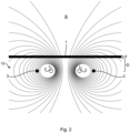
- Figure 2 shows a cross section of the magnetic field B (B denotes the magnetic flux/field density which is commonly also called magnetic field) generated by the transmitter current I Tr flowing through the transmitter coil 2.
- the cross section of the transmitter coil is illustrated as the two inner (non-filled) dots, symbolizing where a turn of the coil passes perpendicular through the plane of the figure.
- the cross section of the receiver coil 3 is seen as the two outer (filled/black) dots.
- the transmitter coil 2 is thus positioned within the receiver coil 3, e.g. concentrically, but in other embodiments of the present invention, the transmitter and receiver coils may be otherwise positioned in relation to each other, e.g. side by side along an axis parallel to the plate 1.
- both the transmitter coil and the receiver coil are positioned on the same side of the plate when in use.
- the field lines are in accordance with a circular transmitter coil 2 with a single turn, but either of the transmitter and receiver coils may have any suitable shape and/or any number of turns, depending on the application.
- the distribution of the magnetic field is shown as it is a sufficiently long time after the application of the constant (DC) transmitter current, when the possible influence of the eddy currents has died out. Then, the distribution of the field B is independent of the presence of the plate 1.
- the total flux ⁇ picked up by each turn of the receiver coil 3 is by definition equal to the surface integral of the magnetic field density B over the surface S encircled by the turn of the receiver coil 3:
- the first time point t 1 is set to when the magnetic flux ⁇ (t 1 ) is zero if no plate 1 is present.
- the current in the transmitter coil is turned off, the current through the transmitter coil will decrease exponentially and not reach zero in a mathematical sense. That the magnetic flux ⁇ (t 1 ) is zero here thus implies that the flux is negligible, below a detection threshold or substantially zero.
- the required time t 1 depends on the inductances of the PEC system 10, the capacitances and the value of any damping resistors.
- the time t 1 is thus a constant which depends on the design parameters of the system 10.
- the magnetic field B in figure 3 above the plate 1 is the same as in figure 2 .
- This field is mirrored to below the plate 1 by the symmetry of eddy currents in the plate.
- the field B in figure 3 is generated by the eddy currents alone, and is proportional to the magnitude of these.
- the total flux ⁇ (t 1 ) when a plate 1 is present, generated by the eddy currents at time t 1 , which is picked up by the receiver coil 3 is designated as ⁇ 1 .
- ⁇ 1 ⁇ 0 ⁇ ⁇ Plate
- the integration is started at time t 1 and integrated for an additional time t:
- the eddy currents are concentrated to the surface of the plate 1 which is closest to the transmitter coil 2 (the bottom surface 4a, see figure 1 , in figures 2 and 3 ). They are then dissipated and spread out due to the influence of the electrical resistivity ⁇ of the plate.
- the time dependence depends on the resistivity only.
- the time dependence is more complicated and depends on both the resistivity and the thickness.
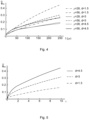
- figure 4 describes the time dependence of the normalized eddy current flux ⁇ ec for six plates 1 of three different thicknesses d, 1.5, 3 and 4.5 mm, respectively, each of two different resistivities ⁇ , 28 and 56 n ⁇ m, respectively.
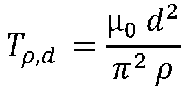
- the dissipation of the eddy currents generated by cutting off the transmitter current I Tr is described by a three-dimensional diffusion equation and time can be normalized to the characteristic time scale of the problem, namely T ⁇ , d ⁇ ⁇ ⁇ d 2 ⁇ 2 ⁇
- T is the time constant corresponding to the rate of diffusion
- d is the thickness of the plate
- ⁇ is the resistivity of the plate
- ⁇ 0 is the magnetic permeability of vacuum.
- the time constant T may be estimated/calculated based on a nominal thickness of the object 1, e.g.
- a first assumed value for ⁇ gives an estimated value for T which results in the determination of a new ⁇ which in its turn can be used for estimating a new T and so on until T can be calculated with desired precision.
- the characteristic time scale describes the time it takes for the eddy currents to diffuse and reach the surface facing away from the transmitter coil 2 (i.e. the top surface 4b, see figure 1 , in figures 2 and 3 ). This is also the time after which the time dependence of the normalized eddy current flux ⁇ ec is influenced by the thickness d of the plate 1.
- a value of ⁇ of e.g. 2 implies that the real time t (typically in microseconds) corresponds to two time constants T of the measured plate 1.
- a first measurement is performed at an early time ⁇ 2 , when the normalized eddy current flux ⁇ ec ( ⁇ 2 ) is only dependent on the resistivity of the plate.
- the normalized time ⁇ 2 should be less than, or on the order of unity (i.e. 1).
- a second measurement is then performed at a later normalized time ⁇ 3 , when the normalized eddy current flux ⁇ ec ( ⁇ 3 ) is only dependent on the thickness of the plate.
- the value of this normalized time ⁇ 3 can be selected on the basis of other criteria which determine the performance of the system 10, such as the signal-to-noise ratio at the receiver coil 3.
- a value of at least 2 and/or of less than 10 is appropriate for ⁇ 3 .
- the measuring of a voltage induced by the decaying magnetic field at a (here, at least one) third time point t 3 includes at least two measurement(s) at respective later (third) time points, e.g.
- the thickness measurement of the object 1 may be repeated as often as possible in order to give dense samples of an object with a thickness which changes with the time. This would e.g. be the case when measuring the thickness of material produced in a rolling mill.
- the interval between thickness measurements should be sufficiently long to prevent any influence of eddy currents induced in the object in connection with the preceding thickness measurement(s) from disturbing the later thickness measurement(s).
- the timescale for this process may be determined by the so-called sheet resistivity of the object 1, typically a plate.
- the sheet resistivity is defined as the resistivity of the object divided by its thickness.
- An appropriate supply time in microseconds can then be computed as the plate thickness, typically the nominal thickness of the object 1, in ⁇ m divided by the resistivity in n ⁇ m and multiplied by seventeen.
- a knowledge of the resistivity ⁇ and thickness d of the plate to be measured may be convenient. Normally, the nominal thickness of the plate is known and the resistivity may be obtained from the measurement, whereby the correct time scale may be obtained in an iterative manner. The thickness measurement is still possible if the thickness is not known beforehand, through iteration.
- FIG. 6 is a flow chart illustrating some embodiments of the method of the invention.
- the method is for non-contact measurement of the thickness d of an object 1 of an electrically conductive material by means of a PEC system 10 comprising a transmitter coil 2 and a receiver coil 3.
- the method comprises, during a predetermined supply time period, supplying S1 a constant current to the transmitter coil 2, said supplied current generating an electromagnetic field B which penetrates the object 1.
- the method also comprises, after the supply time period, after a start time point t 0 , turning off S 2 the supplied current, resulting in induced eddy currents in the object and a decaying magnetic field B.
- the method also comprises, at the receiver coil 3, during a predetermined measurement time period starting at said start time point t 0 , measuring S 3 a voltage induced by the decaying magnetic field at a first time point t 1 , a second time point t 2 and at least one later or third time point t 3 .
- the method also comprises calculating S 4 a total magnetic flux ⁇ 1 which is generated by the eddy currents at the first time point t 1 and picked up by the receiver coil 3, by comparing the measured flux ⁇ plate at the first time point t 1 with a predetermined total flux ⁇ 0 picked up by the receiver coil when no object 1 was present, wherein the first time point t 1 is set to the earliest time satisfying the provision that the magnetic flux ⁇ (t 1 ) at the first time point t 1 is zero when no object is present.
- the method also comprises normalizing S 5 measured magnetic flux ⁇ ec resulting from the eddy currents and picked up by the receiver coil 3, using the calculated S 4 total magnetic flux ⁇ 1 as a normalization factor such that the normalized eddy current flux ⁇ ec is independent of a distance D between the object 1 and the transmitter and receiver coils whereby the normalized eddy current flux ⁇ ec is zero at the first time point t 1 and 1 at a time after the eddy currents have died out.
- FIG. 7 schematically illustrates an embodiment of the controller 6 of the present disclosure.
- the controller 6 comprises processing circuitry 61 e.g. a central processing unit (CPU).
- the processing circuitry 61 may comprise one or a plurality of processing units in the form of microprocessor(s). However, other suitable devices with computing capabilities could be comprised in the processing circuitry 61, e.g. an application specific integrated circuit (ASIC), a field programmable gate array (FPGA) or a complex programmable logic device (CPLD).
- ASIC application specific integrated circuit
- FPGA field programmable gate array
- CPLD complex programmable logic device
- the processing circuitry 61 is configured to run one or several computer program(s) or software (SW) 63 stored in a storage 62 of one or several storage unit(s) e.g. a memory.
- SW software
- the storage unit is regarded as a computer readable means, forming a computer program product 62 together with the SW 63 stored thereon as computer-executable components, as discussed herein and may e.g. be in the form of a Random Access Memory (RAM), a Flash memory or other solid state memory, or a hard disk, or be a combination thereof.
- the processing circuitry 61 may also be configured to store data in the storage 62, as needed.
- the controller 6 may be configured to perform the method of the present disclosure.
Landscapes
- Physics & Mathematics (AREA)
- General Physics & Mathematics (AREA)
- Chemical & Material Sciences (AREA)
- Chemical Kinetics & Catalysis (AREA)
- Electrochemistry (AREA)
- Health & Medical Sciences (AREA)
- Life Sciences & Earth Sciences (AREA)
- Analytical Chemistry (AREA)
- Biochemistry (AREA)
- General Health & Medical Sciences (AREA)
- Immunology (AREA)
- Pathology (AREA)
- Measurement Of Length, Angles, Or The Like Using Electric Or Magnetic Means (AREA)
- Investigating Or Analyzing Materials By The Use Of Magnetic Means (AREA)
Claims (7)
- Procédé de mesure sans contact d'une épaisseur (d) d'un objet (1) constitué d'un matériau électriquement conducteur au moyen d'un système à courants de Foucault pulsés, PEC, (10) comprenant une bobine émettrice (2) et une bobine réceptrice (3), le procédé comprenant :durant un intervalle de temps d'alimentation prédéterminé, la fourniture (S1) d'un courant constant à la bobine émettrice (2), ledit courant fourni générant un champ électromagnétique (B) qui pénètre dans l'objet (1) ;après l'intervalle de temps d'alimentation, après un instant de début t0, la coupure (S2) du courant fourni pour engendrer des courants de Foucault induits dans l'objet et un champ magnétique décroissant (B) ;au niveau de la bobine réceptrice (3), durant un intervalle de temps de mesure prédéterminé débutant audit instant de début t0, la mesure (S3) d'une tension induite par le champ magnétique décroissant à un premier instant t1, un deuxième instant t2 et au moins un instant ultérieur t3;le calcul (S4) d'un flux magnétique total Φ1 qui est généré par les courants de Foucault au premier instant t1 et capté par la bobine réceptrice (3), par comparaison du flux mesuré Φplate au premier instant t1 à un flux total prédéterminé Φ0 capté par la bobine réceptrice en l'absence d'objet (1), le premier instant t1 étant fixé à l'instant le plus tôt remplissant la condition que le flux magnétique Φ(t1) au premier instant t1 soit nul en l'absence d'objet, Φ1 étant calculé (S4) sous la forme Φ0-Φplate ;la normalisation (S5) d'un flux magnétique mesuré Φec engendré par les courants de Foucault et capté par la bobine réceptrice (3), en utilisant comme facteur de normalisation le flux magnétique total Φ1 calculé (S4) de sorte que le flux dû aux courants de Foucault normalisé Φ̂ ec soit indépendant d'une distance (D) entre l'objet (1) et les bobines émettrice et réceptrice (2, 3), moyennant quoi le flux dû aux courants de Foucault normalisé Φ̂ ec est nul au premier instant t1 et vaut 1 à un instant suivant la dissipation des courants de Foucault ;l'association (S6) du flux dû aux courants de Foucault normalisé Φ̂ ec à un temps normalisé τ en utilisant comme facteur de normalisation une constante de temps T, de sorte que τ=0 lorsque le temps réel t=t1 et τ=1 lorsque, après la coupure du courant fourni, les courants de Foucault se sont diffusés pour tout juste atteindre une surface de l'objet (1) tournée à l'opposé de la bobine émettrice (2), moyennant quoi le flux dû aux courants de Foucault normalisé Φ̂ ec est indépendant de l'épaisseur (d) au sein de l'intervalle de temps normalisé allant de τ=0 à τ=1 et indépendant de la résistivité (ρ) de l'objet (1) à des temps au-delà de τ=1, la constante de temps T étant calculée sous la forme :
 d étant l'épaisseur de l'objet, telle qu'estimée précédemment, ρ étant la résistivité de l'objet, telle qu'estimée précédemment, et u0 étant la perméabilité magnétique du vide ; etsur la base des mesures au premier instant, au deuxième instant et à l'instant ultérieur, la détermination (S7) de l'épaisseur (d) et de la résistivité (ρ) de l'objet (1), le deuxième instant t2 étant fixé au sein de l'intervalle de temps normalisé allant de τ=0 à τ=2, le flux dû aux courants de Foucault normalisé Φ̂ ec (τ2) n'étant fonction que de la résistivité de la plaque, et l'au moins un instant ultérieur t3 étant fixé de sorte que τ>2, le flux dû aux courants de Foucault normalisé Φ̂ ec (τ3) n'étant fonction que de l'épaisseur de la plaque.
 - Procédé selon la revendication 1, le deuxième instant t2 étant fixé de manière à s'inscrire dans la plage allant de τ=0,8 à τ=1.
- Procédé selon l'une quelconque des revendications précédentes, l'au moins un instant ultérieur t3 étant fixé de manière à s'inscrire dans l'intervalle de temps normalisé allant de τ=3 à τ=10, par ex. de τ=4 à τ=7.
- Procédé selon l'une quelconque des revendications précédentes, l'objet (1) étant une plaque.
- Procédé selon l'une quelconque des revendications précédentes, l'au moins un instant ultérieur t3 comprenant un premier instant ultérieur et un deuxième instant ultérieur.
- Produit-programme d'ordinateur (62) comportant des composants (63) exécutables par ordinateur destinés à amener un contrôleur (6) d'un système PEC (10) à réaliser le procédé selon l'une quelconque des revendications précédentes lorsque les composants exécutables par ordinateur sont exécutés sur une circuiterie de traitement (61) comprise dans le contrôleur.
- Système PEC (10) de mesure sans contact d'une épaisseur (d) d'un objet (1) constitué d'un matériau électriquement conducteur, le système PEC comprenant une bobine émettrice (2) et une bobine réceptrice (3), et un contrôleur (6) comprenant :une circuiterie de traitement (61) ; etune unité de stockage (62) stockant des instructions (63) exécutables par ladite circuiterie de traitement (61), moyennant quoi ledit contrôleur a pour fonction de :durant un intervalle de temps d'alimentation prédéterminé, fournir un courant constant à la bobine émettrice (2), ledit courant fourni générant un champ électromagnétique (B) qui pénètre dans l'objet (1) ;après l'intervalle de temps d'alimentation, après un instant de début t0, couper le courant fourni pour engendrer des courants de Foucault induits dans l'objet et un champ magnétique décroissant (B) ;au niveau de la bobine réceptrice (3), durant un intervalle de temps de mesure prédéterminé débutant audit instant de début t0, mesurer une tension induite par le champ magnétique décroissant à un premier instant t1, un deuxième instant t2 et au moins un troisième instant t3 ;calculer un flux magnétique total Φ1 qui est généré par les courants de Foucault au premier instant t1 et capté par la bobine réceptrice (3), par comparaison du flux mesuré Φplate au premier instant t1 à un flux total prédéterminé Φ0 capté par la bobine réceptrice en l'absence d'objet (1), le premier instant t1 étant fixé à l'instant le plus tôt remplissant la condition que le flux magnétique Φ(t1) au premier instant t1 soit nul en l'absence d'objet, Φ1 étant calculé (S4) sous la forme Φ0-Φplate ;normaliser un flux magnétique mesuré Φec engendré par les courants de Foucault et capté par la bobine réceptrice (3), en utilisant comme facteur de normalisation le flux magnétique total Φ1 calculé de sorte que le flux dû aux courants de Foucault normalisé Φ̂ ec soit indépendant d'une distance (D) entre l'objet (1) et les bobines émettrice et réceptrice (2, 3), moyennant quoi le flux dû aux courants de Foucault normalisé Φ̂ ec est nul au premier instant t1 et vaut 1 à un instant suivant la dissipation des courants de Foucault ;associer le flux dû aux courants de Foucault normalisé Φ̂ ec à un temps normalisé τ en utilisant comme facteur de normalisation une constante de temps T, de sorte que τ=0 lorsque le temps réel t=t1 et τ=1 lorsque, après la coupure du courant fourni, les courants de Foucault se sont diffusés pour tout juste atteindre une surface de l'objet (1) tournée à l'opposé de la bobine émettrice (2), moyennant quoi le flux dû aux courants de Foucault normalisé Φ̂ ec est indépendant de l'épaisseur (d) au sein de l'intervalle de temps normalisé allant de τ=0 à τ=1 et indépendant de la résistivité (ρ) de l'objet (1) à des temps au-delà de τ=1, la constante de temps T étant calculée sous la forme :
 d étant l'épaisseur de l'objet, telle qu'estimée précédemment, ρ étant la résistivité de l'objet, telle qu'estimée précédemment, et µ0 étant la perméabilité magnétique du vide ; etsur la base des mesures au premier instant, au deuxième instant et au troisième instant, déterminer l'épaisseur (d) et la résistivité (ρ) de l'objet (1), le deuxième instant t2 étant fixé au sein de l'intervalle de temps normalisé allant de τ=0 à τ=2, le flux dû aux courants de Foucault normalisé Φ̂ ec (τ2) n'étant fonction que de la résistivité de la plaque, et le troisième instant t3 étant fixé de sorte que τ>2, le flux dû aux courants de Foucault normalisé Φ̂ ec (τ3) n'étant fonction que de l'épaisseur de la plaque.
Priority Applications (6)
| Application Number | Priority Date | Filing Date | Title |
|---|---|---|---|
| ES21160295T ES3000451T3 (en) | 2021-03-02 | 2021-03-02 | Thickness measurement using a pulsed eddy current system |
| EP21160295.8A EP4053494B1 (fr) | 2021-03-02 | 2021-03-02 | Mesure de l'épaisseur à l'aide d'un système de courant de foucault pulsé |
| JP2022010883A JP7822801B2 (ja) | 2021-03-02 | 2022-01-27 | パルス渦電流システムを使用した厚さ測定 |
| KR1020220020528A KR20220124087A (ko) | 2021-03-02 | 2022-02-17 | 펄스 와전류 시스템을 사용하는 두께 측정 |
| US17/652,296 US11892285B2 (en) | 2021-03-02 | 2022-02-24 | Thickness measurement using a pulsed eddy current system |
| CN202210172654.7A CN114993155A (zh) | 2021-03-02 | 2022-02-24 | 使用脉冲涡流系统的厚度测量 |
Applications Claiming Priority (1)
| Application Number | Priority Date | Filing Date | Title |
|---|---|---|---|
| EP21160295.8A EP4053494B1 (fr) | 2021-03-02 | 2021-03-02 | Mesure de l'épaisseur à l'aide d'un système de courant de foucault pulsé |
Publications (3)
| Publication Number | Publication Date |
|---|---|
| EP4053494A1 EP4053494A1 (fr) | 2022-09-07 |
| EP4053494B1 true EP4053494B1 (fr) | 2024-08-28 |
| EP4053494C0 EP4053494C0 (fr) | 2024-08-28 |
Family
ID=74856665
Family Applications (1)
| Application Number | Title | Priority Date | Filing Date |
|---|---|---|---|
| EP21160295.8A Active EP4053494B1 (fr) | 2021-03-02 | 2021-03-02 | Mesure de l'épaisseur à l'aide d'un système de courant de foucault pulsé |
Country Status (6)
| Country | Link |
|---|---|
| US (1) | US11892285B2 (fr) |
| EP (1) | EP4053494B1 (fr) |
| JP (1) | JP7822801B2 (fr) |
| KR (1) | KR20220124087A (fr) |
| CN (1) | CN114993155A (fr) |
| ES (1) | ES3000451T3 (fr) |
Families Citing this family (4)
| Publication number | Priority date | Publication date | Assignee | Title |
|---|---|---|---|---|
| ES2984411T3 (es) * | 2021-07-07 | 2024-10-29 | Abb Schweiz Ag | Receptor para un sistema de corriente de Foucault pulsada |
| EP4277001B1 (fr) | 2021-10-01 | 2026-04-22 | LG Energy Solution, Ltd. | Module de batterie et bloc-batterie le comprenant |
| EP4715318A1 (fr) * | 2024-09-23 | 2026-03-25 | Abb Schweiz Ag | Détermination d'une épaisseur d'un article à travailler avec une résistivité non homogène |
| CN118960541B (zh) * | 2024-10-15 | 2025-09-05 | 无锡学院 | 一种暂稳双态响应的带表面覆盖层的金属厚度测量方法 |
Family Cites Families (13)
| Publication number | Priority date | Publication date | Assignee | Title |
|---|---|---|---|---|
| SE451886B (sv) | 1986-10-10 | 1987-11-02 | Sten Linder | Sett och anordning for beroringsfri metning av storheter hos eller i anslutning till elektriskt ledande material |
| US4849694A (en) * | 1986-10-27 | 1989-07-18 | Nanometrics, Incorporated | Thickness measurements of thin conductive films |
| SE517293C2 (sv) | 1999-06-30 | 2002-05-21 | Abb Ab | Förfarande och anordning för induktiv mätning av geometrisk dimension och elektrisk egenskap med motriktade magnetfält |
| US6593737B2 (en) | 2000-08-24 | 2003-07-15 | Shell Oil Company | Method for measuring the wall thickness of an electrically conductive object |
| CA2510478C (fr) * | 2002-12-19 | 2012-10-23 | Shell Internationale Research Maatschappij B.V. | Surveillance de l'epaisseur d'une paroi |
| US7005851B2 (en) * | 2003-09-30 | 2006-02-28 | General Electric Company | Methods and apparatus for inspection utilizing pulsed eddy current |
| SE527091C2 (sv) | 2003-12-31 | 2005-12-20 | Abb Ab | Metod och anordning för beröringsfri mätning av tjocklek och elektriska ledningsförmåga hos ett mätobjekt |
| CN101131314B (zh) * | 2006-08-22 | 2011-05-11 | 爱德森(厦门)电子有限公司 | 一种铁基体上镍镀层的无损测厚方法 |
| MX2009003069A (es) * | 2006-09-21 | 2009-04-01 | Shell Int Research | Dispositivo y metodo para detectar una anomalia en un montaje de un primer y un segundo objeto. |
| CN101358827B (zh) * | 2008-03-12 | 2011-12-07 | 李永年 | 管道壁厚腐蚀检测、无损检测方法 |
| WO2010105668A1 (fr) | 2009-03-17 | 2010-09-23 | Abb Ab | Procédé et appareil permettant de mesurer l'épaisseur d'une couche métallique disposée sur un objet métallique |
| US9335151B2 (en) | 2012-10-26 | 2016-05-10 | Applied Materials, Inc. | Film measurement |
| CN104154852B (zh) * | 2014-08-20 | 2017-11-28 | 中国科学技术大学 | 基于电涡流传感器的导电膜厚度测量系统及方法 |
-
2021
- 2021-03-02 EP EP21160295.8A patent/EP4053494B1/fr active Active
- 2021-03-02 ES ES21160295T patent/ES3000451T3/es active Active
-
2022
- 2022-01-27 JP JP2022010883A patent/JP7822801B2/ja active Active
- 2022-02-17 KR KR1020220020528A patent/KR20220124087A/ko active Pending
- 2022-02-24 US US17/652,296 patent/US11892285B2/en active Active
- 2022-02-24 CN CN202210172654.7A patent/CN114993155A/zh active Pending
Also Published As
| Publication number | Publication date |
|---|---|
| JP2022134102A (ja) | 2022-09-14 |
| JP7822801B2 (ja) | 2026-03-03 |
| US20220282964A1 (en) | 2022-09-08 |
| EP4053494A1 (fr) | 2022-09-07 |
| CN114993155A (zh) | 2022-09-02 |
| EP4053494C0 (fr) | 2024-08-28 |
| KR20220124087A (ko) | 2022-09-13 |
| US11892285B2 (en) | 2024-02-06 |
| ES3000451T3 (en) | 2025-02-28 |
Similar Documents
| Publication | Publication Date | Title |
|---|---|---|
| EP4053494B1 (fr) | Mesure de l'épaisseur à l'aide d'un système de courant de foucault pulsé | |
| EP0349528B1 (fr) | Procede et systeme de mesure servant a mesurer sans contact la valeur des amplitudes relatives a des materiaux electroconducteurs | |
| US6661224B1 (en) | Method for inductive measurement of a dimension of an object | |
| EP2574911A1 (fr) | Procédé et agencement pour la détection de fissures dans un matériau métallique | |
| EP2409114B1 (fr) | Procédé et appareil permettant de mesurer l'épaisseur d'une couche métallique disposée sur un objet métallique | |
| EP4296611B1 (fr) | Dispositif de mesure d'épaisseur par courants de foucault et procédé de mesure correspondant | |
| US20020031164A1 (en) | Method and apparatus for photothermal analysis of a layer of material, especially for thickness measurement thereof | |
| Arpin-Pont et al. | Strain gauge measurement uncertainties on hydraulic turbine runner blade | |
| US20040232909A1 (en) | Non-destructive inspection device and non-destructive inspection method | |
| Younis et al. | Averaging effects of a strain gage | |
| EP1709390B1 (fr) | Procede et dispositif permettant de mesurer l'epaisseur et la conductivite electrique d'un objet devant etre mesure | |
| US6236198B1 (en) | Method and device for non-contact measurement of electrically conductive material | |
| WO1995012821A1 (fr) | Controle de la durete des aciers | |
| US8280690B2 (en) | Signal processing method and unit for a dimension-gauging system | |
| JP3397855B2 (ja) | 原子炉圧力容器劣化検定方法及び装置 | |
| WO2019058118A1 (fr) | Instrument et procédé de mesure de profil de surface | |
| US20040080326A1 (en) | Device and method for determining the sheet resistance of samples | |
| JP4879518B2 (ja) | 渦電流を用いた加工深さの測定試験方法及びこれを用いた測定試験装置 | |
| GB2515817A (en) | The measurement of magnetic fields in localised regions of space | |
| EP4646574A1 (fr) | Procédé et ensemble capteur pour mesure de l'épaisseur d'au moins une couche de revêtement | |
| Svenman et al. | Investigation of effects from realistic influences on inductive gap measurement | |
| JP3924207B2 (ja) | 応力の測定方法および応力測定装置 | |
| JP2024018428A (ja) | 磁性体材料計測プローブおよび磁性体材料計測装置 | |
| Lukhvich et al. | Possibilities of the magnetodynamic method for testing the thickness of coatings with nonuniform properties (experiment) | |
| JP2006058154A (ja) | 金属体の厚さ測定方法及び装置 |
Legal Events
| Date | Code | Title | Description |
|---|---|---|---|
| PUAI | Public reference made under article 153(3) epc to a published international application that has entered the european phase |
Free format text: ORIGINAL CODE: 0009012 |
|
| STAA | Information on the status of an ep patent application or granted ep patent |
Free format text: STATUS: THE APPLICATION HAS BEEN PUBLISHED |
|
| AK | Designated contracting states |
Kind code of ref document: A1 Designated state(s): AL AT BE BG CH CY CZ DE DK EE ES FI FR GB GR HR HU IE IS IT LI LT LU LV MC MK MT NL NO PL PT RO RS SE SI SK SM TR |
|
| STAA | Information on the status of an ep patent application or granted ep patent |
Free format text: STATUS: REQUEST FOR EXAMINATION WAS MADE |
|
| 17P | Request for examination filed |
Effective date: 20230222 |
|
| RBV | Designated contracting states (corrected) |
Designated state(s): AL AT BE BG CH CY CZ DE DK EE ES FI FR GB GR HR HU IE IS IT LI LT LU LV MC MK MT NL NO PL PT RO RS SE SI SK SM TR |
|
| GRAP | Despatch of communication of intention to grant a patent |
Free format text: ORIGINAL CODE: EPIDOSNIGR1 |
|
| STAA | Information on the status of an ep patent application or granted ep patent |
Free format text: STATUS: GRANT OF PATENT IS INTENDED |
|
| INTG | Intention to grant announced |
Effective date: 20240408 |
|
| GRAS | Grant fee paid |
Free format text: ORIGINAL CODE: EPIDOSNIGR3 |
|
| GRAA | (expected) grant |
Free format text: ORIGINAL CODE: 0009210 |
|
| STAA | Information on the status of an ep patent application or granted ep patent |
Free format text: STATUS: THE PATENT HAS BEEN GRANTED |
|
| AK | Designated contracting states |
Kind code of ref document: B1 Designated state(s): AL AT BE BG CH CY CZ DE DK EE ES FI FR GB GR HR HU IE IS IT LI LT LU LV MC MK MT NL NO PL PT RO RS SE SI SK SM TR |
|
| REG | Reference to a national code |
Ref country code: CH Ref legal event code: EP |
|
| REG | Reference to a national code |
Ref country code: DE Ref legal event code: R096 Ref document number: 602021017737 Country of ref document: DE |
|
| REG | Reference to a national code |
Ref country code: IE Ref legal event code: FG4D |
|
| U01 | Request for unitary effect filed |
Effective date: 20240920 |
|
| U07 | Unitary effect registered |
Designated state(s): AT BE BG DE DK EE FI FR IT LT LU LV MT NL PT RO SE SI Effective date: 20241014 |
|
| PG25 | Lapsed in a contracting state [announced via postgrant information from national office to epo] |
Ref country code: NO Free format text: LAPSE BECAUSE OF FAILURE TO SUBMIT A TRANSLATION OF THE DESCRIPTION OR TO PAY THE FEE WITHIN THE PRESCRIBED TIME-LIMIT Effective date: 20241128 |
|
| PG25 | Lapsed in a contracting state [announced via postgrant information from national office to epo] |
Ref country code: GR Free format text: LAPSE BECAUSE OF FAILURE TO SUBMIT A TRANSLATION OF THE DESCRIPTION OR TO PAY THE FEE WITHIN THE PRESCRIBED TIME-LIMIT Effective date: 20241129 Ref country code: PL Free format text: LAPSE BECAUSE OF FAILURE TO SUBMIT A TRANSLATION OF THE DESCRIPTION OR TO PAY THE FEE WITHIN THE PRESCRIBED TIME-LIMIT Effective date: 20240828 |
|
| PG25 | Lapsed in a contracting state [announced via postgrant information from national office to epo] |
Ref country code: IS Free format text: LAPSE BECAUSE OF FAILURE TO SUBMIT A TRANSLATION OF THE DESCRIPTION OR TO PAY THE FEE WITHIN THE PRESCRIBED TIME-LIMIT Effective date: 20241228 |
|
| PG25 | Lapsed in a contracting state [announced via postgrant information from national office to epo] |
Ref country code: HR Free format text: LAPSE BECAUSE OF FAILURE TO SUBMIT A TRANSLATION OF THE DESCRIPTION OR TO PAY THE FEE WITHIN THE PRESCRIBED TIME-LIMIT Effective date: 20240828 |
|
| PG25 | Lapsed in a contracting state [announced via postgrant information from national office to epo] |
Ref country code: RS Free format text: LAPSE BECAUSE OF FAILURE TO SUBMIT A TRANSLATION OF THE DESCRIPTION OR TO PAY THE FEE WITHIN THE PRESCRIBED TIME-LIMIT Effective date: 20241128 |
|
| PG25 | Lapsed in a contracting state [announced via postgrant information from national office to epo] |
Ref country code: RS Free format text: LAPSE BECAUSE OF FAILURE TO SUBMIT A TRANSLATION OF THE DESCRIPTION OR TO PAY THE FEE WITHIN THE PRESCRIBED TIME-LIMIT Effective date: 20241128 Ref country code: PL Free format text: LAPSE BECAUSE OF FAILURE TO SUBMIT A TRANSLATION OF THE DESCRIPTION OR TO PAY THE FEE WITHIN THE PRESCRIBED TIME-LIMIT Effective date: 20240828 Ref country code: NO Free format text: LAPSE BECAUSE OF FAILURE TO SUBMIT A TRANSLATION OF THE DESCRIPTION OR TO PAY THE FEE WITHIN THE PRESCRIBED TIME-LIMIT Effective date: 20241128 Ref country code: IS Free format text: LAPSE BECAUSE OF FAILURE TO SUBMIT A TRANSLATION OF THE DESCRIPTION OR TO PAY THE FEE WITHIN THE PRESCRIBED TIME-LIMIT Effective date: 20241228 Ref country code: HR Free format text: LAPSE BECAUSE OF FAILURE TO SUBMIT A TRANSLATION OF THE DESCRIPTION OR TO PAY THE FEE WITHIN THE PRESCRIBED TIME-LIMIT Effective date: 20240828 Ref country code: GR Free format text: LAPSE BECAUSE OF FAILURE TO SUBMIT A TRANSLATION OF THE DESCRIPTION OR TO PAY THE FEE WITHIN THE PRESCRIBED TIME-LIMIT Effective date: 20241129 |
|
| REG | Reference to a national code |
Ref country code: ES Ref legal event code: FG2A Ref document number: 3000451 Country of ref document: ES Kind code of ref document: T3 Effective date: 20250228 |
|
| PG25 | Lapsed in a contracting state [announced via postgrant information from national office to epo] |
Ref country code: SM Free format text: LAPSE BECAUSE OF FAILURE TO SUBMIT A TRANSLATION OF THE DESCRIPTION OR TO PAY THE FEE WITHIN THE PRESCRIBED TIME-LIMIT Effective date: 20240828 |
|
| PG25 | Lapsed in a contracting state [announced via postgrant information from national office to epo] |
Ref country code: CZ Free format text: LAPSE BECAUSE OF FAILURE TO SUBMIT A TRANSLATION OF THE DESCRIPTION OR TO PAY THE FEE WITHIN THE PRESCRIBED TIME-LIMIT Effective date: 20240828 |
|
| PG25 | Lapsed in a contracting state [announced via postgrant information from national office to epo] |
Ref country code: SK Free format text: LAPSE BECAUSE OF FAILURE TO SUBMIT A TRANSLATION OF THE DESCRIPTION OR TO PAY THE FEE WITHIN THE PRESCRIBED TIME-LIMIT Effective date: 20240828 |
|
| U20 | Renewal fee for the european patent with unitary effect paid |
Year of fee payment: 5 Effective date: 20250325 |
|
| PLBE | No opposition filed within time limit |
Free format text: ORIGINAL CODE: 0009261 |
|
| STAA | Information on the status of an ep patent application or granted ep patent |
Free format text: STATUS: NO OPPOSITION FILED WITHIN TIME LIMIT |
|
| PGFP | Annual fee paid to national office [announced via postgrant information from national office to epo] |
Ref country code: ES Payment date: 20250429 Year of fee payment: 5 |
|
| 26N | No opposition filed |
Effective date: 20250530 |
|
| PG25 | Lapsed in a contracting state [announced via postgrant information from national office to epo] |
Ref country code: MC Free format text: LAPSE BECAUSE OF FAILURE TO SUBMIT A TRANSLATION OF THE DESCRIPTION OR TO PAY THE FEE WITHIN THE PRESCRIBED TIME-LIMIT Effective date: 20240828 |
|
| REG | Reference to a national code |
Ref country code: CH Ref legal event code: H13 Free format text: ST27 STATUS EVENT CODE: U-0-0-H10-H13 (AS PROVIDED BY THE NATIONAL OFFICE) Effective date: 20251023 |
|
| GBPC | Gb: european patent ceased through non-payment of renewal fee |
Effective date: 20250302 |
|
| PG25 | Lapsed in a contracting state [announced via postgrant information from national office to epo] |
Ref country code: GB Free format text: LAPSE BECAUSE OF NON-PAYMENT OF DUE FEES Effective date: 20250302 |
|
| PG25 | Lapsed in a contracting state [announced via postgrant information from national office to epo] |
Ref country code: CH Free format text: LAPSE BECAUSE OF NON-PAYMENT OF DUE FEES Effective date: 20250331 |
|
| PG25 | Lapsed in a contracting state [announced via postgrant information from national office to epo] |
Ref country code: IE Free format text: LAPSE BECAUSE OF NON-PAYMENT OF DUE FEES Effective date: 20250302 |
|
| U20 | Renewal fee for the european patent with unitary effect paid |
Year of fee payment: 6 Effective date: 20260326 |