EP4054009B1 - Connecteur électrique femelle de barre omnibus et son procédé de formation - Google Patents
Connecteur électrique femelle de barre omnibus et son procédé de formation Download PDFInfo
- Publication number
- EP4054009B1 EP4054009B1 EP22155622.8A EP22155622A EP4054009B1 EP 4054009 B1 EP4054009 B1 EP 4054009B1 EP 22155622 A EP22155622 A EP 22155622A EP 4054009 B1 EP4054009 B1 EP 4054009B1
- Authority
- EP
- European Patent Office
- Prior art keywords
- electrical
- contacts
- pair
- contact
- fingers
- Prior art date
- Legal status (The legal status is an assumption and is not a legal conclusion. Google has not performed a legal analysis and makes no representation as to the accuracy of the status listed.)
- Active
Links
Images


Classifications
-
- H—ELECTRICITY
- H01—ELECTRIC ELEMENTS
- H01R—ELECTRICALLY-CONDUCTIVE CONNECTIONS; STRUCTURAL ASSOCIATIONS OF A PLURALITY OF MUTUALLY-INSULATED ELECTRICAL CONNECTING ELEMENTS; COUPLING DEVICES; CURRENT COLLECTORS
- H01R4/00—Electrically-conductive connections between two or more conductive members in direct contact, i.e. touching one another; Means for effecting or maintaining such contact; Electrically-conductive connections having two or more spaced connecting locations for conductors and using contact members penetrating insulation
- H01R4/28—Clamped connections, spring connections
- H01R4/48—Clamped connections, spring connections utilising a spring, clip, or other resilient member
-
- H—ELECTRICITY
- H01—ELECTRIC ELEMENTS
- H01R—ELECTRICALLY-CONDUCTIVE CONNECTIONS; STRUCTURAL ASSOCIATIONS OF A PLURALITY OF MUTUALLY-INSULATED ELECTRICAL CONNECTING ELEMENTS; COUPLING DEVICES; CURRENT COLLECTORS
- H01R13/00—Details of coupling devices of the kinds covered by groups H01R12/70 or H01R24/00 - H01R33/00
- H01R13/02—Contact members
- H01R13/10—Sockets for co-operation with pins or blades
- H01R13/11—Resilient sockets
- H01R13/113—Resilient sockets co-operating with pins or blades having a rectangular transverse section
-
- H—ELECTRICITY
- H01—ELECTRIC ELEMENTS
- H01R—ELECTRICALLY-CONDUCTIVE CONNECTIONS; STRUCTURAL ASSOCIATIONS OF A PLURALITY OF MUTUALLY-INSULATED ELECTRICAL CONNECTING ELEMENTS; COUPLING DEVICES; CURRENT COLLECTORS
- H01R13/00—Details of coupling devices of the kinds covered by groups H01R12/70 or H01R24/00 - H01R33/00
- H01R13/02—Contact members
- H01R13/22—Contacts for co-operating by abutting
- H01R13/24—Contacts for co-operating by abutting resilient; resiliently-mounted
- H01R13/2407—Contacts for co-operating by abutting resilient; resiliently-mounted characterized by the resilient means
-
- H—ELECTRICITY
- H01—ELECTRIC ELEMENTS
- H01R—ELECTRICALLY-CONDUCTIVE CONNECTIONS; STRUCTURAL ASSOCIATIONS OF A PLURALITY OF MUTUALLY-INSULATED ELECTRICAL CONNECTING ELEMENTS; COUPLING DEVICES; CURRENT COLLECTORS
- H01R13/00—Details of coupling devices of the kinds covered by groups H01R12/70 or H01R24/00 - H01R33/00
- H01R13/02—Contact members
- H01R13/15—Pins, blades or sockets having separate spring member for producing or increasing contact pressure
- H01R13/18—Pins, blades or sockets having separate spring member for producing or increasing contact pressure with the spring member surrounding the socket
-
- H—ELECTRICITY
- H01—ELECTRIC ELEMENTS
- H01R—ELECTRICALLY-CONDUCTIVE CONNECTIONS; STRUCTURAL ASSOCIATIONS OF A PLURALITY OF MUTUALLY-INSULATED ELECTRICAL CONNECTING ELEMENTS; COUPLING DEVICES; CURRENT COLLECTORS
- H01R13/00—Details of coupling devices of the kinds covered by groups H01R12/70 or H01R24/00 - H01R33/00
- H01R13/02—Contact members
- H01R13/22—Contacts for co-operating by abutting
- H01R13/24—Contacts for co-operating by abutting resilient; resiliently-mounted
- H01R13/2407—Contacts for co-operating by abutting resilient; resiliently-mounted characterized by the resilient means
- H01R13/2414—Contacts for co-operating by abutting resilient; resiliently-mounted characterized by the resilient means conductive elastomers
-
- H—ELECTRICITY
- H01—ELECTRIC ELEMENTS
- H01R—ELECTRICALLY-CONDUCTIVE CONNECTIONS; STRUCTURAL ASSOCIATIONS OF A PLURALITY OF MUTUALLY-INSULATED ELECTRICAL CONNECTING ELEMENTS; COUPLING DEVICES; CURRENT COLLECTORS
- H01R13/00—Details of coupling devices of the kinds covered by groups H01R12/70 or H01R24/00 - H01R33/00
- H01R13/46—Bases; Cases
- H01R13/502—Bases; Cases composed of different pieces
-
- H—ELECTRICITY
- H01—ELECTRIC ELEMENTS
- H01R—ELECTRICALLY-CONDUCTIVE CONNECTIONS; STRUCTURAL ASSOCIATIONS OF A PLURALITY OF MUTUALLY-INSULATED ELECTRICAL CONNECTING ELEMENTS; COUPLING DEVICES; CURRENT COLLECTORS
- H01R25/00—Coupling parts adapted for simultaneous co-operation with two or more identical counterparts, e.g. for distributing energy to two or more circuits
- H01R25/16—Rails or bus-bars provided with a plurality of discrete connecting locations for counterparts
Definitions
- This patent application is directed to an electrical bus bar connector, particularly a bus bar connector having a female socket configured to receive a bus bar at each end of the connector.
- Publication US 3201556 A1 discloses a one-piece frame which resiliently supports a plurality of contact fingers.
- the contact fingers are grouped in two spaced apart generally parallel sets or members which are biased towards one another, with a transverse portion of the frame being disposed therebetween, and opposite ends of each finger extend longitudinally from opposite sides of the transverse portion of the frame.
- Publication US 2020/0153141 A1 discloses a conductive terminal and an electrical connector including a first terminal and a second terminal stacked on the first terminal.
- the first terminal has a plurality of first contact portions at an end of the first terminal.
- a gap is formed between two adjacent first contact portions.
- the second terminal has a second contact portion at an end of the second terminal. At least a part of the second contact portion extends through the gap of the first terminal.
- Each electrical contact in the pair of electrical contacts having a central base, a first plurality of elongate contact fingers extending longitudinally from the base in a first direction, and a second plurality of elongate contact fingers extending longitudinally from the base in a second direction opposite to the first direction.
- the electrical connector further includes a second pair of electrical contacts.
- Each electrical contact in the second pair of electrical contacts has a central base, a first plurality of elongate contact fingers extending longitudinally from the base in the first direction, and a second plurality of elongate contact fingers extending longitudinally from the base in the second direction.
- the outwardly-oriented surfaces of the second pair of contacts have a different profile than inwardly-oriented surfaces of the first pair of contacts such that the second pair of contacts nest against the first pair of contacts.
- the outwardly oriented surfaces of the second pair of contacts are in intimate contact with inwardly oriented surfaces of the first pair of contacts.
- the electrical connector also includes a spring assembly having a retaining band surrounding the bases of the first and second pairs of electrical contacts. The supporting assembly is configured to secure the pair of electrical contacts within the electrical connector.
- the spring assembly further has a first plurality of elongate spring fingers extending longitudinally from the retaining band in the first direction, and a second plurality of elongate spring fingers extending longitudinally from the retaining band in the second direction, wherein a spring finger of the first or second plurality of spring fingers is in compressive contact with at least one contact finger of the first and second plurality of elongate contact fingers of the second pair of electrical contacts.
- each spring finger of the first and second plurality of spring fingers is in compressive contact with at least one contact finger of the first and second plurality of elongate contact fingers.
- a portion of the at least one contact finger is canted toward a centerline of the electrical connector and a tip of the at least one contact finger is canted away from the centerline of the electrical connector.
- a first material electrically conductive forming the pair of electrical contacts has a higher value of electrical conductivity than a second material electrically conductive forming the spring assembly.
- the first material is a copper-based alloy.
- the second material is a stainless-steel alloy.
- each electrical contact in the first pair of electrical contacts is identical and wherein each electrical contact in the second pair of contact is identical.
- the retaining band defines dovetail features to secure ends of the retaining band to one another.
- the central bases define tabs extending laterally from the central bases and the retaining band defines apertures in which the tabs are received, thereby securing the first and second pairs of electrical contacts within the electrical connector.
- a method of forming an electrical connector configured to interconnect two electrical bus bars includes the step of forming a first pair of electrical contacts from a sheet of a first electrically conductive material.
- Each electrical contact in the pair of electrical contacts having a central base, a first plurality of elongate contact fingers extending longitudinally from the base in a first direction, and a second plurality of elongate contact fingers extending longitudinally from the base in a second direction opposite to the first direction.
- the method additionally includes the step of forming a second pair of electrical contacts from a sheet of the first electrically conductive material so that each electrical contact in the second pair of electrical contacts has a central base, a first plurality of elongate contact fingers extending longitudinally from the base in the first direction, and a second plurality of elongate contact fingers extending longitudinally from the base in the second direction.
- the method also includes the step of bending a portion of at least one contact finger of the first and second plurality of elongate contact fingers so that it is canted toward a centerline of the electrical connector, wherein outwardly-oriented surfaces of the second pair of contacts have a different profile than inwardly-oriented surfaces of the first pair of contacts.
- the method includes arranging the first and second pairs of electrical contacts such that the second pair of contacts nest against the first pair of contacts and the outwardly-oriented surfaces of the second pair of contacts are in intimate contact with the inwardly-oriented surfaces of the first pair of contacts.
- the method includes forming a spring assembly from a sheet of a second electrically conductive material.
- the spring assembly has a retaining band, a first plurality of elongate spring fingers extending longitudinally from the retaining band in the first direction, and a second plurality of elongate spring fingers extending longitudinally from the retaining band in the second direction.
- the method further includes the step of wrapping the retaining band around the bases of the first and second pairs of electrical contacts, thereby securing the first and second pairs of electrical contacts within the electrical connector and bending a spring finger of the first or second plurality of spring fingers inwardly such that the spring finger is in compressive contact with at least one contact finger of the first and second plurality of elongate contact fingers of the second pair of electrical contacts.
- the method further comprises the step of bending each spring finger of the first and second plurality of spring fingers inwardly such that each spring finger is in compressive contact with at least one contact finger of the first and second plurality of elongate contact fingers.
- the first electrically conductive material has a higher value of electrical conductivity than the second electrically conductive material forming the spring assembly.
- the first material is a copper-based alloy.
- the second material is a stainless-steel alloy.
- each electrical contact in the first a pair of electrical contacts is identical and wherein each electrical contact in the second pair of contact is identical.
- the retaining band defines dovetail features to secure ends of the retaining band to one another.
- the central bases define tabs extending laterally from the central bases and the retaining band defines apertures in which the tabs are received, thereby securing the first and second pairs of electrical contacts within the electrical connector.
- the electrical connector also includes a means for applying a compressive force to the pair of electrical contacts.
- the means is configured to conduct less than 10% of the current flowing through the electrical connector.
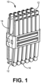
- Figs. 1-4B illustrate examples of an electrical connector 10 well suited for high voltage, e.g., over 200 volts.
- the electrical connector 10 has a female socket 12 at each end that is configured to receive a solid electrical conductor, e.g., a rectangular electrical bus bar (not shown) in each end of the connector.
- the connector has at least one pair of electrical contacts 14 at each end that are configured to receive the bus bars. As best shown in the exploded view of Fig. 2B , each of the electrical contacts 14 has a mesial or central base portion 16.
- a first plurality of elongate contact fingers 18A extends longitudinally from the base in a first direction and a second plurality of elongate contact fingers 18B extends longitudinally from the base portion 16 in a second direction opposite to the first direction.
- a mesial portion 20 of the contact fingers located closest to the base is canted or bent inwardly, i.e., toward a longitudinal central plane 22 through the electrical connector 10 (see Fig. 2A ) so that the contact fingers 18 are in compressive contact with the bus bars when they are inserted within the electrical connector 10.
- a distal potion or tip 24 at the free ends of the contact fingers 18 is canted outwardly away from the longitudinal central plane 22 to allow the bus bars to more easily be inserted between the contact fingers 18.
- the electrical connector also has a spring assembly 26 with a retaining band 28 that surrounds the bases 16 of the electrical contacts 14.
- the retaining band 28 secures the pair of electrical contacts 14 within the electrical connector 10.
- the spring assembly 26 further has a first plurality of elongate spring fingers 30A that extend longitudinally from the retaining band 28 in the first direction and a second plurality of elongate spring fingers 30B that extend longitudinally from the retaining band 28 in the second direction.
- the spring fingers 30 are configured so that they provide at least 90% of the contact force applied by the electrical connector 10 to the bus bars while the contact fingers 18 provide 10% or less of the of the contact force applied by the electrical connector 10 to the bus bars.
- the spring fingers 30 are bent inwardly at a greater angle than the contact fingers 18, thereby applying a pre-load force to the contact fingers 18.
- the inner contacts 14A are not identical to the outer contacts 14B and have a slightly different profile so that the outer contacts 14B will nest against the inner contacts 14A.
- the inner and outer contacts 14A, 14B on one side of the electrical connector 10 are identical to the corresponding inner and outer contacts 14A, 14B on the opposite side. This nesting of the inner and outer contacts 14A, 14B allows an outer side 32 of the inner contacts 14A to be in intimate contact with an inner side 34 of the outer contacts 14B. This nesting provides an effectively thicker electrical contact within the electrical connector 10 that allows a higher value of current to be safely conducted through the electrical connector 10.
- the nested inner and outer contacts 14A, 14B are also more flexible than contact fingers that have the same effective thickness and that are formed from a single layer of the same material. This flexibility allows the spring assembly 26 to apply 90% or more of the contact force which would not be possible with a single layer of the same material.
- the use of nested inner and outer contacts 14A, 14B also allows the electrical contacts 14 to be formed from a thinner material that is less expensive, more readily available, and easier to form than a thicker material.
- the embodiments of the electrical connector 10 shown in Figs 3A and 3B have two pairs of the electrical contacts while the embodiments of the electrical connector 10 shown in Figs 4A and 4B have three pairs of the electrical contacts.
- the number of contact fingers 18 in the embodiments of the electrical connector 10 may also vary as can be seen in Figs. 3A-4B .
- the electrical contacts 14 are made of a material that has a higher electrical conductivity value than the material forming the spring assembly 26.
- the electrical contacts 14 may be formed of Cl 10 copper alloy which offers high electrical and thermal conductivity.
- the spring assembly 26 may be made of SAE 301 1 ⁇ 2 hard stainless-steel alloy. Due to the higher conductivity of the electrical contacts 14, most of the current passing through the electrical connector 10 will pass through the electrical contacts 14 rather than the spring assembly 26. Therefore, the properties of the spring assembly 26 can be optimized for application of the contact force to the bus bars without consideration of current carrying capabilities. Since the electrical contacts 14 provide less than 10% of the spring force, most of the initial spring force will still be provided by the spring fingers 30 even if the contact fingers 18 relax due to heating because the spring fingers 30 are not as susceptible to relaxation due to heating as the copper contact fingers.
- the spring assembly 26 is integrally formed from a single piece of sheet metal and in other embodiments, the spring assembly 26 is made of two halves that are identical to each other.
- the base portions 16 of the contacts define tabs 36 that extend laterally from the base.
- the retaining band defines apertures in which these tabs are received within corresponding apertures 38 extending through the retaining band 28, thereby securing the electrical contacts within the electrical connector.
- the retaining band 28 may have attachment features 40, such as a dovetail features, which are arranged so that they match up when one end of the retaining band 28 is bent to join the other end of the retaining band 28.
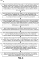
- a method 100 of manufacturing an electrical connector 10 is shown in the flow chart of Fig. 6 .
- the various steps of the method 100 are described below:
- STEP 102 FORM A PAIR OF ELECTRICAL CONTACTS FROM A SHEET OF A FIRST ELECTRICALLY CONDUCTIVE MATERIAL, EACH ELECTRICAL CONTACT IN THE PAIR OF ELECTRICAL CONTACTS HAVING A CENTRAL BASE, A FIRST PLURALITY OF ELONGATE CONTACT FINGERS EXTENDING LONGITUDINALLY FROM THE BASE IN A FIRST DIRECTION, AND A SECOND PLURALITY OF ELONGATE CONTACT FINGERS EXTENDING LONGITUDINALLY FROM THE BASE IN A SECOND DIRECTION OPPOSITE TO THE FIRST DIRECTION, includes forming a pair of electrical contacts 14 from a sheet of a first electrically conductive material, each electrical contact 14A, 14B in the pair of electrical contacts 14 having a central base portion 16, a first plurality of elongate contact fingers 18A extending longitudinally from the base portion 16 in a first direction, and a second plurality of elong
- STEP 104 BEND A PORTION OF AT LEAST ONE CONTACT FINGER OF THE FIRST AND SECOND PLURALITY OF ELONGATE CONTACT FINGERS SO THAT IT IS CANTED TOWARD A CENTERLINE OF THE ELECTRICAL CONNECTOR AND BENDING A TIP OF THE AT LEAST ONE CONTACT FINGER SO THAT IT IS CANTED AWAY FROM THE CENTERLINE OF THE ELECTRICAL CONNECTOR, includes bending a portion of at least one contact finger 18 of the first and second plurality of elongate contact fingers 18A, 18B so that it is canted toward a centerline or the longitudinal central plane 22 of the electrical connector 10 and bending a tip 24 of the at least one contact finger 18 so that it is canted away from the centerline or the longitudinal central plane 22 of the electrical connector 10;
- STEP 106 FORM A SPRING ASSEMBLY FROM A SHEET OF A SECOND ELECTRICALLY CONDUCTIVE MATERIAL, THE SPRING ASSEMBLY HAVING A RETAINING BAND, A FIRST PLURALITY OF ELONGATE SPRING FINGERS EXTENDING LONGITUDINALLY FROM THE RETAINING BAND IN THE FIRST DIRECTION, AND A SECOND PLURALITY OF ELONGATE SPRING FINGERS EXTENDING LONGITUDINALLY FROM THE RETAINING BAND IN THE SECOND DIRECTION, includes forming a spring assembly 26 from a sheet of a second electrically conductive material, the spring assembly 26 having a retaining band 28, a first plurality of spring fingers 30A, extending longitudinally from the retaining band 28 in the first direction, and a second plurality of spring fingers 30B extending longitudinally from the retaining band 28 in the second direction;
- STEP 108 WRAP THE RETAINING BAND AROUND THE BASES OF THE PAIR OF ELECTRICAL CONTACTS, THEREBY SECURING THE PAIR OF ELECTRICAL CONTACTS WITHIN THE ELECTRICAL CONNECTOR, includes wrapping the retaining band 28 around the bases 16 of the pair of electrical contacts 14, thereby securing the pair of electrical contacts 14 within the electrical connector 10;
- STEP 110 BEND A SPRING FINGER OF THE FIRST OR SECOND PLURALITY OF SPRING FINGERS INWARDLY SUCH THAT THE SPRING FINGER IS IN COMPRESSIVE CONTACT WITH AT LEAST ONE CONTACT FINGER OF THE FIRST AND SECOND PLURALITY OF ELONGATE CONTACT FINGERS, includes bending a spring finger 30 of the first or second plurality of spring fingers 30A, 30B inwardly such that the spring finger 30 is in compressive contact with at least one contact finger 18 of the first and second plurality of elongate contact fingers 18A, 18B;
- STEP 114 FORM A SECOND PAIR OF ELECTRICAL CONTACTS FROM A SHEET OF THE FIRST ELECTRICALLY CONDUCTIVE MATERIAL, WHEREIN EACH ELECTRICAL CONTACT IN THE SECOND PAIR OF ELECTRICAL CONTACTS HAVING A CENTRAL BASE, A FIRST PLURALITY OF ELONGATE CONTACT FINGERS EXTENDING LONGITUDINALLY FROM THE BASE IN THE FIRST DIRECTION, AND A SECOND PLURALITY OF ELONGATE CONTACT FINGERS EXTENDING LONGITUDINALLY FROM THE BASE IN THE SECOND DIRECTION, is an optional step that includes forming a second pair of electrical contacts 14B from a sheet of the first electrically conductive material, wherein each electrical contact 14 in the second pair of electrical contacts 14B having a central base portion 16, a first plurality of elongate contact fingers 18A extending longitudinally from the base portion 16 in the first direction, and a second pluralit
- STEP 116 BEND THE FIRST AND SECOND PAIRS OF ELECTRICAL CONTACTS SUCH THAT OUTWARDLY ORIENTED SURFACES OF THE SECOND PAIR OF CONTACTS ARE IN INTIMATE CONTACT WITH INWARDLY ORIENTED SURFACES OF THE FIRST PAIR OF CONTACTS, is an optional step that includes bending the first and second pairs of electrical contacts 14A, 14B such that outwardly oriented surfaces or outer sides 32 of the first pair of contacts 14A are in intimate contact with inwardly oriented surfaces or inner sides 34 of the second pair of contacts 14B.
- an electrical connector 10 suited for high voltage/current applications and a method 100 for manufacturing such an electrical connector is provided.
- the electrical connector 10 and the method 100 provide the benefit of an electrical connector that provides a consistent contact force in elevated temperature conditions and over the operating life of the electrical connector.
- the electrical connector 10 is smaller than prior art connector used in similar bus bar connecting applications when shown in the same scale, thereby providing the benefit of requiring less packaging space for the electrical connector 10.
Landscapes
- Coupling Device And Connection With Printed Circuit (AREA)
- Manufacturing Of Electrical Connectors (AREA)
Claims (13)
- Connecteur électrique (10) configuré pour interconnecter deux barres omnibus électriques, comprenant :une première paire de contacts électriques (14A) configurés pour recevoir les deux barres omnibus électriques, chaque contact électrique (14) dans la paire de contacts électriques (14A) ayant une base centrale (16), une première pluralité de doigts de contact allongés (18A) s'étendant longitudinalement à partir de la base (16) dans une première direction, et une seconde pluralité de doigts de contact allongés (18B) s'étendant longitudinalement à partir de la base (16) dans une seconde direction opposée à la première direction ;une seconde paire de contacts électriques (14B), dans lequel chaque contact électrique de la seconde paire de contacts électriques (14B) a une base centrale (16), une première pluralité de doigts de contact allongés (18A) s'étendant longitudinalement à partir de la base dans la première direction, et une seconde pluralité de doigts de contact allongés (18B) s'étendant longitudinalement à partir de la base (16) dans la seconde direction, dans lequel les surfaces orientées vers l'extérieur de la seconde paire de contacts (14B) ont un profil différent de celui des surfaces orientées vers l'intérieur de la première paire de contacts (14A) de telle sorte que la seconde paire de contacts (14B) s'emboîtent contre la première paire de contacts (14A), et dans lequel les surfaces orientées vers l'extérieur de la seconde paire de contacts (14B) sont en contact étroit avec les surfaces orientées vers l'intérieur de la première paire de contacts (14A) ; etun ensemble ressort (26) ayant une bande de retenue (28) entourant les bases (16) des première et seconde paires de contacts électriques (14A, 14B) et configuré pour fixer les première et seconde paires de contacts électriques (14A, 14B) à l'intérieur du connecteur électrique (10), l'ensemble ressort (26) ayant en outre une première pluralité de doigts à ressort allongés (30A) s'étendant longitudinalement à partir de la bande de retenue (28) dans la première direction, et une seconde pluralité de doigts à ressort allongés (30B) s'étendant longitudinalement à partir de la bande de retenue (28) dans la seconde direction, dans lequel un doigt à ressort (30) de la première ou de la seconde pluralité de doigts à ressort (30A, 30B) est en contact compressif avec au moins un doigt de contact de la première et de la seconde pluralité de doigts de contact allongés (18A, 18B) de la seconde paire de contacts électriques (14B) .
- Connecteur électrique (10) selon la revendication 1, dans lequel chaque doigt à ressort (30) de la première et de la seconde pluralité de doigts à ressort (30A, 30B) est en contact compressif avec au moins un doigt de contact (18) de la première et de la seconde pluralité de doigts de contact allongés (18A, 18B) .
- Connecteur électrique (10) selon la revendication 2, dans lequel une partie de l'au moins un doigt de contact est inclinée vers une ligne centrale (22) du connecteur électrique (10) et une pointe (24) de l'au moins un doigt de contact (18) est inclinée par rapport à la ligne centrale (22) du connecteur électrique (10).
- Connecteur électrique (10) selon l'une quelconque des revendications précédentes, dans lequel un premier matériau électriquement conducteur formant la première et la seconde paire de contacts électriques (14A, 14B) a une valeur de conductivité électrique plus élevée qu'un second matériau électriquement conducteur formant l'ensemble ressort (26).
- Connecteur électrique (10) selon la revendication 4, dans lequel le premier matériau est un alliage à base de cuivre.
- Connecteur électrique (10) selon la revendication 4 ou 5, dans lequel le second matériau est un alliage d'acier inoxydable.
- Connecteur électrique (10) selon l'une quelconque des revendications précédentes, dans lequel chaque contact électrique dans la première paire de contacts électriques (14A) est identique et dans lequel chaque contact électrique dans la seconde paire de contacts (14B) est identique.
- Connecteur électrique (10) selon l'une quelconque des revendications précédentes, dans lequel la bande de retenue (28) définit des éléments en queue d'aronde (40) pour fixer les extrémités de la bande de retenue (28) les unes aux autres.
- Connecteur électrique (10) selon la revendication 1, dans lequel les bases centrales (16) définissent des languettes (36) s'étendant latéralement à partir des bases centrales (16) et la bande de retenue (28) définit des ouvertures (38) dans lesquelles les languettes (36) sont reçues, fixant ainsi les première et seconde paires de contacts électriques (14A, 14B) à l'intérieur du connecteur électrique (10).
- Procédé (100) de formation d'un connecteur électrique (10) configuré pour interconnecter deux barres omnibus électriques, comprenant :la formation d'une première paire de contacts électriques (14A) à partir d'une feuille d'un premier matériau électriquement conducteur, chaque contact électrique de la paire de contacts électriques (14A) ayant une base centrale (16), une première pluralité de doigts de contact allongés (18A) s'étendant longitudinalement à partir de la base (16) dans une première direction, et une seconde pluralité de doigts de contact allongés (18B) s'étendant longitudinalement à partir de la base (16) dans une seconde direction opposée à la première direction ;la formation d'une seconde paire de contacts électriques (14B) à partir d'une feuille du premier matériau électriquement conducteur, dans lequel chaque contact électrique (14) de la seconde paire de contacts électriques (14B) a une base centrale (16), une première pluralité de doigts de contact allongés (18A) s'étendant longitudinalement à partir de la base (16) dans la première direction, et une seconde pluralité de doigts de contact allongés (18B) s'étendant longitudinalement à partir de la base (16) dans la seconde direction ;le pliage d'une partie d'au moins un doigt de contact (18) de la première et de la seconde pluralité de doigts de contact allongés (18A, 18B) de sorte qu'elle soit inclinée vers une ligne centrale (22) du connecteur électrique (10) et le pliage d'une pointe (24) de l'au moins un doigt de contact (18) de sorte qu'elle soit inclinée par rapport à la ligne centrale (22) du connecteur électrique (10), dans lequel les surfaces orientées vers l'extérieur de la seconde paire de contacts (14B) ont un profil différent que les surfaces orientées vers l'intérieur de la première paire de contacts (14A) ;l'agencement des première et seconde paires de contacts électriques (14A, 14B) de telle sorte que la seconde paire de contacts (14B) s'emboîtent contre la première paire de contacts (14A) et que les surfaces orientées vers l'extérieur de la seconde paire de contacts (14B) soient en contact intime avec les surfaces orientées vers l'intérieur de la première paire de contacts (14A) ;la formation d'un ensemble ressort (26) à partir d'une feuille d'un second matériau électriquement conducteur, l'ensemble ressort (26) ayant une bande de retenue (28), une première pluralité de doigts à ressort allongés (30A) s'étendant longitudinalement à partir de la bande de retenue (28) dans la première direction, et une seconde pluralité de doigts à ressort allongés (30B) s'étendant longitudinalement à partir de la bande de retenue (28) dans la seconde direction ;l'enroulement de la bande de retenue (28) autour des bases (16) des première et seconde paires de contacts électriques (14A, 14B), fixant ainsi les première et seconde paires de contacts électriques (14A, 14B) à l'intérieur du connecteur électrique (10) ; etle pliage d'un doigt à ressort (30) de la première ou de la seconde pluralité de doigts à ressort (30A, 30B) vers l'intérieur de telle sorte que le doigt à ressort (30) soit en contact de compression avec au moins un doigt de contact (18) de la première et de la seconde pluralité de doigts de contact allongés (18A, 18B) de la seconde paire de contacts électriques (14B) .
- Procédé (100) selon la revendication 10, comprenant également le pliage de chaque doigt à ressort (30) de la première et de la seconde pluralité de doigts à ressort (30) vers l'intérieur de telle sorte que chaque doigt à ressort (30) soit en contact compressif avec au moins un doigt de contact (18) de la première et de la seconde pluralité de doigts de contact allongés (18A, 18B).
- Procédé (100) selon la revendication 10 ou 11, dans lequel le premier matériau électriquement conducteur a une valeur de conductivité électrique supérieure à celle d'un second matériau électriquement conducteur formant l'ensemble ressort.
- Procédé (10) selon la revendication selon l'une quelconque des revendications 10 à 12, dans lequel les bases centrales (16) définissent des languettes (36) s'étendant latéralement à partir des bases centrales (16) et la bande de retenue (28) définit des ouvertures (38) dans lesquelles les languettes (36) sont reçues, fixant ainsi les première et seconde paires de contacts électriques (14A, 14B) à l'intérieur du connecteur électrique (10) .
Applications Claiming Priority (2)
| Application Number | Priority Date | Filing Date | Title |
|---|---|---|---|
| US202163155384P | 2021-03-02 | 2021-03-02 | |
| US17/568,109 US12003052B2 (en) | 2021-03-02 | 2022-01-04 | Female electrical bus bar connector and method of forming same |
Publications (2)
| Publication Number | Publication Date |
|---|---|
| EP4054009A1 EP4054009A1 (fr) | 2022-09-07 |
| EP4054009B1 true EP4054009B1 (fr) | 2024-10-16 |
Family
ID=80445676
Family Applications (1)
| Application Number | Title | Priority Date | Filing Date |
|---|---|---|---|
| EP22155622.8A Active EP4054009B1 (fr) | 2021-03-02 | 2022-02-08 | Connecteur électrique femelle de barre omnibus et son procédé de formation |
Country Status (3)
| Country | Link |
|---|---|
| US (1) | US12003052B2 (fr) |
| EP (1) | EP4054009B1 (fr) |
| CN (1) | CN115000729B (fr) |
Families Citing this family (3)
| Publication number | Priority date | Publication date | Assignee | Title |
|---|---|---|---|---|
| US20230057532A1 (en) * | 2020-02-13 | 2023-02-23 | Molex, Llc | Busbar connector |
| EP4220866B1 (fr) | 2022-01-26 | 2024-11-06 | Aptiv Technologies AG | Borne de puissance comportant une structure multicouche et ensemble de bornes de puissance ayant un nombre divers de couches |
| TW202418675A (zh) * | 2022-10-28 | 2024-05-01 | 大陸商安費諾商用電子產品(成都)有限公司 | 用於電連接器之端子、電連接器及其製造方法 |
Family Cites Families (13)
| Publication number | Priority date | Publication date | Assignee | Title |
|---|---|---|---|---|
| US3201556A (en) | 1963-07-19 | 1965-08-17 | Gen Electric | Self-aligning disconnect assembly |
| US6758702B2 (en) * | 2000-02-24 | 2004-07-06 | Fci Americas Technology, Inc. | Electrical connector with compression contacts |
| US7059059B1 (en) * | 2002-04-22 | 2006-06-13 | Ames Kenneth D | Combination level, plumb tool with single-hand engagement |
| US7104812B1 (en) * | 2005-02-24 | 2006-09-12 | Molex Incorporated | Laminated electrical terminal |
| EP2048746B1 (fr) * | 2007-08-13 | 2016-10-05 | Tyco Electronics Nederland B.V. | Système de connexion de barre de bus |
| US8303349B2 (en) * | 2009-05-22 | 2012-11-06 | Solaredge Technologies Ltd. | Dual compressive connector |
| US7892050B2 (en) * | 2009-06-17 | 2011-02-22 | Lear Corporation | High power fuse terminal with scalability |
| CN104242084B (zh) * | 2013-06-13 | 2018-08-14 | 通用电气公司 | 用于开关装置的管口、具有管口的开关装置及其方法 |
| US9705300B1 (en) * | 2016-01-07 | 2017-07-11 | General Electric Company | Electrical busway joint with laminated bracing system |
| US9800004B1 (en) * | 2016-05-04 | 2017-10-24 | Amphenol Corporation | Busbar connector assembly |
| CN107579370A (zh) * | 2017-09-04 | 2018-01-12 | 合肥家佳乐食品工业有限公司 | 一种用于插头的接线端子 |
| US11444399B2 (en) * | 2018-10-18 | 2022-09-13 | Fci Usa Llc | High reliability sliding power connector |
| CN111193126A (zh) | 2018-11-14 | 2020-05-22 | 泰科电子(上海)有限公司 | 导电端子和电连接器 |
-
2022
- 2022-01-04 US US17/568,109 patent/US12003052B2/en active Active
- 2022-02-08 EP EP22155622.8A patent/EP4054009B1/fr active Active
- 2022-03-01 CN CN202210198999.XA patent/CN115000729B/zh active Active
Also Published As
| Publication number | Publication date |
|---|---|
| US12003052B2 (en) | 2024-06-04 |
| CN115000729B (zh) | 2025-09-26 |
| EP4054009A1 (fr) | 2022-09-07 |
| US20220285872A1 (en) | 2022-09-08 |
| CN115000729A (zh) | 2022-09-02 |
Similar Documents
| Publication | Publication Date | Title |
|---|---|---|
| EP4054009B1 (fr) | Connecteur électrique femelle de barre omnibus et son procédé de formation | |
| CN101783456B (zh) | 用于高温环境的电连接器 | |
| CN105993099B (zh) | 具有增强夹持力的电气端子 | |
| CN109326913B (zh) | 高电流电气端子 | |
| JP5723695B2 (ja) | 雌端子 | |
| TW201445839A (zh) | 金屬彈片 | |
| JP5723694B2 (ja) | 雌端子 | |
| US9431721B2 (en) | Contact element | |
| JP5639101B2 (ja) | コネクタ端子用接触ばね | |
| US20140087602A1 (en) | Electrical terminal | |
| CN113013656A (zh) | 带有连接保持器的电端子组件 | |
| US11575225B2 (en) | Electrical connector | |
| JP2012054234A (ja) | 導電性接点構成 | |
| EP2893596A1 (fr) | Connecteur électrique et ensemble connecteur électrique | |
| US8734193B2 (en) | Connector | |
| CN110892590B (zh) | 用于大电流应用的电插塞触头和用于大电流应用的插塞连接器系统 | |
| CN105144487A (zh) | 直插式压力弹簧端子 | |
| CN118235300A (zh) | 连接器、连接器组件以及用于组装连接器组件的工具和方法 | |
| CN108736212B (zh) | 由至少两个部件组装成的接触端子 | |
| US11837825B2 (en) | Connector for bus bar plug assembly | |
| EP3567624A1 (fr) | Barre omnibus | |
| US20050009414A1 (en) | Contact element for an electrical plug connection | |
| WO2014096884A1 (fr) | Borne électrique et procédé de fabrication | |
| CN104241876A (zh) | 金属弹片 | |
| CA2714938C (fr) | Ressort de contact |
Legal Events
| Date | Code | Title | Description |
|---|---|---|---|
| PUAI | Public reference made under article 153(3) epc to a published international application that has entered the european phase |
Free format text: ORIGINAL CODE: 0009012 |
|
| STAA | Information on the status of an ep patent application or granted ep patent |
Free format text: STATUS: THE APPLICATION HAS BEEN PUBLISHED |
|
| AK | Designated contracting states |
Kind code of ref document: A1 Designated state(s): AL AT BE BG CH CY CZ DE DK EE ES FI FR GB GR HR HU IE IS IT LI LT LU LV MC MK MT NL NO PL PT RO RS SE SI SK SM TR |
|
| STAA | Information on the status of an ep patent application or granted ep patent |
Free format text: STATUS: REQUEST FOR EXAMINATION WAS MADE |
|
| 17P | Request for examination filed |
Effective date: 20221114 |
|
| RBV | Designated contracting states (corrected) |
Designated state(s): AL AT BE BG CH CY CZ DE DK EE ES FI FR GB GR HR HU IE IS IT LI LT LU LV MC MK MT NL NO PL PT RO RS SE SI SK SM TR |
|
| RAP3 | Party data changed (applicant data changed or rights of an application transferred) |
Owner name: APTIV TECHNOLOGIES LIMITED |
|
| GRAP | Despatch of communication of intention to grant a patent |
Free format text: ORIGINAL CODE: EPIDOSNIGR1 |
|
| STAA | Information on the status of an ep patent application or granted ep patent |
Free format text: STATUS: GRANT OF PATENT IS INTENDED |
|
| INTG | Intention to grant announced |
Effective date: 20240201 |
|
| GRAJ | Information related to disapproval of communication of intention to grant by the applicant or resumption of examination proceedings by the epo deleted |
Free format text: ORIGINAL CODE: EPIDOSDIGR1 |
|
| STAA | Information on the status of an ep patent application or granted ep patent |
Free format text: STATUS: REQUEST FOR EXAMINATION WAS MADE |
|
| P01 | Opt-out of the competence of the unified patent court (upc) registered |
Effective date: 20240325 |
|
| INTC | Intention to grant announced (deleted) | ||
| RAP1 | Party data changed (applicant data changed or rights of an application transferred) |
Owner name: APTIV TECHNOLOGIES AG |
|
| GRAS | Grant fee paid |
Free format text: ORIGINAL CODE: EPIDOSNIGR3 |
|
| STAA | Information on the status of an ep patent application or granted ep patent |
Free format text: STATUS: GRANT OF PATENT IS INTENDED |
|
| GRAP | Despatch of communication of intention to grant a patent |
Free format text: ORIGINAL CODE: EPIDOSNIGR1 |
|
| INTG | Intention to grant announced |
Effective date: 20240624 |
|
| GRAA | (expected) grant |
Free format text: ORIGINAL CODE: 0009210 |
|
| STAA | Information on the status of an ep patent application or granted ep patent |
Free format text: STATUS: THE PATENT HAS BEEN GRANTED |
|
| RAP3 | Party data changed (applicant data changed or rights of an application transferred) |
Owner name: APTIV TECHNOLOGIES AG |
|
| AK | Designated contracting states |
Kind code of ref document: B1 Designated state(s): AL AT BE BG CH CY CZ DE DK EE ES FI FR GB GR HR HU IE IS IT LI LT LU LV MC MK MT NL NO PL PT RO RS SE SI SK SM TR |
|
| REG | Reference to a national code |
Ref country code: GB Ref legal event code: FG4D |
|
| REG | Reference to a national code |
Ref country code: CH Ref legal event code: EP Ref country code: DE Ref legal event code: R096 Ref document number: 602022006752 Country of ref document: DE |
|
| REG | Reference to a national code |
Ref country code: IE Ref legal event code: FG4D |
|
| REG | Reference to a national code |
Ref country code: LT Ref legal event code: MG9D |
|
| REG | Reference to a national code |
Ref country code: NL Ref legal event code: MP Effective date: 20241016 |
|
| REG | Reference to a national code |
Ref country code: AT Ref legal event code: MK05 Ref document number: 1733725 Country of ref document: AT Kind code of ref document: T Effective date: 20241016 |
|
| PG25 | Lapsed in a contracting state [announced via postgrant information from national office to epo] |
Ref country code: NL Free format text: LAPSE BECAUSE OF FAILURE TO SUBMIT A TRANSLATION OF THE DESCRIPTION OR TO PAY THE FEE WITHIN THE PRESCRIBED TIME-LIMIT Effective date: 20241016 |
|
| PG25 | Lapsed in a contracting state [announced via postgrant information from national office to epo] |
Ref country code: NL Free format text: LAPSE BECAUSE OF FAILURE TO SUBMIT A TRANSLATION OF THE DESCRIPTION OR TO PAY THE FEE WITHIN THE PRESCRIBED TIME-LIMIT Effective date: 20241016 |
|
| PG25 | Lapsed in a contracting state [announced via postgrant information from national office to epo] |
Ref country code: IS Free format text: LAPSE BECAUSE OF FAILURE TO SUBMIT A TRANSLATION OF THE DESCRIPTION OR TO PAY THE FEE WITHIN THE PRESCRIBED TIME-LIMIT Effective date: 20250216 Ref country code: HR Free format text: LAPSE BECAUSE OF FAILURE TO SUBMIT A TRANSLATION OF THE DESCRIPTION OR TO PAY THE FEE WITHIN THE PRESCRIBED TIME-LIMIT Effective date: 20241016 Ref country code: PT Free format text: LAPSE BECAUSE OF FAILURE TO SUBMIT A TRANSLATION OF THE DESCRIPTION OR TO PAY THE FEE WITHIN THE PRESCRIBED TIME-LIMIT Effective date: 20250217 |
|
| PG25 | Lapsed in a contracting state [announced via postgrant information from national office to epo] |
Ref country code: FI Free format text: LAPSE BECAUSE OF FAILURE TO SUBMIT A TRANSLATION OF THE DESCRIPTION OR TO PAY THE FEE WITHIN THE PRESCRIBED TIME-LIMIT Effective date: 20241016 |
|
| PG25 | Lapsed in a contracting state [announced via postgrant information from national office to epo] |
Ref country code: BG Free format text: LAPSE BECAUSE OF FAILURE TO SUBMIT A TRANSLATION OF THE DESCRIPTION OR TO PAY THE FEE WITHIN THE PRESCRIBED TIME-LIMIT Effective date: 20241016 |
|
| PG25 | Lapsed in a contracting state [announced via postgrant information from national office to epo] |
Ref country code: ES Free format text: LAPSE BECAUSE OF FAILURE TO SUBMIT A TRANSLATION OF THE DESCRIPTION OR TO PAY THE FEE WITHIN THE PRESCRIBED TIME-LIMIT Effective date: 20241016 |
|
| PG25 | Lapsed in a contracting state [announced via postgrant information from national office to epo] |
Ref country code: NO Free format text: LAPSE BECAUSE OF FAILURE TO SUBMIT A TRANSLATION OF THE DESCRIPTION OR TO PAY THE FEE WITHIN THE PRESCRIBED TIME-LIMIT Effective date: 20250116 |
|
| PG25 | Lapsed in a contracting state [announced via postgrant information from national office to epo] |
Ref country code: GR Free format text: LAPSE BECAUSE OF FAILURE TO SUBMIT A TRANSLATION OF THE DESCRIPTION OR TO PAY THE FEE WITHIN THE PRESCRIBED TIME-LIMIT Effective date: 20250117 Ref country code: AT Free format text: LAPSE BECAUSE OF FAILURE TO SUBMIT A TRANSLATION OF THE DESCRIPTION OR TO PAY THE FEE WITHIN THE PRESCRIBED TIME-LIMIT Effective date: 20241016 Ref country code: LV Free format text: LAPSE BECAUSE OF FAILURE TO SUBMIT A TRANSLATION OF THE DESCRIPTION OR TO PAY THE FEE WITHIN THE PRESCRIBED TIME-LIMIT Effective date: 20241016 |
|
| PG25 | Lapsed in a contracting state [announced via postgrant information from national office to epo] |
Ref country code: PL Free format text: LAPSE BECAUSE OF FAILURE TO SUBMIT A TRANSLATION OF THE DESCRIPTION OR TO PAY THE FEE WITHIN THE PRESCRIBED TIME-LIMIT Effective date: 20241016 |
|
| PG25 | Lapsed in a contracting state [announced via postgrant information from national office to epo] |
Ref country code: RS Free format text: LAPSE BECAUSE OF FAILURE TO SUBMIT A TRANSLATION OF THE DESCRIPTION OR TO PAY THE FEE WITHIN THE PRESCRIBED TIME-LIMIT Effective date: 20250116 |
|
| PG25 | Lapsed in a contracting state [announced via postgrant information from national office to epo] |
Ref country code: SM Free format text: LAPSE BECAUSE OF FAILURE TO SUBMIT A TRANSLATION OF THE DESCRIPTION OR TO PAY THE FEE WITHIN THE PRESCRIBED TIME-LIMIT Effective date: 20241016 |
|
| PG25 | Lapsed in a contracting state [announced via postgrant information from national office to epo] |
Ref country code: DK Free format text: LAPSE BECAUSE OF FAILURE TO SUBMIT A TRANSLATION OF THE DESCRIPTION OR TO PAY THE FEE WITHIN THE PRESCRIBED TIME-LIMIT Effective date: 20241016 |
|
| REG | Reference to a national code |
Ref country code: DE Ref legal event code: R097 Ref document number: 602022006752 Country of ref document: DE |
|
| PG25 | Lapsed in a contracting state [announced via postgrant information from national office to epo] |
Ref country code: EE Free format text: LAPSE BECAUSE OF FAILURE TO SUBMIT A TRANSLATION OF THE DESCRIPTION OR TO PAY THE FEE WITHIN THE PRESCRIBED TIME-LIMIT Effective date: 20241016 |
|
| PG25 | Lapsed in a contracting state [announced via postgrant information from national office to epo] |
Ref country code: RO Free format text: LAPSE BECAUSE OF FAILURE TO SUBMIT A TRANSLATION OF THE DESCRIPTION OR TO PAY THE FEE WITHIN THE PRESCRIBED TIME-LIMIT Effective date: 20241016 |
|
| PG25 | Lapsed in a contracting state [announced via postgrant information from national office to epo] |
Ref country code: SK Free format text: LAPSE BECAUSE OF FAILURE TO SUBMIT A TRANSLATION OF THE DESCRIPTION OR TO PAY THE FEE WITHIN THE PRESCRIBED TIME-LIMIT Effective date: 20241016 |
|
| PG25 | Lapsed in a contracting state [announced via postgrant information from national office to epo] |
Ref country code: CZ Free format text: LAPSE BECAUSE OF FAILURE TO SUBMIT A TRANSLATION OF THE DESCRIPTION OR TO PAY THE FEE WITHIN THE PRESCRIBED TIME-LIMIT Effective date: 20241016 |
|
| PG25 | Lapsed in a contracting state [announced via postgrant information from national office to epo] |
Ref country code: IT Free format text: LAPSE BECAUSE OF FAILURE TO SUBMIT A TRANSLATION OF THE DESCRIPTION OR TO PAY THE FEE WITHIN THE PRESCRIBED TIME-LIMIT Effective date: 20241016 |
|
| PLBE | No opposition filed within time limit |
Free format text: ORIGINAL CODE: 0009261 |
|
| STAA | Information on the status of an ep patent application or granted ep patent |
Free format text: STATUS: NO OPPOSITION FILED WITHIN TIME LIMIT |
|
| PG25 | Lapsed in a contracting state [announced via postgrant information from national office to epo] |
Ref country code: SE Free format text: LAPSE BECAUSE OF FAILURE TO SUBMIT A TRANSLATION OF THE DESCRIPTION OR TO PAY THE FEE WITHIN THE PRESCRIBED TIME-LIMIT Effective date: 20241016 |
|
| PG25 | Lapsed in a contracting state [announced via postgrant information from national office to epo] |
Ref country code: MC Free format text: LAPSE BECAUSE OF FAILURE TO SUBMIT A TRANSLATION OF THE DESCRIPTION OR TO PAY THE FEE WITHIN THE PRESCRIBED TIME-LIMIT Effective date: 20241016 |
|
| 26N | No opposition filed |
Effective date: 20250717 |
|
| REG | Reference to a national code |
Ref country code: CH Ref legal event code: PL |
|
| PG25 | Lapsed in a contracting state [announced via postgrant information from national office to epo] |
Ref country code: LU Free format text: LAPSE BECAUSE OF NON-PAYMENT OF DUE FEES Effective date: 20250208 |
|
| PG25 | Lapsed in a contracting state [announced via postgrant information from national office to epo] |
Ref country code: CH Free format text: LAPSE BECAUSE OF NON-PAYMENT OF DUE FEES Effective date: 20250228 |
|
| REG | Reference to a national code |
Ref country code: BE Ref legal event code: MM Effective date: 20250228 |
|
| PG25 | Lapsed in a contracting state [announced via postgrant information from national office to epo] |
Ref country code: BE Free format text: LAPSE BECAUSE OF NON-PAYMENT OF DUE FEES Effective date: 20250228 |
|
| PG25 | Lapsed in a contracting state [announced via postgrant information from national office to epo] |
Ref country code: IE Free format text: LAPSE BECAUSE OF NON-PAYMENT OF DUE FEES Effective date: 20250208 |
|
| PGFP | Annual fee paid to national office [announced via postgrant information from national office to epo] |
Ref country code: GB Payment date: 20260113 Year of fee payment: 5 |
|
| PGFP | Annual fee paid to national office [announced via postgrant information from national office to epo] |
Ref country code: DE Payment date: 20260121 Year of fee payment: 5 |
|
| PGFP | Annual fee paid to national office [announced via postgrant information from national office to epo] |
Ref country code: FR Payment date: 20260109 Year of fee payment: 5 |