EP4054302B1 - Anbaudrehpflug - Google Patents
Anbaudrehpflug Download PDFInfo
- Publication number
- EP4054302B1 EP4054302B1 EP20800864.9A EP20800864A EP4054302B1 EP 4054302 B1 EP4054302 B1 EP 4054302B1 EP 20800864 A EP20800864 A EP 20800864A EP 4054302 B1 EP4054302 B1 EP 4054302B1
- Authority
- EP
- European Patent Office
- Prior art keywords
- axis
- plow
- coupling element
- rotation
- depth adjustment
- Prior art date
- Legal status (The legal status is an assumption and is not a legal conclusion. Google has not performed a legal analysis and makes no representation as to the accuracy of the status listed.)
- Active
Links
Images



Classifications
-
- A—HUMAN NECESSITIES
- A01—AGRICULTURE; FORESTRY; ANIMAL HUSBANDRY; HUNTING; TRAPPING; FISHING
- A01B—SOIL WORKING IN AGRICULTURE OR FORESTRY; PARTS, DETAILS, OR ACCESSORIES OF AGRICULTURAL MACHINES OR IMPLEMENTS, IN GENERAL
- A01B3/00—Ploughs with fixed plough-shares
- A01B3/46—Ploughs supported partly by tractor and partly by their own wheels
- A01B3/464—Alternating ploughs with frame rotating about a horizontal axis, e.g. turn-wrest ploughs
Definitions
- the invention relates to a mounted reversible plough according to the preamble of patent claim 1.
- Such a mounted reversible plough is in EN 10 2012 103 667 A1 revealed.
- the GB 2 003 012 A discloses another mounted reversible plough in which the support wheel is arranged on the plough frame via a fastening device and can be adjusted to different working depths by means of a working depth adjustment device.
- This mounted reversible plough comprises a plough frame to which plough bodies are attached on two opposite sides.
- the plough frame can be turned around a horizontal turning axis, which essentially points in the direction of travel, relative to a headstock by means of at least one turning cylinder, so that either side of the plough bodies can be used for soil cultivation.
- the headstock is attached to the front end of the plough frame and is used to couple the mounted reversible plough to an agricultural tractor.
- the mounted reversible plow also includes a support wheel arranged on a wheel arm, which in turn is arranged on the plow frame via a fastening device.
- the fastening device includes a rotation axis that is transverse to the turning axis, a working depth adjustment device, a switching mechanism and a releasable locking device.
- the working depth adjustment device on this mounted reversible plow is designed as a hydraulic cylinder and the rotation axis as a continuous pivot shaft, with the pivot shaft being transverse to the direction of travel.
- the fastening device is therefore used to attach the support wheel to the plow frame and to adjust it relative to the plow frame.
- the wheel arm is pivotally connected to the end of the pivot axis facing away from the plough frame, so that the support wheel can be adjusted to both working positions on opposite sides of the plough frame by means of the working depth adjustment device.
- the support wheel pivots around the axis of rotation via the wheel arm.
- the working depth adjustment device on this mounted reversible plough is connected to the support wheel via the continuous pivot shaft.
- the releasable locking device is provided to remove the working depth adjustment device from the operative connection with the support wheel.
- the coupling between The working depth adjustment device and wheel arm, which is ensured by the swivel shaft on this mounted reversible plough, can be removed by releasing the locking device so that the wheel arm can swivel freely around the pivot axis on the plough frame.
- the locking device on this mounted reversible plough is designed as a pin connection.
- the wheel arm is also attached to the pivot axis via the reversing mechanism.
- the reversing mechanism has a joint axis that extends transversely to the pivot axis, around which the wheel arm can be pivoted into a transport position relative to the pivot axis. To do this, it is necessary to release the locking device on this mounted reversible plough.
- the object underlying the invention is therefore to provide a mounted reversible plough with an improved fastening device for simplified movement of the support wheel between working and transport positions.
- the fastening device comprises a coupling element, preferably rotatably attached to the axis of rotation, and that the working depth adjustment member is attached on the one hand to the plough frame and on the other hand to the coupling element and the Locking device is arranged between the wheel arm and the coupling element.
- the invention makes use of the knowledge that the separation of the locking device and the switching mechanism with the aid of the coupling element according to the invention makes it considerably easier to move the support arm between the working and transport positions.
- the locking device and the switching mechanism can be operated in series, so that the support arm only needs to be moved and held in one direction at a time when changing between the working and transport positions.
- the operation of the switching mechanism and the locking device is also made easier.
- the locking device comprises a locking bolt arranged on the wheel arm or coupling element and a receptacle for the locking bolt on the coupling element or wheel arm.
- the locking bolt can therefore be arranged either on the wheel arm or on the coupling element, with the receptacle being provided on the other component.
- the locking bolt can be displaced against a spring force, so that the locking bolt is held in the locking position in the receptacle by means of the spring force.
- the spring force can be overcome manually, preferably without tools, so that the locking device can be released by hand by the user.
- the locking bolt can have an easily accessible handle and/or attachment for a tool.
- an insertion aid is arranged in the area of the mount on the coupling element or on the wheel arm, so that the locking bolt can be inserted into the mount by means of the working depth adjustment element.
- the working depth adjustment element is designed to move the coupling element in relation to the wheel arm, preferably around the axis of rotation, on a circular path, so that the locking bolt and the mount can be guided towards each other.
- the insertion aid can be designed as a guide plate, so that the bolt is deflected and engages in the mount, i.e. locked. It is particularly advantageous here that the user can effortlessly couple the wheel arm to the working depth adjustment element without moving it by hand. He therefore does not come into contact with the wheel arm or the support wheel, which are sometimes very dirty. As a result of this development, the support wheel can be moved from the transport position to the working position at least partially by remote control.
- the working depth adjustment element is designed as a hydraulic cylinder.
- the hydraulic cylinder can be connected to a control unit of the agricultural tractor so that the working depth of the mounted reversible plough can be conveniently adjusted from the driver's cab of the tractor.
- the working depth adjustment element is designed as a length-adjustable adjustment element and/or, preferably hydraulic, damper.
- the length-adjustable adjustment element can be designed as a mechanical stop element which can be caught in a catch on the wheel arm.
- the adjustment element can be designed as a spindle so that the wheel arm is held at an adjustable distance and thus the support wheel is adjustable in height.
- the preferably hydraulic damper can be designed as a Hydraulic cylinders must be designed with at least one piston bore so that a slow exchange of oil takes place between the piston and rod side, thus ensuring a dampened movement of the piston rod.
- the switching mechanism comprises a locking pin and at least one receptacle for the locking pin in the working position and in the transport position of the wheel arm, wherein at least one receptacle can be brought into line with at least one hole in and/or next to the axis of rotation, so that the wheel arm can be fixed in the working position or the transport position relative to the articulation axis by means of the locking pin. Consequently, the switching mechanism for the working position and the transport position equally has a corresponding pair of receptacle and hole by means of which the wheel arm is held in one or the other position with the aid of the locking pin. As a result of this development, a switching mechanism that is particularly easy to operate is created.
- the support arm is pivoted about the joint axis by approximately 90 degrees in relation to the axis of rotation in the transport position. Since the plow frame is only turned by 90 degrees in relation to the working positions in the transport position, this further development ensures that the support wheel is arranged so as to be movable about an upright axis under the plow frame.
- the support wheel is thus designed to follow the movements of the mounted reversible plow or the agricultural tractor.
- a tool attachment is provided on the reversing mechanism designed so that the support arm can be moved between the working position and the transport position using a tool.
- the tool attachment can be designed as a wrench flat for a tool designed as an open-end wrench.
- the mounted reversible plough according to the invention is further advantageously further developed in that the working depth adjustment member is connected in an articulated manner to the plough frame and in an articulated manner to the free end of the coupling element, preferably facing away from the axis of rotation.
- This arrangement creates particularly favorable force ratios, so that the working depth adjustment member can be made lightweight.
- the wheel arm is releasably locked to the coupling element in the working position by means of the locking device.
- an advantageous development of the mounted reversible plow according to the invention provides that the working depth adjustment element and the support wheel can be brought out of operative connection by means of a released locking device between the wheel arm and the coupling element.
- the coupling between the wheel arm and the working depth adjustment element via the coupling element is thus canceled and the wheel arm can be pivoted about the joint axis by using the reversing mechanism.
- the plough frame in the transport position by means of the at least one The turning cylinder can be rotated by approximately 90 degrees relative to the headstock so that the support wheel under the plough frame assumes a following position that is decoupled from the working depth adjustment device and can be freely pivoted about the axis of rotation.
- the plough bodies point upwards so that the mounted reversible plough can be conveniently steered behind the agricultural tractor via the support wheel in the following position.
- the plough frame is supported on the support wheel via the fastening device so that the mounted reversible plough is only partially carried by the tractor.
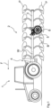
- a mounted reversible plough 2 in working position mounted behind an agricultural tractor 1 is in Fig.1
- the mounted reversible plough 2 comprises a plough frame 3 at the front end of which a mounting bracket 4 is arranged, via which the mounted reversible plough 2 is attached to the tractor 1.
- the Mounted reversible plough 2 a first embodiment of a fastening device 5 on which a support wheel 6 is arranged on the plough frame 3.
- the plough frame 3 can be turned relative to the headstock 4 by means of a turning cylinder arranged between the plough frame 3 and the headstock 4 about a turning axis W lying essentially in the direction of travel F.
- Fig.1 shows, plow bodies P are arranged on two opposite sides of the plow frame 3, so that by means of the turning cylinder one of the two rows of plow bodies P can be brought into contact with the ground in the working position of the mounted reversible plow 2.
- the support wheel 6 arranged on the plow frame 3 via the fastening device 5 can be brought to different heights relative to the plow frame 3 by means of the fastening device 5 and rolls on the preferably unworked soil B, so that the mounted reversible plow 2 or the plow bodies P in contact with the ground are guided at the working depth in the soil B.
- the fastening device 5 comprises a rotation axis D which lies transversely to the turning axis W and which, in the working position of the mounted reversible plow 2, extends essentially horizontally, just like the turning axis W.
- the fastening device 5 comprises a working depth adjustment member 7, a switching mechanism 8, a releasable locking device 9 and a coupling element 10.
- the support wheel 6 is pivotally connected to the rotation axis D via a wheel arm 11.
- the support wheel 6 In order to pivot the support wheel 6 about the rotation axis D into both working positions on opposite sides of the plow frame 3, the support wheel 6 is operatively connected to the working depth adjustment member 7, which in this first embodiment is designed as an adjustment element designed as a spindle 7.1 and a hydraulic damper 7.2.
- the operative connection between the support wheel 6 and the working depth adjustment element 7 is established by the interaction of the locking device 9 between the wheel arm 11 and the coupling element 10.
- the hydraulic damper 7.2 of the working depth adjustment device 7 is attached in particular via the fastening device on the one hand to the Fig.2 not shown plow frame 3 and on the other hand at the end of the coupling element 10 facing away from the axis of rotation D.
- the coupling element 10 is rotatably attached to the axis of rotation D and detachably coupled to the wheel arm 11 via the locking device 9, so that the support wheel 6 can be brought into the two working positions by means of the working depth adjustment member 7 via the coupling element 10.
- this first embodiment of the fastening device 5 has the variable-length spindle 7.1, the length of which can be adjusted in a known manner.
- the spindle 7.1 is caught in a catch pawl 11.1 attached to the wheel arm 11 and thus limits the pivoting movement of the wheel arm 11 upwards around the axis of rotation D, thus effectively the height of the support wheel 6 relative to the plough frame 3 and thus the working depth of the plough bodies P.
- the spindle 7.1 is disengaged from the catch pawl 11.1 so that the wheel arm 11 can pivot around the axis of rotation D to the other working side of the plough frame 3.
- the pivoting movement is dampened by the hydraulic damper 7.2, which is designed as a cylinder with a piston bore for a slower oil exchange between the cylinder sides.
- the locking device 9 comprises a locking bolt 9.1 arranged on the wheel arm 11 and displaceable against a spring force f and a receptacle 9.2 on the coupling element 10 corresponding to the locking bolt 9.1.
- a reverse arrangement of the locking bolt 9.1 and receptacle 9.2 is also conceivable.
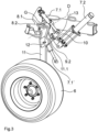
- the locking bolt 9.1 is in the Fig.2 shown working position of the first embodiment of the Fastening device 5 is received in the holder 9.2 and is held securely in place in the holder 9.2 by means of the spring force f, so that the support arm 11 and the coupling element 10 are reliably connected to one another in a form-fitting manner and can pivot together about the axis of rotation D.
- the locking bolt 9.1 has a handle 12 protruding through a sheet of the switching mechanism 8, by means of which the locking bolt 9.1 can be moved out of the holder 9.2 by hand against the spring force f, so that the locking device 9 is released and the support wheel 6 is brought out of the operative connection with the working depth adjustment element 7.
- the support arm 11 can be pivoted about an articulated axis G of the switching mechanism 8 extending transversely to the axis of rotation D relative to the axis of rotation D into a transport position, as shown in Fig.5 and 6 is shown.
- Fig.3 the first embodiment of the fastening device 5 can be seen in an intermediate position in which the locking device 9 is released. Since the wheel arm 11 is no longer locked to the coupling element 10 via the locking bolt 9.1 in the holder 9.2, the wheel arm 11 pivots downwards about the axis of rotation D under the influence of gravity and thus provides a view of the holder 9.2 on the coupling element 10. It can also be seen that none of the spindles 7.1, 7.1' is in engagement with the catch 11.1 and thus the wheel arm 11 can pivot freely about the axis of rotation D. In the area of the holder 9.2, an insertion aid designed as a guide plate 13 is arranged on the coupling element 10.
- the locking bolt 9.2 is deflected against the spring force f when the wheel arm 11 is pivoted relative to the coupling element 10 or vice versa, so that when the wheel arm 11 and the coupling element 10 are in the same pivot position relative to the axis of rotation D, the locking bolt 9.2 can be inserted into the receptacle 9.2.
- a second embodiment of the fastening device 5 can be seen from the rear, with the working depth adjustment element 7 being designed as a hydraulic cylinder 7.3.
- the spindles 7.1, 7.1' and the hydraulic damper 7.2, as well as the catch pawl 11.1 on the wheel arm 11 are omitted in the second Design of the fastening device 5 and are replaced by the hydraulic cylinder 7.3.
- the other components remain the same and are marked with the same reference numerals.
- the coupling element 10 can be pivoted remotely about the axis of rotation D by means of the hydraulic cylinder 7.3, which is arranged on the one hand in an articulated manner on the plow frame 3 and on the other hand in an articulated manner on the free end of the coupling element 10 facing away from the axis of rotation D.
- the working depth adjustment element 7 designed as a hydraulic cylinder 7.3
- the coupling element 10 can thus be brought into the same pivoting position relative to the axis of rotation D as the wheel arm 11, so that the locking bolt 9.2 can be inserted into the holder 9.2 via the insertion aid designed as a guide plate 13 in the manner described above.
- the support wheel 6 can be adjusted in height relative to the plow frame 3 and thus regulated in terms of working depth via the operative connection to the hydraulic cylinder 7.3, which exists between the wheel arm 11 and the coupling element 10 by means of the locking device 9. In the working position, the wheel arm 11 is therefore releasably locked to the coupling element 10 by means of the locking device 9.
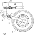
- the switching mechanism 8 In order to move the wheel arm 11 from the working position into the transport position pivoted by approximately 90 degrees relative to the rotation axis D by means of the joint axis G, as shown in Fig.5 shown, the switching mechanism 8 is provided.
- the switching mechanism 8 comprises a locking pin 8.1 and a locking pin holder 8.2 in the working position and in the transport position of the support arm 11.
- either the locking pin holder 8.2 for the working position or for the transport position is aligned with a hole in the axis of rotation D, so that by inserting the locking pin 8.1 into the pair of locking pin holder 8.2 and hole, the support arm 11 can be fixed either in the working position or the transport position in relation to the joint axis G.
- the hole to be aligned with the locking pin holder 8.2 can also be provided next to the axis of rotation.
- the movement of the wheel arm 11 from the working position according to Fig.1 , 2 and 4 into the transport position according to Fig.5 and 6 is carried out as follows: First, the locking device 9 between the wheel arm 11 and the coupling element 10 is to be released by deflecting the locking bolt 9.1 using the handle 12 against the spring force f, so that the working depth adjustment element 7 and the support wheel 6 are no longer connected. The wheel arm 11 then pivots into the position shown in Fig.3 shown intermediate position. The wheel arm 11 is fixed by means of the locking pin 8.1 relative to the rotation axis D about the joint axis G. The locking pin 8.1 must then be removed from the locking pin holder 8.2 for the working position, which was in line with a corresponding hole in the rotation axis D.
- the wheel arm 11 can now pivot relative to the rotation axis D about the joint axis G.
- the locking pin holder 8.2 for the transport position is aligned with the hole in the rotation axis D, so that the locking pin 8.1 can be inserted again.
- a tool attachment (not shown) designed as a wrench surface can be formed on the switching mechanism 8, via which the wheel arm 11 can be moved between the working position and the transport position using a tool designed, for example, as an open-end wrench, i.e. the pivoting of the wheel arm 11 by approximately 90 degrees can be carried out in an easier manner.
- the wheel arm 11 By reinserting the locking pin 8.1, the wheel arm 11 is in the position shown in Fig.5 shown position relative to the axis of rotation D around the articulation axis G. If the plough frame 3 is now brought into a position rotated by approximately 90 degrees around the turning axis W relative to the headstock 4 by means of the turning cylinder, as shown in Fig.6 As shown, the support wheel 6 is located under the plough frame 3 in a following position which is decoupled from the working depth adjustment element 7 and can be freely pivoted about the axis of rotation D. The mounted reversible plough 2 can thus follow steering maneuvers of the agricultural tractor 1, since the plough frame 3 is supported on the support wheel 6 which can be pivoted about the axis of rotation D.
Landscapes
- Life Sciences & Earth Sciences (AREA)
- Engineering & Computer Science (AREA)
- Mechanical Engineering (AREA)
- Soil Sciences (AREA)
- Environmental Sciences (AREA)
- Soil Working Implements (AREA)
Applications Claiming Priority (2)
| Application Number | Priority Date | Filing Date | Title |
|---|---|---|---|
| DE102019129988.8A DE102019129988A1 (de) | 2019-11-07 | 2019-11-07 | Anbaudrehpflug |
| PCT/EP2020/080616 WO2021089446A1 (de) | 2019-11-07 | 2020-11-02 | Anbaudrehpflug |
Publications (3)
| Publication Number | Publication Date |
|---|---|
| EP4054302A1 EP4054302A1 (de) | 2022-09-14 |
| EP4054302C0 EP4054302C0 (de) | 2024-08-14 |
| EP4054302B1 true EP4054302B1 (de) | 2024-08-14 |
Family
ID=73059890
Family Applications (1)
| Application Number | Title | Priority Date | Filing Date |
|---|---|---|---|
| EP20800864.9A Active EP4054302B1 (de) | 2019-11-07 | 2020-11-02 | Anbaudrehpflug |
Country Status (4)
| Country | Link |
|---|---|
| EP (1) | EP4054302B1 (pl) |
| DE (1) | DE102019129988A1 (pl) |
| PL (1) | PL4054302T3 (pl) |
| WO (1) | WO2021089446A1 (pl) |
Families Citing this family (3)
| Publication number | Priority date | Publication date | Assignee | Title |
|---|---|---|---|---|
| DE102021115252B4 (de) | 2021-06-14 | 2025-07-10 | Amazonen-Werke H. Dreyer SE & Co. KG | Aufsatteldrehpflug mit verbessertem Drehwerk |
| EP4282236A1 (en) * | 2022-05-25 | 2023-11-29 | CNH Industrial Sweden AB | Agricultural plough |
| CN118057985B (zh) * | 2024-04-19 | 2024-07-16 | 高密德隆汽车配件制造有限公司 | 一种翻转犁用限深行走两用机构 |
Family Cites Families (5)
| Publication number | Priority date | Publication date | Assignee | Title |
|---|---|---|---|---|
| NL7808549A (nl) * | 1977-08-26 | 1979-02-28 | Rabewerk Clausing Heinrich | Meerscharige aanbouwdraaiploeg. |
| DE2919362A1 (de) * | 1979-05-14 | 1980-11-27 | Rudolf Ing Grad Steigerwald | Drehwerkvorrichtung mit abstuetzvorrichtung, kippausgleich und klappeinrichtung des pflugbaumes und front-hilfsstuetzrad an pfluegen |
| DE4339323B4 (de) * | 1993-11-19 | 2005-03-03 | Lemken Gmbh & Co. Kg | Drehpflug mit seitlichem Pendelstützrad |
| FR2851407B1 (fr) | 2003-02-21 | 2006-03-17 | Naud | Dispositif de fixation d'une roue de terrage au chassis d'une charrue a socs reversibles |
| DE102012103667A1 (de) * | 2012-04-26 | 2013-10-31 | Amazonen-Werke H. Dreyer Gmbh & Co. Kg | Tiefenführungsrad |
-
2019
- 2019-11-07 DE DE102019129988.8A patent/DE102019129988A1/de active Pending
-
2020
- 2020-11-02 EP EP20800864.9A patent/EP4054302B1/de active Active
- 2020-11-02 WO PCT/EP2020/080616 patent/WO2021089446A1/de not_active Ceased
- 2020-11-02 PL PL20800864.9T patent/PL4054302T3/pl unknown
Also Published As
| Publication number | Publication date |
|---|---|
| PL4054302T3 (pl) | 2024-10-28 |
| EP4054302C0 (de) | 2024-08-14 |
| DE102019129988A1 (de) | 2021-05-12 |
| WO2021089446A1 (de) | 2021-05-14 |
| EP4054302A1 (de) | 2022-09-14 |
Similar Documents
| Publication | Publication Date | Title |
|---|---|---|
| DE2715375C3 (de) | Stellvorrichtung für ein landwirtschaftlich nutzbares Arbeitsgerät | |
| EP4054302B1 (de) | Anbaudrehpflug | |
| EP0628236B1 (de) | Höhenverstellbares Gerät | |
| DE102004004503A1 (de) | Anhängekupplung | |
| EP0533041B1 (de) | Führungsvorrichtung für Unterlänker und landwirtschaftliches Fahrzeug | |
| DE3322551C2 (de) | Zwischenstück zum Ausschalten der Seitenbeweglichkeit von Unterlenkern eines Ackerschleppers | |
| EP1529431B1 (de) | Sämaschine | |
| DE2733039C2 (pl) | ||
| DE202019005504U1 (de) | Anbaudrehpflug | |
| AT501965B1 (de) | Grubberzinken sowie scharspitze hierfür | |
| DE3210122C2 (pl) | ||
| DE69421642T2 (de) | Heuwerbungsmaschine | |
| DE69305429T2 (de) | Pendelstütz- und Nachlaufrad für Drehpflüge | |
| EP0064292B1 (de) | Vorrichtung zum Anbau von landwirtschaftlichen Maschinen an das Dreipunkthubwerk einer Zugmaschine | |
| DE102004025478B4 (de) | Landwirtschaftliche Maschine | |
| EP0213579A2 (de) | Landwirtschaftliches Gerät mit einem Rahmenteil und einem Werkzeugrahmen | |
| EP4252503B1 (de) | Landwirtschaftlicher mäher zum betreiben im schubbetrieb | |
| EP2656707B1 (de) | Pflug mit Stützrad | |
| AT397594B (de) | Steinsicherungsvorrichtung für drehpflüge | |
| DE947581C (de) | Hubvorrichtung fuer landwirtschaftliche Anbaugeraete an Fahrzeugen, insbesondere Motorschleppern | |
| CH665525A5 (de) | Kreiselegge. | |
| EP0567720A2 (de) | Steckbolzenverbindung | |
| AT500249A2 (de) | Scheibenegge | |
| DE2544592A1 (de) | Wendevorrichtung fuer landwirtschaftliche arbeitsgeraete | |
| DE102017119971B4 (de) | Bodenbearbeitungsgerät |
Legal Events
| Date | Code | Title | Description |
|---|---|---|---|
| STAA | Information on the status of an ep patent application or granted ep patent |
Free format text: STATUS: UNKNOWN |
|
| STAA | Information on the status of an ep patent application or granted ep patent |
Free format text: STATUS: THE INTERNATIONAL PUBLICATION HAS BEEN MADE |
|
| PUAI | Public reference made under article 153(3) epc to a published international application that has entered the european phase |
Free format text: ORIGINAL CODE: 0009012 |
|
| STAA | Information on the status of an ep patent application or granted ep patent |
Free format text: STATUS: REQUEST FOR EXAMINATION WAS MADE |
|
| 17P | Request for examination filed |
Effective date: 20220420 |
|
| AK | Designated contracting states |
Kind code of ref document: A1 Designated state(s): AL AT BE BG CH CY CZ DE DK EE ES FI FR GB GR HR HU IE IS IT LI LT LU LV MC MK MT NL NO PL PT RO RS SE SI SK SM TR |
|
| DAV | Request for validation of the european patent (deleted) | ||
| DAX | Request for extension of the european patent (deleted) | ||
| P01 | Opt-out of the competence of the unified patent court (upc) registered |
Effective date: 20230523 |
|
| GRAP | Despatch of communication of intention to grant a patent |
Free format text: ORIGINAL CODE: EPIDOSNIGR1 |
|
| STAA | Information on the status of an ep patent application or granted ep patent |
Free format text: STATUS: GRANT OF PATENT IS INTENDED |
|
| INTG | Intention to grant announced |
Effective date: 20240402 |
|
| GRAS | Grant fee paid |
Free format text: ORIGINAL CODE: EPIDOSNIGR3 |
|
| GRAA | (expected) grant |
Free format text: ORIGINAL CODE: 0009210 |
|
| STAA | Information on the status of an ep patent application or granted ep patent |
Free format text: STATUS: THE PATENT HAS BEEN GRANTED |
|
| AK | Designated contracting states |
Kind code of ref document: B1 Designated state(s): AL AT BE BG CH CY CZ DE DK EE ES FI FR GB GR HR HU IE IS IT LI LT LU LV MC MK MT NL NO PL PT RO RS SE SI SK SM TR |
|
| REG | Reference to a national code |
Ref country code: GB Ref legal event code: FG4D Free format text: NOT ENGLISH |
|
| REG | Reference to a national code |
Ref country code: CH Ref legal event code: EP |
|
| REG | Reference to a national code |
Ref country code: DE Ref legal event code: R096 Ref document number: 502020008896 Country of ref document: DE |
|
| REG | Reference to a national code |
Ref country code: IE Ref legal event code: FG4D Free format text: LANGUAGE OF EP DOCUMENT: GERMAN |
|
| U01 | Request for unitary effect filed |
Effective date: 20240909 |
|
| U07 | Unitary effect registered |
Designated state(s): AT BE BG DE DK EE FI FR IT LT LU LV MT NL PT RO SE SI Effective date: 20240925 |
|
| P04 | Withdrawal of opt-out of the competence of the unified patent court (upc) registered |
Free format text: CASE NUMBER: APP_52875/2024 Effective date: 20240921 |
|
| U20 | Renewal fee for the european patent with unitary effect paid |
Year of fee payment: 5 Effective date: 20241007 |
|
| P05 | Withdrawal of opt-out of the competence of the unified patent court (upc) changed |
Free format text: CASE NUMBER: APP_52875/2024 Effective date: 20240925 |
|
| PG25 | Lapsed in a contracting state [announced via postgrant information from national office to epo] |
Ref country code: GR Free format text: LAPSE BECAUSE OF FAILURE TO SUBMIT A TRANSLATION OF THE DESCRIPTION OR TO PAY THE FEE WITHIN THE PRESCRIBED TIME-LIMIT Effective date: 20241115 |
|
| PG25 | Lapsed in a contracting state [announced via postgrant information from national office to epo] |
Ref country code: IS Free format text: LAPSE BECAUSE OF FAILURE TO SUBMIT A TRANSLATION OF THE DESCRIPTION OR TO PAY THE FEE WITHIN THE PRESCRIBED TIME-LIMIT Effective date: 20241214 |
|
| PG25 | Lapsed in a contracting state [announced via postgrant information from national office to epo] |
Ref country code: HR Free format text: LAPSE BECAUSE OF FAILURE TO SUBMIT A TRANSLATION OF THE DESCRIPTION OR TO PAY THE FEE WITHIN THE PRESCRIBED TIME-LIMIT Effective date: 20240814 |
|
| PG25 | Lapsed in a contracting state [announced via postgrant information from national office to epo] |
Ref country code: RS Free format text: LAPSE BECAUSE OF FAILURE TO SUBMIT A TRANSLATION OF THE DESCRIPTION OR TO PAY THE FEE WITHIN THE PRESCRIBED TIME-LIMIT Effective date: 20241114 Ref country code: ES Free format text: LAPSE BECAUSE OF FAILURE TO SUBMIT A TRANSLATION OF THE DESCRIPTION OR TO PAY THE FEE WITHIN THE PRESCRIBED TIME-LIMIT Effective date: 20240814 |
|
| PG25 | Lapsed in a contracting state [announced via postgrant information from national office to epo] |
Ref country code: RS Free format text: LAPSE BECAUSE OF FAILURE TO SUBMIT A TRANSLATION OF THE DESCRIPTION OR TO PAY THE FEE WITHIN THE PRESCRIBED TIME-LIMIT Effective date: 20241114 Ref country code: IS Free format text: LAPSE BECAUSE OF FAILURE TO SUBMIT A TRANSLATION OF THE DESCRIPTION OR TO PAY THE FEE WITHIN THE PRESCRIBED TIME-LIMIT Effective date: 20241214 Ref country code: HR Free format text: LAPSE BECAUSE OF FAILURE TO SUBMIT A TRANSLATION OF THE DESCRIPTION OR TO PAY THE FEE WITHIN THE PRESCRIBED TIME-LIMIT Effective date: 20240814 Ref country code: GR Free format text: LAPSE BECAUSE OF FAILURE TO SUBMIT A TRANSLATION OF THE DESCRIPTION OR TO PAY THE FEE WITHIN THE PRESCRIBED TIME-LIMIT Effective date: 20241115 Ref country code: ES Free format text: LAPSE BECAUSE OF FAILURE TO SUBMIT A TRANSLATION OF THE DESCRIPTION OR TO PAY THE FEE WITHIN THE PRESCRIBED TIME-LIMIT Effective date: 20240814 |
|
| PG25 | Lapsed in a contracting state [announced via postgrant information from national office to epo] |
Ref country code: SM Free format text: LAPSE BECAUSE OF FAILURE TO SUBMIT A TRANSLATION OF THE DESCRIPTION OR TO PAY THE FEE WITHIN THE PRESCRIBED TIME-LIMIT Effective date: 20240814 |
|
| PG25 | Lapsed in a contracting state [announced via postgrant information from national office to epo] |
Ref country code: CZ Free format text: LAPSE BECAUSE OF FAILURE TO SUBMIT A TRANSLATION OF THE DESCRIPTION OR TO PAY THE FEE WITHIN THE PRESCRIBED TIME-LIMIT Effective date: 20240814 |
|
| PG25 | Lapsed in a contracting state [announced via postgrant information from national office to epo] |
Ref country code: SK Free format text: LAPSE BECAUSE OF FAILURE TO SUBMIT A TRANSLATION OF THE DESCRIPTION OR TO PAY THE FEE WITHIN THE PRESCRIBED TIME-LIMIT Effective date: 20240814 |
|
| PLBE | No opposition filed within time limit |
Free format text: ORIGINAL CODE: 0009261 |
|
| STAA | Information on the status of an ep patent application or granted ep patent |
Free format text: STATUS: NO OPPOSITION FILED WITHIN TIME LIMIT |
|
| REG | Reference to a national code |
Ref country code: CH Ref legal event code: PL |
|
| PG25 | Lapsed in a contracting state [announced via postgrant information from national office to epo] |
Ref country code: MC Free format text: LAPSE BECAUSE OF FAILURE TO SUBMIT A TRANSLATION OF THE DESCRIPTION OR TO PAY THE FEE WITHIN THE PRESCRIBED TIME-LIMIT Effective date: 20240814 |
|
| REG | Reference to a national code |
Ref country code: CH Ref legal event code: PL |
|
| 26N | No opposition filed |
Effective date: 20250515 |
|
| GBPC | Gb: european patent ceased through non-payment of renewal fee |
Effective date: 20241114 |
|
| PG25 | Lapsed in a contracting state [announced via postgrant information from national office to epo] |
Ref country code: CH Free format text: LAPSE BECAUSE OF NON-PAYMENT OF DUE FEES Effective date: 20241130 |
|
| PGFP | Annual fee paid to national office [announced via postgrant information from national office to epo] |
Ref country code: PL Payment date: 20250912 Year of fee payment: 6 |
|
| PG25 | Lapsed in a contracting state [announced via postgrant information from national office to epo] |
Ref country code: GB Free format text: LAPSE BECAUSE OF NON-PAYMENT OF DUE FEES Effective date: 20241114 |
|
| PG25 | Lapsed in a contracting state [announced via postgrant information from national office to epo] |
Ref country code: IE Free format text: LAPSE BECAUSE OF NON-PAYMENT OF DUE FEES Effective date: 20241102 |
|
| U20 | Renewal fee for the european patent with unitary effect paid |
Year of fee payment: 6 Effective date: 20251008 |
|
| PGFP | Annual fee paid to national office [announced via postgrant information from national office to epo] |
Ref country code: NO Payment date: 20251113 Year of fee payment: 6 |
|
| PG25 | Lapsed in a contracting state [announced via postgrant information from national office to epo] |
Ref country code: HU Free format text: LAPSE BECAUSE OF FAILURE TO SUBMIT A TRANSLATION OF THE DESCRIPTION OR TO PAY THE FEE WITHIN THE PRESCRIBED TIME-LIMIT; INVALID AB INITIO Effective date: 20201102 |
|
| PG25 | Lapsed in a contracting state [announced via postgrant information from national office to epo] |
Ref country code: CY Free format text: LAPSE BECAUSE OF FAILURE TO SUBMIT A TRANSLATION OF THE DESCRIPTION OR TO PAY THE FEE WITHIN THE PRESCRIBED TIME-LIMIT; INVALID AB INITIO Effective date: 20201102 |