EP4055285B1 - Attaches en plusieurs pièces, appareil d'installation de collier de fixation et procédés de fixation - Google Patents
Attaches en plusieurs pièces, appareil d'installation de collier de fixation et procédés de fixation Download PDFInfo
- Publication number
- EP4055285B1 EP4055285B1 EP19951503.2A EP19951503A EP4055285B1 EP 4055285 B1 EP4055285 B1 EP 4055285B1 EP 19951503 A EP19951503 A EP 19951503A EP 4055285 B1 EP4055285 B1 EP 4055285B1
- Authority
- EP
- European Patent Office
- Prior art keywords
- collar
- pin
- collet
- fastening
- fastening collar
- Prior art date
- Legal status (The legal status is an assumption and is not a legal conclusion. Google has not performed a legal analysis and makes no representation as to the accuracy of the status listed.)
- Active
Links
Images


Classifications
-
- F—MECHANICAL ENGINEERING; LIGHTING; HEATING; WEAPONS; BLASTING
- F16—ENGINEERING ELEMENTS AND UNITS; GENERAL MEASURES FOR PRODUCING AND MAINTAINING EFFECTIVE FUNCTIONING OF MACHINES OR INSTALLATIONS; THERMAL INSULATION IN GENERAL
- F16B—DEVICES FOR FASTENING OR SECURING CONSTRUCTIONAL ELEMENTS OR MACHINE PARTS TOGETHER, e.g. NAILS, BOLTS, CIRCLIPS, CLAMPS, CLIPS OR WEDGES; JOINTS OR JOINTING
- F16B19/00—Bolts without screw-thread; Pins, including deformable elements; Rivets
- F16B19/04—Rivets; Spigots or the like fastened by riveting
- F16B19/05—Bolts fastening by swaged-on collars
-
- F—MECHANICAL ENGINEERING; LIGHTING; HEATING; WEAPONS; BLASTING
- F16—ENGINEERING ELEMENTS AND UNITS; GENERAL MEASURES FOR PRODUCING AND MAINTAINING EFFECTIVE FUNCTIONING OF MACHINES OR INSTALLATIONS; THERMAL INSULATION IN GENERAL
- F16B—DEVICES FOR FASTENING OR SECURING CONSTRUCTIONAL ELEMENTS OR MACHINE PARTS TOGETHER, e.g. NAILS, BOLTS, CIRCLIPS, CLAMPS, CLIPS OR WEDGES; JOINTS OR JOINTING
- F16B5/00—Joining sheets or plates, e.g. panels, to one another or to strips or bars parallel to them
- F16B5/04—Joining sheets or plates, e.g. panels, to one another or to strips or bars parallel to them by means of riveting
Definitions
- the present disclosure relates to multi-piece fasteners, fastening collar installation apparatus, and methods of fastening.
- Vehicle frames, storage racks, solar panel sub-structures, aircraft parts, and other structures can include numerous mechanical fasteners.
- a structural fastener can be installed in a bore of a structural component to secure parts together.
- Properly installing a structural fastener into a bore presents challenges.
- US 5049016 A discloses a swage type fastener including a pin and a collar adapted to be swaged onto the pin by the application of a relative axial force by an installation tool.
- a multi-piece fastener comprises a fastening collar and a pin.
- the fastening collar comprises a first collar end, a second collar end, and a collar cavity.
- the collar cavity extends from the first collar end to the second collar end.
- the pin is configured to be at least partially received by the collar cavity.
- the pin comprises a first pin end comprising a head portion, a second pin end comprising a pull region, and a shank.
- the pull region is generally cylindrical and smooth and is configured to form at least one of an annular shoulder, a groove, a thread, and other feature thereon responsive to forcible contact from a fastening collar installation apparatus.
- the shank extends intermediate the first pin end and the second pin end.
- the fastening collar is configured to be deformed onto at least a region of the shank.
- a fastening collar installation apparatus comprises a housing, an anvil, and a collet.
- the housing comprises a first housing end, a second housing end, and a housing cavity extending from the first housing end to the second housing end.
- the anvil and the collet are positioned within the housing cavity.
- the collet comprises a first collet end adjacent to the anvil.
- the first collet end comprises jaws configured to forcibly contact at least a portion of a pull region of a multi-piece fastener and to form at least one of an annular shoulder, a groove, a thread, and other feature on the pull region.
- a method for fastening comprises inserting a second pin end of a pin of a multi-piece fastener into a bore in a structure.
- the multi-piece fastener comprises a fastening collar and the pin.
- the fastening collar comprises a first collar end, a second collar end, and a collar cavity.
- the collar cavity extends from the first collar end to the second collar end.
- the pin is configured to be at least partially received by the collar cavity.
- the pin comprises a first pin end comprising a head portion, a second pin end comprising a pull region, and a shank.
- the pull region is generally cylindrical and smooth and is configured to form at least one of an annular shoulder, a groove, a thread, and other feature responsive to forcible contact from a fastening collar installation apparatus.
- the shank extends intermediate the first pin end and the second pin end.
- the fastening collar is configured to be deformed onto the shank. Additionally, the method comprises passing at least a portion of the second pin end through the collar cavity.
- the pull region of the pin is forcibly contacted with jaws of a collet of a fastening collar installation apparatus, and at least one of an annular shoulder, a groove, a thread, and other feature is formed on the pull region by the jaws.
- the fastening collar is forcibly contacted with an anvil of the fastening collar installation apparatus, and the pull region is moved distal from the fastening collar utilizing the collet of the fastening collar installation apparatus, thereby deforming the fastening collar onto the shank of the pin and securing at least a portion of the multi-piece fastener in the structure.
- any references herein to "various embodiments,” “some embodiments,” “one embodiment,” “an embodiment,” or like phrases mean that a particular feature, structure, or characteristic described in connection with the embodiment is included in at least one embodiment.
- appearances of the phrases “in various embodiments,” “in some embodiments,” “in one embodiment,” “in an embodiment,” or like phrases in the specification do not necessarily refer to the same embodiment.
- the particular described features, structures, or characteristics may be combined in any suitable manner in one or more embodiments.
- the particular features, structures, or characteristics illustrated or described in connection with one embodiment may be combined, in whole or in part, with the features, structures, or characteristics of one or more other embodiments without limitation. Such modifications and variations are intended to be included within the scope of the present embodiments.
- any numerical range recited herein includes all sub-ranges subsumed within the recited range.
- a range of "1 to 10" includes all sub-ranges between (and including) the recited minimum value of 1 and the recited maximum value of 10, that is, having a minimum value equal to or greater than 1 and a maximum value equal to or less than 10.
- all ranges recited herein are inclusive of the end points of the recited ranges.
- a range of "1 to 10" includes the end points 1 and 10.
- Any maximum numerical limitation recited in this specification is intended to include all lower numerical limitations subsumed therein, and any minimum numerical limitation recited in this specification is intended to include all higher numerical limitations subsumed therein. Accordingly, Applicant reserves the right to amend this specification, including the claims, to expressly recite any sub-range subsumed within the ranges expressly recited. All such ranges are inherently described in this specification.
- intermediate means that the referenced element is disposed between two elements but is not necessarily in contact with those elements. Accordingly, unless stated otherwise herein, an element that is “intermediate” a first element and a second element may or may not be adjacent to or in contact with the first and/or second elements, and other elements may be disposed between the intermediate element and the first and/or second elements.
- Installing a lockbolt can comprise axially moving the pin of the fastener distal from a fastening collar of the fastener system and swaging the fastening collar.
- Moving the pin can require a collet of an installation tool to engage or otherwise grip the pin.
- the pin can comprise a pull section with a gripping feature that can be engaged by the collet, such as, for example, an annular shoulder, a groove, a thread, or other feature .
- the gripping feature can be difficult to form during a rolling procedure. Additionally, forming the gripping feature on the pull section of the pin adds time and cost to the manufacturing process. Accordingly, multi-piece fasteners, fastening collar installation apparatus, and methods of fastening are provided that may not require a gripping feature to be provided on a pull region of a pin of the multi-piece fastener.
- the multi-piece fasteners, fastening collar installation apparatus, and methods of fastening according to the present disclosure can provide a visual indication that the fastener has been installed, which can save inspection time.
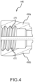
- FIGs. 1A-1B illustrate a non-limiting embodiment of a multi-piece fastener 100 according to the present disclosure.
- the multi-piece fastener 100 can be adapted to be installed in a bore in a structure (e.g., as illustrated in FIGs. 5A-5D and discussed below).
- the multi-piece fastener 100 can comprise at least two components, such as, for example, a fastening collar 102 and a pin 120 as illustrated in FIGs. 1A-1B , or in some non-limiting embodiments, at least three components (not shown).
- the multi-piece fastener 100 can comprise a two-piece assembly, including the fastening collar 102 and the pin 120.
- the multi-piece fastener 100 can comprise a lockbolt.
- the lockbolt can be a structural lockbolt fastener, such as, for example, a structural rivet, a structural bolt, or a structural stud.
- the fastening collar 102 can comprise a first collar end 104, a second collar end 106, an elongate portion 108 disposed intermediate the first collar end 104 and the second collar end 106, and a collar cavity 110 extending through the elongate portion 108 from the first collar end 104 to the second collar end 106.
- the elongate portion 108 can define a longitudinal axis of the fastening collar 102 and/or the multi-piece fastener 100.
- An inner surface 112 of the elongate portion 108 defining the collar cavity 110 can comprise at least one of a substantially cylindrical region, a threaded region, an annular shoulder, a groove, and other feature depending on the desired application.
- the fastening collar 102 can be sized and configured to engage with a fastening collar installation tool. Responsive to the engagement, the fastening collar 102 can be deformed onto a shank 122 of a pin 120 of the multi-piece fastener 100 to achieve a desired clamping force between the fastening collar 102 and the pin 120.
- the pin 120 can comprise a first pin end 128, a second pin end 130, and the shank 122.
- the shank 122 can comprise a shape and size suitable to be received by the collar cavity 110 of the fastening collar 102, such as, for example, a generally cylindrical shape.
- the shank 122 can extend intermediate the first pin end 128 and the second pin end 130 and can be dimensioned so that it can be disposed at least partially through the collar cavity 110.
- the second pin end 130 can be disposed adjacent to the second collar end 106
- the first pin end 128 can be disposed adjacent to the first collar end 104.
- the first pin end 128 can comprise a head portion 132 configured to inhibit the pin 120 from traversing completely through a bore in a structure.
- a diameter of a bore in a structure can comprise a diameter less than a diameter of the head portion 132 so that the head portion 132 cannot pass through the bore.
- the collar cavity 110 can be configured to receive the pin 120.
- the collar cavity 110 can comprise a first diameter, ⁇ 1 , greater than a second diameter, ⁇ 2 , of the shank 122.
- the fastening collar 102 can comprise a flange 114 comprising a third diameter, ⁇ 3 , sized and configured in order to inhibit the flange 114 of the fastening collar 102 from traversing through a bore in a structure.
- the fastening collar 102 can be generally cylindrical.
- the second diameter, ⁇ 2 , of the shank 122 can be at least 1.52 mm (0.06 inches), such as, for example, at least 2.54 mm (0.1 inch), at least 12.7 mm (0.5 inches), or at least 25.4 mm (1 inch). In various non-limiting embodiments, the second diameter, ⁇ 2 , of the shank 122 can be no greater than 102 mm (4 inches), such as, for example, no greater than 25.4 mm (1 inch), no greater than 12.7 mm (0.5 inches), or no greater than 2.54 mm (0.1 inch).
- the second diameter, ⁇ 2 , of the shank 122 can be in a range of 1.52 mm to 102 mm (0.06 inches to 4 inches), such as, for example, 1.52 mm to 25.4 mm (0.06 inches to 1 inches), or 1.52 mm to 12.7 mm (0.06 inches to 0.5 inches).
- the second pin end 130 can comprise a pull region 124 configured to be engaged by a fastening collar installation apparatus (e.g., fastening collar installation apparatus 240, as illustrated in FIGs. 2A-2B and discussed below).
- the pull region 124 can comprise an axial length, l , sized to be engaged by an installation tool.
- the axial length, l can be at least 0.5 times the second diameter, ⁇ 2 , of the shank 122, such as, for example, at least 1 times the second diameter, ⁇ 2 , of the shank 122, at least 2 times the second diameter, ⁇ 2 , of the shank 122, or at least 3 times the second diameter, ⁇ 2 , of the shank 122.
- the axial length, l can be no greater than 4 times the second diameter, ⁇ 2 , of the shank 122, such as, for example, no greater than 3 times the second diameter, ⁇ 2 , of the shank 122, no greater than 2 the second diameter, ⁇ 2 , of the shank 122, or no greater than 1 times the second diameter, ⁇ 2 , of the shank 122.
- the axial length, l can be in a range of 0.5 to 4 times the second diameter, ⁇ 2 , of the shank 122, such as for example, 0.5 times to 2 times the second diameter, ⁇ 2 , of the shank 122.
- the pull region 124 may not comprise a taper. In various other non-limiting embodiments, not in line with the claimed invention, the pull region 124 may comprise a taper or a reverse taper. For example, as one moves along the pull region 124 away from the shank 122 along a longitudinal axis of the pin 120, the diameter of the pull region 124 can decrease. In certain other non-limiting embodiments, the pull region 124 can comprise a reverse taper in which, as one moves along the pull region 124 away from the shank 122 along the longitudinal axis of the pin 120, the diameter of the pull region 124 can increase.
- the pull region 124 is generally cylindrical and smooth.
- the pull region 124 can be free of an annular shoulder, grooves, threads, or other features prior to forcible contact with a fastening collar installation apparatus.
- the annular shoulder, groove, thread, or other feature can form on the pull region 124 responsive to forcible contact with a fastening collar installation apparatus.
- the formation of the annular shoulder, groove, thread, and/or other feature on the pull region 124 can be responsive to installation of the multi-piece fastener 100 into a structure and, thus, provides a visual indication that the multi-piece fastener 100 has been installed into the structure.
- the shank 122 can define the longitudinal axis of the pin 120 and/or the multi-piece fastener 100.
- the shank 122 can be configured to engage the fastening collar 102 on installation in order to secure the shank 122 to the fastening collar 102.
- the longitudinal axis of the pin 120 and the longitudinal axis of the fastening collar 102 can be substantially aligned and form the longitudinal axis of the multi-piece fastener 100.
- the shank 122 of the pin 120 can comprise at least one of a generally smooth region, a threaded region, an annular shoulder, a groove, and other feature that is adapted to engage the surface 112 of the fastening collar 102 on installation.
- the threaded region, annular shoulder, groove, and/or other feature can be external relative to the shank 122.
- all or a portion of the shank 122 includes grooves.
- the shank 122 of the pin 120 includes grooves 126. In other non-limiting embodiments, all or a portion of the shank 122 lacks grooves.
- a portion of the shank 122 includes an annular shoulder. In other non-limiting embodiments, the shank 122 lacks an annular shoulder. In various non-limiting embodiments, a portion of the shank 122 includes a threaded portion. In other non-limiting embodiments, the shank 122 lacks a threaded portion.
- the collar cavity 110 of the fastening collar 102 can be configured to at least partially receive the shank 122 of the pin 120 therein.
- the collar cavity 110 can comprise a shape suitable to receive the shank 122 of the pin 120, such as, for example, a generally cylindrical shape.
- the fastening collar 102 can be at least partially deformed (e.g., swaged) onto the shank 122 responsive to forcible contact between the fastening collar 110 and a fastening collar installation apparatus, as described below. The deformation can secure the fastening collar 102 to the shank 122.
- the pin 120 may not comprise a breakneck groove or other feature configured to fracture upon installation of the multi-piece fastener 100, and the pull region 124 may stay intact after installation.
- the pin 120 may comprise a breakneck groove (not shown) or other feature configured to fracture upon installation of the multi-piece fastener 100.
- the pin 120 may not comprise a breakneck groove and may still be configured to fracture upon installation of the multi-piece fastener 100.
- the multi-piece fastener 100 may be installed into a structure without fracturing of a breakneck groove or other feature, or a breakneck groove or other feature may be provided and may be fractured upon installation of the multi-piece fastener into the structure.
- the multi-piece fastener system can comprise at least one of a metal, a metal alloy, a composite material, and another suitable material.
- the multi-piece fastener 100 can comprise at least one of aluminum, an aluminum alloy, titanium, a titanium alloy, nickel, a nickel alloy, iron, an iron alloy, and a carbon fiber composite material.
- the multi-piece fastener 100 comprises steel, such as, for example, stainless steel.
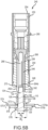
- FIGs. 2A-B illustrate a non-limiting embodiment of fastening collar installation apparatus 240 according to the present disclosure.
- the fastening collar installation apparatus 240 can engage at least a portion of a fastener system (e.g., the pull region 124 of the pin 120 of the fastener system illustrated in FIGs. 1A-B ) and/or deform a portion of the fastener system (e.g., deform the fastening collar 102 and/or break the pin 120 of the multi-piece fastener system 100 illustrated in FIGs. 1A-B ).
- the fastening collar installation apparatus 240 can be configured with various components in order to engage a pin of the multi-piece fastener, deform the fastening collar onto the pin, and/or break the pin.
- the fastening collar installation apparatus 240 can comprise an anvil 242, a housing 244, and a collet 246.
- the housing 244 can be configured to receive and/or retain various components.
- the housing 244 can comprise a housing cavity 268 extending along a longitudinal axis of the housing 244 from a first housing end 248 to the second housing end 250.
- the housing 244 can be substantially cylindrical.
- the housing cavity 268 can be configured to at least partially receive the collet 246.
- the anvil 242 can be configured to engage and/or deform a fastening collar of a multi-piece fastener system (e.g., fastening collar 102 in FIGs. 1A-1B ).
- the anvil 242 can be operatively coupled to the housing 244 and positioned adjacent to the first housing end 248.
- the anvil 242 is in direct contact with the first housing end 248.
- the anvil 242 can comprise an anvil cavity 270 extending along a longitudinal axis of the anvil 242.
- the anvil cavity 270 can be configured to receive at least a portion of the multi-piece fastener 100, such as, for example, at least a portion of the fastening collar 102 and/or the pin 120.
- the anvil 242 can have a toroidal shape.
- the collet 246 can be sized and configured such that the collet 246 can engage and/or move at least a portion of a fastener system (e.g., the pull region 124 of the pin 120 of the multi-piece fastener 100).
- the collet 246 can be positioned within the housing cavity 268 of the housing 244 and configured to move relative to the housing 244 and/or anvil 242 in order to draw a multi-piece fastener 100 engaged with the collet 246 into contact with the anvil 242, as described below with reference to FIGs. 5A-5D .
- the collet 246 can comprise a first collet end 252 adjacent to the anvil 242, a second collet end 254, a collet cavity 266 extending from the first collet end 252, and an elongate portion 258.
- the elongate portion 258 can comprise at least two fingers formed by at least two axial channels formed in the elongate portion 258.
- the elongate portion 258 can comprise three fingers 262a-c formed by three axial channels 264a-c as illustrated in FIG. 2A .
- the axial channels 264a-c can be substantially parallel to a longitudinal axis of the collet 246.
- the fingers 262a-c can be radially spaced about the longitudinal axis of the collet 246, and in various non-limiting embodiments, the fingers 262a-c can be substantially equally radially spaced about the longitudinal axis of the collet 246. Equally radially spacing the fingers 262a-c about the longitudinal axis of the collet 246 can facilitate centering of a fastening collar within the collet cavity 266 when the fastening collar installation apparatus 240 is in use.
- the first collet end 252 can comprise jaws to engage at least a portion of a fastener (e.g., the pull region 124).
- each finger 262a-c can comprise a respective jaw 256a-c extending inwardly relative to the longitudinal axis of the collet 246 and the collet cavity 266.
- the jaws 256a-c can comprise an annular shoulder (not shown), a groove, a thread, and/or other feature (not shown).
- a collet 346 is provided that comprises jaws 356a-b with grooves 378. As shown in the non-limiting embodiment illustrated in FIG.
- a collet 446 is provided comprising jaws 456a-b including threads 478.
- the jaws 256a-c, 356a-b, and 456a-b can comprise a 30-degree/60-degree chuck draw.
- the jaws 256a-c are configured to forcibly contact at least a portion of a pull region 124 of the pin 120 of a multi-piece fastener 100 and to form, for example, an annular shoulder, a groove, a thread, and/or other feature on the pull region 124.
- the jaws 256a-c can cold form an annular shoulder, a groove, a thread, and/or other feature onto the pull region 124 of the pin 120.
- the process of forming an annular shoulder, a groove, a thread, and/or other feature on the pull region 124 can increase the tensile strength and/or shear strength of the pin 120, which can increase the reliability of the multi-piece fastener 100 after installation. Additionally, forming the annular shoulder, groove, thread, and/or other feature on a generally cylindrical and smooth pull region 124 can increase the engagement between the collet 246 and the pin 120 compared to engagement between a collet and a pin pull region including a preformed annular shoulder, groove, thread, and/or other feature.
- the fastening collar installation apparatus 240 may form a single annular shoulder, groove, thread, or other feature on the pull region 124 of the pin 120. In certain non-limiting embodiments, the fastening collar installation apparatus 240 may form at least two annular shoulders, grooves, threads and/or other features on the pull region 124 of the pin 120.
- the collet 246 can be a single, continuous piece or can comprise multiple pieces.
- the fingers 262a-c can be joined together by bonding or other techniques or can be formed from a single piece of material.
- the fingers 262a-c can be independently moveable relative to one another and are not joined together.
- the collet 246 can be independently moveable relative to the housing 244 and/or anvil 242.
- the collet 246, including the jaws 256a-c can be configured to retract within the housing 244 and move the pull region 124 distal from the fastening collar 102 of the multi-piece fastener 100.
- the movement of the collet 246 can be responsive to a linear force acting on the collet.
- the second collet end 254 can be configured to engage a tool that can generate a linear force, such as, for example, a piston of a powered installation tool.
- the powered installation tool can be a battery-powered tool, such as, for example, at least one of a Huck ® Range Force TM battery-powered installation tool; a pneumatic tool, such as, for example, a Huck ® 254 pneumatic tool; and a hydraulic tool, such as, for example, a Huck ® SF hydraulic tool, all available from Arconic Fasteners, Waco, Texas.
- the collet 246 can be engaged with an adapter 260 that can engage a tool that can generate a linear force.
- the fastening collar installation apparatus 240 can comprise at least one of a metal, a metal alloy, a composite material, and another suitable material.
- the fastening collar installation apparatus 240 can comprise at least one of aluminum, an aluminum alloy, titanium, a titanium alloy, nickel, a nickel alloy, iron, an iron alloy, and a carbon fiber composite material.
- the collet 246 can comprise a first material with a first hardness
- the pin 120 can comprises a second material with a second hardness.
- the first hardness can be greater than the second hardness such that the collet 246 can deform the pull region 124 of first pin end 128 of the pin 120.
- the jaws 256a-c can apply a force to a surface of the pull region 124 that is greater than a yield strength of the second material in order to form an annular shoulder, a groove, a thread, and /or other feature on the pull region 124.
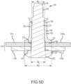
- the multi-piece fastener 100 can be installed into a bore 572 of a structure 570.
- the bore 572 can extend through the structure 570 from a first side 574 to a second side 576.
- the structure 570 can comprise, for example, at least one of a metal, a metal alloy, a composite material, or another suitable material.
- the structure 570 can comprise at least one of aluminum, an aluminum alloy, titanium, a titanium alloy, nickel, a nickel alloy, iron, an iron alloy, and a carbon fiber composite material.
- the structure 570 into which the multi-piece fastener 100 is assembled comprises aluminum and/or an aluminum alloy, such as, for example, 7075 aluminum alloy.
- the structure 570 can be configured as at least one of an aerospace component or structure, an automotive component or structure, a transportation component or structure, a building and construction component or structure, or another component or structure.
- the structure 570 can comprise a single layer of material or at least two layers of material.
- the structure 570 can comprise a first layer 570a and a second layer 570b.
- the first layer 570a can be intermediate the second layer 570b and the fastening collar 102 when the fastening collar 102 is installed.
- the first layer 570a is adjacent to the fastening collar 102.
- the bore 572 can have a bore diameter, ⁇ b .
- the second diameter, ⁇ 2 , of the shank 122 can be sized and configured to be less than the bore diameter, ⁇ b , thereby allowing the second pin end 130 to be readily disposed into and through the bore 572.
- the bore diameter, ⁇ b can be less than a diameter of the head portion 132 in order to inhibit the head portion 132 of the pin 120 from moving into the bore 572.
- the second pin end 130 of the pin 120 was positioned in alignment with the bore 572 on the second side 576 of the structure 570 before being inserted through the bore 572.
- the fastening collar 102 has been positioned over the second pin end 130, and the second pin end 130 has been inserted into and through the collar cavity 110 of the fastening collar 102.
- the first collar end 104 of the fastening collar 102 has been positioned to contact the first layer 570a of the structure 570.
- the fastening collar 102 can be in forcible contact with the structure 570, which can limit further axial movement of the fastening collar 102 relative to the pin 120 along the longitudinal axis of the multi-piece fastener 100.
- inserting the second pin end 130 into the collar cavity 110 of the fastening collar 102 may require rotation of at least one of the fastening collar 102 and the pin 120.
- the collet 246 of the fastening collar installation apparatus 240 has engaged the shank 122 of the pin 120 of the multi-piece fastener 100.
- the collet 246 was positioned over the pull region 124 of the multi-piece fastener 100 and retracted within the housing 244 of the fastening collar installation apparatus 240, which has caused the collet 246 to forcibly contact the anvil 242 of the fastening collar installation apparatus 240.
- the jaws 256a-c have closed around the pull region 124 and have forcibly contacted the pull region 124 of pin 120.
- the forcible contact between the jaws 256a-c and the pull region 124 has mechanically deformed the pull region 124 to form an annular shoulder, a groove, a thread, and/or other feature on the pull region 124, thereby engaging the collet 246 with the pin 120.
- the collet 246 can apply an axial force to the pull region 124 of the pin 120, which can decrease a gap, if present, between the first layer 570a and the second layer 570b of the structure 570 and create forcible contact between the fastening collar 102 and the structure 570.
- the collet 246 has further retracted within the fastening collar installation apparatus 240 and moved the pin 120 due to the engagement between the pull region 124 and the collet 246.
- the anvil 242 can contact the fastening collar 102.
- the fastening collar 102 can be at least partially deformed responsive to the forcible contact between the anvil 242 and the fastening collar 102.
- the fastening collar 102 can be swaged onto a generally smooth region, a threaded region, an annular shoulder, a groove, and/or other feature on a section of the shank 122 intermediate the first layer 570a and the second pin end 130.
- At least partially deforming the fastening collar 102 onto the shank 122 of the pin 120 can thereby secure the fastening collar 102 to the shank 122 and secure the multi-piece fastener 100 to at least a portion of the structure 570.
- the first layer 570a and second layer 570b of the structure 570 are secured together (e.g., inhibited from axial movement along the longitudinal axis of the multi-piece fastener 100).
- the fastening collar 102 and the head portion 132 of the pin 120 are applying a clamping force to the layers 570a-b of the structure 570, thereby securing the multi-piece fastener 100 to the structure 570 and securing layers 570a-b together.
- an annular shoulder, a groove, a thread, and/or other feature has been formed on the pull region 124 of the pin 120 by the collet 246 of the fastening collar installation apparatus 240, thus providing a visual indication that the multi-piece fastener 100 has been installed.
- the pin 120 may not fracture after installation into the structure 570.
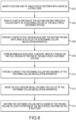
- the present disclosure includes methods for installing a fastener and fastening a structure, as described and illustrated herein.
- the multi-piece fastener systems according to the present disclosure can be used in a method for fastening a structure.
- a second end of a multi-piece fastener according to the present disclosure can be inserted into a bore in a structure, 602.
- At least a portion of the second pin end can be passed through a collar cavity of a fastening collar of the multi-piece fastener according to the present disclosure, 604.
- the pull region of the pin can be forcibly contacted with jaws of a collet of a fastening collar installation apparatus according to the present disclosure, 606.
- An annular shoulder, a groove, a thread, and/or other feature can be formed on the pull region of the pin of the multi-piece fastener system according to the present disclosure by the jaws of the collet of the fastening collar installation apparatus according to the present disclosure, 608.
- the jaws of the collet of the fastening collar installation apparatus according to the present disclosure can apply a force to a surface of the pull region that is greater than a yield strength of the pull region.
- the fastening collar can be forcibly contacted with an anvil of the fastening collar installation apparatus, 610.
- the pull region can be moved distal from the fastening collar utilizing the collet of the fastening collar installation apparatus according to the present disclosure, 612.
- the fastening collar installation apparatus deforms the fastening collar onto the shank of the pin and secures at least a portion of the multi-piece fastener according to the present disclosure in the structure, 614.
Landscapes
- Engineering & Computer Science (AREA)
- General Engineering & Computer Science (AREA)
- Mechanical Engineering (AREA)
- Insertion Pins And Rivets (AREA)
Claims (15)
- Élément de fixation en plusieurs pièces (100) comprenant :un collier de fixation (102) comprenant :une première extrémité de collier (104) ; etune seconde extrémité de collier (106),dans lequel une cavité de collier (110) s'étend de la première extrémité de collier à la seconde extrémité de collier ; etune broche (120) configurée pour être au moins partiellement reçue par la cavité du collier, la broche comprenantune première extrémité de broche (128) comprenant une partie de tête (132) ;une seconde extrémité de broche (130) comprenant une région de traction (124), dans laquelle la région de traction est généralement cylindrique et lisse et est configurée pour former au moins un parmi un épaulement annulaire, une rainure, un filetage, et une autre caractéristique sur celle-ci en réponse à un contact forcé provenant d'un appareil d'installation de collier de fixation (240) ; etune tige (122) s'étendant entre la première extrémité de broche et la seconde extrémité de broche, dans laquelle le collier de fixation est configuré pour être déformé sur la tige.
- Élément de fixation en plusieurs pièces (100) selon la revendication 1, dans lequel la région de traction (124) comprend une longueur axiale (1) non supérieure à 4 fois un diamètre (ø2) de la tige (122), et/ou dans lequel un diamètre (ø2) de la tige est dans une plage de 1,52 mm à 102 mm (0,06 pouce à 4 pouces), de préférence de 1,52 mm à 25,4 mm (0,06 pouce à 1 pouce), plus préférablement de 1,52 mm à 12,7 pouces (0,06 pouce à 0,5 pouce).
- Élément de fixation en plusieurs pièces (100) selon la revendication 1 ou la revendication 2, dans lequel la tige (122) comprend au moins un parmi un épaulement annulaire, une rainure, une région filetée et une autre caractéristique, et/ou dans lequel la région de traction (124) est exempte d'épaulement annulaire, de rainures, de filetages et d'autres caractéristiques avant le contact forcé d'un appareil d'installation de collier de fixation (240).
- Élément de fixation en plusieurs pièces (100) selon l'une quelconque des revendications 1 à 3, dans lequel le collier de fixation (102) est généralement cylindrique, et/ou dans lequel le collier de fixation comprend une bride (114).
- Élément de fixation en plusieurs pièces (100) selon l'une quelconque des revendications 1 à 4, dans lequel l'élément de fixation en plusieurs pièces est adapté pour être installé dans un alésage (572) dans une structure (570), l'alésage ayant un diamètre (øb) inférieur à un diamètre de la partie de tête (132), de préférence dans lequel la structure est configurée comme au moins un d'une partie ou d'un composant aérospatial, d'une partie ou d'un composant automobile, d'une partie ou d'un composant de transport, et d'une partie ou d'un composant de bâtiment et de construction
- Élément de fixation en plusieurs pièces (100) selon l'une quelconque des revendications 1 à 5, dans lequel l'élément de fixation en plusieurs pièces comprend au moins un parmi un métal, un alliage métallique et un composite.
- Boulon de verrouillage comprenant l'élément de fixation en plusieurs pièces (100) selon l'une quelconque des revendications 1 à 6.
- Appareil d'installation de collier de fixation (240) comprenant :un logement (244) comprenantune première extrémité de logement (248) ; etune seconde extrémité de logement (250),dans lequel une cavité de logement (268) s'étend de la première extrémité de logement à la seconde extrémité de logement ;un étrier (242) positionné à l'intérieur de la cavité de logement ; etune pince de serrage (246) positionnée à l'intérieur de la cavité de logement, la pince de serrage comprenant une première extrémité de pince de serrage (252) adjacente à l'étrier, caractérisée en ce que la première extrémité de pince de serrage comprend des mâchoires (256a-c, 356a-c, 456a-c) configurées pour venir en contact forcé avec au moins une partie d'une région de traction (124) d'un élément de fixation en plusieurs pièces (100) et pour former au moins un parmi un épaulement annulaire, une rainure, un filetage et une autre caractéristique sur la région de traction.
- Appareil d'installation de collier de fixation (240) selon la revendication 8, dans lequel les mâchoires (256a-c, 356a-c, 456a-c) de la pince de serrage (246) comprennent au moins un parmi un épaulement annulaire, une rainure, un filetage et une autre caractéristique.
- Appareil d'installation de collier de fixation (240) selon la revendication 8 ou la revendication 9, dans lequel la pince de serrage (246) est une pièce unique continue ou plusieurs pièces, et/ou
dans lequel la pince de serrage comprend :une seconde extrémité de pince de serrage (254) ; etune partie allongée (258) s'étendant de la première extrémité de pince de serrage (252) à la seconde extrémité de pince de serrage, la partie allongée comprenant au moins deux doigts (262a-c) formés par au moins deux canaux axiaux (264a-c) dans la partie allongée. - Appareil d'installation de collier de fixation (240) selon l'une quelconque des revendications 8 à 10, dans lequel l'élément de fixation en plusieurs pièces (100) comprend :un collier de fixation (102) comprenantune première extrémité de collier (104) ; etune seconde extrémité de collier (106),dans lequel une cavité de collier (110) s'étend de la première extrémité de collier à la seconde extrémité de collier ; etune broche (120) configurée pour être au moins partiellement reçue par la cavité du collier, la broche comprenantune première extrémité de broche (128) comprenant une partie de tête (132) ;une seconde extrémité de broche (130) comprenant la région de traction (124), dans laquelle la région de traction est généralement cylindrique et lisse et est configurée pour former au moins un parmi un épaulement annulaire, une rainure, un filetage et une autre caractéristique sur celle-ci en réponse à un contact forcé de l'appareil d'installation de collier de fixation ; etune tige (122) s'étendant entre la première extrémité de broche et la seconde extrémité de broche, dans laquelle le collier de fixation est configuré pour être déformé sur la tige.
- Procédé de fixation, le procédé comprenant :l'insertion d'une seconde extrémité de broche (130) d'un élément de fixation en plusieurs pièces (100) dans un alésage (572) dans une structure (570), l'élément de fixation en plusieurs pièces comprenantun collier de fixation (102) comprenantune première extrémité de collier (104) ; etune seconde extrémité de collier (106),dans lequel une cavité de collier (110) s'étend de la première extrémité de collier à la seconde extrémité de collier, etune broche (120) configurée pour être au moins partiellement reçue par la cavité du collier, la broche comprenantune première extrémité de broche (128) comprenant une partie de tête (132) ;la seconde extrémité de broche comprenant une région de traction (124), dans laquelle la région de traction est généralement cylindrique et lisse ; etune tige (122) s'étendant entre la première extrémité de broche et la seconde extrémité de broche ;le passage d'au moins une partie de la seconde extrémité de broche à travers la cavité de collier ;le contact forcé de la région de traction de la broche avec des mâchoires (256a-c, 356a-c, 456a-c) d'une pince de serrage (246) d'un appareil d'installation de collier de fixation (240) et la formation d'au moins un parmi un épaulement annulaire, une rainure, un filetage et une autre caractéristique sur la région de traction ; etle contact forcé du collier de fixation avec un étrier (242) de l'appareil d'installation de collier de fixation et le déplacement de la région de traction distale par rapport au collier de fixation à l'aide de la pince de serrage de l'appareil d'installation de collier de fixation, déformant ainsi le collier de fixation sur la tige de la broche et fixant au moins une partie de l'élément de fixation en plusieurs pièces dans la structure.
- Procédé selon la revendication 12, dans lequel l'appareil d'installation de collier de fixation (240) comprend :un logement (244) comprenantune première extrémité de logement (248) ; etune seconde extrémité de logement (250),dans lequel une cavité de logement (268) s'étend de la première extrémité de logement jusqu'à la seconde extrémité de logement,dans lequel l'étrier (242) et la pince de serrage (246) sont positionnés à l'intérieur de la cavité de logement,dans lequel la pince de serrage comprend une première extrémité de pince de serrage (252) adjacente à l'étrier, la première extrémité de pince de serrage comprend les mâchoires (256a-c, 356a-c, 456a-c), et la pince de serrage est une pièce unique continue.
- Procédé selon la revendication 12 ou la revendication 13, dans lequel la pince de serrage (246) comprend un premier matériau ayant une première dureté, la broche (120) comprend un second matériau ayant une seconde dureté, et la première dureté est supérieure à la seconde dureté.
- Procédé selon l'une quelconque des revendications 12 à 14, dans lequel la mise en contact forcée de la région de traction (124) de la broche (120) avec des mâchoires (256a-c, 356a-c, 456a-c) de la pince de serrage (246) de l'appareil d'installation de collier de fixation (240) et la formation d'au moins un parmi un épaulement annulaire, une rainure, un filetage et une autre caractéristique sur la région de traction comprend l'application d'une force avec les mâchoires sur une surface de la région de traction qui est supérieure à une force de déformation de la région de traction.
Applications Claiming Priority (1)
| Application Number | Priority Date | Filing Date | Title |
|---|---|---|---|
| PCT/US2019/060082 WO2021091553A1 (fr) | 2019-11-06 | 2019-11-06 | Attaches en plusieurs pièces, appareil d'installation de collier de fixation et procédés de fixation |
Publications (4)
| Publication Number | Publication Date |
|---|---|
| EP4055285A1 EP4055285A1 (fr) | 2022-09-14 |
| EP4055285A4 EP4055285A4 (fr) | 2023-07-19 |
| EP4055285C0 EP4055285C0 (fr) | 2024-09-18 |
| EP4055285B1 true EP4055285B1 (fr) | 2024-09-18 |
Family
ID=75848867
Family Applications (1)
| Application Number | Title | Priority Date | Filing Date |
|---|---|---|---|
| EP19951503.2A Active EP4055285B1 (fr) | 2019-11-06 | 2019-11-06 | Attaches en plusieurs pièces, appareil d'installation de collier de fixation et procédés de fixation |
Country Status (5)
| Country | Link |
|---|---|
| US (2) | US20220397145A1 (fr) |
| EP (1) | EP4055285B1 (fr) |
| AU (2) | AU2019473410B2 (fr) |
| ES (1) | ES2991672T3 (fr) |
| WO (1) | WO2021091553A1 (fr) |
Families Citing this family (7)
| Publication number | Priority date | Publication date | Assignee | Title |
|---|---|---|---|---|
| CN110762100A (zh) * | 2019-11-28 | 2020-02-07 | 眉山中车紧固件科技有限公司 | 一种用于导电材料紧固连接的拉铆钉 |
| USD1121426S1 (en) * | 2020-12-17 | 2026-04-07 | Sps Technologies, Llc | Blind fastener |
| WO2023102348A1 (fr) * | 2021-11-30 | 2023-06-08 | Howmet Aerospace Inc. | Éléments de fixation multi-pièces et procédés de fixation associés |
| EP4572902A1 (fr) * | 2022-08-17 | 2025-06-25 | Howmet Aerospace Inc. | Système et outil pour installer des éléments de fixation avancés sur un boulon en u |
| EP4435277B1 (fr) * | 2023-03-23 | 2025-11-26 | Avdel UK Limited | Élément de fixation, ensemble de fixation et procédé d'installation d'un élément de fixation |
| USD1119494S1 (en) * | 2024-03-15 | 2026-03-24 | Yuexiang Wang | Riveting tool |
| USD1101547S1 (en) * | 2024-11-08 | 2025-11-11 | Jianrong Liang | Wire installing tool |
Family Cites Families (7)
| Publication number | Priority date | Publication date | Assignee | Title |
|---|---|---|---|---|
| US3122948A (en) * | 1964-03-03 | iwentorv | ||
| US4347728A (en) * | 1979-05-30 | 1982-09-07 | Huck Manufacturing Company | Apparatus and system for setting fasteners |
| JPH0819925B2 (ja) * | 1985-04-29 | 1996-03-04 | ハック、インターナショナル、インコーポレーテッド | 可変締め付け応力ファスナー |
| US5049016A (en) * | 1989-06-07 | 1991-09-17 | Huck Manufacturing Company | Swage fasteners with a high stand-off collar |
| US5620287A (en) * | 1995-12-01 | 1997-04-15 | Textron Inc. | Fastener system with controlled clamping load |
| JP5393620B2 (ja) * | 2010-08-27 | 2014-01-22 | ハック インターナショナル,インコーポレイテッド | 締結具 |
| WO2015168063A1 (fr) * | 2014-04-29 | 2015-11-05 | Alcoa Inc. | Éléments de fixation de verrouillage emboutis |
-
2019
- 2019-11-06 AU AU2019473410A patent/AU2019473410B2/en active Active
- 2019-11-06 ES ES19951503T patent/ES2991672T3/es active Active
- 2019-11-06 EP EP19951503.2A patent/EP4055285B1/fr active Active
- 2019-11-06 WO PCT/US2019/060082 patent/WO2021091553A1/fr not_active Ceased
- 2019-11-06 US US17/754,026 patent/US20220397145A1/en not_active Abandoned
-
2024
- 2024-02-09 AU AU2024200862A patent/AU2024200862A1/en active Pending
-
2025
- 2025-03-26 US US19/091,404 patent/US20250223991A1/en active Pending
Also Published As
| Publication number | Publication date |
|---|---|
| EP4055285A4 (fr) | 2023-07-19 |
| US20220397145A1 (en) | 2022-12-15 |
| EP4055285C0 (fr) | 2024-09-18 |
| ES2991672T3 (es) | 2024-12-04 |
| AU2019473410B2 (en) | 2024-02-29 |
| AU2019473410A1 (en) | 2022-04-14 |
| WO2021091553A1 (fr) | 2021-05-14 |
| US20250223991A1 (en) | 2025-07-10 |
| EP4055285A1 (fr) | 2022-09-14 |
| AU2024200862A1 (en) | 2024-02-29 |
Similar Documents
| Publication | Publication Date | Title |
|---|---|---|
| EP4055285B1 (fr) | Attaches en plusieurs pièces, appareil d'installation de collier de fixation et procédés de fixation | |
| US5810530A (en) | Interference blind type bolt | |
| US6213699B1 (en) | Filling rivet with high pin lock | |
| US20240133409A1 (en) | Blind fastener and method of installation thereof | |
| AU2021264070B2 (en) | Multi-piece fastener including a lockbolt collar assembly and method of fastening | |
| US20250084884A1 (en) | Fastening collars, multi-piece fasteners, and methods for fastening | |
| AU2024278347A1 (en) | Multi-piece fastener comprising a tapered threaded portion and method of fastening | |
| EP4132749B1 (fr) | Systèmes de fixation, appareil d'installation de système de fixation, et procédés de fixation | |
| US11841041B1 (en) | Fastening collars, multi-piece fastening systems, and methods of fastening | |
| EP3969764B1 (fr) | Éléments de fixation en aveugle et procédés de fixation | |
| EP4259944B1 (fr) | Colliers de fixation, éléments de fixation en plusieurs parties, et procédés de fixation | |
| WO2026084726A1 (fr) | Éléments de fixation de boulon de verrouillage et procédés de fixation |
Legal Events
| Date | Code | Title | Description |
|---|---|---|---|
| STAA | Information on the status of an ep patent application or granted ep patent |
Free format text: STATUS: THE INTERNATIONAL PUBLICATION HAS BEEN MADE |
|
| PUAI | Public reference made under article 153(3) epc to a published international application that has entered the european phase |
Free format text: ORIGINAL CODE: 0009012 |
|
| STAA | Information on the status of an ep patent application or granted ep patent |
Free format text: STATUS: REQUEST FOR EXAMINATION WAS MADE |
|
| 17P | Request for examination filed |
Effective date: 20220324 |
|
| AK | Designated contracting states |
Kind code of ref document: A1 Designated state(s): AL AT BE BG CH CY CZ DE DK EE ES FI FR GB GR HR HU IE IS IT LI LT LU LV MC MK MT NL NO PL PT RO RS SE SI SK SM TR |
|
| DAV | Request for validation of the european patent (deleted) | ||
| DAX | Request for extension of the european patent (deleted) | ||
| REG | Reference to a national code |
Ref country code: DE Free format text: PREVIOUS MAIN CLASS: F16B0019050000 Ref country code: DE Ref legal event code: R079 Ref document number: 602019059317 Country of ref document: DE Free format text: PREVIOUS MAIN CLASS: F16B0019050000 Ipc: F16B0005040000 |
|
| A4 | Supplementary search report drawn up and despatched |
Effective date: 20230621 |
|
| RIC1 | Information provided on ipc code assigned before grant |
Ipc: F16B 19/05 20060101ALI20230615BHEP Ipc: F16B 5/04 20060101AFI20230615BHEP |
|
| GRAP | Despatch of communication of intention to grant a patent |
Free format text: ORIGINAL CODE: EPIDOSNIGR1 |
|
| STAA | Information on the status of an ep patent application or granted ep patent |
Free format text: STATUS: GRANT OF PATENT IS INTENDED |
|
| INTG | Intention to grant announced |
Effective date: 20240510 |
|
| GRAS | Grant fee paid |
Free format text: ORIGINAL CODE: EPIDOSNIGR3 |
|
| GRAA | (expected) grant |
Free format text: ORIGINAL CODE: 0009210 |
|
| STAA | Information on the status of an ep patent application or granted ep patent |
Free format text: STATUS: THE PATENT HAS BEEN GRANTED |
|
| AK | Designated contracting states |
Kind code of ref document: B1 Designated state(s): AL AT BE BG CH CY CZ DE DK EE ES FI FR GB GR HR HU IE IS IT LI LT LU LV MC MK MT NL NO PL PT RO RS SE SI SK SM TR |
|
| REG | Reference to a national code |
Ref country code: GB Ref legal event code: FG4D |
|
| REG | Reference to a national code |
Ref country code: CH Ref legal event code: EP |
|
| REG | Reference to a national code |
Ref country code: IE Ref legal event code: FG4D |
|
| REG | Reference to a national code |
Ref country code: DE Ref legal event code: R096 Ref document number: 602019059317 Country of ref document: DE |
|
| U01 | Request for unitary effect filed |
Effective date: 20241015 |
|
| REG | Reference to a national code |
Ref country code: ES Ref legal event code: FG2A Ref document number: 2991672 Country of ref document: ES Kind code of ref document: T3 Effective date: 20241204 |
|
| U07 | Unitary effect registered |
Designated state(s): AT BE BG DE DK EE FI FR IT LT LU LV MT NL PT RO SE SI Effective date: 20241030 |
|
| U20 | Renewal fee for the european patent with unitary effect paid |
Year of fee payment: 6 Effective date: 20241129 |
|
| PG25 | Lapsed in a contracting state [announced via postgrant information from national office to epo] |
Ref country code: NO Free format text: LAPSE BECAUSE OF FAILURE TO SUBMIT A TRANSLATION OF THE DESCRIPTION OR TO PAY THE FEE WITHIN THE PRESCRIBED TIME-LIMIT Effective date: 20241218 |
|
| PG25 | Lapsed in a contracting state [announced via postgrant information from national office to epo] |
Ref country code: GR Free format text: LAPSE BECAUSE OF FAILURE TO SUBMIT A TRANSLATION OF THE DESCRIPTION OR TO PAY THE FEE WITHIN THE PRESCRIBED TIME-LIMIT Effective date: 20241219 |
|
| PG25 | Lapsed in a contracting state [announced via postgrant information from national office to epo] |
Ref country code: HR Free format text: LAPSE BECAUSE OF FAILURE TO SUBMIT A TRANSLATION OF THE DESCRIPTION OR TO PAY THE FEE WITHIN THE PRESCRIBED TIME-LIMIT Effective date: 20240918 |
|
| PG25 | Lapsed in a contracting state [announced via postgrant information from national office to epo] |
Ref country code: RS Free format text: LAPSE BECAUSE OF FAILURE TO SUBMIT A TRANSLATION OF THE DESCRIPTION OR TO PAY THE FEE WITHIN THE PRESCRIBED TIME-LIMIT Effective date: 20241218 |
|
| PG25 | Lapsed in a contracting state [announced via postgrant information from national office to epo] |
Ref country code: RS Free format text: LAPSE BECAUSE OF FAILURE TO SUBMIT A TRANSLATION OF THE DESCRIPTION OR TO PAY THE FEE WITHIN THE PRESCRIBED TIME-LIMIT Effective date: 20241218 Ref country code: NO Free format text: LAPSE BECAUSE OF FAILURE TO SUBMIT A TRANSLATION OF THE DESCRIPTION OR TO PAY THE FEE WITHIN THE PRESCRIBED TIME-LIMIT Effective date: 20241218 Ref country code: HR Free format text: LAPSE BECAUSE OF FAILURE TO SUBMIT A TRANSLATION OF THE DESCRIPTION OR TO PAY THE FEE WITHIN THE PRESCRIBED TIME-LIMIT Effective date: 20240918 Ref country code: GR Free format text: LAPSE BECAUSE OF FAILURE TO SUBMIT A TRANSLATION OF THE DESCRIPTION OR TO PAY THE FEE WITHIN THE PRESCRIBED TIME-LIMIT Effective date: 20241219 |
|
| PG25 | Lapsed in a contracting state [announced via postgrant information from national office to epo] |
Ref country code: IS Free format text: LAPSE BECAUSE OF FAILURE TO SUBMIT A TRANSLATION OF THE DESCRIPTION OR TO PAY THE FEE WITHIN THE PRESCRIBED TIME-LIMIT Effective date: 20250118 |
|
| PG25 | Lapsed in a contracting state [announced via postgrant information from national office to epo] |
Ref country code: SM Free format text: LAPSE BECAUSE OF FAILURE TO SUBMIT A TRANSLATION OF THE DESCRIPTION OR TO PAY THE FEE WITHIN THE PRESCRIBED TIME-LIMIT Effective date: 20240918 |
|
| PG25 | Lapsed in a contracting state [announced via postgrant information from national office to epo] |
Ref country code: PL Free format text: LAPSE BECAUSE OF FAILURE TO SUBMIT A TRANSLATION OF THE DESCRIPTION OR TO PAY THE FEE WITHIN THE PRESCRIBED TIME-LIMIT Effective date: 20240918 Ref country code: CZ Free format text: LAPSE BECAUSE OF FAILURE TO SUBMIT A TRANSLATION OF THE DESCRIPTION OR TO PAY THE FEE WITHIN THE PRESCRIBED TIME-LIMIT Effective date: 20240918 |
|
| PG25 | Lapsed in a contracting state [announced via postgrant information from national office to epo] |
Ref country code: SK Free format text: LAPSE BECAUSE OF FAILURE TO SUBMIT A TRANSLATION OF THE DESCRIPTION OR TO PAY THE FEE WITHIN THE PRESCRIBED TIME-LIMIT Effective date: 20240918 |
|
| REG | Reference to a national code |
Ref country code: CH Ref legal event code: PL |
|
| PG25 | Lapsed in a contracting state [announced via postgrant information from national office to epo] |
Ref country code: MC Free format text: LAPSE BECAUSE OF FAILURE TO SUBMIT A TRANSLATION OF THE DESCRIPTION OR TO PAY THE FEE WITHIN THE PRESCRIBED TIME-LIMIT Effective date: 20240918 |
|
| REG | Reference to a national code |
Ref country code: CH Ref legal event code: PL |
|
| PG25 | Lapsed in a contracting state [announced via postgrant information from national office to epo] |
Ref country code: CH Free format text: LAPSE BECAUSE OF NON-PAYMENT OF DUE FEES Effective date: 20241130 |
|
| PLBE | No opposition filed within time limit |
Free format text: ORIGINAL CODE: 0009261 |
|
| STAA | Information on the status of an ep patent application or granted ep patent |
Free format text: STATUS: NO OPPOSITION FILED WITHIN TIME LIMIT |
|
| 26N | No opposition filed |
Effective date: 20250619 |
|
| PG25 | Lapsed in a contracting state [announced via postgrant information from national office to epo] |
Ref country code: IE Free format text: LAPSE BECAUSE OF NON-PAYMENT OF DUE FEES Effective date: 20241106 |
|
| U20 | Renewal fee for the european patent with unitary effect paid |
Year of fee payment: 7 Effective date: 20251022 |
|
| PGFP | Annual fee paid to national office [announced via postgrant information from national office to epo] |
Ref country code: GB Payment date: 20251023 Year of fee payment: 7 |
|
| PGFP | Annual fee paid to national office [announced via postgrant information from national office to epo] |
Ref country code: ES Payment date: 20251201 Year of fee payment: 7 |
|
| PG25 | Lapsed in a contracting state [announced via postgrant information from national office to epo] |
Ref country code: HU Free format text: LAPSE BECAUSE OF FAILURE TO SUBMIT A TRANSLATION OF THE DESCRIPTION OR TO PAY THE FEE WITHIN THE PRESCRIBED TIME-LIMIT; INVALID AB INITIO Effective date: 20191106 |
|
| PG25 | Lapsed in a contracting state [announced via postgrant information from national office to epo] |
Ref country code: CY Free format text: LAPSE BECAUSE OF FAILURE TO SUBMIT A TRANSLATION OF THE DESCRIPTION OR TO PAY THE FEE WITHIN THE PRESCRIBED TIME-LIMIT; INVALID AB INITIO Effective date: 20191106 |